


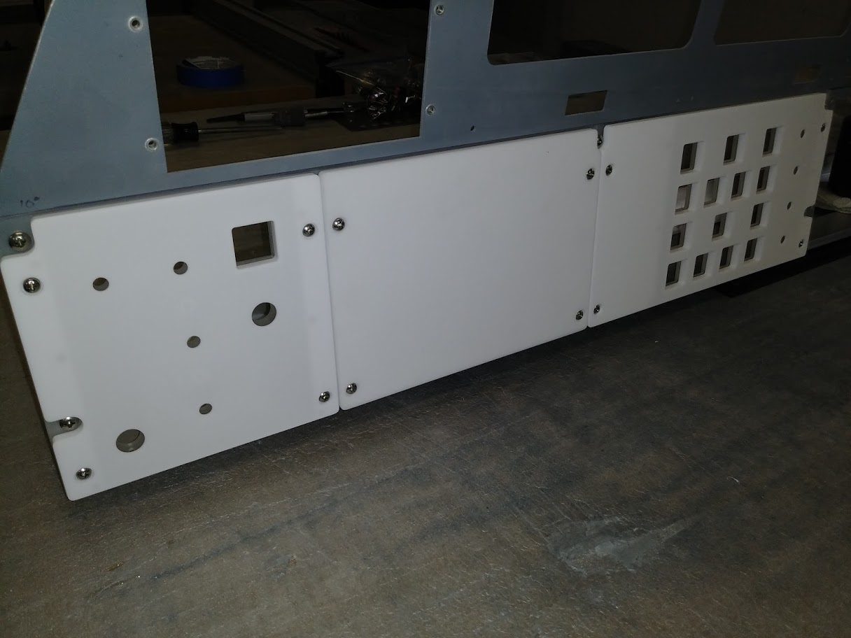
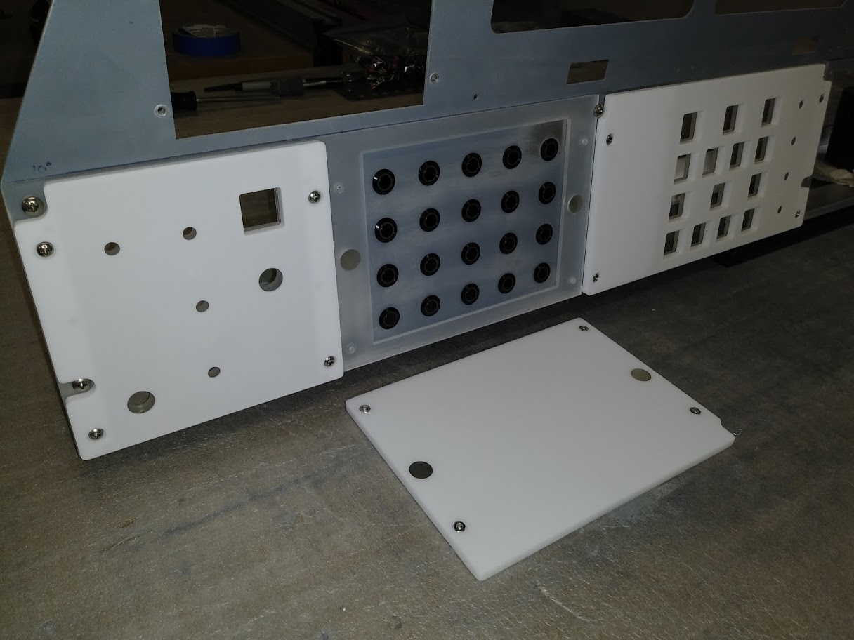
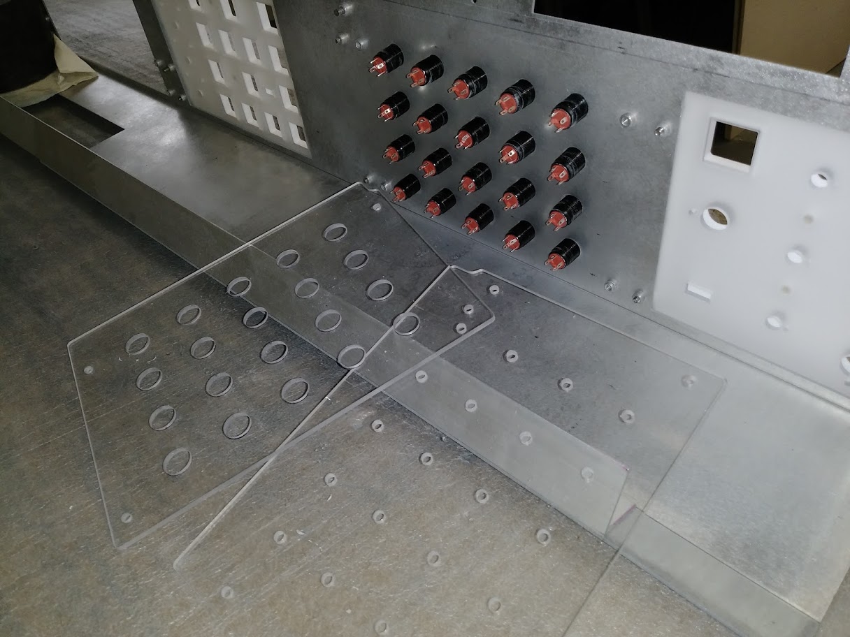
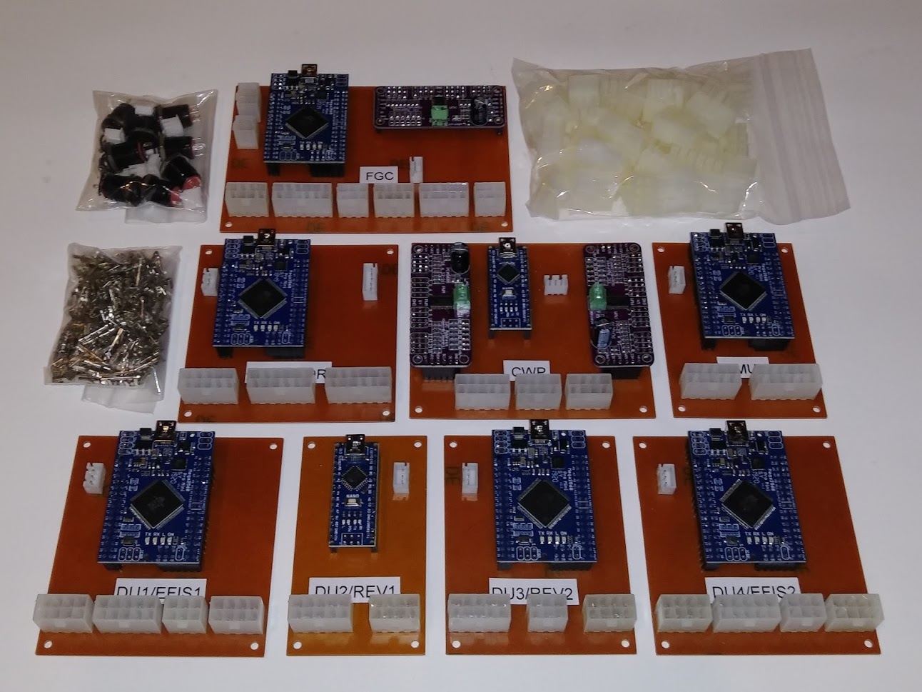
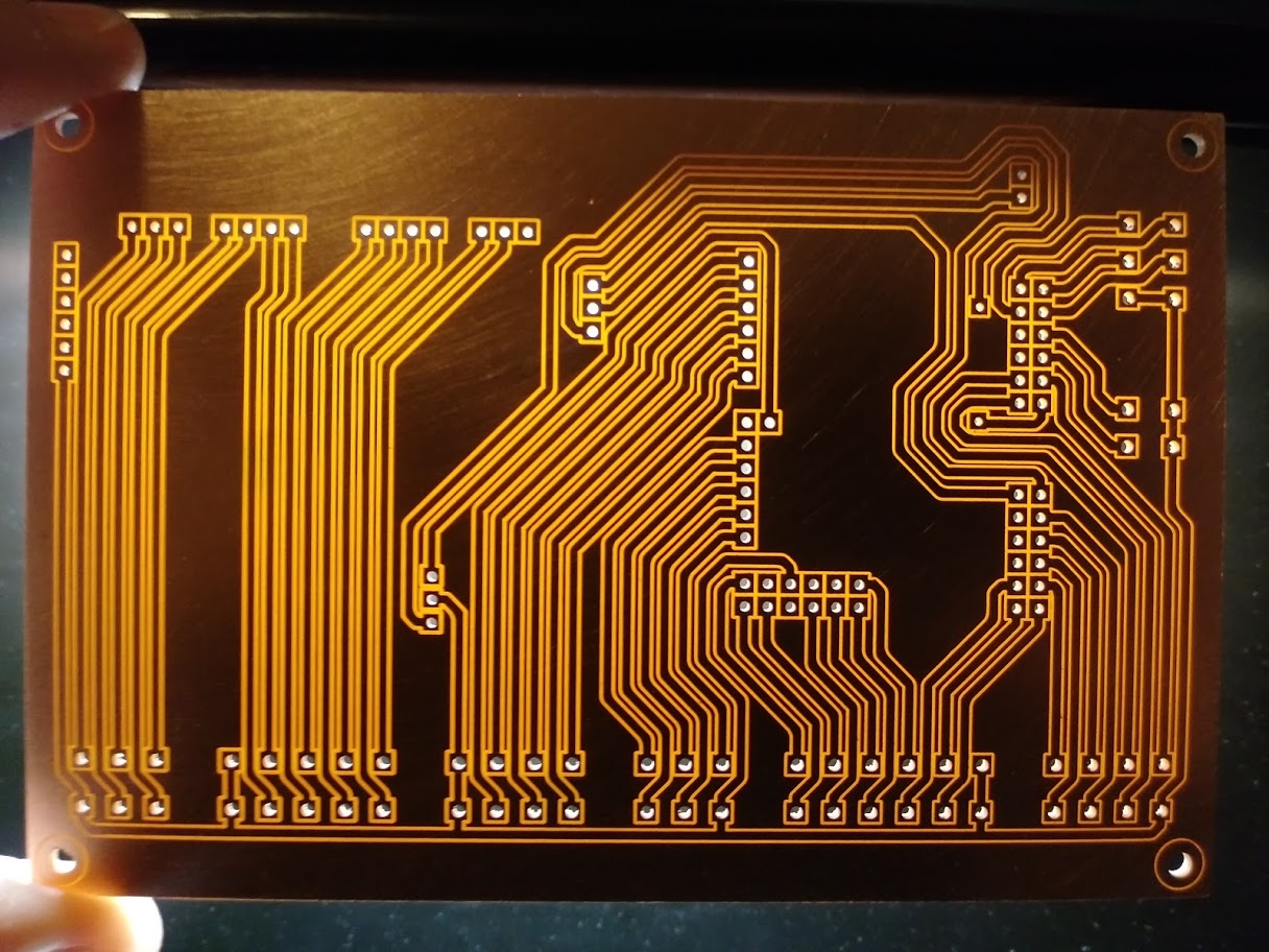
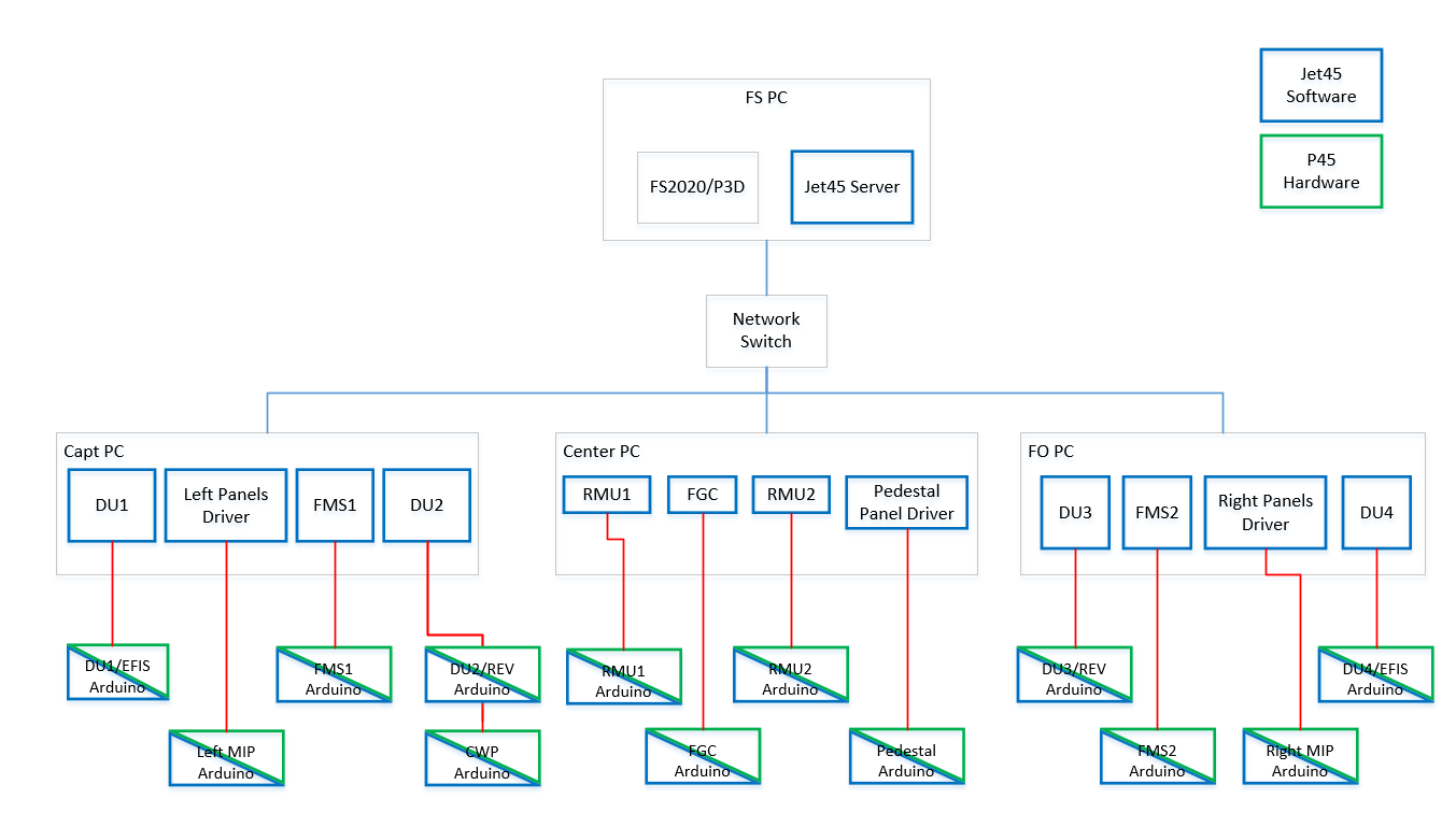
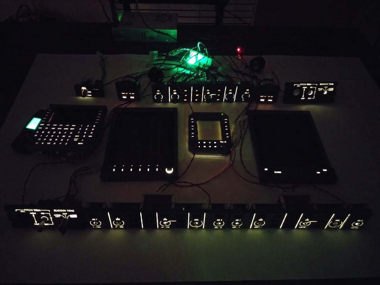
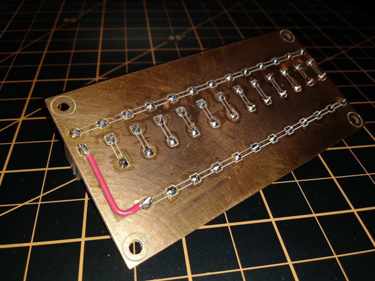
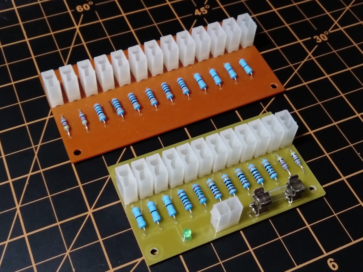
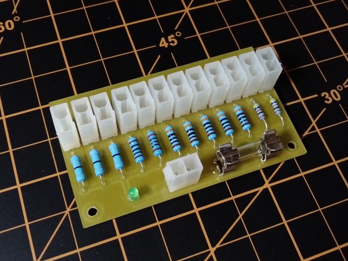
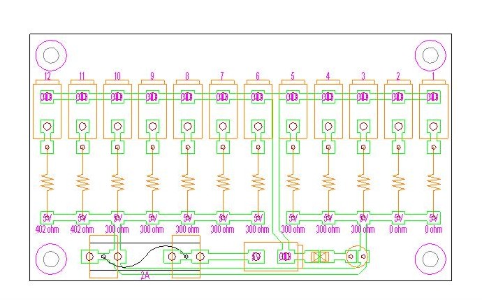
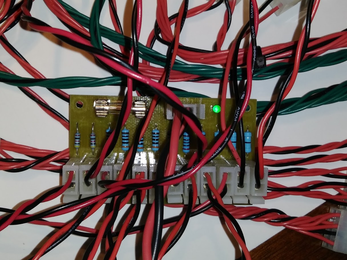
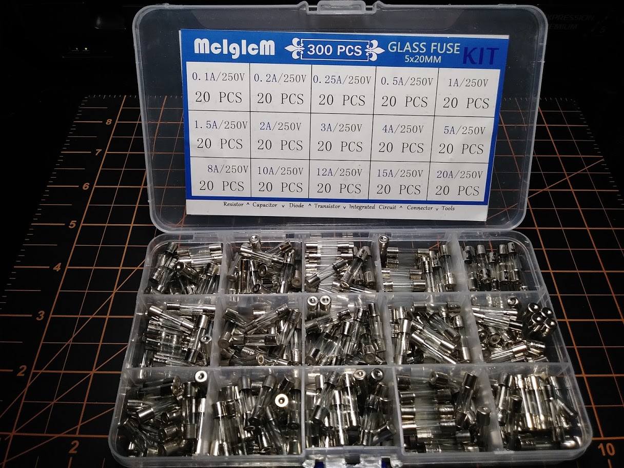
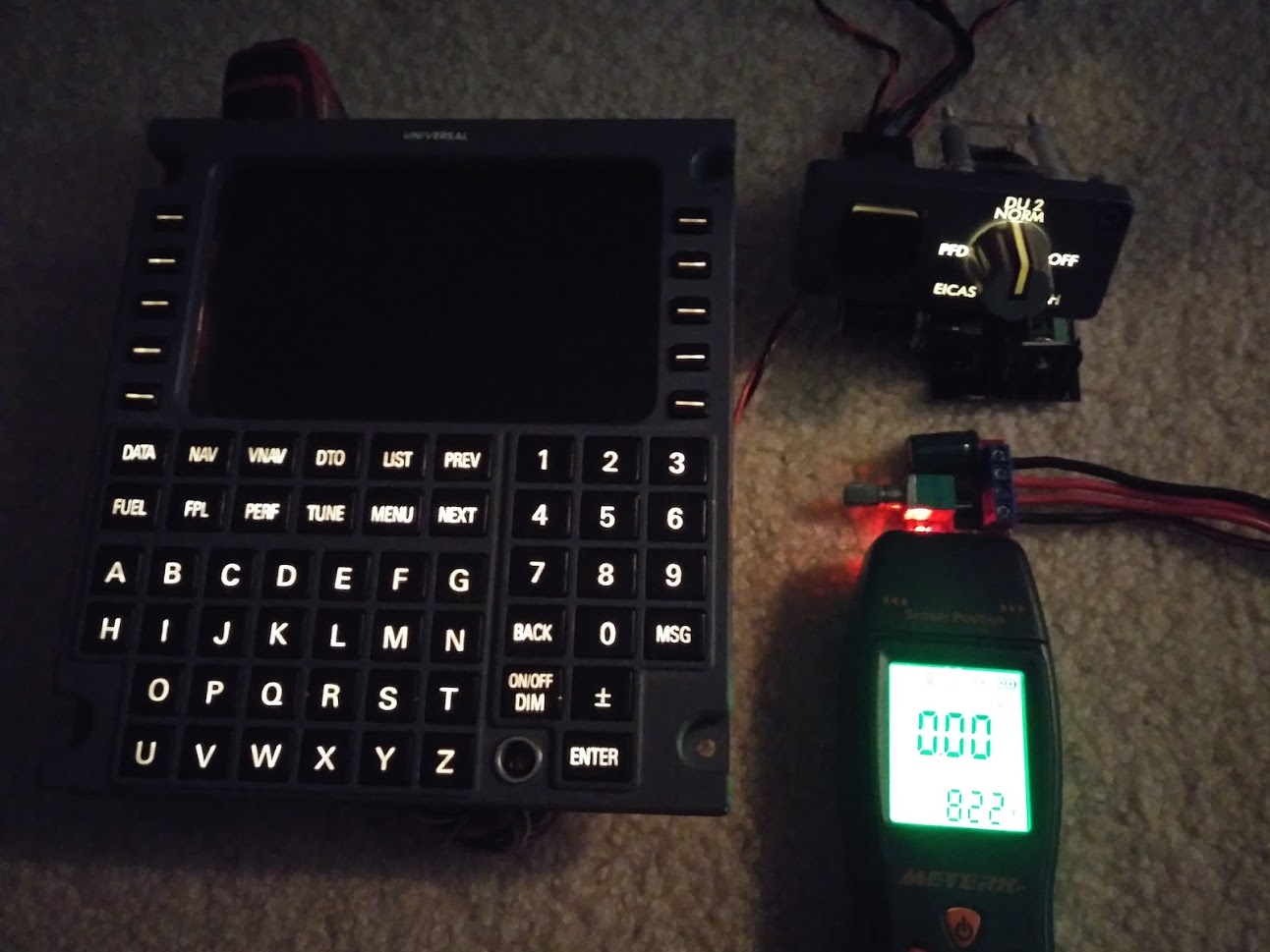
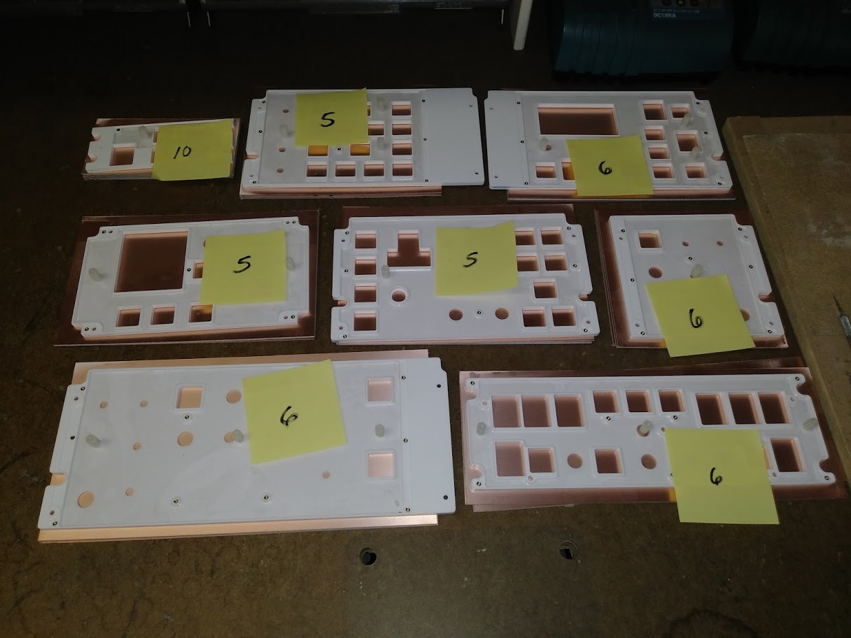
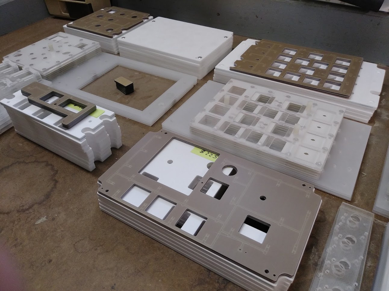
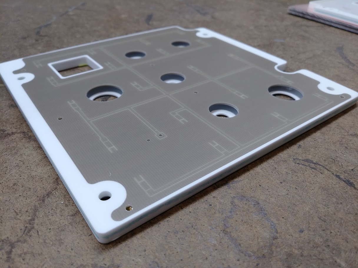
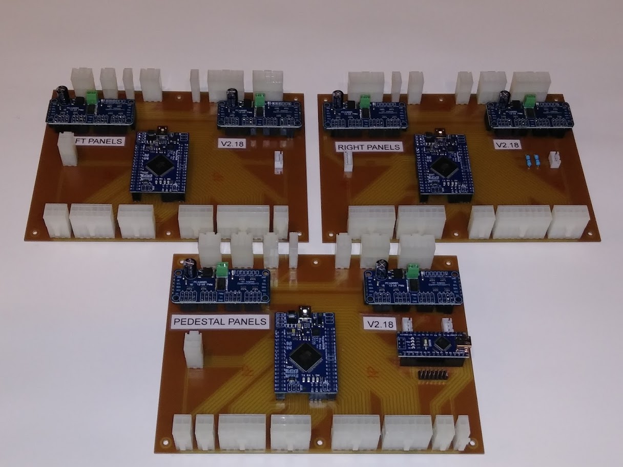
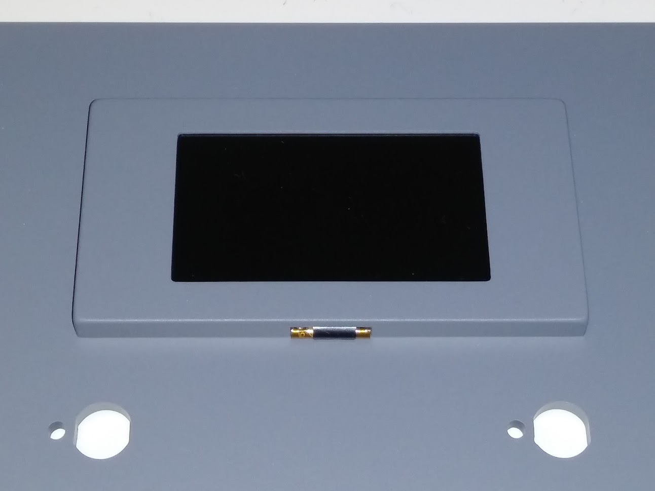
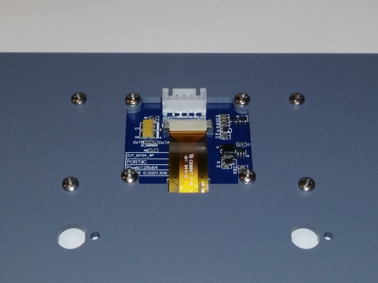
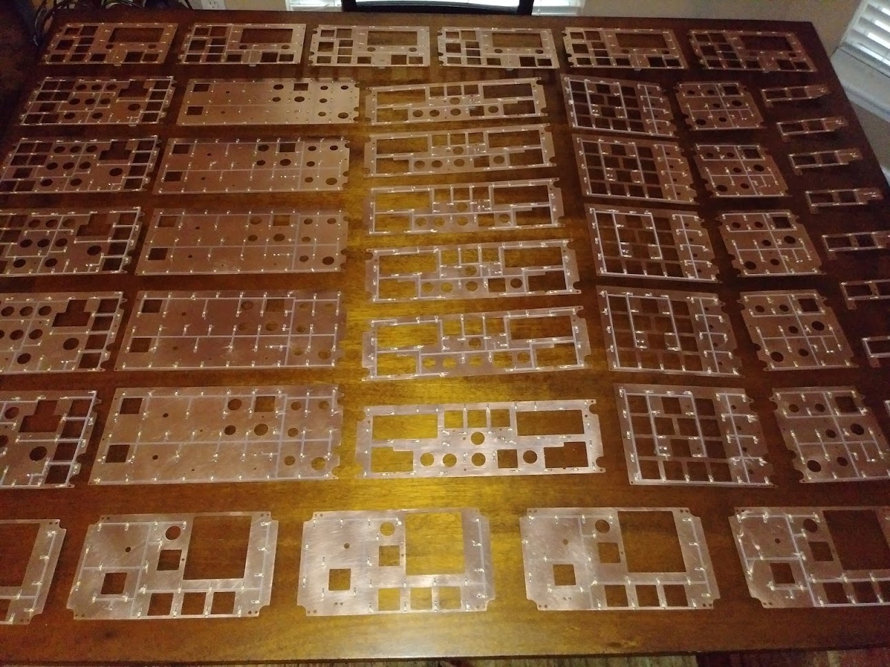
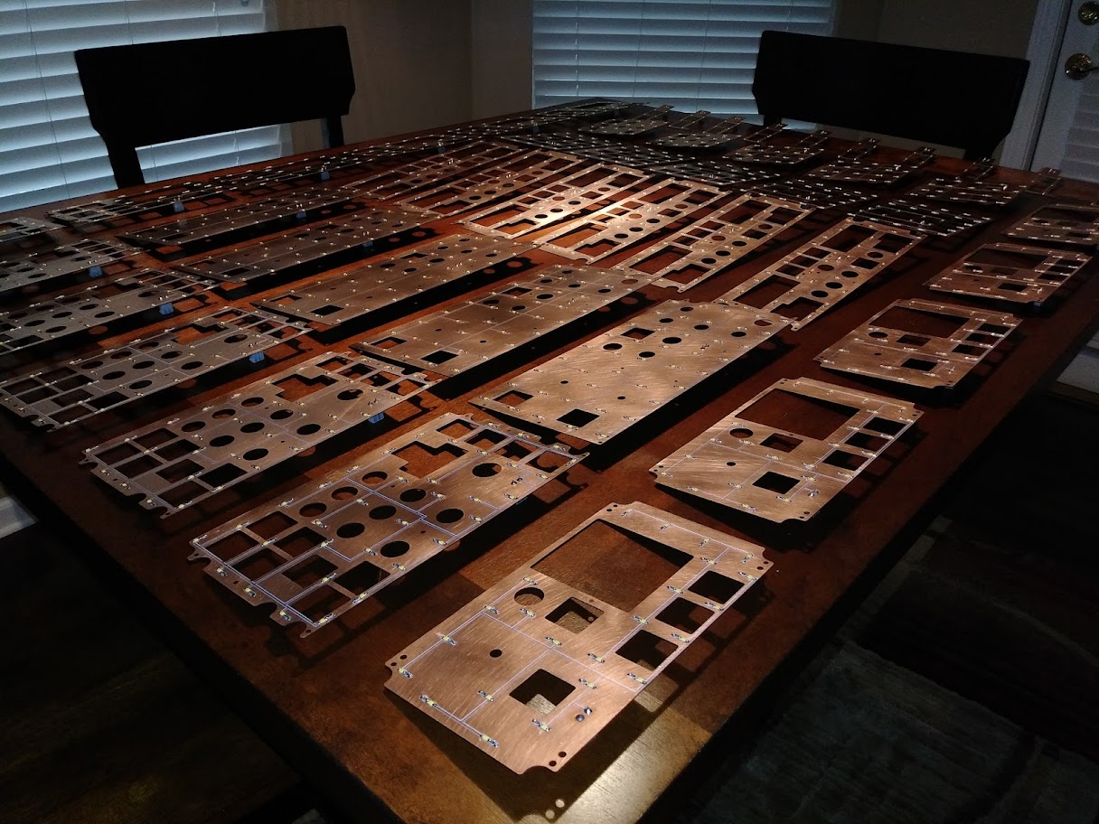
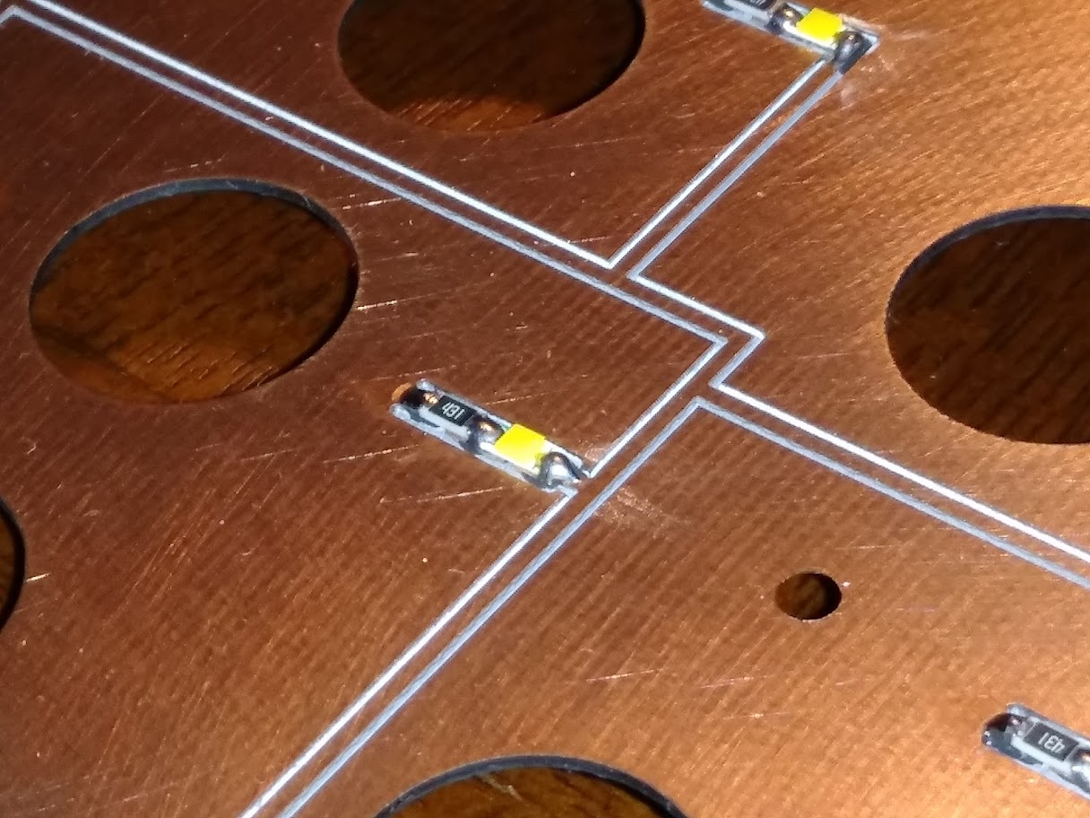
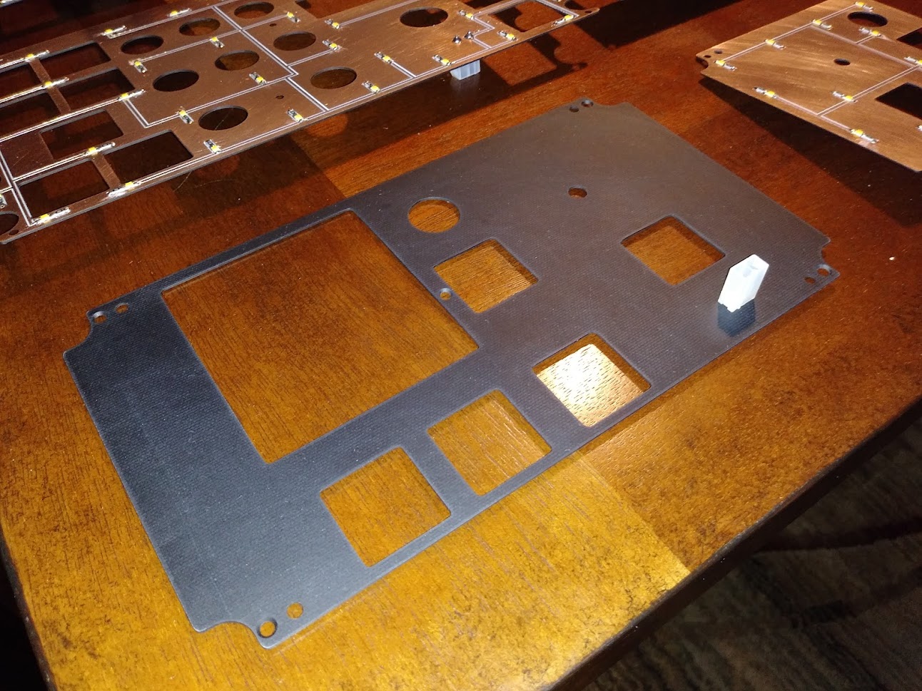
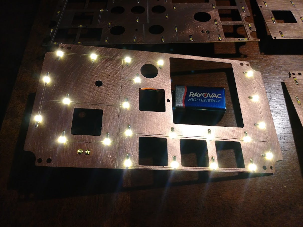
Hey Roel. Yes, it is an OLED Yellow 2.42" display. Jason's Jet45 Systems Software will take care of the graphics on the display so no worries there. I have just about got the Pressure panel proven. All I still need to do is build the clad plate and double check the artwork. Once I do that I can send you the files if you want to build your own. Hey Roel. Yes, it is an OLED Yellow 2.42" display. Jason's Jet45 Systems Software will take care of the graphics on the display so no worries there. I have just about got the Pressure panel proven. All I still need to do is build the clad plate and double check the artwork. Once I do that I can send you the files if you want to build your own. Another quick update on the new v2.0 panels and hardware! Jason and I came up with the idea of developing what we have nicknamed the "Airplane Panel". It is a hidden behind the Weight Chart panel and I have designed it so that if for some reason, you do not like this idea or want to move this panel to your instructor station, you can with no issues. As a matter of fact, it might be a good idea to have the Airplane Panel in both locations, behind the Weight Chart Panel and at your instructor station. This Airplane panel has 20 momentary push buttons each with it's own built in LED indicator. Each one of these buttons are a Reset/Status for each of the 20 Arduino Interface modules in the simulator. If each of the Arduino Interface modules are functioning properly, they will be flashing a steady heart beat pulse. If there is an issue, the individual Reset/Status will either be dark or solid. By pushing the button in question, it will reset the Arduino Module and correct the issue on the fly. If you have a perfect flight, you will not have to pop the cover off of the Airplane Panel. But if you have been in flight sim for any length of time, you are aware that anything can happen. By having this panel right at our fingertips, it will minimize the adverse effects of pausing the sim, and resetting a module outside of the sim. This photo shows the Airshow Panel in the stowed position. I have designed it so that it is basically a hidden and could possibly be considered a secret panel! I have designed the Weight Chart Panel to be held in place with a couple magnets, four in all. Two embedded into the Weight Chart Panel and two embedded into the Left Crew Backer Panel: The magnets are very strong and will hold the Weight Chart panel in place with no issues. Take a peek of the back side and see what's going on. The idea of the Airplane Panel of course came after I had four brand new MIP v2.0's cut out. So I had to create a template and a jig to manually cut the twenty holes into the aluminum MIP. Not hard, just takes some time. All these files will be available here in the hangar so you can modify your v1.0 MIPs if you wish. Wondering how the Airplane Panel got it's name? Watch this short 23 second video: https://youtu.be/CfC0V0ivNCM Another quick update on the new v2.0 panels and hardware! Jason and I came up with the idea of developing what we have nicknamed the "Airplane Panel". It is a hidden behind the Weight Chart panel and I have designed it so that if for some reason, you do not like this idea or want to move this panel to your instructor station, you can with no issues. As a matter of fact, it might be a good idea to have the Airplane Panel in both locations, behind the Weight Chart Panel and at your instructor station. This Airplane panel has 20 momentary push buttons each with it's own built in LED indicator. Each one of these buttons are a Reset/Status for each of the 20 Arduino Interface modules in the simulator. If each of the Arduino Interface modules are functioning properly, they will be flashing a steady heart beat pulse. If there is an issue, the individual Reset/Status will either be dark or solid. By pushing the button in question, it will reset the Arduino Module and correct the issue on the fly. If you have a perfect flight, you will not have to pop the cover off of the Airplane Panel. But if you have been in flight sim for any length of time, you are aware that anything can happen. By having this panel right at our fingertips, it will minimize the adverse effects of pausing the sim, and resetting a module outside of the sim. This photo shows the Airshow Panel in the stowed position. I have designed it so that it is basically a hidden and could possibly be considered a secret panel! I have designed the Weight Chart Panel to be held in place with a couple magnets, four in all. Two embedded into the Weight Chart Panel and two embedded into the Left Crew Backer Panel: The magnets are very strong and will hold the Weight Chart panel in place with no issues. Take a peek of the back side and see what's going on. The idea of the Airplane Panel of course came after I had four brand new MIP v2.0's cut out. So I had to create a template and a jig to manually cut the twenty holes into the aluminum MIP. Not hard, just takes some time. All these files will be available here in the hangar so you can modify your v1.0 MIPs if you wish. Wondering how the Airplane Panel got it's name? Watch this short 23 second video: So very clever Ron! I suspect if you fly around with the cover panel off, you'd have the same reaction! Beeping and Flashing and Beeping.... So very clever Ron! I suspect if you fly around with the cover panel off, you'd have the same reaction! Beeping and Flashing and Beeping.... Looks good Ron! I like this idea. Looks good Ron! I like this idea. Here is a quick update on our latest progress with the interface modules! To date, this is our third rendition of the prototype interface modules for the Jet45 AAS v2.0 This latest version includes reset/status buttons and plugs that can be remotely mounted. See my post #12 in this thread to get an idea of one of the places these reset buttons can be mounted. Below is a photo of the complete set of prototype interface modules for the up and coming Jet45 AAS V2.0 This is just a cool photo I wanted to share with you of the FGC module lit up from behind checking for clear trace lines and in this case they are all clean as a whistle! The final version of all our interface modules will be professionally made PCBs. However, if you are a DIY kind of guy and enjoy making your own modules using clad, 100% of all the DXF and G-code files will be available in the BUILDER RESOURCES page. Both the PCB and the clad versions will operate exactly the same, the only note worthy difference is that the clad version will have a larger footprint when compared to the PCB versions. The illustration below was created by Jason but worth posting it up here as well to give you guys a bit of a signal flow map of the Jet45 AAS and the future Jet45 Systems Software: Much more to come, just a couple sneak peaks at the progress! Here is a quick update on our latest progress with the interface modules! To date, this is our third rendition of the prototype interface modules for the Jet45 AAS v2.0 This latest version includes reset/status buttons and plugs that can be remotely mounted. See my post #12 in this thread to get an idea of one of the places these reset buttons can be mounted. Below is a photo of the complete set of prototype interface modules for the up and coming Jet45 AAS V2.0 This is just a cool photo I wanted to share with you of the FGC module lit up from behind checking for clear trace lines and in this case they are all clean as a whistle! The final version of all our interface modules will be professionally made PCBs. However, if you are a DIY kind of guy and enjoy making your own modules using clad, 100% of all the DXF and G-code files will be available in the BUILDER RESOURCES page. Both the PCB and the clad versions will operate exactly the same, the only note worthy difference is that the clad version will have a larger footprint when compared to the PCB versions. The illustration below was created by Jason but worth posting it up here as well to give you guys a bit of a signal flow map of the Jet45 AAS and the future Jet45 Systems Software: Much more to come, just a couple sneak peaks at the progress! That looks really really good Ron!!! That looks really really good Ron!!! "Let there be light............" Okay, it was actually one single LED with a 200 Ohm resistor powered by a 9 volt battery! This is where it started for me personally several years ago when I was looking into what it would take to back light our Lear45 panels. Today after many trials and errors I am happy to say that we now have a solid solution forward. Below is an example of our back lighting tested, tamed and under control! The path that we have been on for the past year has not changed, however, there was a minor hiccup the other day when I was doing some research related to the effects of EMI within our sims. You can read more about the EMF/EMI issues and solutions HERE During the EMI testing, I accidentally smoke checked my LCU Module (Light Control Unit) prototype when I touched a positive wire directly to a ground wire. The photo below shows the repair I made to one of the copper clad trace lines. This got me to thinking we need to add some protection to these LCU modules in the form of a 3x20mm fuse. This was also the perfect time to add a small indicator LED to the LCU module. Below is the new LCU module next to the old design. The glass fuse insures what happened above will never happen again. Worse case, the fuse blows! As mentioned in an earlier post, the LCU modules are designed to "massage" the voltage so that you can perfectly match the intensity of all the panels within that channel, no matter if they are incandescent bulbs or LED! A closer look at the new LCU module design. The LCU module design is fairly simple. There is a plug at the bottom center where the 5 volt power comes into the module and then it runs through the fuse. From there, power flows though the 12 individual resistors that value from 0 Ohm up to 430 Ohm depending on the panel it's supplying power to. And from there to the plugs at the top of the module which run off to the individual panels. NOTE: The resistor values above are for the resistors mounted on the LCU module. All panels that are LED backlit have 430 ohm SMD resistors for each LED on the individual panels. As an example, the are 31 LEDs on the Project45 Pressure Panel and each one of those LEDs has it's own 430 ohm SMD resistor to drop the voltage down to a safe level to handle up to 12 volt power. Anything more than 12 volts and the LEDs will fail. (To be clear, we are using 5 volt power) Here is the LCU prototype in action! I have a mix match of LED panels with three incandescent bulb panels, the CDU and two Davtron clocks. This is the best I can do with the panels I have on hand ATM to replicate a load on the LCU prototype. After doing some extensive testing, I have determined that the Left and Right LCU modules call for a 2A fuse. The Pedestal LCU will require a 4A fuse if you are using dual real CDUs with 5V incandescent bulbs. (Each CDU draws just under 1.5A at 5 volts.) So if you are going to use a dual CDU setup, you will want to use a 4A fuse on the Pedestal LCU module. A single CDU setup will require a 3A fuse on the Pedestal LCU module. However, if replica CDUs are made using LEDs for the back lighting, a 2A fuse is all that is required on the Pedestal LCU module. I found a 300 piece fuse kit that had several low fuse values starting at .1A up to 20A for less than $15. The size fuse that the LCUs will take are the 5X20mm. One last very important point is that this back lighting solution does not emit any EMI that I am able to detect. This system appears to be as clean as a whistle! I am very excited about where we are with the back lighting solution. After several hours of continuous testing, all indications are we have a solid plan forward. In the meantime, I will be getting back to work on the current batch of panels that have been sitting idle for way too long! "Let there be light............" Okay, it was actually one single LED with a 200 Ohm resistor powered by a 9 volt battery! This is where it started for me personally several years ago when I was looking into what it would take to back light our Lear45 panels. Today after many trials and errors I am happy to say that we now have a solid solution forward. Below is an example of our back lighting tested, tamed and under control! The path that we have been on for the past year has not changed, however, there was a minor hiccup the other day when I was doing some research related to the effects of EMI within our sims. You can read more about the EMF/EMI issues and solutions HERE During the EMI testing, I accidentally smoke checked my LCU Module (Light Control Unit) prototype when I touched a positive wire directly to a ground wire. The photo below shows the repair I made to one of the copper clad trace lines. This got me to thinking we need to add some protection to these LCU modules in the form of a 3x20mm fuse. This was also the perfect time to add a small indicator LED to the LCU module. Below is the new LCU module next to the old design. The glass fuse insures what happened above will never happen again. Worse case, the fuse blows! As mentioned in an earlier post, the LCU modules are designed to "massage" the voltage so that you can perfectly match the intensity of all the panels within that channel, no matter if they are incandescent bulbs or LED! A closer look at the new LCU module design. The LCU module design is fairly simple. There is a plug at the bottom center where the 5 volt power comes into the module and then it runs through the fuse. From there, power flows though the 12 individual resistors that value from 0 Ohm up to 430 Ohm depending on the panel it's supplying power to. And from there to the plugs at the top of the module which run off to the individual panels. NOTE: The resistor values above are for the resistors mounted on the LCU module. All panels that are LED backlit have 430 ohm SMD resistors for each LED on the individual panels. As an example, the are 31 LEDs on the Project45 Pressure Panel and each one of those LEDs has it's own 430 ohm SMD resistor to drop the voltage down to a safe level to handle up to 12 volt power. Anything more than 12 volts and the LEDs will fail. (To be clear, we are using 5 volt power) Here is the LCU prototype in action! I have a mix match of LED panels with three incandescent bulb panels, the CDU and two Davtron clocks. This is the best I can do with the panels I have on hand ATM to replicate a load on the LCU prototype. After doing some extensive testing, I have determined that the Left and Right LCU modules call for a 2A fuse. The Pedestal LCU will require a 4A fuse if you are using dual real CDUs with 5V incandescent bulbs. (Each CDU draws just under 1.5A at 5 volts.) So if you are going to use a dual CDU setup, you will want to use a 4A fuse on the Pedestal LCU module. A single CDU setup will require a 3A fuse on the Pedestal LCU module. However, if replica CDUs are made using LEDs for the back lighting, a 2A fuse is all that is required on the Pedestal LCU module. I found a 300 piece fuse kit that had several low fuse values starting at .1A up to 20A for less than $15. The size fuse that the LCUs will take are the 5X20mm. One last very important point is that this back lighting solution does not emit any EMI that I am able to detect. This system appears to be as clean as a whistle! I am very excited about where we are with the back lighting solution. After several hours of continuous testing, all indications are we have a solid plan forward. In the meantime, I will be getting back to work on the current batch of panels that have been sitting idle for way too long! The past week or so I have been busy working on this current batch of 55 panels that mostly comprise of the lower panels. There are only a few steps left to complete them and I plan to stick with them until they are finished. (Unless something of greater importance pops up) The biggest job was to cut the single sided clad on all the panels. I cut all the clad out prior so that I knew exactly how much material I would need for all the clad pieces. Here is a photo of half the clad cut and ready for final sanding and painting. All the clad is designed to fit embedded into the back side of the front panel. I create the G-code with a 1/16" bit to do the final outside cuts and around the AML holes, but I actually use a 3/32" bit to do the cutting. This enables me to fit the clad into the socket on the back side of the front panel which insures no light bleed. The next week or two will be all about sanding and painting. More updates soon! The past week or so I have been busy working on this current batch of 55 panels that mostly comprise of the lower panels. There are only a few steps left to complete them and I plan to stick with them until they are finished. (Unless something of greater importance pops up) The biggest job was to cut the single sided clad on all the panels. I cut all the clad out prior so that I knew exactly how much material I would need for all the clad pieces. Here is a photo of half the clad cut and ready for final sanding and painting. All the clad is designed to fit embedded into the back side of the front panel. I create the G-code with a 1/16" bit to do the final outside cuts and around the AML holes, but I actually use a 3/32" bit to do the cutting. This enables me to fit the clad into the socket on the back side of the front panel which insures no light bleed. The next week or two will be all about sanding and painting. More updates soon! Quick update on the v2.0 panels and modules! We are ramping up efforts to do further beta testing on the Jet45 Systems Software modules. As a reminder, the Jet45 Systems Software is designed to handle EVERYTHING else in the sim that the Jet45 Advanced Avionics Suite does not take care of with the exception of the main flight controls. The flight controls will be handled via a couple Leo Bodnar BU0836 cards. You can find the latest updated Jet45 AAS Systems Modules document HERE Here is a photo of the three Panels Modules in clad form. The final products will be pcb version: These modules are designed to handle all LED indications, switches, pots, encoders, a couple displays, you name it and all powered via Arduino interface cards. A big thanks to Jason Hite for making this all happen. Without his talents and work, none of this would be possible! Additionally, here are a couple detailed photos of the completed pressure display window. The display is a 128x64 resolution yellow OLED screen. The physical dimensions of the pressure display frame and window are true to scale. Jason's software development has found that the OLED display is the easiest to interface with the Arduino and the performance is much better than a TFT LCD display. The installation into the designed backer is super clean! In other news, all but just a couple panels have been sanded and are ready for paint. Look for an update next week on that! Quick update on the v2.0 panels and modules! We are ramping up efforts to do further beta testing on the Jet45 Systems Software modules. As a reminder, the Jet45 Systems Software is designed to handle EVERYTHING else in the sim that the Jet45 Advanced Avionics Suite does not take care of with the exception of the main flight controls. The flight controls will be handled via a couple Leo Bodnar BU0836 cards. You can find the latest updated Jet45 AAS Systems Modules document HERE Here is a photo of the three Panels Modules in clad form. The final products will be pcb version: These modules are designed to handle all LED indications, switches, pots, encoders, a couple displays, you name it and all powered via Arduino interface cards. A big thanks to Jason Hite for making this all happen. Without his talents and work, none of this would be possible! Additionally, here are a couple detailed photos of the completed pressure display window. The display is a 128x64 resolution yellow OLED screen. The physical dimensions of the pressure display frame and window are true to scale. Jason's software development has found that the OLED display is the easiest to interface with the Arduino and the performance is much better than a TFT LCD display. The installation into the designed backer is super clean! In other news, all but just a couple panels have been sanded and are ready for paint. Look for an update next week on that! Quick update on the panel production! I just recently completed all the clad pieces which included sanding, fitting, painting the back side and last but certainly not least, soldering 1,269 LEDs on the nearly 50 panels! That's right, in all there were 3,902 soldering points after including the SMD resistors and plugs. I never thought I would considered myself a professional solderer but after this run, I think I am there. Take a look at this mother load of clad! The Environmental panel currently holds the record with the most LEDs and that is 43. The CB panels will certainly beat that! The size of these SMD LEDs and resistors are 1207. They are not the smallest SMDs but small they are. The back side of all the clad was painted in flat black to give a finished look and to block the light from within from shining through the trace lines. All the panels are equipped with 430 ohm resistors for each individual LED. The panels are designed to use 5 volt power for the perfect maximum intensity when used in conjunction with the LCUs. (see above post for more details) However, the panels can safely use power up to 12 volts without damaging the LEDs. Notice in this photo I am using a 9 volt battery to test the panel. During the testing process to insure all LEDs are working properly, the clad is tapped, dropped and flexed to insure there are no dead solder points. Out of nearly 4,000 soldering joints, I only had two that needed a little extra attention. I also had two LEDs that were flipped. Not to bad. The final stretch includes masking off the front panels, painting the front panels and engraving the front panels. A lot of work but well worth the effort! Quick update on the panel production! I just recently completed all the clad pieces which included sanding, fitting, painting the back side and last but certainly not least, soldering 1,269 LEDs on the nearly 50 panels! That's right, in all there were 3,902 soldering points after including the SMD resistors and plugs. I never thought I would considered myself a professional solderer but after this run, I think I am there. Take a look at this mother load of clad! The Environmental panel currently holds the record with the most LEDs and that is 43. The CB panels will certainly beat that! The size of these SMD LEDs and resistors are 1207. They are not the smallest SMDs but small they are. The back side of all the clad was painted in flat black to give a finished look and to block the light from within from shining through the trace lines. All the panels are equipped with 430 ohm resistors for each individual LED. The panels are designed to use 5 volt power for the perfect maximum intensity when used in conjunction with the LCUs. (see above post for more details) However, the panels can safely use power up to 12 volts without damaging the LEDs. Notice in this photo I am using a 9 volt battery to test the panel. During the testing process to insure all LEDs are working properly, the clad is tapped, dropped and flexed to insure there are no dead solder points. Out of nearly 4,000 soldering joints, I only had two that needed a little extra attention. I also had two LEDs that were flipped. Not to bad. The final stretch includes masking off the front panels, painting the front panels and engraving the front panels. A lot of work but well worth the effort!V2.0 Panel Progress by Project45
![]()
![]()
![]()
![]()
![]()
![]()
![]()

![]()
![]()
![]()
Forum NavigationV2.0 Panel Progress by Project45
![]() #11 · November 12, 2020, 9:09 pmrtmtech has reacted to this post.rtmtech
#11 · November 12, 2020, 9:09 pmrtmtech has reacted to this post.rtmtech![]() #12 · November 22, 2020, 4:59 pm
#12 · November 22, 2020, 4:59 pm![]() #13 · November 23, 2020, 12:53 amJason Hite
FlightDeckSoft
#13 · November 23, 2020, 12:53 amJason Hite
FlightDeckSoft![]() #14 · November 30, 2020, 5:54 pm
#14 · November 30, 2020, 5:54 pm![]() #15 · December 13, 2020, 9:22 pm
#15 · December 13, 2020, 9:22 pm![]() #16 · December 15, 2020, 6:52 pm
#16 · December 15, 2020, 6:52 pm![]() #17 · June 4, 2021, 9:58 pm
#17 · June 4, 2021, 9:58 pm![]() #18 · July 18, 2021, 1:55 pm
#18 · July 18, 2021, 1:55 pm![]() #19 · August 3, 2021, 2:27 pm
#19 · August 3, 2021, 2:27 pm![]() #20 · August 28, 2021, 10:34 pm
#20 · August 28, 2021, 10:34 pm
2017-10-10