


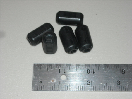
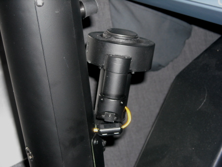
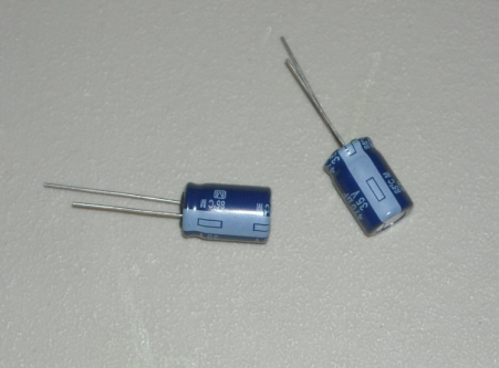
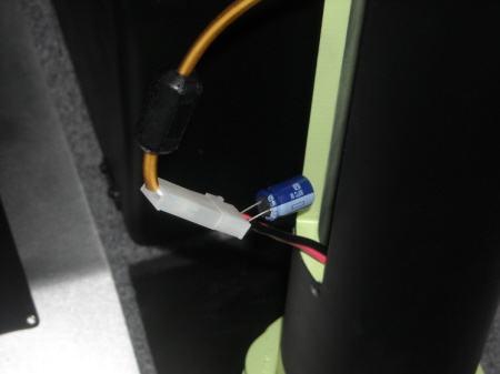
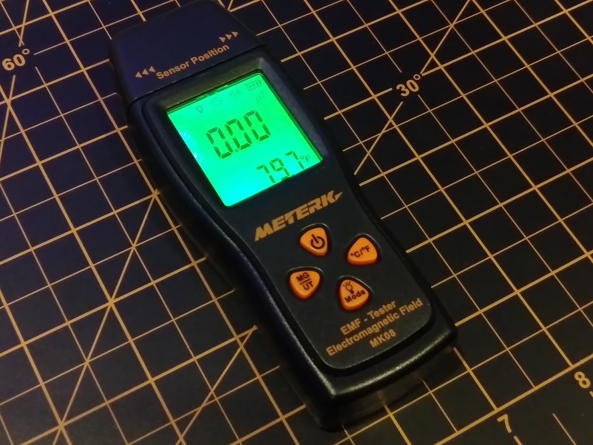
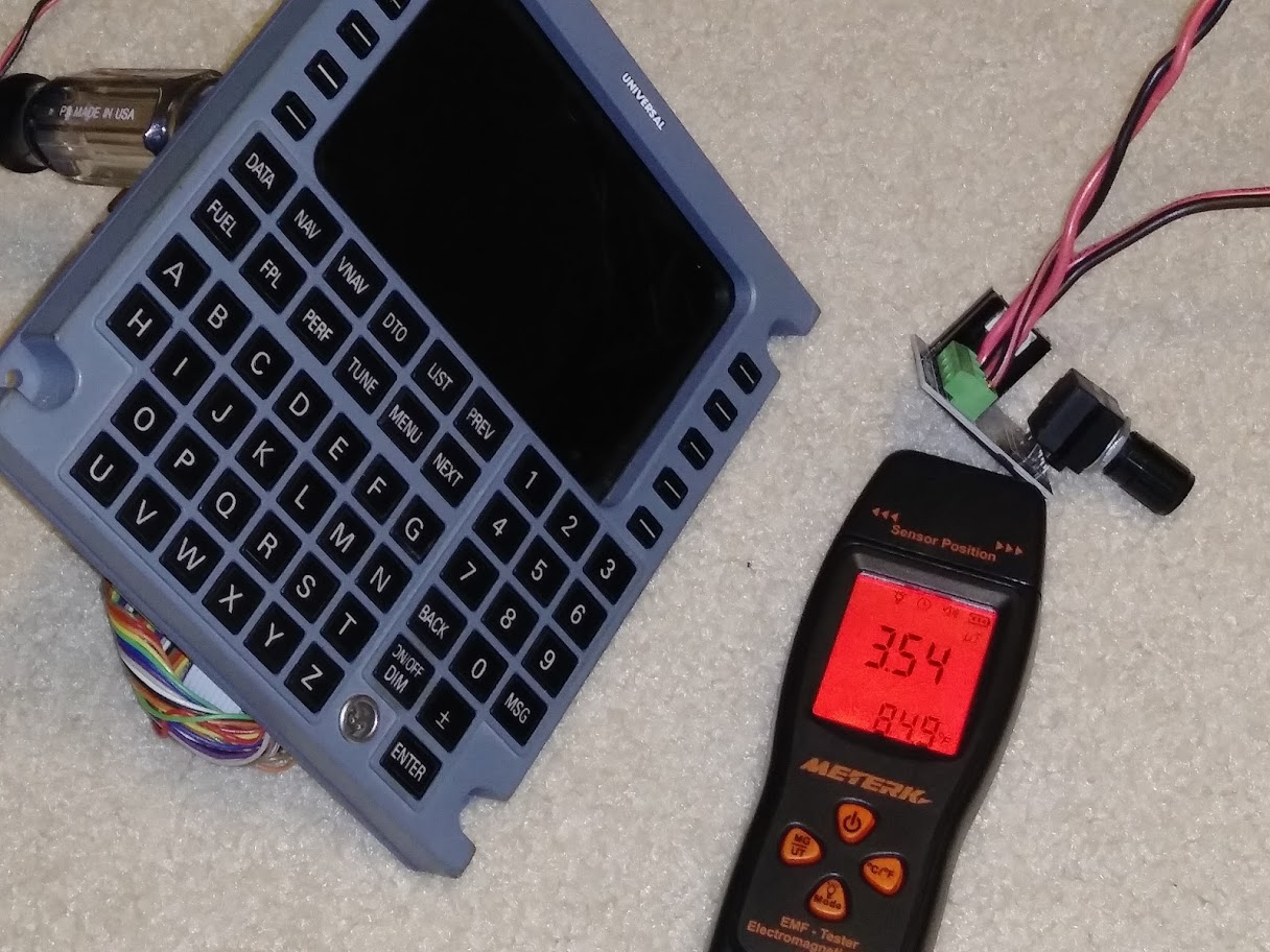
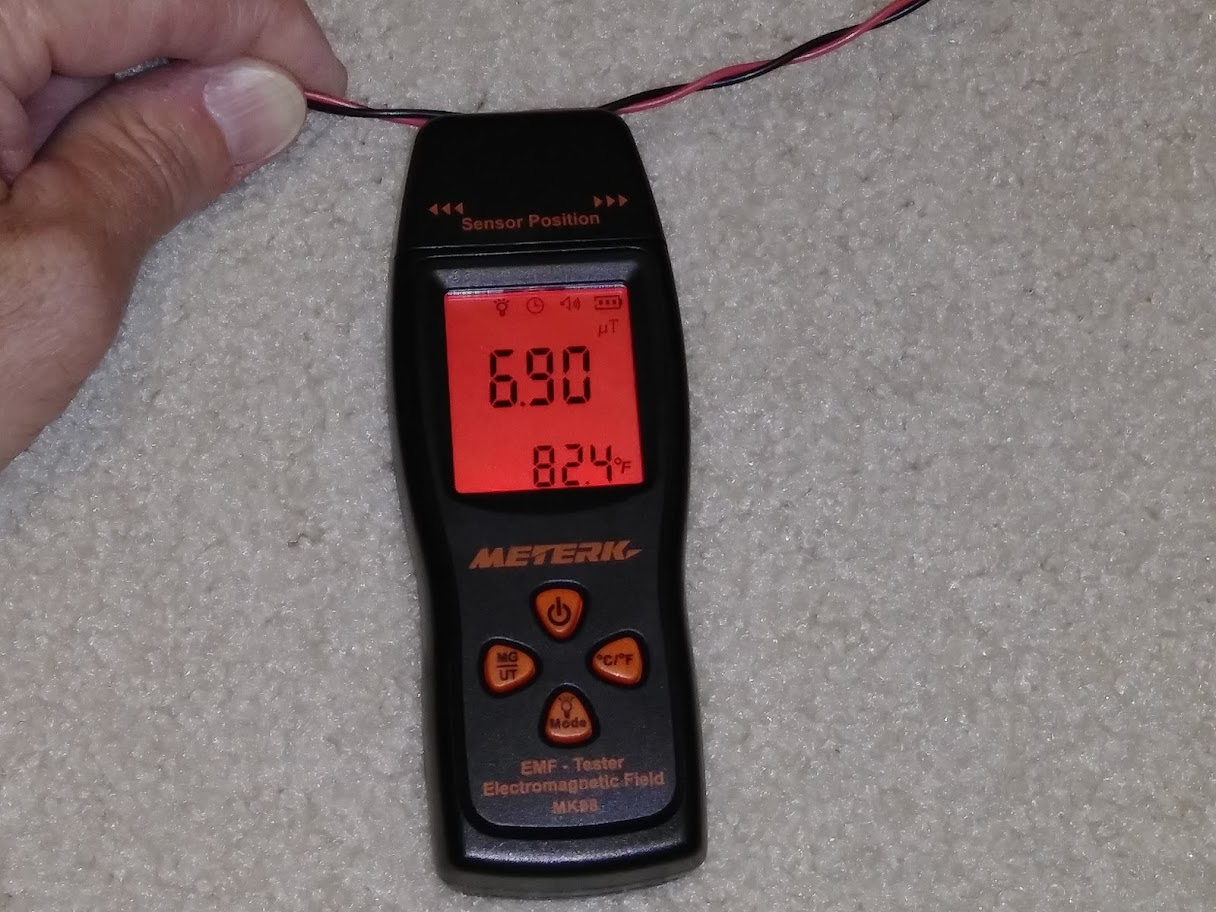
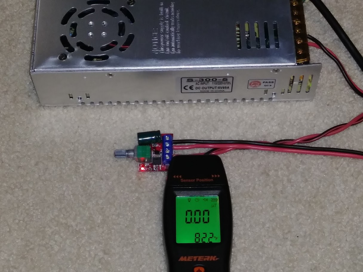
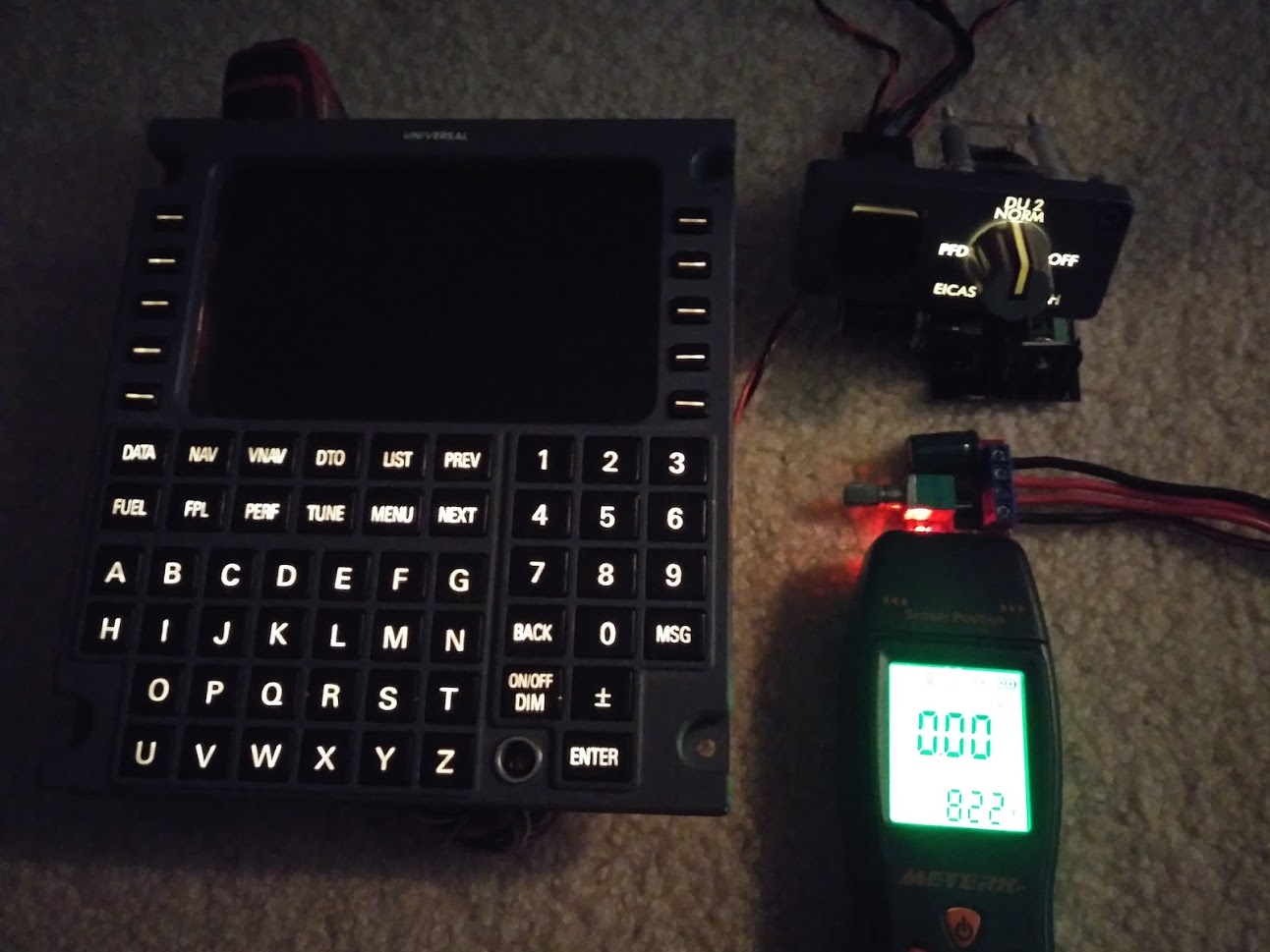
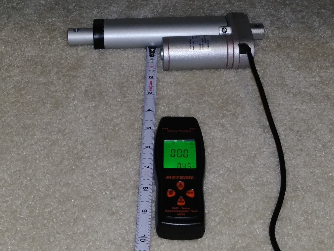
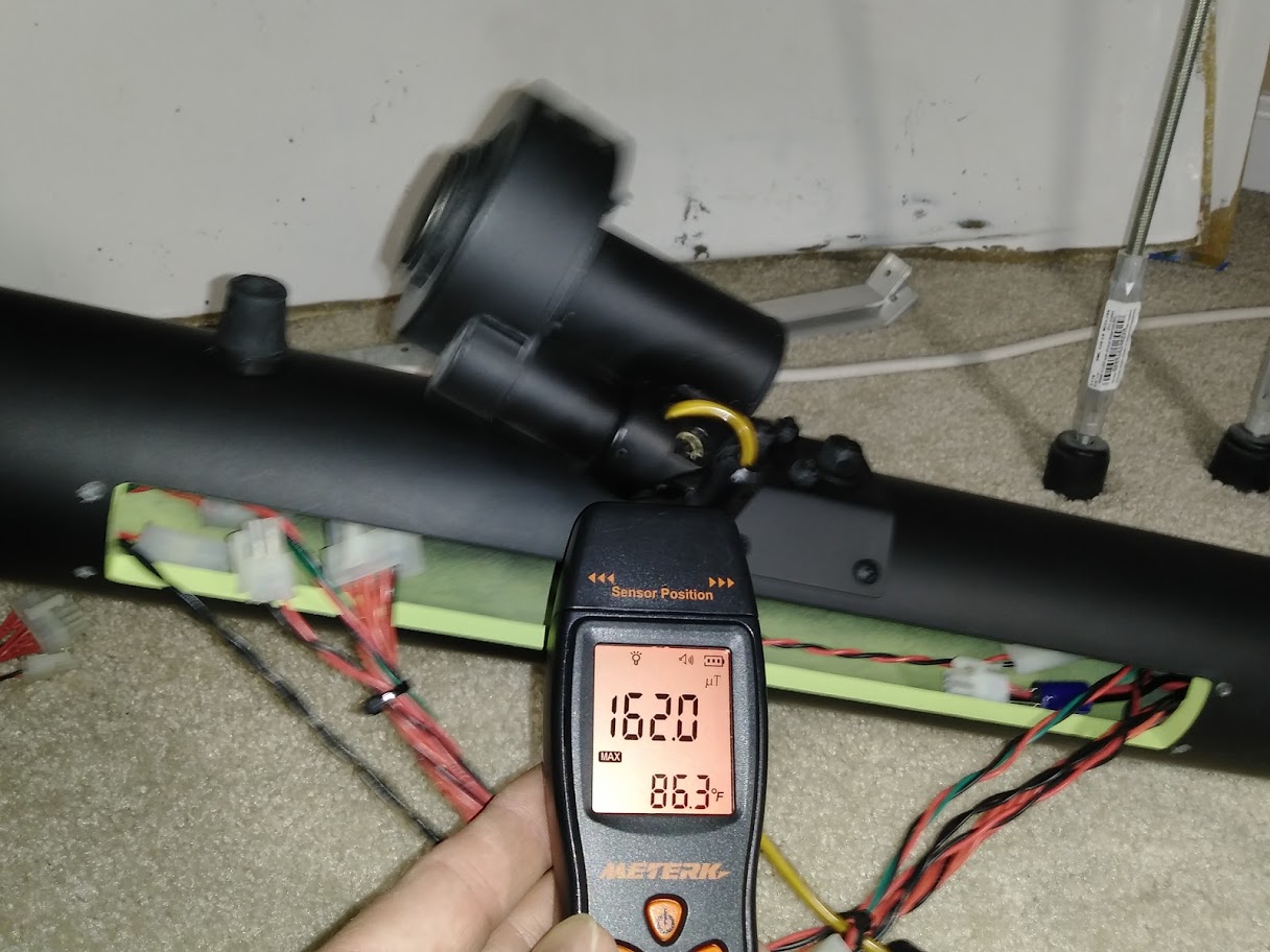
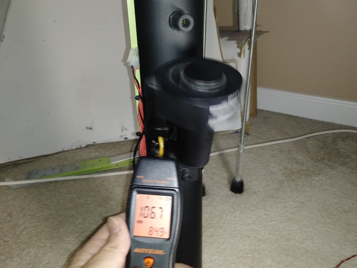
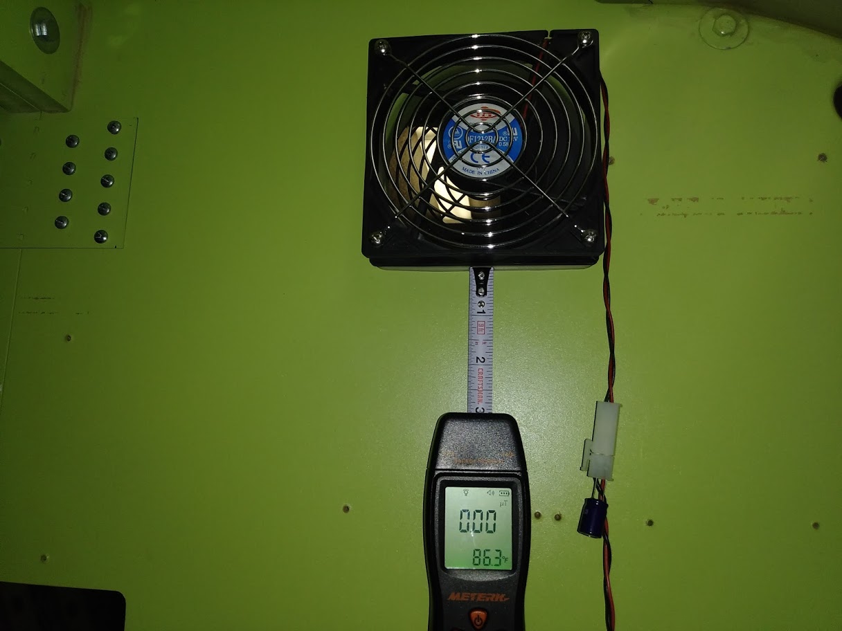
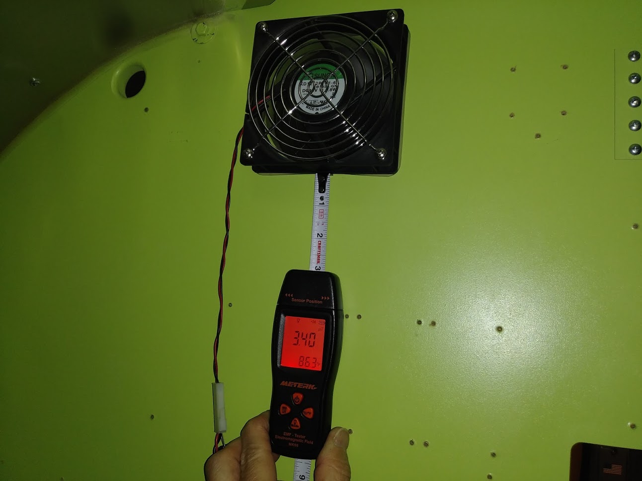
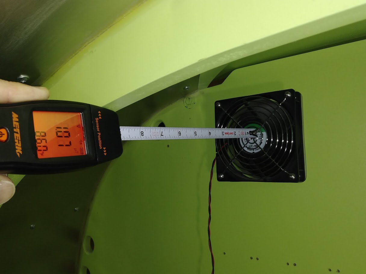
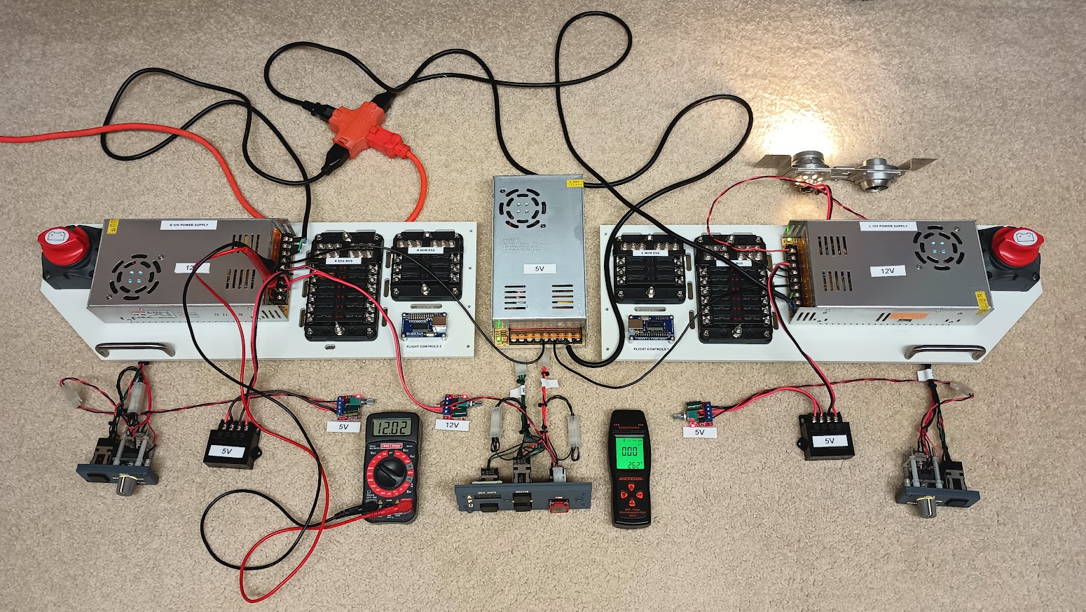
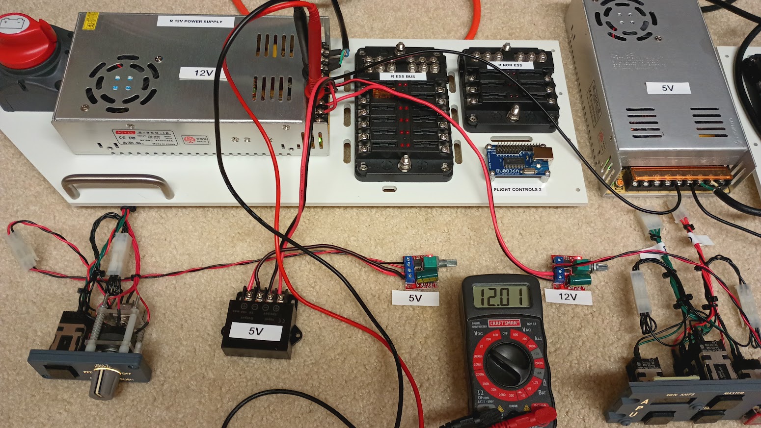
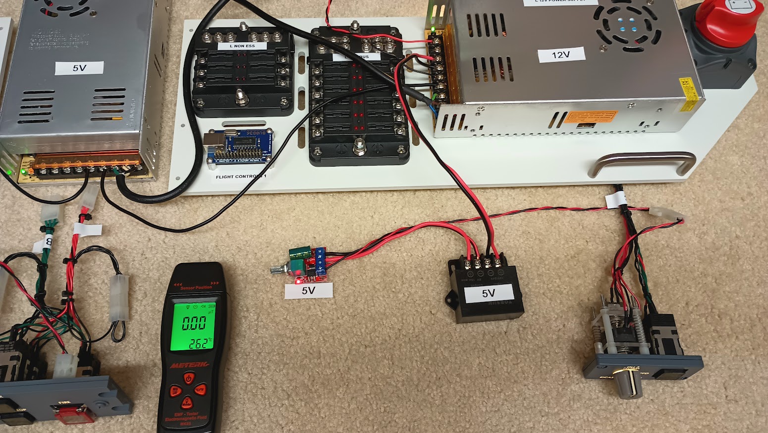
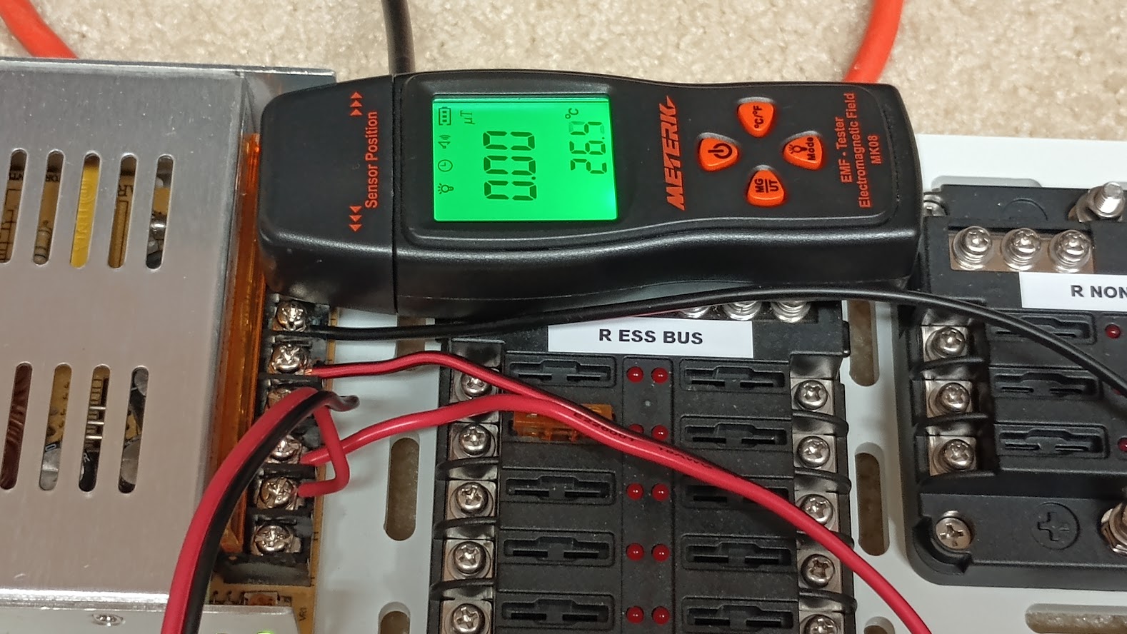
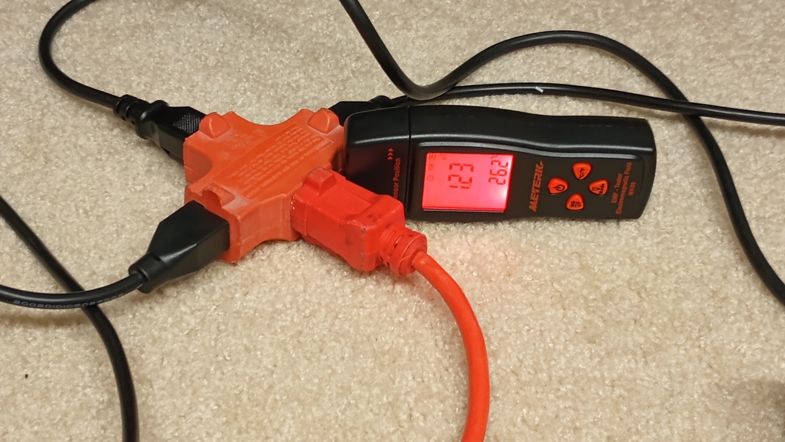
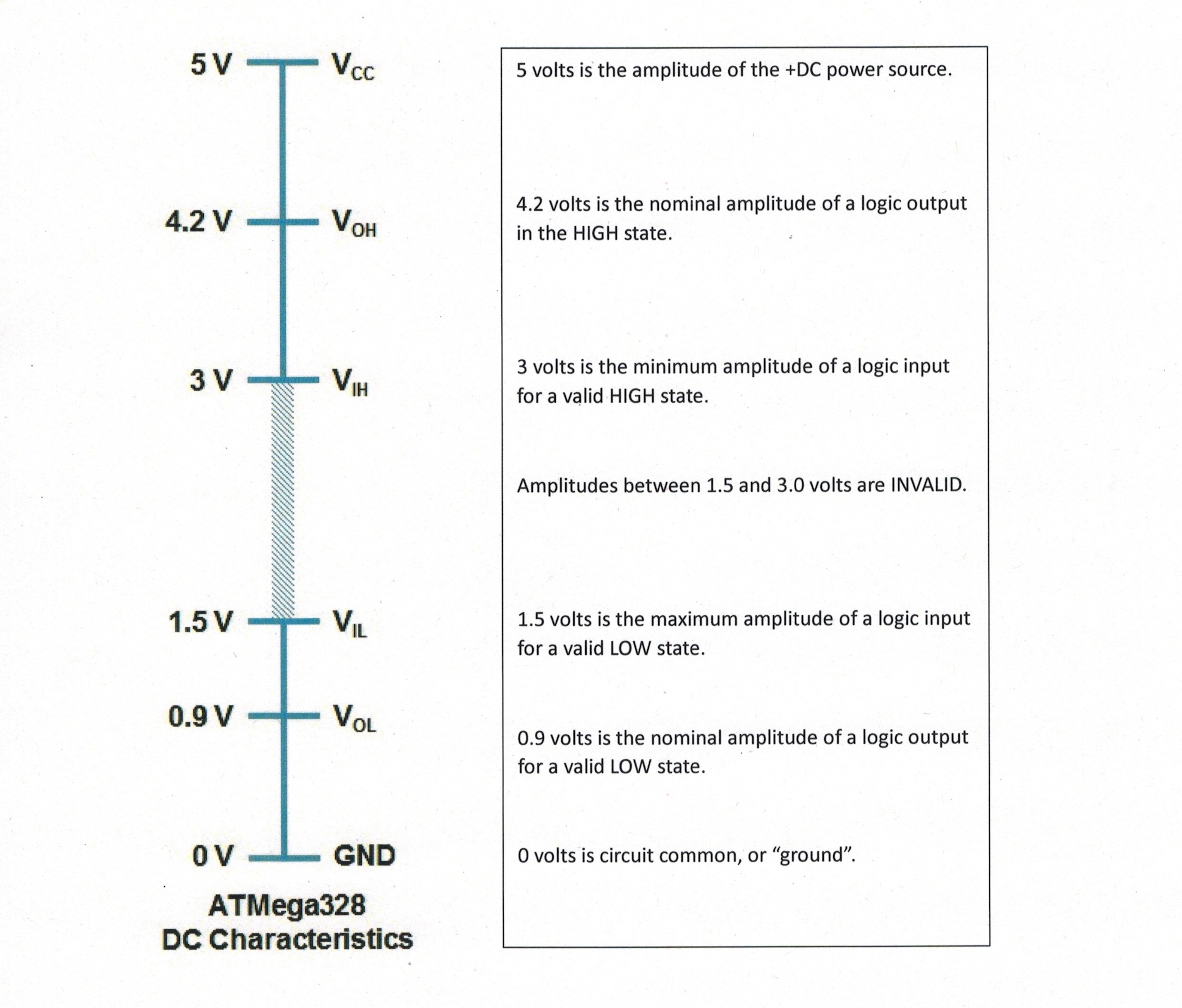
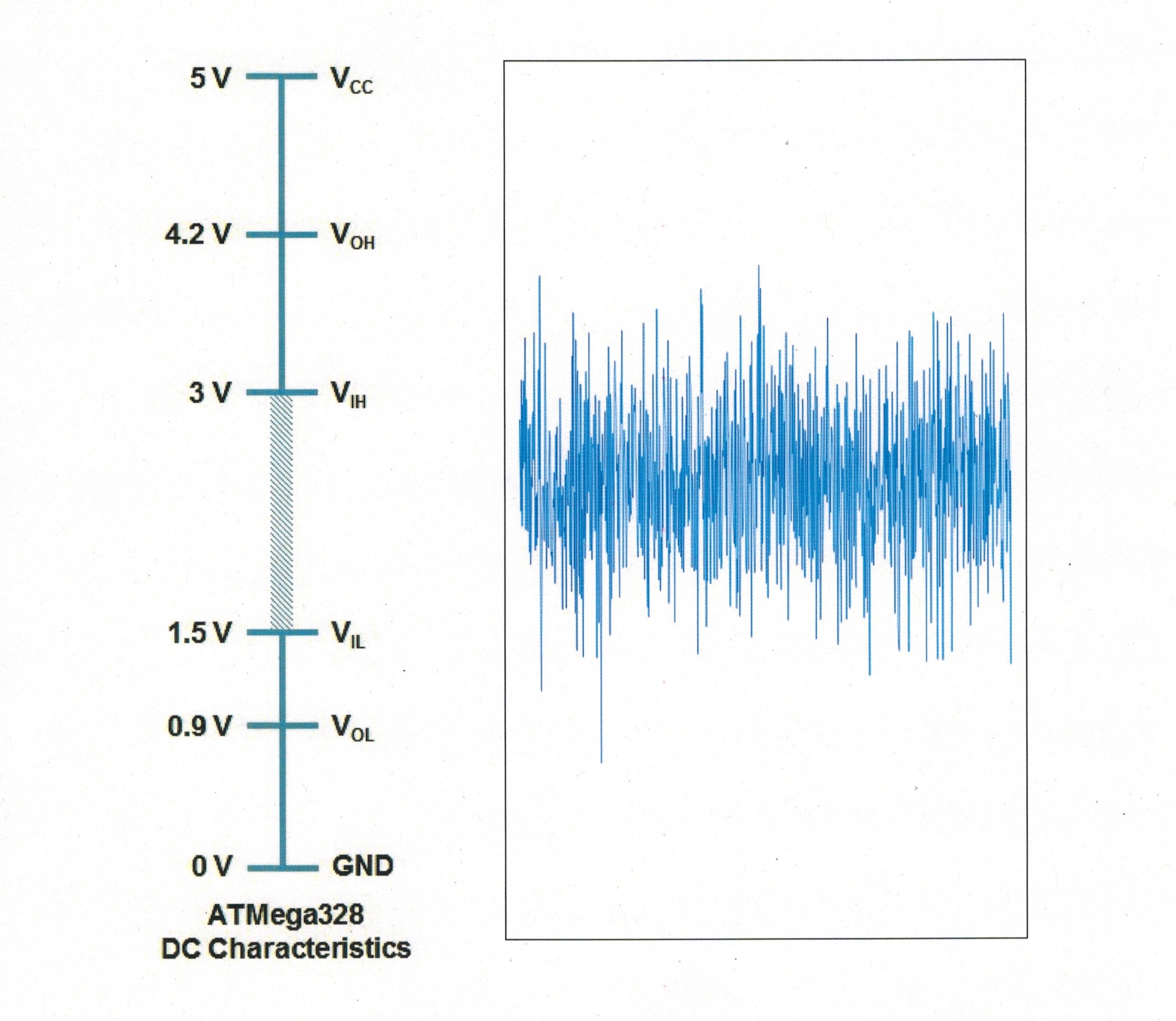
(Original thread started on 10-25-12 by Ron Rollo) The other day I was showing off all the functionality of my simulator to some local "none hangar45 friends" and had everything lit up and running great. And then I tested the stick shakers......... Activating the stick shakers caused the FDS SYS interface cards to get knocked off line and the whole cockpit went dark! How embarrassing! Anyone have any ideas as to what could cause this? (Posted by DonnyRay Jones on 10-27-12) I suspect the issue you're seeing is related to electrical noise produced by the brushes in the stick shaker motors causing your power supplies to behave erratically. I doubt it's a load current issue. All DC motors (and relays) require a reverse EMF diode to control transients on the supply line. Most motors also require an inline noise filter. If you don't have those and you are using any form of switching power supply, I'll bet a cheeseburger with onion rings the issue is EMF. (Posted by Ron Rollo on 10-27-12) Hey DonnyRay, I'll bet your right, or at least it is not a load issue. I think what was happening is that when the stick shakers were being asked to come alive, the left stick shaker was having a hard time getting started. The left power supply also controls the relay card which controls the FDS SYS card so when it looses power, both stick shakers stop working along with everything else that is receiving real 12 volt power. It sounds like what your saying is that two 30 amp power supplies should be plenty! (Posted by DonnyRay Jones on 10-28-12) Re: Power *systems*, including the power supplies associated with them: 1. Don't guess - do a load inventory. Make a list of *every* component that requires electricity. Write down the nominal load current for each component, then add them up. Rule of thumb: Your total load current should not exceed about 80% of the capacity of your power SOURCE. If you're using linear power supplies as a source, don't exceed about 60%. 2. EMI protection - you always need this even if you're running direct from batteries. EMI will get into other electronics besides power supplies (most notably "logic cards") and cause erratic behavior. The most likely source of high amplitude EMI in your cockpit is unprotected RELAYS or brush-type DC MOTORS. If a device has a coil and you operate it with DC, it requires protection or it will cause you grief. 3. What kind of protection? For relays and solenoids a reverse EMF diode connected directly across the coil is normally adequate. (Use something like a 1N4008 and observe proper polarity of the diode.) Motors are commonly equipped with a series EMI filter of appropriate rating for the voltage and current required by the load. Note that a series EMI filter is NOT a "ferrite bead" clamped around the wire. A proper series EMI filter contains one or more inductors in each line with capacitors across the in/output leads. Install it as close to the motor as practical to gain the maximum benefit from the EMI filter. (Posted by Ron Rollo on 12-08-12) Thanks DonnyRay for the info. The hard part is trying to figure out what we currently have in the sim and what we plan on having in the sim in the future. The whole project keeps growing! At this point, I am about 99% convinced that the issue is EMI and or RFI leaking into my "logic cards" as DonnyRay pointed out in post #11. The problem with my InterfaceIT getting kicked off line has nothing to do with lack of power. To learn more about Electromagnetic Interference, click here: http://en.wikipedia.org/wiki/Electromagnetic_interference I ran the column shaker power lines away from all the interface cards as best as I could in an effort to reduce the direct EMI. Now I have about a 10% failure rate when the shakers are activated either through the system test switch or an actual in flight stall. I know DonnyRay said that "ferrite bead" will do nothing for my issue, but I could not resist at only $5.99 for a set of five, and as easy as they are to use, I thought I would give them a try. DonnyRay was right. But for the sake of education here are a few photos of what RFI / EMI noise filters look like and where to get them: http://www.ebay.com/itm/160830000831?ssPageName=STRK:MEWNX:IT&_trksid=p3984.m1497.l2648 Look how easy they are to use! It's a shame that this did not solve the problem because they were as easy as 1,2,3. However, everything that I have been doing is improving the issue but like DonnyRay pointed out, it is going to take a series EMI Filter and a capacitor connected directly across the coil and as close to the column shakers as possible to finally resolve the problem, I hope. I'll let you know how that works out as soon as I get them installed! Before I place an order, I was wondering if any of you guys have about 15 feet of 18AWG two conductor shielded cable/wire that you would like to sell. http://www.ebay.com/itm/Carol-2-Conductor-Shielded-PVC-18-AWG-Wire-C2534A-41-10-/160883591130?pt=LH_DefaultDomain_0&hash=item257568c7da This is one of the best deals I could find at the best match but I don't want to spend $25 for a hundred feet of this. But if I do, I'll have some to sell to you guys if you need it! UPDATE! I think I have finally put this issue to rest with the help and guidance from DonnyRay Jones! (As you know, I was having issues with the FDS interface cards flipping out due to RFI and EMI when the stick shakers were energized.) So it appears that the answer to suppressing the EMI so that it is not emitting all over the place is using two 470uF Aluminum Electrolytic Capacitors. I found mine at Mouser for about 50 cents each. As DonnyRay pointed out to me, one thing that you have to be careful of is making sure that the positive lead is connected to the power line and the negative lead is connected to the ground line. The longer lead is positive: The other thing to keep in mind is to place the Electrolytic Capacitors as close to the shakers as possible. In other words, they will end up in the columns. (I could have made mine about five inches closer to the actual shakers but I would have had to run new wire.) The idea here is that the wire from the shakers act as an antenna and emit Electro Magnetic Interference. So the longer your "antenna" or wire, the stronger the EMI will be. To end with, today after the new changes, I have energized the shakers either on the ground using the system test switch or in the air flying at least 20 times and without a failure! I think it is fixed!!!!!! Although the problem is all but gone, occasionally when I activate the stick shakers, it still cuts off my FDS SYS cards due to EMI interference. What would correct this issue would be to rewire the stick shakers with shielded wire from the stick shakers all the way to the relays! This is something that you all need to do from the get go and I will complete at some point in the future the next time I have the sim torn down. (Original thread started on 10-25-12 by Ron Rollo) The other day I was showing off all the functionality of my simulator to some local "none hangar45 friends" and had everything lit up and running great. And then I tested the stick shakers......... Activating the stick shakers caused the FDS SYS interface cards to get knocked off line and the whole cockpit went dark! How embarrassing! Anyone have any ideas as to what could cause this? (Posted by DonnyRay Jones on 10-27-12) I suspect the issue you're seeing is related to electrical noise produced by the brushes in the stick shaker motors causing your power supplies to behave erratically. I doubt it's a load current issue. All DC motors (and relays) require a reverse EMF diode to control transients on the supply line. Most motors also require an inline noise filter. If you don't have those and you are using any form of switching power supply, I'll bet a cheeseburger with onion rings the issue is EMF. (Posted by Ron Rollo on 10-27-12) Hey DonnyRay, I'll bet your right, or at least it is not a load issue. I think what was happening is that when the stick shakers were being asked to come alive, the left stick shaker was having a hard time getting started. The left power supply also controls the relay card which controls the FDS SYS card so when it looses power, both stick shakers stop working along with everything else that is receiving real 12 volt power. It sounds like what your saying is that two 30 amp power supplies should be plenty! (Posted by DonnyRay Jones on 10-28-12) Re: Power *systems*, including the power supplies associated with them: 1. Don't guess - do a load inventory. Make a list of *every* component that requires electricity. Write down the nominal load current for each component, then add them up. Rule of thumb: Your total load current should not exceed about 80% of the capacity of your power SOURCE. If you're using linear power supplies as a source, don't exceed about 60%. 2. EMI protection - you always need this even if you're running direct from batteries. EMI will get into other electronics besides power supplies (most notably "logic cards") and cause erratic behavior. The most likely source of high amplitude EMI in your cockpit is unprotected RELAYS or brush-type DC MOTORS. If a device has a coil and you operate it with DC, it requires protection or it will cause you grief. 3. What kind of protection? For relays and solenoids a reverse EMF diode connected directly across the coil is normally adequate. (Use something like a 1N4008 and observe proper polarity of the diode.) Motors are commonly equipped with a series EMI filter of appropriate rating for the voltage and current required by the load. Note that a series EMI filter is NOT a "ferrite bead" clamped around the wire. A proper series EMI filter contains one or more inductors in each line with capacitors across the in/output leads. Install it as close to the motor as practical to gain the maximum benefit from the EMI filter. (Posted by Ron Rollo on 12-08-12) Thanks DonnyRay for the info. The hard part is trying to figure out what we currently have in the sim and what we plan on having in the sim in the future. The whole project keeps growing! At this point, I am about 99% convinced that the issue is EMI and or RFI leaking into my "logic cards" as DonnyRay pointed out in post #11. The problem with my InterfaceIT getting kicked off line has nothing to do with lack of power. To learn more about Electromagnetic Interference, click here: http://en.wikipedia.org/wiki/Electromagnetic_interference I ran the column shaker power lines away from all the interface cards as best as I could in an effort to reduce the direct EMI. Now I have about a 10% failure rate when the shakers are activated either through the system test switch or an actual in flight stall. I know DonnyRay said that "ferrite bead" will do nothing for my issue, but I could not resist at only $5.99 for a set of five, and as easy as they are to use, I thought I would give them a try. DonnyRay was right. But for the sake of education here are a few photos of what RFI / EMI noise filters look like and where to get them: http://www.ebay.com/itm/160830000831?ssPageName=STRK:MEWNX:IT&_trksid=p3984.m1497.l2648 Look how easy they are to use! It's a shame that this did not solve the problem because they were as easy as 1,2,3. However, everything that I have been doing is improving the issue but like DonnyRay pointed out, it is going to take a series EMI Filter and a capacitor connected directly across the coil and as close to the column shakers as possible to finally resolve the problem, I hope. I'll let you know how that works out as soon as I get them installed! Before I place an order, I was wondering if any of you guys have about 15 feet of 18AWG two conductor shielded cable/wire that you would like to sell. This is one of the best deals I could find at the best match but I don't want to spend $25 for a hundred feet of this. But if I do, I'll have some to sell to you guys if you need it! UPDATE! I think I have finally put this issue to rest with the help and guidance from DonnyRay Jones! (As you know, I was having issues with the FDS interface cards flipping out due to RFI and EMI when the stick shakers were energized.) So it appears that the answer to suppressing the EMI so that it is not emitting all over the place is using two 470uF Aluminum Electrolytic Capacitors. I found mine at Mouser for about 50 cents each. As DonnyRay pointed out to me, one thing that you have to be careful of is making sure that the positive lead is connected to the power line and the negative lead is connected to the ground line. The longer lead is positive: The other thing to keep in mind is to place the Electrolytic Capacitors as close to the shakers as possible. In other words, they will end up in the columns. (I could have made mine about five inches closer to the actual shakers but I would have had to run new wire.) The idea here is that the wire from the shakers act as an antenna and emit Electro Magnetic Interference. So the longer your "antenna" or wire, the stronger the EMI will be. To end with, today after the new changes, I have energized the shakers either on the ground using the system test switch or in the air flying at least 20 times and without a failure! I think it is fixed!!!!!! Although the problem is all but gone, occasionally when I activate the stick shakers, it still cuts off my FDS SYS cards due to EMI interference. What would correct this issue would be to rewire the stick shakers with shielded wire from the stick shakers all the way to the relays! This is something that you all need to do from the get go and I will complete at some point in the future the next time I have the sim torn down. Time for a refresher crash course on EMI, EMF and RFI. The following was snipped form the net: EMF and EMI. Unfortunately, in common use, these terms are used interchangeably; but it is important to understand that they are not identical. We offer the following clarification, in common terminology. EMF is defined as either “Electromagnetic Field” or “Electric and Magnetic Fields”. EMF is, under either definition, a thing, an agent, or a force. EMI is defined as “Electromagnetic Interference”. EMI is the result of an electric or magnetic field acting on a device, causing it to malfunction. It is this interference that affects the proper functioning of a device. EMI is a broad term that covers all interference from all frequencies in the electromagnetic spectrum – DC, Quasi-DC, AC and RF. RFI is defined as “Electromagnetic Interference” which is caused by an electromagnetic field that is specifically in the “Radio Frequency” band. We are pushing forward with testing the new Jet45 AAS v2.0 and one of the things that we needed to address is reducing as much EMF in the sim as possible. With that said, as long as our sims are plugged into the wall and drawing electricity, there will always be some form and amount of EMF. Our goal is to reduce the EMF within our simulators to acceptable levels and identify potential issues that are more or less EMF generators. I am by far no expert on this subject but I feel I have learned enough to at least lay down a solid foundation for us to learn from and hopefully correct some glaring issues we are seeing. Lets get to it! First, you need a EMF meter. There are dozens of EMF meters out there starting as low as $25 and up to and probably more than $2,000. I opted to pick up a $29 Meterk which so far is providing me with plenty of information to work with. Honestly, for just $29, this is one of the best values I have found for the money in a long time! I highly recommend picking one up for yourself. I have always known that almost every home appliance and piece of electrical equipment in our homes put out some level of EMF. So before I attempted measurements on any sim related parts, I wanted to develop a base line of information. My findings were a little surprising. In an effort to illustrate what I found, below is chart of several items listed from lowest readings to highest. All measurements are in inches and all EMF measurements are in microteslas "uT". The max reading in uT's that this meter is capable of is 199. Anything above that and the meter shows OL. In some cases below, there are no readings captured. This could either mean that there is no EMF or the meter is unable to detect it. DESCRIPTION DIST = .01 uT DIST = 1.0 uT MAX uT As you can see from this short list of household electronics, you can have two similar items, like two cell phones or two comfort fans and end up with two completely different readings! This will prove true in the case of two 4.5" computer fans which you will see shortly in greater detail. To be continued shortly! Time for a refresher crash course on EMI, EMF and RFI. The following was snipped form the net: EMF and EMI. Unfortunately, in common use, these terms are used interchangeably; but it is important to understand that they are not identical. We offer the following clarification, in common terminology. EMF is defined as either “Electromagnetic Field” or “Electric and Magnetic Fields”. EMF is, under either definition, a thing, an agent, or a force. EMI is defined as “Electromagnetic Interference”. EMI is the result of an electric or magnetic field acting on a device, causing it to malfunction. It is this interference that affects the proper functioning of a device. EMI is a broad term that covers all interference from all frequencies in the electromagnetic spectrum – DC, Quasi-DC, AC and RF. RFI is defined as “Electromagnetic Interference” which is caused by an electromagnetic field that is specifically in the “Radio Frequency” band. We are pushing forward with testing the new Jet45 AAS v2.0 and one of the things that we needed to address is reducing as much EMF in the sim as possible. With that said, as long as our sims are plugged into the wall and drawing electricity, there will always be some form and amount of EMF. Our goal is to reduce the EMF within our simulators to acceptable levels and identify potential issues that are more or less EMF generators. I am by far no expert on this subject but I feel I have learned enough to at least lay down a solid foundation for us to learn from and hopefully correct some glaring issues we are seeing. Lets get to it! First, you need a EMF meter. There are dozens of EMF meters out there starting as low as $25 and up to and probably more than $2,000. I opted to pick up a $29 Meterk which so far is providing me with plenty of information to work with. Honestly, for just $29, this is one of the best values I have found for the money in a long time! I highly recommend picking one up for yourself. I have always known that almost every home appliance and piece of electrical equipment in our homes put out some level of EMF. So before I attempted measurements on any sim related parts, I wanted to develop a base line of information. My findings were a little surprising. In an effort to illustrate what I found, below is chart of several items listed from lowest readings to highest. All measurements are in inches and all EMF measurements are in microteslas "uT". The max reading in uT's that this meter is capable of is 199. Anything above that and the meter shows OL. In some cases below, there are no readings captured. This could either mean that there is no EMF or the meter is unable to detect it. DESCRIPTION DIST = .01 uT DIST = 1.0 uT MAX uT As you can see from this short list of household electronics, you can have two similar items, like two cell phones or two comfort fans and end up with two completely different readings! This will prove true in the case of two 4.5" computer fans which you will see shortly in greater detail. To be continued shortly! I'm by no means an EMI/C expert, but having worked with some of the best over the years this is what I picked up: When an EM field of sufficient strength and frequency is present, any unprotected system is susceptible to that field. Think of this as a radio and antenna pair, where the radio is the emitter, and the antenna as the receiver. Our receivers in the SIM would be things like Arduinos, Interface IT boards etc. The noisy radio (i.e. PWM or Stick Shaker Motor) will create an Electromagnetic Field (EMF). That field can impinge onto wires, which if not insulated, will act as an antenna. Think of an antenna, it's nothing more than a conductor of some length (wire) attached to a receiver. An antenna works by converting this EM field into a voltage. That voltage will be read by our IO devices like an input and cause these phantom key presses. A lot of this being seen by builders depends on several factors including the type of wire used, distance between the emitter and receiver, frequency of emissions, and sensitivity of the receiver (i.e. IO board) to these frequencies and power levels. There are several good ways to prevent this: Back in my Aerospace Engineering days, we would mitigate these issues by connecting all of our aircraft "boxes" grounds together using the metal shielding the cables were wrapped in. On metallic aircraft, they simply tie the box circuit ground to the housing and bolt it to a metal airframe. Either way provides a "path" for the EMF generated electrons to flow through to the power system ground and not make their way into places you don't want it. Since our simulators are not made of metal, and we don't use them to "ground" our electrical systems to, we rely on the grounds provided by our IO solutions. Some of the mitigations above should be used where able and needed to fix any issues we are having. It's the best solution where we cannot control if/how the devices we buy emit noise. I'm by no means an EMI/C expert, but having worked with some of the best over the years this is what I picked up: When an EM field of sufficient strength and frequency is present, any unprotected system is susceptible to that field. Think of this as a radio and antenna pair, where the radio is the emitter, and the antenna as the receiver. Our receivers in the SIM would be things like Arduinos, Interface IT boards etc. The noisy radio (i.e. PWM or Stick Shaker Motor) will create an Electromagnetic Field (EMF). That field can impinge onto wires, which if not insulated, will act as an antenna. Think of an antenna, it's nothing more than a conductor of some length (wire) attached to a receiver. An antenna works by converting this EM field into a voltage. That voltage will be read by our IO devices like an input and cause these phantom key presses. A lot of this being seen by builders depends on several factors including the type of wire used, distance between the emitter and receiver, frequency of emissions, and sensitivity of the receiver (i.e. IO board) to these frequencies and power levels. There are several good ways to prevent this: Back in my Aerospace Engineering days, we would mitigate these issues by connecting all of our aircraft "boxes" grounds together using the metal shielding the cables were wrapped in. On metallic aircraft, they simply tie the box circuit ground to the housing and bolt it to a metal airframe. Either way provides a "path" for the EMF generated electrons to flow through to the power system ground and not make their way into places you don't want it. Since our simulators are not made of metal, and we don't use them to "ground" our electrical systems to, we rely on the grounds provided by our IO solutions. Some of the mitigations above should be used where able and needed to fix any issues we are having. It's the best solution where we cannot control if/how the devices we buy emit noise. Thanks Jason for adding to this. Everything you said makes perfect sense and I was actually able to see some of these anomalies during my testing today. Now for the more exciting part......... if it's possible to get excited over EMF. After getting a feel for the EMF meter and some of the EMF emitted by some common household appliances, I was ready to do some testing in the sim. I will start with what got us on this subject in the first place and that is the panel back lighting possibly causing EMF and phantom signals to a couple of our interface cards. What I discovered is that the old 12 PWMs (used to adjust the intensity of the back lighting) seemed to work very well and emitted zero EMF when only LED panels were connected to the panel group. But as soon as I added the CDU which has 5 volt indecent bulbs, things started going haywire. As you can see from the photo below, I was getting a EMF reading of 3.54 at the PWM. As a matter of fact, the EMF was everywhere! At the CDU, my LCU module and even running up and down the power lines. The photo below shows a reading of 6.90. This is not good because if there are any interface modules anywhere near any of these wires, we would be susceptible to interference and possible phantom signals. But this is okay! If you have been following our first version builds, we started with 12 volt back lighting and have recently decided to switch to 5 volt back lighting for our v2.0 builds. For more information on the new back lighting method click HERE One of the things we had to update to make this move forward was to use a new PWM that was capable of receiving and adjusting power as low as 3 volts. (The old PWMs were only good for 12 volt power) This new PWM design seems to fully resolve the issue described above. One of the pieces that makes this possible is the use of 470uF aluminum electrolytic capacitors. Using a 5 volt power supply, these new PWMs, the LCU module and a mix of LCD backlit panels and the CDU with incandescent bulbs, the EMF issue is completely resolved. Absolutely zero EMF to be found anywhere in this mix. Nothing up and down the power lines either. The LED panels also register 0.00 By the way, if it is not clear, the bottom number on the meter is the temperature, 82.2 degrees. The more important figure is 0.00 microteslas. The next thing I wanted to check out was the new 12 volt linear actuators that will be used for the adjustable pedals and the pitch trim bias. This is a pretty cool device and I can't wait to get them installed! My finding here with the linear actuator is that when it is being activated, the EMF field is within 5 inches of the device. And only when I move the meter to within 3 inches does the EMF reach figures above 1.00. The max value was 66.00 but that was only when I had the meter touching the actuator. There was zero EMF running down the power line when activated. The power line is not shielded by the way. All the linear actuators will be under the raised floor and should be plenty far enough away from any interface cards or other unrelated wires. Another way to look at it is we end up with small "invisible EMF bubbles" in and about the sim. Places like around the stick shakers, in front of avionics fans and here around the linear actuators as a couple examples. We just have to make sure nothing is within these invisible EMF bubbles. A 3D model of the simulator with electromagnetic field illustrations would be interesting to see. The next item I wanted to test was the stick shakers. The stick shakers are the reason this thread was started several years ago and thanks to DonnyRay, he suggested using 470uF aluminum electrolytic capacitors to stamp down the EMF. It certainly helped get rid of about 95% of the SYS interface card drops! I ran a test without the capacitors and found that the max EMF was up near 162.00 The field started six inches away from the stick shaker and went above 1.00 when moved to within four inches. I ran the same test but this time with a capacitor and discovered that the numbers were about 20% better in our favor which is apparently enough to make a difference. The SYS interface cards only dropped once out of every ten activations compared to almost every time when previously activated without the capacitors! This second test with the capacitor gave a max EMF reading of 134.00 The field started at five inches from the stick shaker and went above 1.0 when moved to within three inches. I checked, double checked and triple checked these two test to make sure I was seeing the correct numbers. As a matter of fact, during one of the test, the highest value I could achieve with the meter was 106.7 Also if you look very close, there are Ferrite beads around the wires. This can only help! (see photo above) Last but not least, I wanted to take a close look at the two avionics fans. They are both 4.5" 12 volt fans but they run at different RPMs to give the simulation a little extras realism when firing up the avionics. The unfortunate issue I just discovered is that the right fan is not EMF friendly when compared to the the left fan. Starting with the left fan, the EMF starts at five inches away from the fan and breaks 1.00 within three inches. The max EMF reading is 66.0 This might sound bad but unless NASA has designed and built the fan, all fans put out a significant amount of EMF. The numbers above are actually acceptable. We know this because these fans have been running for years in a working simulator. What makes it possible to use this fan is it's mounting location. It's up high and relatively far away from any interface modules. The "EMF bubble" or electromagnetic field will not effect anything because it is isolated and has it's own space that nothing else should be in. It would be a different story if you decided to mount a couple Arduino interface modules to the metal fan guard! Don't do that. The photo above shows that there is zero EMF three inches below the fan. Six inches below the fan is where we plan to mount half of the interface modules. (The other half will be six inches under the right avionics fan.) This left fan will be fine. One other point that I have learned about fans is that the EMF field is shaped kinda like a cone blowing straight out of the fan and is less around the sides like where the meter is in the photo above. The right fan is a different story. The EMF starts at SEVENTEEN inches away from the fan and breaks 1.00 within TWELVE inches. The max EMF reading is 199.00 (OL) Although this fan was running in a working simulator with no known issues, it is not acceptable. I will see if I can find a replacement 4.5" fan with way less EMF. Notice that the EMF meter is in the same position as the left one, three inches under the fan and look at that reading of 3.40! And here is a good illustration of the EMF flame thrower that some fans can turn out to be. Honestly, it is amazing this fan was not causing havoc with the sim based on what I am seeing here. Twelve inches straight out and the EMF is already over 1.0. When the meter is right on the fan, the numbers are off the chart, 199.00+ You might also notice that I was using electrolytic capacitors while testing both the left and the right fans. I actually tried two different types, 470uF 35v like what is being used with the stick shakers and 1000uF 35v. For some reason, I saw no measurable difference between using either capacitor or using no capacitor at all. I will probably use the 470uF capacitors anyway because of the favorable difference observed with the stick shakers. This is all I am able to test at this point but so far, I feel pretty good with what I have learned and where we are with the EMF issue. My personal build plan when it comes to dealing with EMF includes sticking with the 5 volt back lighting that we have already established seems to work great and finding a different right avionics fan that is more in line with the left fan when it comes to EMF emissions. The other important issue is to be very mindful during placement of components and wires. Steer clear of EMF bubbles! So far I have not been able to verify any EMF running down any power lines with the exception of the 12 volt PWM setup but we are moving away from that anyway. If I do decide to use shielded wiring it will only be as extra insurance in cases where there is a mechanical motor, like fans and actuators but so far, I am not seeing any evidence that it is necessary. I plan to test everything as I am installing components to make sure there are no measurable issues. One last important point, just because this EMF meter does not detect a signal does not mean nothing is there. This particular meter only measures frequencies from 30Hz to 300Hz and has a sample rate of every .5 seconds. What this means is if there is a micro spike of EMF, the meter may not detect it, but that micro spike could be strong enough to either kick a module off line or create phantom signals in the software. The Meterk EMF meter is a low end tool but a great tool to help us identify EMF generators and potential issues. This is all we really need to help navigate us through the EMF minefield within our sims! I hope this information helps to form a bit of a foundation for us to tackle the EMF issue. I think we will be fine moving forward. I highly recommend spending a few bucks on a EMF meter! Thanks Jason for adding to this. Everything you said makes perfect sense and I was actually able to see some of these anomalies during my testing today. Now for the more exciting part......... if it's possible to get excited over EMF. After getting a feel for the EMF meter and some of the EMF emitted by some common household appliances, I was ready to do some testing in the sim. I will start with what got us on this subject in the first place and that is the panel back lighting possibly causing EMF and phantom signals to a couple of our interface cards. What I discovered is that the old 12 PWMs (used to adjust the intensity of the back lighting) seemed to work very well and emitted zero EMF when only LED panels were connected to the panel group. But as soon as I added the CDU which has 5 volt indecent bulbs, things started going haywire. As you can see from the photo below, I was getting a EMF reading of 3.54 at the PWM. As a matter of fact, the EMF was everywhere! At the CDU, my LCU module and even running up and down the power lines. The photo below shows a reading of 6.90. This is not good because if there are any interface modules anywhere near any of these wires, we would be susceptible to interference and possible phantom signals. But this is okay! If you have been following our first version builds, we started with 12 volt back lighting and have recently decided to switch to 5 volt back lighting for our v2.0 builds. For more information on the new back lighting method click HERE One of the things we had to update to make this move forward was to use a new PWM that was capable of receiving and adjusting power as low as 3 volts. (The old PWMs were only good for 12 volt power) This new PWM design seems to fully resolve the issue described above. One of the pieces that makes this possible is the use of 470uF aluminum electrolytic capacitors. Using a 5 volt power supply, these new PWMs, the LCU module and a mix of LCD backlit panels and the CDU with incandescent bulbs, the EMF issue is completely resolved. Absolutely zero EMF to be found anywhere in this mix. Nothing up and down the power lines either. The LED panels also register 0.00 By the way, if it is not clear, the bottom number on the meter is the temperature, 82.2 degrees. The more important figure is 0.00 microteslas. The next thing I wanted to check out was the new 12 volt linear actuators that will be used for the adjustable pedals and the pitch trim bias. This is a pretty cool device and I can't wait to get them installed! My finding here with the linear actuator is that when it is being activated, the EMF field is within 5 inches of the device. And only when I move the meter to within 3 inches does the EMF reach figures above 1.00. The max value was 66.00 but that was only when I had the meter touching the actuator. There was zero EMF running down the power line when activated. The power line is not shielded by the way. All the linear actuators will be under the raised floor and should be plenty far enough away from any interface cards or other unrelated wires. Another way to look at it is we end up with small "invisible EMF bubbles" in and about the sim. Places like around the stick shakers, in front of avionics fans and here around the linear actuators as a couple examples. We just have to make sure nothing is within these invisible EMF bubbles. A 3D model of the simulator with electromagnetic field illustrations would be interesting to see. The next item I wanted to test was the stick shakers. The stick shakers are the reason this thread was started several years ago and thanks to DonnyRay, he suggested using 470uF aluminum electrolytic capacitors to stamp down the EMF. It certainly helped get rid of about 95% of the SYS interface card drops! I ran a test without the capacitors and found that the max EMF was up near 162.00 The field started six inches away from the stick shaker and went above 1.00 when moved to within four inches. I ran the same test but this time with a capacitor and discovered that the numbers were about 20% better in our favor which is apparently enough to make a difference. The SYS interface cards only dropped once out of every ten activations compared to almost every time when previously activated without the capacitors! This second test with the capacitor gave a max EMF reading of 134.00 The field started at five inches from the stick shaker and went above 1.0 when moved to within three inches. I checked, double checked and triple checked these two test to make sure I was seeing the correct numbers. As a matter of fact, during one of the test, the highest value I could achieve with the meter was 106.7 Also if you look very close, there are Ferrite beads around the wires. This can only help! (see photo above) Last but not least, I wanted to take a close look at the two avionics fans. They are both 4.5" 12 volt fans but they run at different RPMs to give the simulation a little extras realism when firing up the avionics. The unfortunate issue I just discovered is that the right fan is not EMF friendly when compared to the the left fan. Starting with the left fan, the EMF starts at five inches away from the fan and breaks 1.00 within three inches. The max EMF reading is 66.0 This might sound bad but unless NASA has designed and built the fan, all fans put out a significant amount of EMF. The numbers above are actually acceptable. We know this because these fans have been running for years in a working simulator. What makes it possible to use this fan is it's mounting location. It's up high and relatively far away from any interface modules. The "EMF bubble" or electromagnetic field will not effect anything because it is isolated and has it's own space that nothing else should be in. It would be a different story if you decided to mount a couple Arduino interface modules to the metal fan guard! Don't do that. The photo above shows that there is zero EMF three inches below the fan. Six inches below the fan is where we plan to mount half of the interface modules. (The other half will be six inches under the right avionics fan.) This left fan will be fine. One other point that I have learned about fans is that the EMF field is shaped kinda like a cone blowing straight out of the fan and is less around the sides like where the meter is in the photo above. The right fan is a different story. The EMF starts at SEVENTEEN inches away from the fan and breaks 1.00 within TWELVE inches. The max EMF reading is 199.00 (OL) Although this fan was running in a working simulator with no known issues, it is not acceptable. I will see if I can find a replacement 4.5" fan with way less EMF. Notice that the EMF meter is in the same position as the left one, three inches under the fan and look at that reading of 3.40! And here is a good illustration of the EMF flame thrower that some fans can turn out to be. Honestly, it is amazing this fan was not causing havoc with the sim based on what I am seeing here. Twelve inches straight out and the EMF is already over 1.0. When the meter is right on the fan, the numbers are off the chart, 199.00+ You might also notice that I was using electrolytic capacitors while testing both the left and the right fans. I actually tried two different types, 470uF 35v like what is being used with the stick shakers and 1000uF 35v. For some reason, I saw no measurable difference between using either capacitor or using no capacitor at all. I will probably use the 470uF capacitors anyway because of the favorable difference observed with the stick shakers. This is all I am able to test at this point but so far, I feel pretty good with what I have learned and where we are with the EMF issue. My personal build plan when it comes to dealing with EMF includes sticking with the 5 volt back lighting that we have already established seems to work great and finding a different right avionics fan that is more in line with the left fan when it comes to EMF emissions. The other important issue is to be very mindful during placement of components and wires. Steer clear of EMF bubbles! So far I have not been able to verify any EMF running down any power lines with the exception of the 12 volt PWM setup but we are moving away from that anyway. If I do decide to use shielded wiring it will only be as extra insurance in cases where there is a mechanical motor, like fans and actuators but so far, I am not seeing any evidence that it is necessary. I plan to test everything as I am installing components to make sure there are no measurable issues. One last important point, just because this EMF meter does not detect a signal does not mean nothing is there. This particular meter only measures frequencies from 30Hz to 300Hz and has a sample rate of every .5 seconds. What this means is if there is a micro spike of EMF, the meter may not detect it, but that micro spike could be strong enough to either kick a module off line or create phantom signals in the software. The Meterk EMF meter is a low end tool but a great tool to help us identify EMF generators and potential issues. This is all we really need to help navigate us through the EMF minefield within our sims! I hope this information helps to form a bit of a foundation for us to tackle the EMF issue. I think we will be fine moving forward. I highly recommend spending a few bucks on a EMF meter! Over the past few months I have been working closely with DonnyRay on a few odds and ends hardware related issues. During this time, he has reminded me that his sim will have a common DC airframe ground, meaning everything in his sim will tie into one common ground. I have to remind everyone that DonnyRay's approach to building his sim is much different than what the rest of us are doing. He is building his sim like the way a real aircraft is made. That being said, he has made the suggestion to use a DC common airframe ground in our sims to reduce the possibility of EMI. I will be the first to admit that I was having a hard time trying to imagine all of the power supplies in the sim sharing a common ground. The LEFT Power supply, RIGHT power supply, possibly a 5V power supply and the many USB powered devices all sharing a common ground? I reached out to several of you to see what your thoughts were. Most suggested to keep the different power supplies isolated from one another, keep it simple unless we come across an issue that has to be addressed. Then I reached out to a couple guys building larger, more advanced sims. There responses were interesting.... 737 Builder: "For DC, if you don’t tie the grounds together, you can end up with mitigating problems with noise and interference." 777 Builder: "If I don’t tie together the 28V, 3V3 and 5VDC grounds, the IO controllers will sometimes not respond. With them tied together, the system never misses a beat. My sim is mixed. I have tied my main DC supply grounds together, i.e. 28V / 5V, but have a number of systems with their own isolated wall warts. I’m not using an airframe ground, but technically panels should have the shortest path to ground, which would be through the airframe." ChatGPT: “In most cases, it is generally recommended to tie together the grounds of different voltage levels within a DC system. Common grounding helps create a single reference point for all the voltage levels, providing a common voltage reference for the various components in the system." These quotes are from fellas who have been building "HEAVY" advanced sims for at least two decades. Our Lear45 projects is not a "HEAVY" but it will have a lot of the same systems that these larger sims have and will come with the same potential noise and interference issues. Being that we are right in the middle of developing the new v2.0 Lear45 sim, now is a very good time to look into the benefits of a common DC ground system and how easy or difficult it would be to move in this direction. Today I finally had a chance to do some testing! The new v2.0 Lear45 sim only requires two 12v power supplies to power all the back lit panels, fans, blowers, motors, actuators, stick shakers and relays. The back lit panels require 5v power and will use 12v to 5v DC converters. So an additional 5v power supply is not needed. So here is what I did. I put together a couple 12v power supplies and even threw in a 5v power supply (although not needed) and tied the DC grounds together. I took it step by step and did a lot of testing with a volt meter and the EMF meter along the way. The results were perfect! (Fellas that know a little about electricity are probably thinking of course this will work!) Voltage levels were as expected everywhere I checked 12v here and 5v there and EMI levels were zero. I put a couple panels, 12v to 5v DC converters and a couple PWM dimmers in the mix, no issues. Grouping the grounds together to make the one DC system did not result in any adverse issues that I could detect. My EMF detector was unable to pick anything up. The only place I detected EMI was at the 110v AC three way plug splitter, which is not part of the DC system being tested and is to be expected. So how difficult was it to group together two 12v power supplies and one 5v power supply? Pretty darn easy. It is just a matter of running a ground line to the DC grounds of each of the power supplies. In this test, only two additional wires were needed. The black wire on the left is running to the RIGHT 12v power supply DC ground and the black wire on the right is running to the LEFT 12v power supply. Nothing more than that. The end result so far is I am not seeing any reason why we should not do this or at least plan on doing this. I do want to run some more test by running some fans and stick shakers to see if the system remains stable with zero EMI. I don't expect to see any but you never know until you run the test. Most of our sims are primarily made of wood products and we don't have an airframe to tie the common grounds into and that's fine. I believe just tying the common grounds together from multiple DC supplies will create a single reference point for all voltage levels and will yield the same results. I think this is something that we need to be open to and from what I am seeing so far, it's no big deal to implement. I will continue to run some more test and eventually look into seeing what it would take to tie in USB interface grounds. For now the plan is to leave the USBs isolated unless we find good reason to include them into the common DC airframe ground system. Let me know what you think. Over the past few months I have been working closely with DonnyRay on a few odds and ends hardware related issues. During this time, he has reminded me that his sim will have a common DC airframe ground, meaning everything in his sim will tie into one common ground. I have to remind everyone that DonnyRay's approach to building his sim is much different than what the rest of us are doing. He is building his sim like the way a real aircraft is made. That being said, he has made the suggestion to use a DC common airframe ground in our sims to reduce the possibility of EMI. I will be the first to admit that I was having a hard time trying to imagine all of the power supplies in the sim sharing a common ground. The LEFT Power supply, RIGHT power supply, possibly a 5V power supply and the many USB powered devices all sharing a common ground? I reached out to several of you to see what your thoughts were. Most suggested to keep the different power supplies isolated from one another, keep it simple unless we come across an issue that has to be addressed. Then I reached out to a couple guys building larger, more advanced sims. There responses were interesting.... 737 Builder: "For DC, if you don’t tie the grounds together, you can end up with mitigating problems with noise and interference." 777 Builder: "If I don’t tie together the 28V, 3V3 and 5VDC grounds, the IO controllers will sometimes not respond. With them tied together, the system never misses a beat. My sim is mixed. I have tied my main DC supply grounds together, i.e. 28V / 5V, but have a number of systems with their own isolated wall warts. I’m not using an airframe ground, but technically panels should have the shortest path to ground, which would be through the airframe." ChatGPT: “In most cases, it is generally recommended to tie together the grounds of different voltage levels within a DC system. Common grounding helps create a single reference point for all the voltage levels, providing a common voltage reference for the various components in the system." These quotes are from fellas who have been building "HEAVY" advanced sims for at least two decades. Our Lear45 projects is not a "HEAVY" but it will have a lot of the same systems that these larger sims have and will come with the same potential noise and interference issues. Being that we are right in the middle of developing the new v2.0 Lear45 sim, now is a very good time to look into the benefits of a common DC ground system and how easy or difficult it would be to move in this direction. Today I finally had a chance to do some testing! The new v2.0 Lear45 sim only requires two 12v power supplies to power all the back lit panels, fans, blowers, motors, actuators, stick shakers and relays. The back lit panels require 5v power and will use 12v to 5v DC converters. So an additional 5v power supply is not needed. So here is what I did. I put together a couple 12v power supplies and even threw in a 5v power supply (although not needed) and tied the DC grounds together. I took it step by step and did a lot of testing with a volt meter and the EMF meter along the way. The results were perfect! (Fellas that know a little about electricity are probably thinking of course this will work!) Voltage levels were as expected everywhere I checked 12v here and 5v there and EMI levels were zero. I put a couple panels, 12v to 5v DC converters and a couple PWM dimmers in the mix, no issues. Grouping the grounds together to make the one DC system did not result in any adverse issues that I could detect. My EMF detector was unable to pick anything up. The only place I detected EMI was at the 110v AC three way plug splitter, which is not part of the DC system being tested and is to be expected. So how difficult was it to group together two 12v power supplies and one 5v power supply? Pretty darn easy. It is just a matter of running a ground line to the DC grounds of each of the power supplies. In this test, only two additional wires were needed. The black wire on the left is running to the RIGHT 12v power supply DC ground and the black wire on the right is running to the LEFT 12v power supply. Nothing more than that. The end result so far is I am not seeing any reason why we should not do this or at least plan on doing this. I do want to run some more test by running some fans and stick shakers to see if the system remains stable with zero EMI. I don't expect to see any but you never know until you run the test. Most of our sims are primarily made of wood products and we don't have an airframe to tie the common grounds into and that's fine. I believe just tying the common grounds together from multiple DC supplies will create a single reference point for all voltage levels and will yield the same results. I think this is something that we need to be open to and from what I am seeing so far, it's no big deal to implement. I will continue to run some more test and eventually look into seeing what it would take to tie in USB interface grounds. For now the plan is to leave the USBs isolated unless we find good reason to include them into the common DC airframe ground system. Let me know what you think. EMI/EMC EMI is an acronym for Electro Magnetic Interference. This term is often applied to the adverse effects caused by unwanted electromagnetic fields. EMI can be generated by many devices, wiring, and circuits. The adverse effects can cause mis-operation or faults in affected equipment. EMC is an acronym for Electro Magnetic Compatibility. This term describes a characteristic of devices that may generate EMI or be susceptible to it. A device that generates low amounts of EMI may be said to have good EMC, as may a device with good immunity from EMI. It isn’t possible nor necessary to completely eliminate EMI. However, it is necessary to reduce the effects of EMI sufficiently that the overall electronic system functions as intended. When this is achieved, the system is said to have “good EMC behavior.” It is easier to “design in” good EMC performance from the beginning than to struggle to work around it later. The science behind EMI mitigation techniques is complex. But the techniques themselves are mostly simple, practical methods that any builder can apply successfully without knowing the science behind the magic. The explanation of why something works against EMI is intentionally brief, but the technique itself will be described sufficiently for practical use. Step away from your calculator and forget your calculus because we’re not doing that here. EMI is cumulative in nature. EMI appears at many frequencies across the RF spectrum. Sometimes it takes the form of a single frequency signal but it can also be broadband in nature or extend periodically through the spectrum. A spectrum analyzer will often display EMI as a broad swath of noise. When multiple EMI sources are present these signals mix in unpredictable ways. These signals tend to be cumulative in their effect on susceptible devices. It is possible to have several devices which produce low amounts of EMI individually but when operated simultaneously they produce severe EMI issues because of the cumulative effect. The objective is to improve the margin against EMI. The chart below illustrates the logic levels of a typical 5 volt logic family. We will use this for our examples. There are three main areas depicted on this chart. (1) The amplitudes for valid input and output HIGH logic states, (2) the amplitudes for valid input and output LOW logic states, and (3) the amplitude range of INVALID logic states. Logic design must guarantee that the amplitudes for HIGH and LOW logic states fall within the limits shown on the chart. Normally this results in a noise margin of about 1.2 volts for HIGH logic states and 1.5 volts for LOW logic states when driving outputs to inputs. (Sharp-eyed readers will observe that this is greater than typical TTL logic families, but is valid for CMOS families with TTL compatible inputs and outputs.) However, when driving logic inputs from mechanical switches, a different set of margins applies. If a mechanical switch provides any voltage to an input that is between 5.0 and 3.0 volts, it will be recognized as a valid logic HIGH input signal. That is a 2.0 volt margin. If a mechanical switch provides any voltage to an input that is between 1.5 and 0.0 volts, it will be recognized as a valid logic LOW input signal. That is a 1.5 volt margin. This is good news because nearly all of the mechanical switches in our sims drive a logic input directly and the extra margin helps to resist EMI. Now consider the logic states with EMI present. The chart below illustrates how a logic input may be fooled into thinking a mechanical switch is not in the position intended. Here is the same example with the EMI signal lower in amplitude and at a different baseline. Notice that most of the EMI falls within the “Invalid” range of amplitudes. The logic card will not be able to accurately decode this input. Now place the mechanical switch in the position to supply ground to the logic input. Here is the same chart with the same 4 volts of EMI impressed upon the signal arriving at the logic card input. It is obvious that something has improved the situation, but what? The logic card can easily decode this signal as a valid LOW even in the presence of EMI. The difference in EMI noise margin between logic HIGH and logic LOW states is due to the respective impedances seen by the chipset inputs. When the mechanical switch is open, the input impedance is a function of the pull-up resistors in the chipset. The specification for the ATMega family of chipsets for the pull-up resistors is 20,000-50,000 ohms (typical). This is a high impedance. It is easier for EMI to cause issues in high impedance circuits than in low impedance circuits. The length and the type of wire attached to the logic input have a direct effect on susceptibility to EMI. A mechanical switch in the closed position is essentially a short circuit to logic common. The typical resistance of a switch contact is less than 1 or 2 ohms. When the switch is closed EMI must work into a very low impedance circuit. It is FAR more difficult for EMI to achieve ingress into a low impedance circuit than a high impedance one. For this reason, in most logic families, logic “1” (the “true” condition) is defined as the LOW amplitude input signal. It is nearly impossible for EMI, or any other type of un-wanted signal, to cause a false input condition when the input is shorted to common. Various techniques can be applied to improve noise margins against EMI. Almost all EMI suppression techniques are based on two principles: (1) Reduce the amplitude and/or quantity of the EMI, or (2) improve the ability of affected devices to reject it. No single mitigation technique works for every EMI situation. Often, multiple techniques must be applied in a “layered defense” scheme to obtain the desired results. Here are some basic techniques that are useful. Apply them in this order for best results. Most builders do not have access to the specialized equipment needed for rigorous EMI testing nor the training needed to properly use it. But there are useful alternatives. Remember, we’re after practical results here, not laboratory accuracy. A useful tool is a pocket AM radio receiver like those made in the 1970s and 1980s. If you don’t have one, get one. It will quickly reveal sources of EMI. Tune the radio “off station” (where no station is broadcasting), turn the volume up about mid-range, then use the radio as a probe to identify sources of EMI. Good examples to start with are computers, laptop power adapters, or a CFL light bulb. Spend a bit of time walking around in your home testing for various EMI sources. Not everything the AM radio hears is a problem for our sims, but devices that produce LOUD noises from the radio speaker often are troublemakers. Practice a little and train your ear to discern the difference. How would you know, or suspect, that EMI is causing an issue? Look for these symptoms: These metal parts are bonded together, but they are not necessarily grounded. Here, the left side of the main instrument panel is bonded to the switch panel structure. EMI, like nearly any other problem faced by a sim builder, can be fixed or mitigated. Careful observation of the system behavior will often turn up clues to the source of the problem. Ask yourself these three questions, in the order given. The answers will be helpful in tracking down problems. You can print this information by downloading the EMI and EMC document HERE DonnyRay EMI/EMC EMI is an acronym for Electro Magnetic Interference. This term is often applied to the adverse effects caused by unwanted electromagnetic fields. EMI can be generated by many devices, wiring, and circuits. The adverse effects can cause mis-operation or faults in affected equipment. EMC is an acronym for Electro Magnetic Compatibility. This term describes a characteristic of devices that may generate EMI or be susceptible to it. A device that generates low amounts of EMI may be said to have good EMC, as may a device with good immunity from EMI. It isn’t possible nor necessary to completely eliminate EMI. However, it is necessary to reduce the effects of EMI sufficiently that the overall electronic system functions as intended. When this is achieved, the system is said to have “good EMC behavior.” It is easier to “design in” good EMC performance from the beginning than to struggle to work around it later. The science behind EMI mitigation techniques is complex. But the techniques themselves are mostly simple, practical methods that any builder can apply successfully without knowing the science behind the magic. The explanation of why something works against EMI is intentionally brief, but the technique itself will be described sufficiently for practical use. Step away from your calculator and forget your calculus because we’re not doing that here. EMI is cumulative in nature. EMI appears at many frequencies across the RF spectrum. Sometimes it takes the form of a single frequency signal but it can also be broadband in nature or extend periodically through the spectrum. A spectrum analyzer will often display EMI as a broad swath of noise. When multiple EMI sources are present these signals mix in unpredictable ways. These signals tend to be cumulative in their effect on susceptible devices. It is possible to have several devices which produce low amounts of EMI individually but when operated simultaneously they produce severe EMI issues because of the cumulative effect. The objective is to improve the margin against EMI. The chart below illustrates the logic levels of a typical 5 volt logic family. We will use this for our examples. There are three main areas depicted on this chart. (1) The amplitudes for valid input and output HIGH logic states, (2) the amplitudes for valid input and output LOW logic states, and (3) the amplitude range of INVALID logic states. Logic design must guarantee that the amplitudes for HIGH and LOW logic states fall within the limits shown on the chart. Normally this results in a noise margin of about 1.2 volts for HIGH logic states and 1.5 volts for LOW logic states when driving outputs to inputs. (Sharp-eyed readers will observe that this is greater than typical TTL logic families, but is valid for CMOS families with TTL compatible inputs and outputs.) However, when driving logic inputs from mechanical switches, a different set of margins applies. If a mechanical switch provides any voltage to an input that is between 5.0 and 3.0 volts, it will be recognized as a valid logic HIGH input signal. That is a 2.0 volt margin. If a mechanical switch provides any voltage to an input that is between 1.5 and 0.0 volts, it will be recognized as a valid logic LOW input signal. That is a 1.5 volt margin. This is good news because nearly all of the mechanical switches in our sims drive a logic input directly and the extra margin helps to resist EMI. Now consider the logic states with EMI present. The chart below illustrates how a logic input may be fooled into thinking a mechanical switch is not in the position intended. Here is the same example with the EMI signal lower in amplitude and at a different baseline. Notice that most of the EMI falls within the “Invalid” range of amplitudes. The logic card will not be able to accurately decode this input. Now place the mechanical switch in the position to supply ground to the logic input. Here is the same chart with the same 4 volts of EMI impressed upon the signal arriving at the logic card input. It is obvious that something has improved the situation, but what? The logic card can easily decode this signal as a valid LOW even in the presence of EMI. The difference in EMI noise margin between logic HIGH and logic LOW states is due to the respective impedances seen by the chipset inputs. When the mechanical switch is open, the input impedance is a function of the pull-up resistors in the chipset. The specification for the ATMega family of chipsets for the pull-up resistors is 20,000-50,000 ohms (typical). This is a high impedance. It is easier for EMI to cause issues in high impedance circuits than in low impedance circuits. The length and the type of wire attached to the logic input have a direct effect on susceptibility to EMI. A mechanical switch in the closed position is essentially a short circuit to logic common. The typical resistance of a switch contact is less than 1 or 2 ohms. When the switch is closed EMI must work into a very low impedance circuit. It is FAR more difficult for EMI to achieve ingress into a low impedance circuit than a high impedance one. For this reason, in most logic families, logic “1” (the “true” condition) is defined as the LOW amplitude input signal. It is nearly impossible for EMI, or any other type of un-wanted signal, to cause a false input condition when the input is shorted to common. Various techniques can be applied to improve noise margins against EMI. Almost all EMI suppression techniques are based on two principles: (1) Reduce the amplitude and/or quantity of the EMI, or (2) improve the ability of affected devices to reject it. No single mitigation technique works for every EMI situation. Often, multiple techniques must be applied in a “layered defense” scheme to obtain the desired results. Here are some basic techniques that are useful. Apply them in this order for best results. Most builders do not have access to the specialized equipment needed for rigorous EMI testing nor the training needed to properly use it. But there are useful alternatives. Remember, we’re after practical results here, not laboratory accuracy. A useful tool is a pocket AM radio receiver like those made in the 1970s and 1980s. If you don’t have one, get one. It will quickly reveal sources of EMI. Tune the radio “off station” (where no station is broadcasting), turn the volume up about mid-range, then use the radio as a probe to identify sources of EMI. Good examples to start with are computers, laptop power adapters, or a CFL light bulb. Spend a bit of time walking around in your home testing for various EMI sources. Not everything the AM radio hears is a problem for our sims, but devices that produce LOUD noises from the radio speaker often are troublemakers. Practice a little and train your ear to discern the difference. How would you know, or suspect, that EMI is causing an issue? Look for these symptoms: These metal parts are bonded together, but they are not necessarily grounded. Here, the left side of the main instrument panel is bonded to the switch panel structure. EMI, like nearly any other problem faced by a sim builder, can be fixed or mitigated. Careful observation of the system behavior will often turn up clues to the source of the problem. Ask yourself these three questions, in the order given. The answers will be helpful in tracking down problems. You can print this information by downloading the EMI and EMC document HERE DonnyRay Thanks DonnyRay, On behave of everyone here in the hangar, thank you for taking the time to create this EMI & EMC document. Having a beautifully built sim with incredible software means nothing if it's plagued with EMI issues. This documented information will help with planning and troubleshooting potential issues in the future. The first time I experienced a serious EMI situation with the stick shakers, it was scary not knowing what the issue was, if it damaged something and whether or not it could be resolved. Thankfully we were able to resolve 95% of the EMI with a simple polarized capacitor, meaning when the stick shakers were activated, it was rare that the interface cards would kick off line, but they still did from time to time which means there was still work to be done. Now armed with this information, I am excited to tackle the EMI issues, starting with a good plan forward for v2.0. As DonnyRay pointed out, we can't contain 100% of the EMI, but we can control enough of it to reduce it's effects to near zero if not zero. As I mentioned before, I have been working with DonnyRay on the EMI issue and ways to control it. Some of his suggestions might sound a little crazy. "Find an old AM radio, tune in between the channels until you are listening to clean static, you will find your answers there." Don't let your wife catch you doing this because if she doesn't already think you are crazy, she will after seeing this! All kidding aside, we have all heard the static between AM channels and all the interference that comes with it as certain electrical devices get too close to your AM receiver. Me personally, I didn't give it a second thought, I was only interested in finding my favorite talk radio host. But now, that empty space between the AM channels is meaningful! The first time I did this looking for EMI in my power system test setup, I was shocked at what I heard. Turn up the volume: https://youtu.be/Bl19zTbcr4E About 90% of what you are hearing is actually coming from the AM radio speaker, even the fan noise! What I am finding is that most of this noise is harmless. It's only the DC actuator motors that we have to worry about. Nothing new, DonnyRay has already pointed this out to us, but sometimes seeing it and in this case actually hearing it goes a long way in understanding it. The AM radio is going to be a great tool in helping to locate and identify sources of bad EMI. Try it for yourself and let us know what you find. Thanks DonnyRay, On behave of everyone here in the hangar, thank you for taking the time to create this EMI & EMC document. Having a beautifully built sim with incredible software means nothing if it's plagued with EMI issues. This documented information will help with planning and troubleshooting potential issues in the future. The first time I experienced a serious EMI situation with the stick shakers, it was scary not knowing what the issue was, if it damaged something and whether or not it could be resolved. Thankfully we were able to resolve 95% of the EMI with a simple polarized capacitor, meaning when the stick shakers were activated, it was rare that the interface cards would kick off line, but they still did from time to time which means there was still work to be done. Now armed with this information, I am excited to tackle the EMI issues, starting with a good plan forward for v2.0. As DonnyRay pointed out, we can't contain 100% of the EMI, but we can control enough of it to reduce it's effects to near zero if not zero. As I mentioned before, I have been working with DonnyRay on the EMI issue and ways to control it. Some of his suggestions might sound a little crazy. "Find an old AM radio, tune in between the channels until you are listening to clean static, you will find your answers there." Don't let your wife catch you doing this because if she doesn't already think you are crazy, she will after seeing this! All kidding aside, we have all heard the static between AM channels and all the interference that comes with it as certain electrical devices get too close to your AM receiver. Me personally, I didn't give it a second thought, I was only interested in finding my favorite talk radio host. But now, that empty space between the AM channels is meaningful! The first time I did this looking for EMI in my power system test setup, I was shocked at what I heard. Turn up the volume: About 90% of what you are hearing is actually coming from the AM radio speaker, even the fan noise! What I am finding is that most of this noise is harmless. It's only the DC actuator motors that we have to worry about. Nothing new, DonnyRay has already pointed this out to us, but sometimes seeing it and in this case actually hearing it goes a long way in understanding it. The AM radio is going to be a great tool in helping to locate and identify sources of bad EMI. Try it for yourself and let us know what you find.Electromagnetic Interference EMI
![]()
![]()
![]()
![]()
![]()
![]()
Suppose we have a mechanical switch driving a logic input. The switch is in the “open” position. The signal that arrives at the logic card input has 4 volts of EMI impressed upon it. How does that affect what the logic card “sees” at the input? In this example the logic card would be completely incapable of detecting a VALID high or low signal from the switch.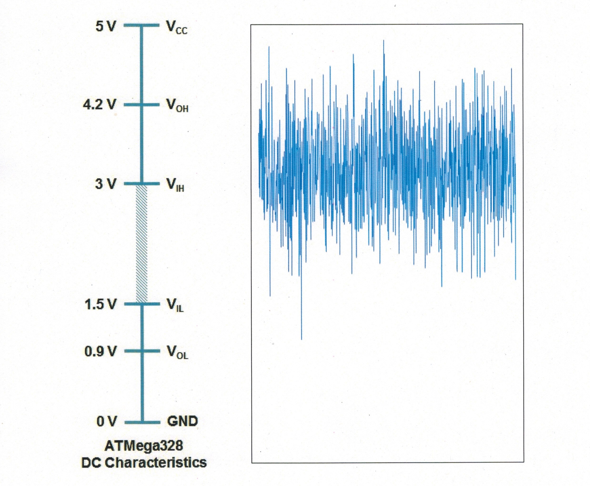
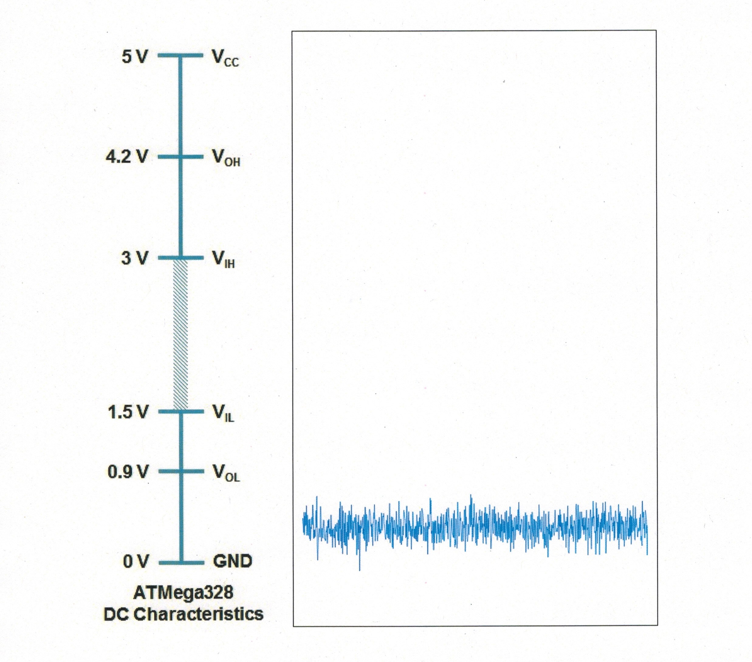

Suppose we have a mechanical switch driving a logic input. The switch is in the “open” position. The signal that arrives at the logic card input has 4 volts of EMI impressed upon it. How does that affect what the logic card “sees” at the input? In this example the logic card would be completely incapable of detecting a VALID high or low signal from the switch.
![]()
2017-10-10