


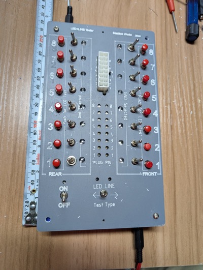
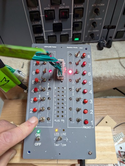
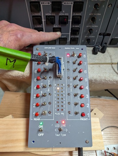
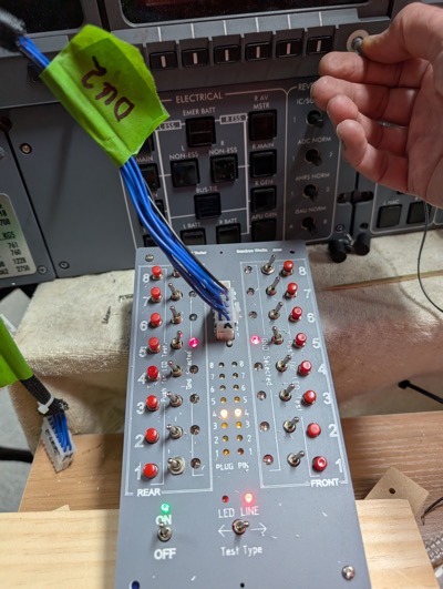
Hi Folks, I am in the middle of re-wiring all my panels using the Jet45 AAC as a guide to panel and loom wiring. I was testing the completed wiring looms using a multimeter, which was a bit tedious. To improve the flow I built a box with which I can plug the end of the loom into, and easily test either the LED in the panel, or the switch itself on the panel. It tests the line continuity and shows which PIN on the plug it is connected to. It looks like this: It is designed to fit a UB2 Jiffy Box (187x112x63mm). I have 3D printed my own 30mm tall jiffy box as its more convenient, Power by 3-5V DC. I have put a 2.1mm panel mount socket on both the top and bottom walls on the jiffy box so I can plug power in either end depending on where I want the power plug & cable to be. I also have found it useful to be able to plug a clip/probe lead into the other for further checking. It tests the Val-U-Look plugs up to 2x8 (16 position) which is the largest plug we use. It could test any style plug up to 2x8 with a suitable adaptor. All switches and indicators are arranged in the same pin order as the plug. Re pin numbering I use the terms ‘front’(F) and ‘rear’ (R), ‘front’ being the side with the clip, looking at the pin insertion end. Each side has pins ‘1’ to’8’ from bottom up. This helps resolve the problem of identifying pins on different sized connectors and different orientations in the Jet45 AAC At the bottom is the ON/OFF toggle and the LED/LINE test selector toggle. Two vertical columns of 8 Toggle switches are for selecting which pins are GND/Common pins. Inside of each toggle is a red LED to indicate which pin/s have been switched to be GND. In the middle at the top is the connector. Any Val-U-Lok plug from 2x1 up to 2x8 can be connected – clip side to the right. Below that are 2 columns of 8 LED line indicators. These indicate which pin a switch is connected to. With the ‘Test Type’ toggle to “Line” and your loom plugged in, activate any switch on that loom and the LED for the pin it is connected to will illuminate. If nothing illuminates, then there is a problem with either the switch or the loom. Push buttons on outer left and right are for testing an LED loom. With the ‘Test Type’ toggle to “LED”, push to activate the LED that is attached to that pin. If nothing illuminates then there is a problem with either the LED or the loom. A couple of photos of in use. Testing the Electrical Panel lower 2x5 LED loom with F6 and R6 selected as GND (as per loom). Push button R1, APU GEN lower LED illuminates. This is correct. Testing the Electrical Panel 2x8 Switch loom. F8 selected as GND … Press Bus Tie button and pin R7 illuminates – correct. Testing the DU2 encoder. F5 andR5 selected as GND. Rotating the encoder activates the two associated pins causing them to flash as the encoder is rotated. Pins F3 and R3 connect. V If anyone is interested in one of these Line/LED Test boxes please let me know. If there is enough interest I will order a run of PCB’s. The above example is a prototype, and its PCB is part Printed Circuit and part connecting wires to fix errors as necessary. I am happy to provide a kit with as much (or little) components as needed for you to assemble. I am not volunteering to assemble these as my soldering skills are not what they used to be. Please be aware that there are about 260 solder points per board. Hi Folks, I am in the middle of re-wiring all my panels using the Jet45 AAC as a guide to panel and loom wiring. I was testing the completed wiring looms using a multimeter, which was a bit tedious. To improve the flow I built a box with which I can plug the end of the loom into, and easily test either the LED in the panel, or the switch itself on the panel. It tests the line continuity and shows which PIN on the plug it is connected to. It looks like this: It is designed to fit a UB2 Jiffy Box (187x112x63mm). I have 3D printed my own 30mm tall jiffy box as its more convenient, Power by 3-5V DC. I have put a 2.1mm panel mount socket on both the top and bottom walls on the jiffy box so I can plug power in either end depending on where I want the power plug & cable to be. I also have found it useful to be able to plug a clip/probe lead into the other for further checking. It tests the Val-U-Look plugs up to 2x8 (16 position) which is the largest plug we use. It could test any style plug up to 2x8 with a suitable adaptor. All switches and indicators are arranged in the same pin order as the plug. Re pin numbering I use the terms ‘front’(F) and ‘rear’ (R), ‘front’ being the side with the clip, looking at the pin insertion end. Each side has pins ‘1’ to’8’ from bottom up. This helps resolve the problem of identifying pins on different sized connectors and different orientations in the Jet45 AAC At the bottom is the ON/OFF toggle and the LED/LINE test selector toggle. Two vertical columns of 8 Toggle switches are for selecting which pins are GND/Common pins. Inside of each toggle is a red LED to indicate which pin/s have been switched to be GND. In the middle at the top is the connector. Any Val-U-Lok plug from 2x1 up to 2x8 can be connected – clip side to the right. Below that are 2 columns of 8 LED line indicators. These indicate which pin a switch is connected to. With the ‘Test Type’ toggle to “Line” and your loom plugged in, activate any switch on that loom and the LED for the pin it is connected to will illuminate. If nothing illuminates, then there is a problem with either the switch or the loom. Push buttons on outer left and right are for testing an LED loom. With the ‘Test Type’ toggle to “LED”, push to activate the LED that is attached to that pin. If nothing illuminates then there is a problem with either the LED or the loom. A couple of photos of in use. Testing the Electrical Panel lower 2x5 LED loom with F6 and R6 selected as GND (as per loom). Push button R1, APU GEN lower LED illuminates. This is correct. Testing the Electrical Panel 2x8 Switch loom. F8 selected as GND … Press Bus Tie button and pin R7 illuminates – correct. Testing the DU2 encoder. F5 andR5 selected as GND. Rotating the encoder activates the two associated pins causing them to flash as the encoder is rotated. Pins F3 and R3 connect. V If anyone is interested in one of these Line/LED Test boxes please let me know. If there is enough interest I will order a run of PCB’s. The above example is a prototype, and its PCB is part Printed Circuit and part connecting wires to fix errors as necessary. I am happy to provide a kit with as much (or little) components as needed for you to assemble. I am not volunteering to assemble these as my soldering skills are not what they used to be. Please be aware that there are about 260 solder points per board. Hey Will, This is a very neat tool, very intuitive too. I have my sim completely wired up and tested, otherwise I would be interested in one of these tools. Looks like it will save a ton of time during the confirmation process. Great work Will! Hey Will, This is a very neat tool, very intuitive too. I have my sim completely wired up and tested, otherwise I would be interested in one of these tools. Looks like it will save a ton of time during the confirmation process. Great work Will!Line/LED Tester
![]()
![]()
2017-10-10