


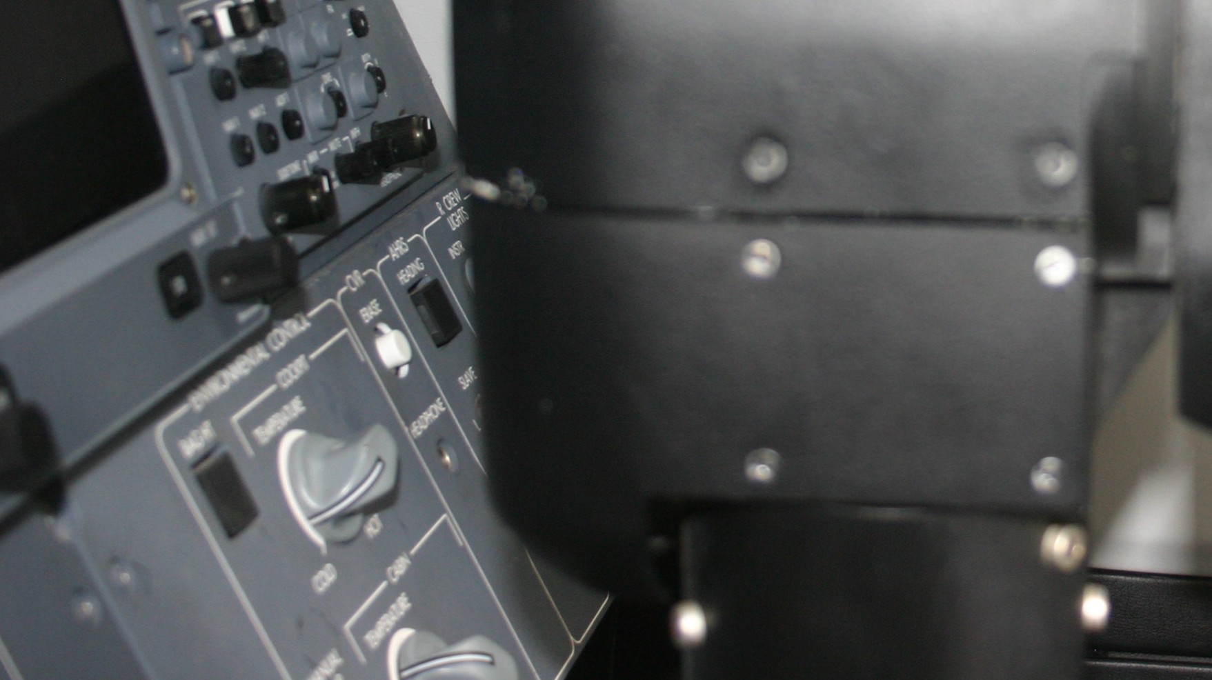
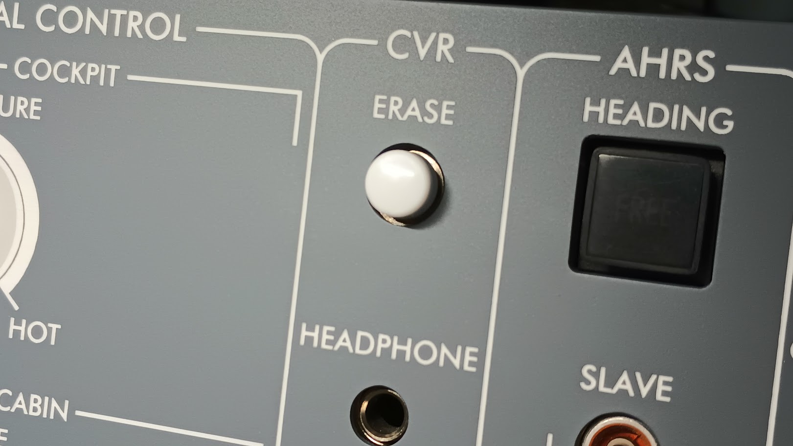
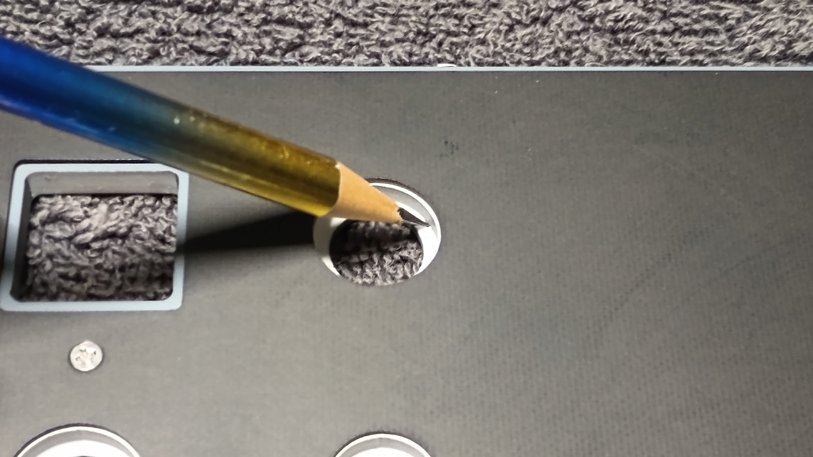
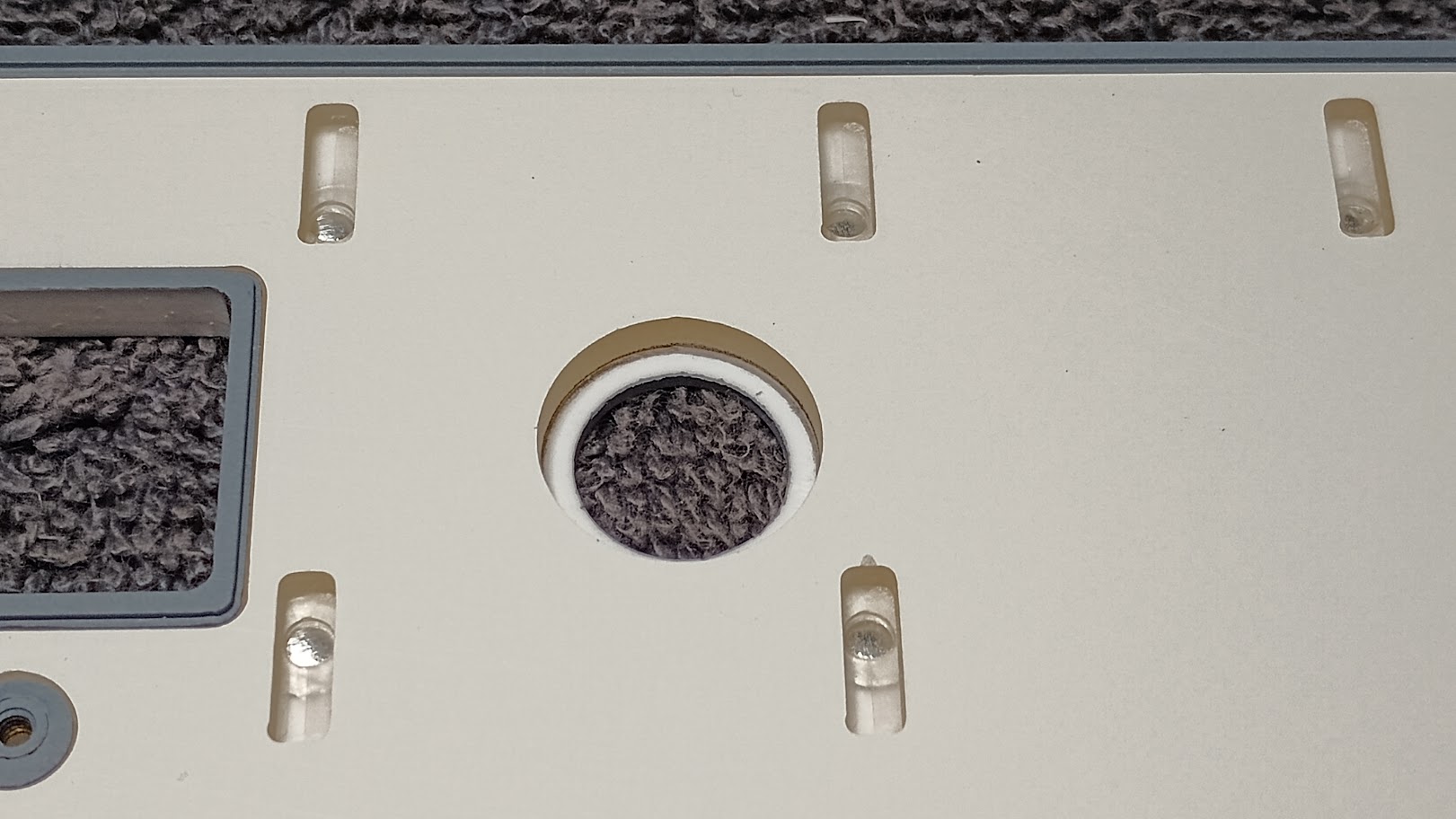
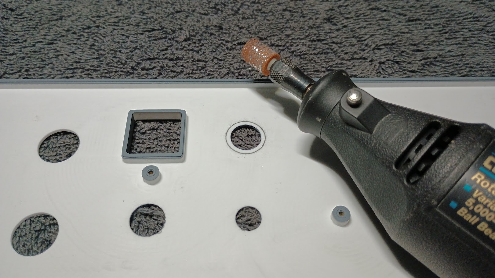
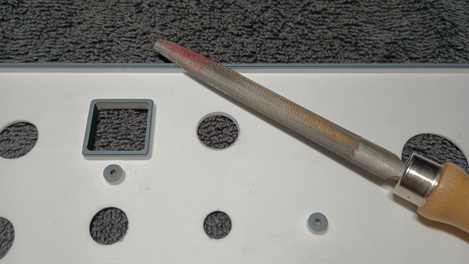
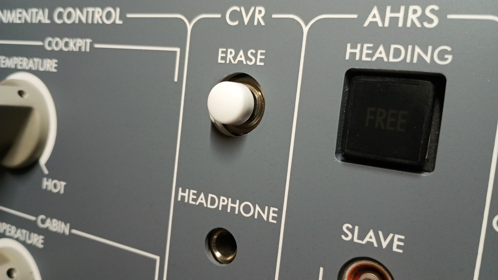
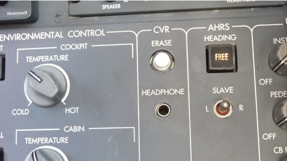
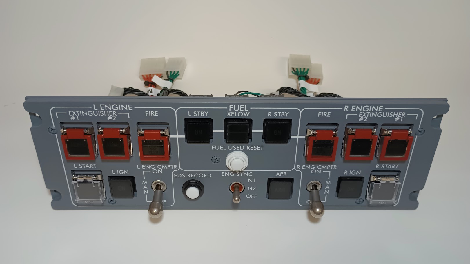
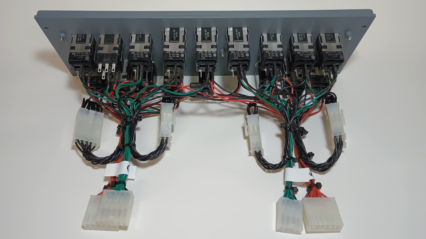
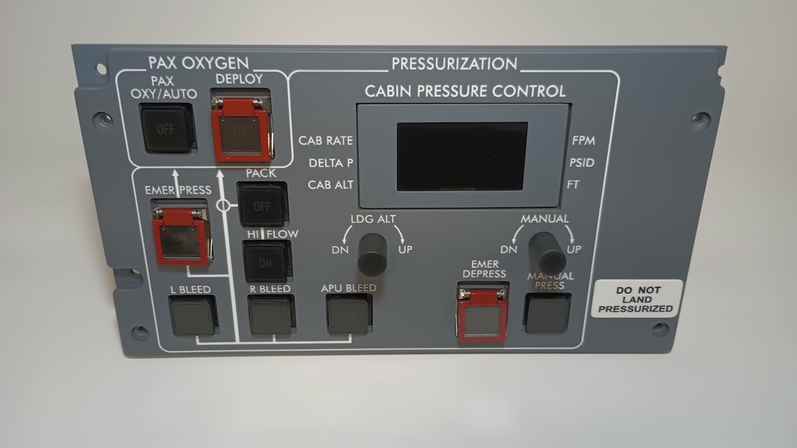
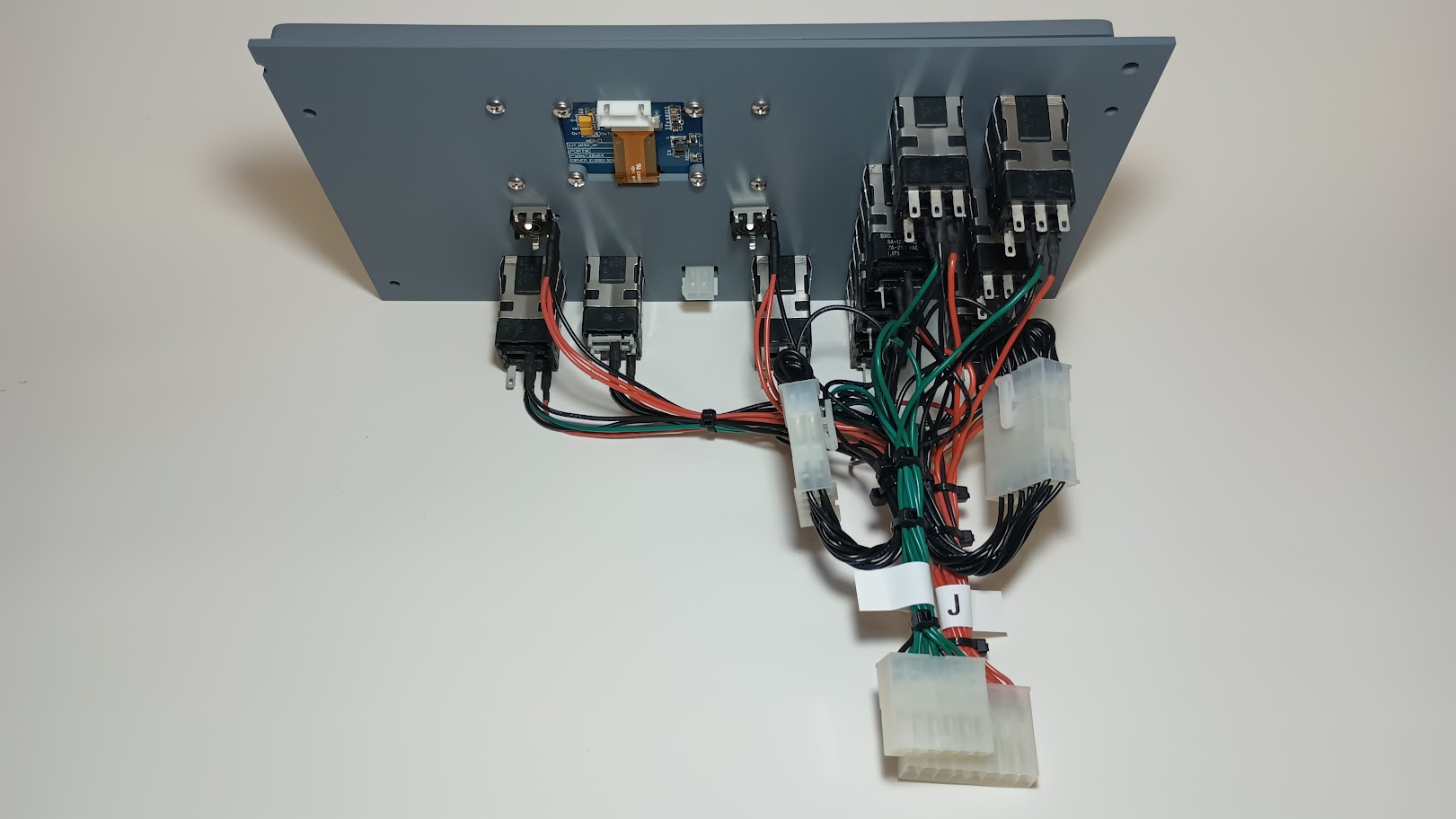
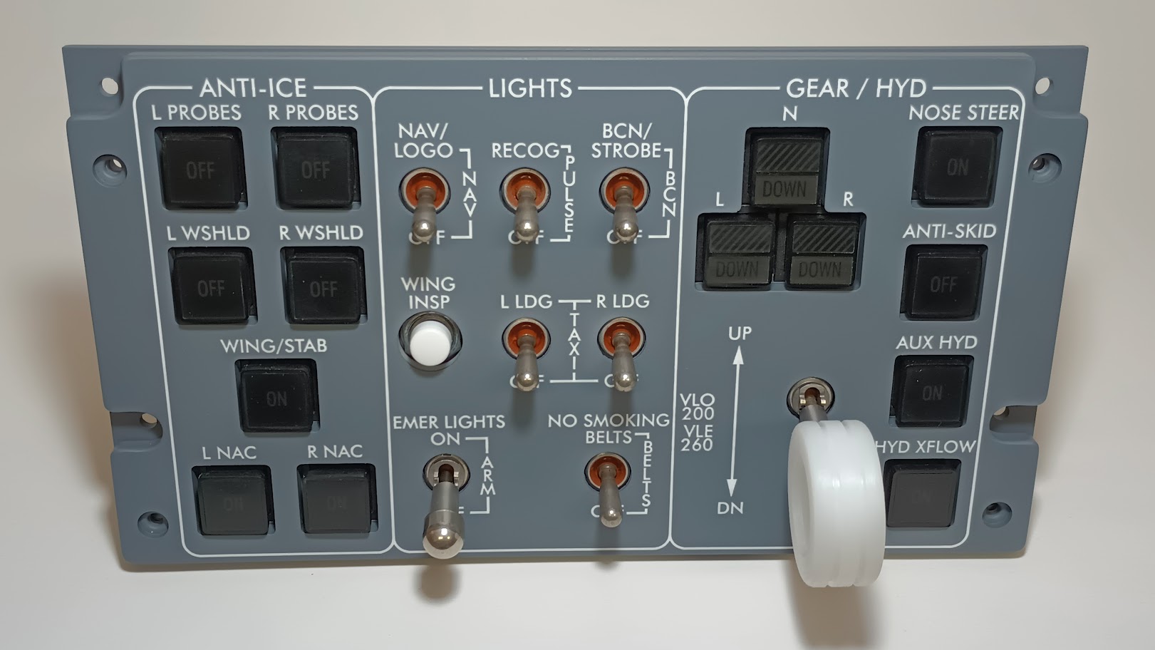
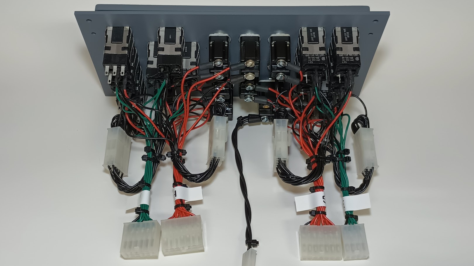
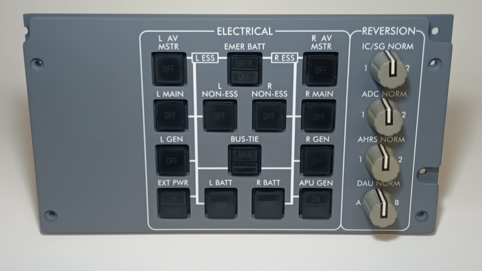
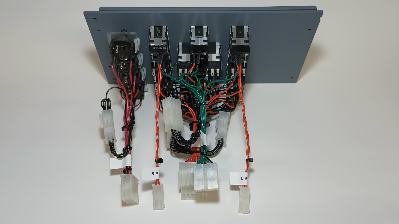
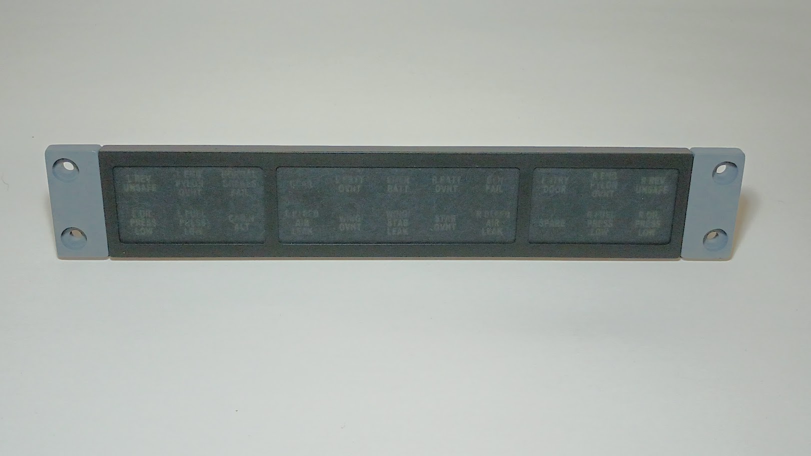
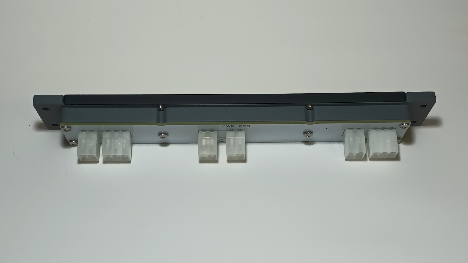
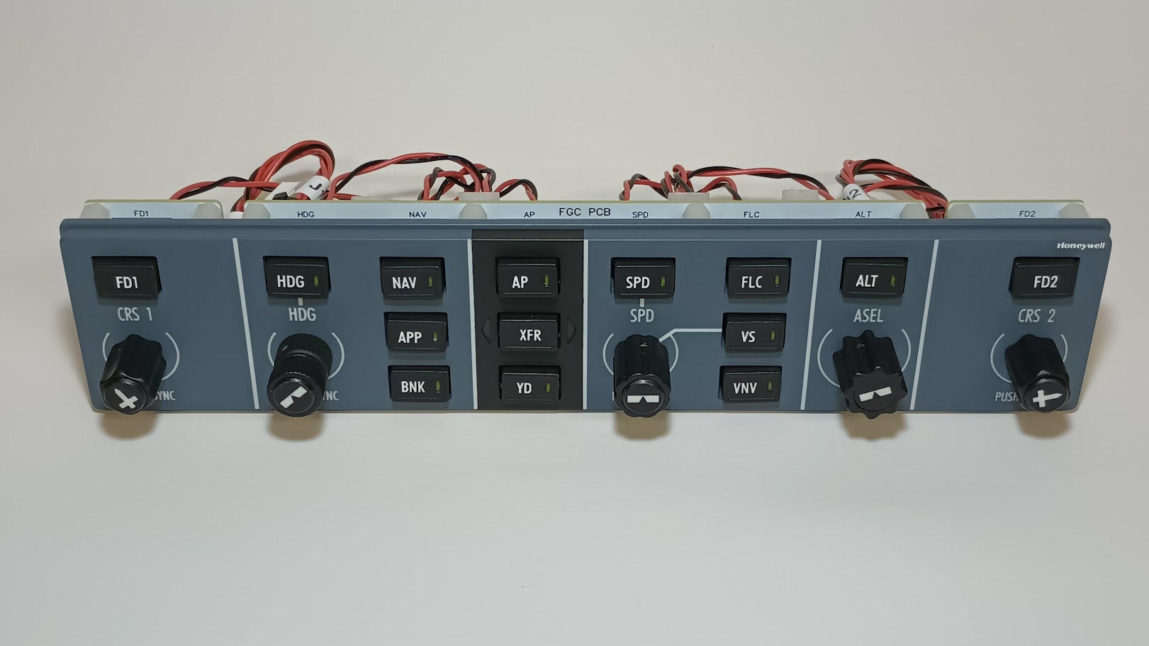
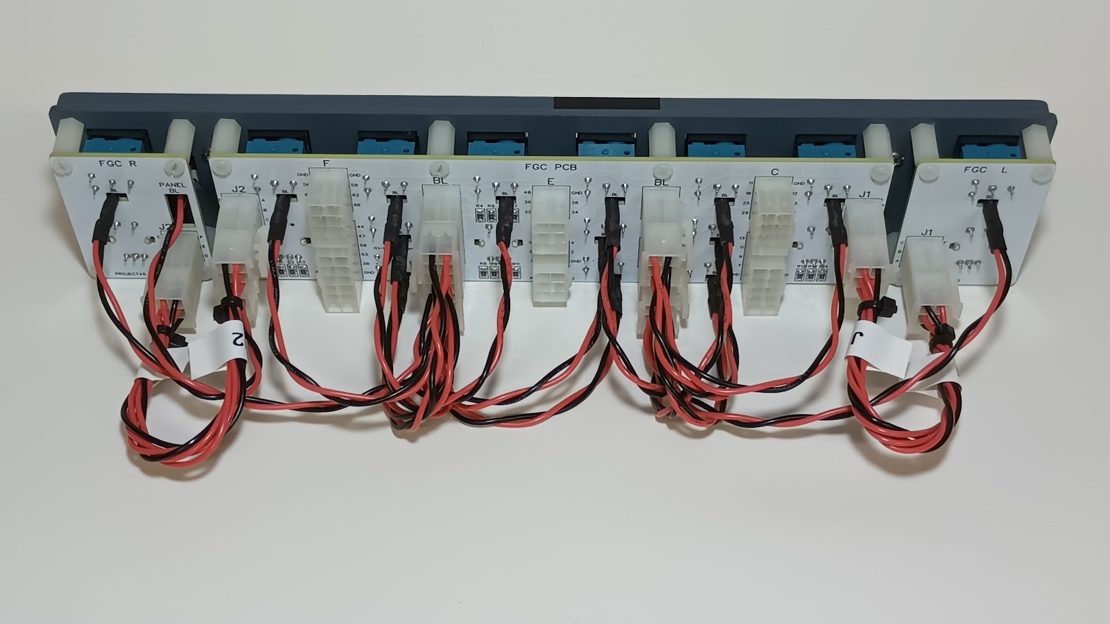
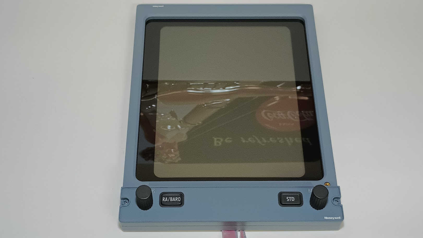
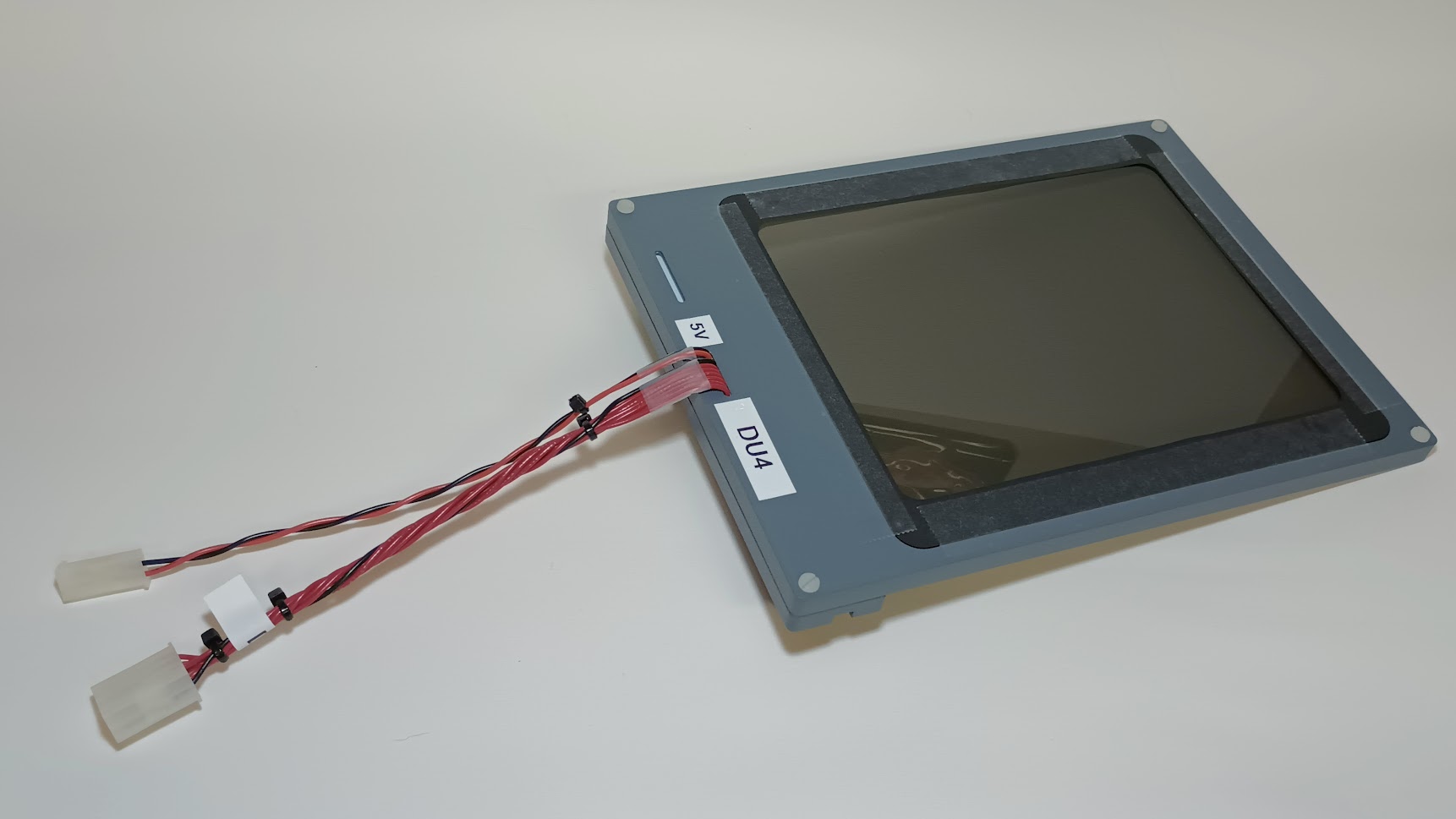
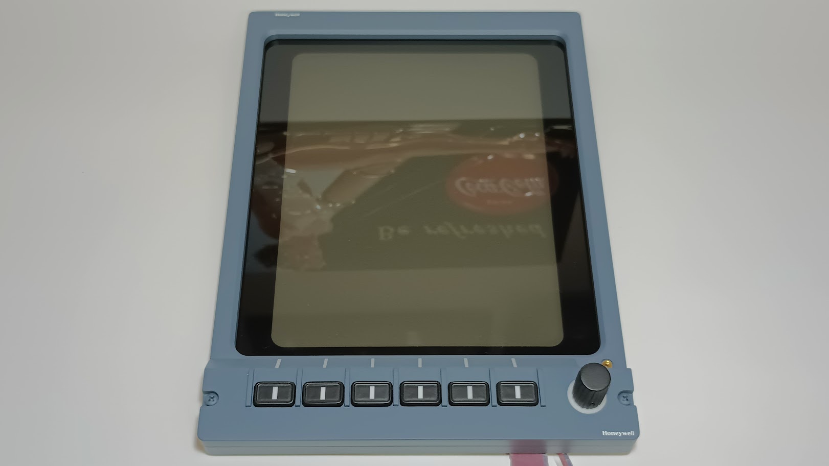
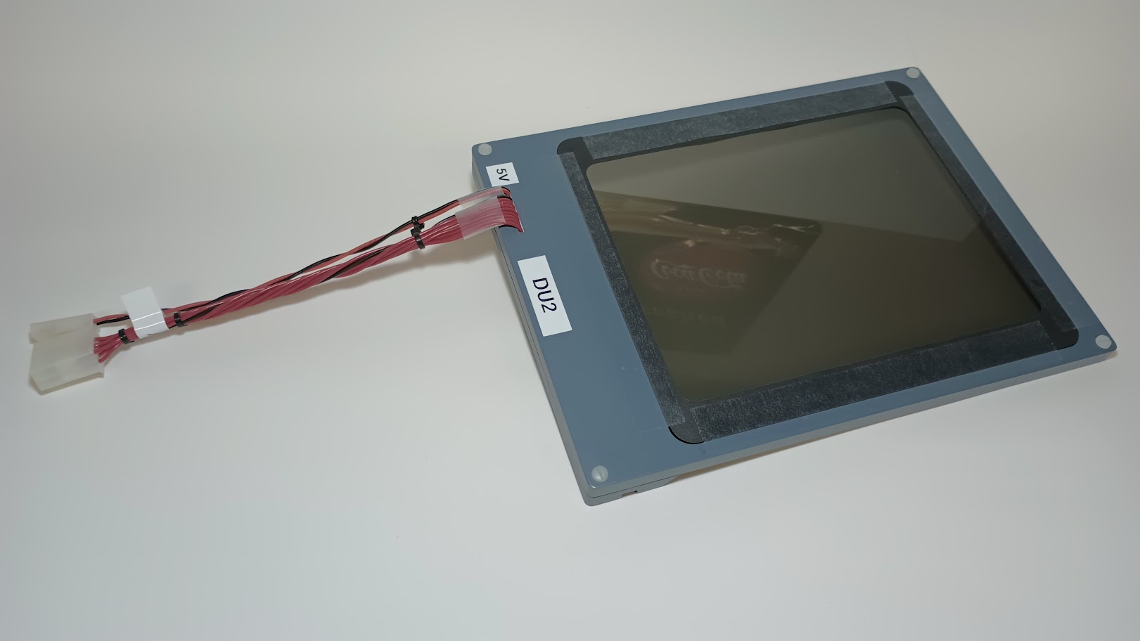
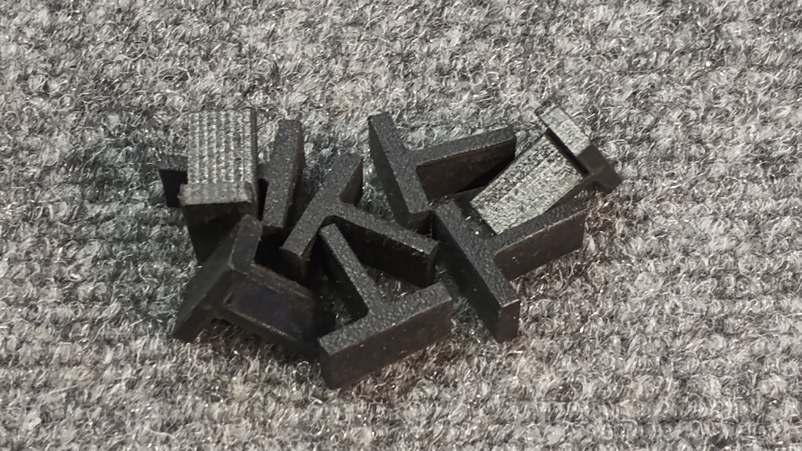
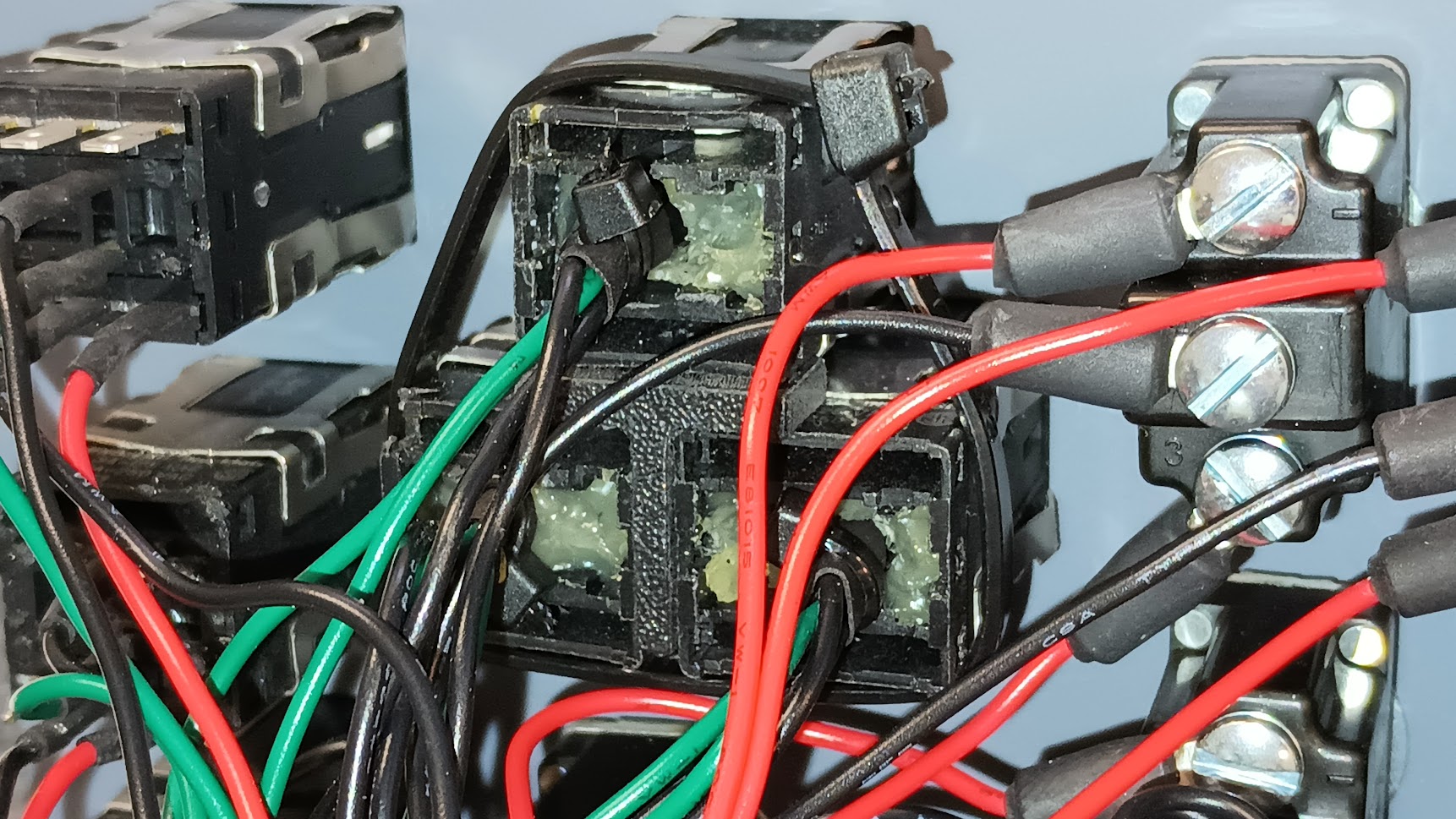
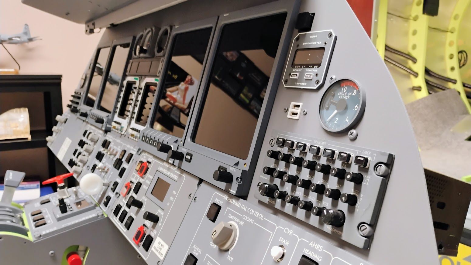
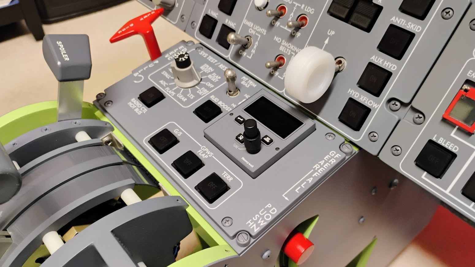
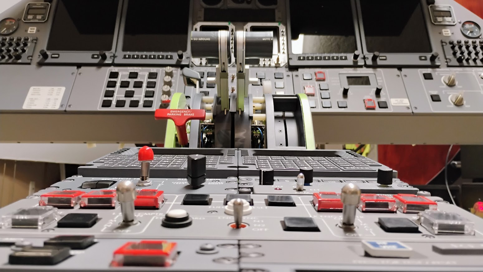
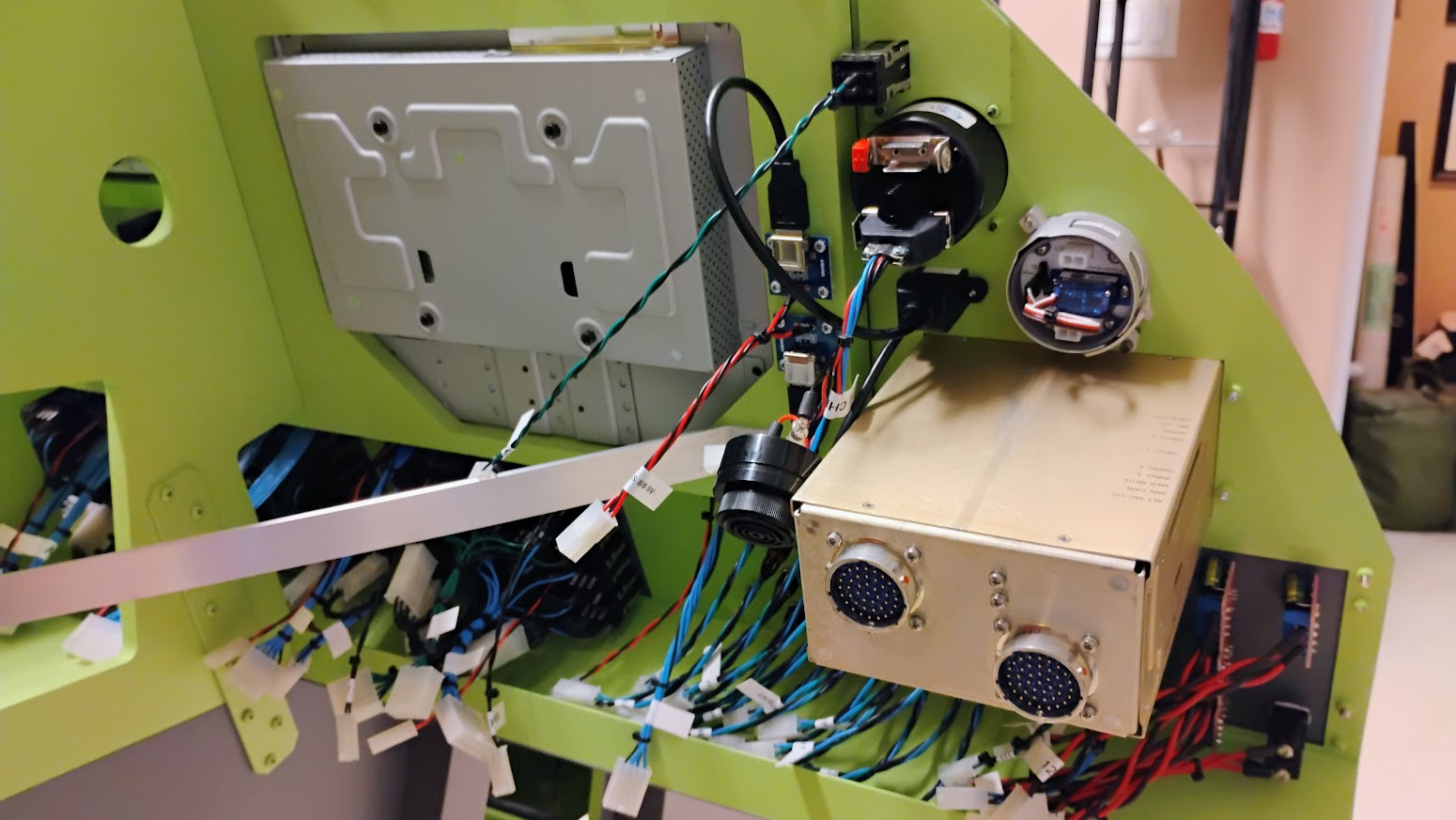
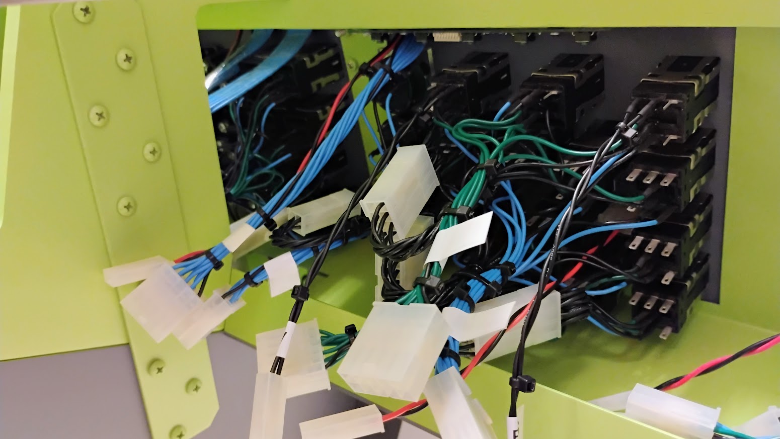
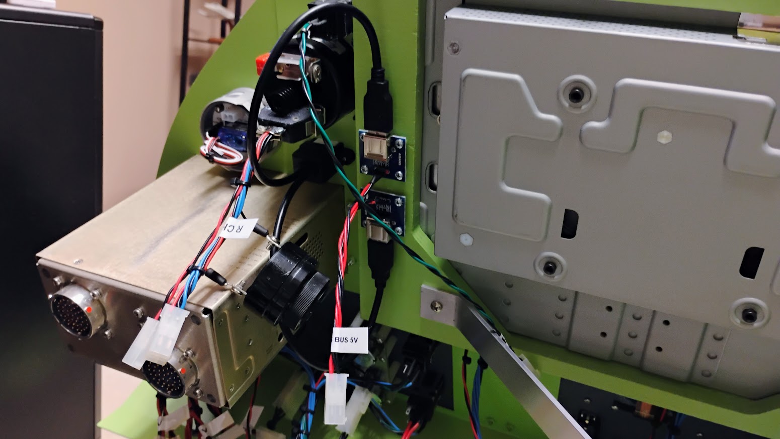
I have the next batch of panels with wiring just about completed but before I post them up, I wanted to share with you a small oversight and fix. The CVR ERASE button hole on the Environmental panel needs to be opened up slightly. I have this corrected in my drawings and G-code but wanted to give the guys who have this panel the opportunity to correct it if they want to. It's an easy fix but I still found it a little nerve wracking because it would also be pretty easy to screw the face of the panel up. So if you are not comfortable with your fine motor skills, leave this fix alone! The CVR ERASE button hole is much wider than I had it drawn out to be. I was able to confirm with a couple photos that it was in fact open, see photo of real Lear45 below. This was my Environmental panel before I made the correction. The easiest way to go about this fix is to use a Drimel tool, but you need to have a perfect circle as a guide. The internal light plate acts as a template for your circle. Here the Light Clad has been removed and the pencil line can be seen. And here the internal Light Plate has been removed. The easiest way to remove the majority of the material is with the Drimel tool. CAUTION: If you have little to no experience with Drimel tools and modifying plastics like this, please leave this alone! If need be, send the panel back to me and I will open it up for you. The final bits of removal are done with a round file. What you are left with is a hole closer to scale and looking the part! Here is the before photo again so you can see the difference clearly. And one more photo. (Actually this is the real Lear45) Believe it or not, this is the only error I have come across so far with all the panels that needed to be corrected. Although a minor error and easy to fix. In the next few days I will get the next batch of finished and wired panels posted up for reference! I have the next batch of panels with wiring just about completed but before I post them up, I wanted to share with you a small oversight and fix. The CVR ERASE button hole on the Environmental panel needs to be opened up slightly. I have this corrected in my drawings and G-code but wanted to give the guys who have this panel the opportunity to correct it if they want to. It's an easy fix but I still found it a little nerve wracking because it would also be pretty easy to screw the face of the panel up. So if you are not comfortable with your fine motor skills, leave this fix alone! The CVR ERASE button hole is much wider than I had it drawn out to be. I was able to confirm with a couple photos that it was in fact open, see photo of real Lear45 below. This was my Environmental panel before I made the correction. The easiest way to go about this fix is to use a Drimel tool, but you need to have a perfect circle as a guide. The internal light plate acts as a template for your circle. Here the Light Clad has been removed and the pencil line can be seen. And here the internal Light Plate has been removed. The easiest way to remove the majority of the material is with the Drimel tool. CAUTION: If you have little to no experience with Drimel tools and modifying plastics like this, please leave this alone! If need be, send the panel back to me and I will open it up for you. The final bits of removal are done with a round file. What you are left with is a hole closer to scale and looking the part! Here is the before photo again so you can see the difference clearly. And one more photo. (Actually this is the real Lear45) Believe it or not, this is the only error I have come across so far with all the panels that needed to be corrected. Although a minor error and easy to fix. In the next few days I will get the next batch of finished and wired panels posted up for reference! Hey guys, I got the next set of panels wired up and completed. What a job it was and still is! While wiring all these panels, I have been taking care of other little details, buttons, bezels, risers, knobs, etc... which adds to the process. I wanted to post up all the panels, front and back for illustration purposes. How often do we get to see the inner workings of the back side of the panels? (If you are using Firefox or an equivalent browser, you can right click on the images and open them up in a new tab to enlarge) Here is the next batch in no particular order. Engine Panel: Pressurization Panel: Gear Hyd Panel: Electrical Panel: Crew Warning Panel: FGC Panel: Display Units 1&4: Display Units 2&3: I have one more batch of panels that I will be adding to this list but it is going to be a little while because I am in the process of creating a v2.0 of them. Those panels are the RMUs, EFIS Panels and the Airshow Panel. Additionally, I will be working on a all new CDU replica and later on down the road we will be releasing a version of the Audio Control Panels. Hey guys, I got the next set of panels wired up and completed. What a job it was and still is! While wiring all these panels, I have been taking care of other little details, buttons, bezels, risers, knobs, etc... which adds to the process. I wanted to post up all the panels, front and back for illustration purposes. How often do we get to see the inner workings of the back side of the panels? (If you are using Firefox or an equivalent browser, you can right click on the images and open them up in a new tab to enlarge) Here is the next batch in no particular order. Engine Panel: Pressurization Panel: Gear Hyd Panel: Electrical Panel: Crew Warning Panel: FGC Panel: Display Units 1&4: Display Units 2&3: I have one more batch of panels that I will be adding to this list but it is going to be a little while because I am in the process of creating a v2.0 of them. Those panels are the RMUs, EFIS Panels and the Airshow Panel. Additionally, I will be working on a all new CDU replica and later on down the road we will be releasing a version of the Audio Control Panels. Terry Collins identified an issue that you may also have noticed and that is the way the three pack landing gear indicators might be a little loose. The reason they are not as secure as all the other AML switches is because there is not adequate support on all four sides of each of the three AML bodies. Terry came up with a simple and easy fix by creating a "T" spacer that slips in between the three AML bodies and then zip ties together. I never really noticed the issue but after taking a closer look, I can see where they can possibly slip and get misaligned if someone attempts to press them, not knowing they are only indicators. I took Terry's idea and created a dxf file and cut several "T" pieces that I call "Gear Tri Pack Locks". They are made of a Poly plastic and fit snug in between the three AMLs. Zip tie the AMLs together and you will never have to worry about your landing gear indicators slipping out of alignment! It's hard to see the "T" piece in place but it's there! (It only takes one.) I have several of these made up and if anyone needs one, just send me an email and I will get one out to you the next time I am sending a package your way. Or I can sent you the dxf/G code file if you want to make one. Thanks to Terry for identifying the issue and coming up with a solid solution! Terry Collins identified an issue that you may also have noticed and that is the way the three pack landing gear indicators might be a little loose. The reason they are not as secure as all the other AML switches is because there is not adequate support on all four sides of each of the three AML bodies. Terry came up with a simple and easy fix by creating a "T" spacer that slips in between the three AML bodies and then zip ties together. I never really noticed the issue but after taking a closer look, I can see where they can possibly slip and get misaligned if someone attempts to press them, not knowing they are only indicators. I took Terry's idea and created a dxf file and cut several "T" pieces that I call "Gear Tri Pack Locks". They are made of a Poly plastic and fit snug in between the three AMLs. Zip tie the AMLs together and you will never have to worry about your landing gear indicators slipping out of alignment! It's hard to see the "T" piece in place but it's there! (It only takes one.) I have several of these made up and if anyone needs one, just send me an email and I will get one out to you the next time I am sending a package your way. Or I can sent you the dxf/G code file if you want to make one. Thanks to Terry for identifying the issue and coming up with a solid solution! Hey Ron, this is a great thread for those (like me) currently in the wiring phase. The wiring I see here is impeccable! Hey Ron, this is a great thread for those (like me) currently in the wiring phase. The wiring I see here is impeccable! Hey guys, I'm working to update several threads with the most recent work I have been doing lately. Just this week I have finished the furniture pieces with paint and have the majority of the panels mounted to them. Here are a couple highlight photos of all the panels together mounted on the new furniture pieces. Making some serious progress and now we can clearly see the light at the end of the tunnel! One area I have been really looking forward to finishing is the "Airplane" panel found behind the Weight Chart panel. Here the Weight Chart panel is removed exposing the "Airplane" panel. Pretty cool! This panel obviously does not exist in the real Lear45, however, it's a convenient extension of the reset switches for the majority of the Arduinos within the simulator, right here at your fingertips......if needed. The backside of the "Airplane" panel with 80 wires coming out of it ready to be connected to all the Arduino modules. Another neat option is the dual USB sockets mounted on the left and right MIP under the Davtron clocks. Our friend Dugald down under flew a Lear45 with these additional dual USB sockets installed. These days, USB sockets are a MUST anywhere and everywhere and a lot of older aircrafts are being retrofitted with USB sockets. On the rear of the MIP, I have the two USB cables plugged into a couple USB sockets. From there, the 5v power lines run to the L NON ESS BUS via a 12v to 5v converter. (The FO side runs to the R NON ESS BUS) As I covered in an earlier post, all the panels have been wired and are ready for their wiring harnesses. Here are a couple photos of the back side of all the panels. CPT rear side. FO rear side. Center rear side. Just a few more panels to go! Next up will be the final essential panels, the v2.0 EFIS panels, the v2.0 RMUs and the v2.0 WX Radar panel. Here's one final overall look at where I am at with the panel development. Later I will take on the ACP panels, the curved TQ panel and the Circuit breaker panels. I will have more updates shortly once I start the next production run of the remaining essential panels. Hey guys, I'm working to update several threads with the most recent work I have been doing lately. Just this week I have finished the furniture pieces with paint and have the majority of the panels mounted to them. Here are a couple highlight photos of all the panels together mounted on the new furniture pieces. Making some serious progress and now we can clearly see the light at the end of the tunnel! One area I have been really looking forward to finishing is the "Airplane" panel found behind the Weight Chart panel. Here the Weight Chart panel is removed exposing the "Airplane" panel. Pretty cool! This panel obviously does not exist in the real Lear45, however, it's a convenient extension of the reset switches for the majority of the Arduinos within the simulator, right here at your fingertips......if needed. The backside of the "Airplane" panel with 80 wires coming out of it ready to be connected to all the Arduino modules. Another neat option is the dual USB sockets mounted on the left and right MIP under the Davtron clocks. Our friend Dugald down under flew a Lear45 with these additional dual USB sockets installed. These days, USB sockets are a MUST anywhere and everywhere and a lot of older aircrafts are being retrofitted with USB sockets. On the rear of the MIP, I have the two USB cables plugged into a couple USB sockets. From there, the 5v power lines run to the L NON ESS BUS via a 12v to 5v converter. (The FO side runs to the R NON ESS BUS) As I covered in an earlier post, all the panels have been wired and are ready for their wiring harnesses. Here are a couple photos of the back side of all the panels. CPT rear side. FO rear side. Center rear side. Just a few more panels to go! Next up will be the final essential panels, the v2.0 EFIS panels, the v2.0 RMUs and the v2.0 WX Radar panel. Here's one final overall look at where I am at with the panel development. Later I will take on the ACP panels, the curved TQ panel and the Circuit breaker panels. I will have more updates shortly once I start the next production run of the remaining essential panels. Looking very neat. I mounted too few connectors, so when replacing some LED's which broke, need to dismount a lot now.. Looking very neat. I mounted too few connectors, so when replacing some LED's which broke, need to dismount a lot now.. Thanks Roel! It has been a process to get to this point with a lot of ups and downs with many lessons learned along the way. This is my second build of the Lear45 and there were many things we did in the first version that were good ideas but many more that were bad. And many other things forgotten or left out. On top of that, most of us started off with skill level negative zero as amateurs when it comes to the crafts involved with this hobby and literally learning on the fly when it comes to building techniques. So although it has taken some time to get to this point, it's really starting to come together. One thing that none of us have time for is chasing down gremlins. This is the biggest reason why I have taken the extra time to insure everything is squared away with solder joints, shrink wrap, zip ties and proper labeling. Nothing is fool proof but if we can eliminate 99% of the gremlins, we are doing great! Thanks Roel! It has been a process to get to this point with a lot of ups and downs with many lessons learned along the way. This is my second build of the Lear45 and there were many things we did in the first version that were good ideas but many more that were bad. And many other things forgotten or left out. On top of that, most of us started off with skill level negative zero as amateurs when it comes to the crafts involved with this hobby and literally learning on the fly when it comes to building techniques. So although it has taken some time to get to this point, it's really starting to come together. One thing that none of us have time for is chasing down gremlins. This is the biggest reason why I have taken the extra time to insure everything is squared away with solder joints, shrink wrap, zip ties and proper labeling. Nothing is fool proof but if we can eliminate 99% of the gremlins, we are doing great!V2.0 Panel Progress by Project45
![]()
![]()
![]()
![]()
![]()


![]()
I know what I am going to do when one day (which sure will come) rebuilding my sim, and this is being able to service all instruments from within the cockpit!
I know what I am going to do when one day (which sure will come) rebuilding my sim, and this is being able to service all instruments from within the cockpit!![]()
Forum NavigationV2.0 Panel Progress by Project45
![]() #31 · November 1, 2022, 3:16 pm
#31 · November 1, 2022, 3:16 pm![]() #32 · November 8, 2022, 7:47 pm
#32 · November 8, 2022, 7:47 pm![]() #33 · November 9, 2022, 9:33 pm
#33 · November 9, 2022, 9:33 pm![]() #34 · November 18, 2022, 8:20 am
#34 · November 18, 2022, 8:20 am![]() #35 · January 27, 2025, 10:18 pmMark Speechley has reacted to this post.Mark Speechley
#35 · January 27, 2025, 10:18 pmMark Speechley has reacted to this post.Mark Speechley![]() #36 · January 28, 2025, 4:25 amRon Rollo has reacted to this post.Ron Rollo
#36 · January 28, 2025, 4:25 amRon Rollo has reacted to this post.Ron Rollo![]() #37 · January 28, 2025, 9:54 amMark Speechley has reacted to this post.Mark Speechley
#37 · January 28, 2025, 9:54 amMark Speechley has reacted to this post.Mark Speechley
2017-10-10