


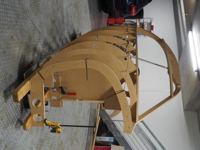
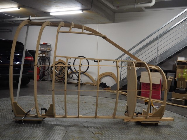
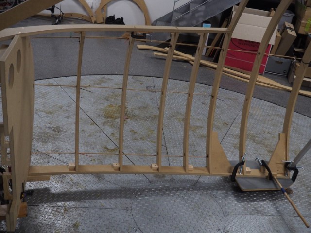
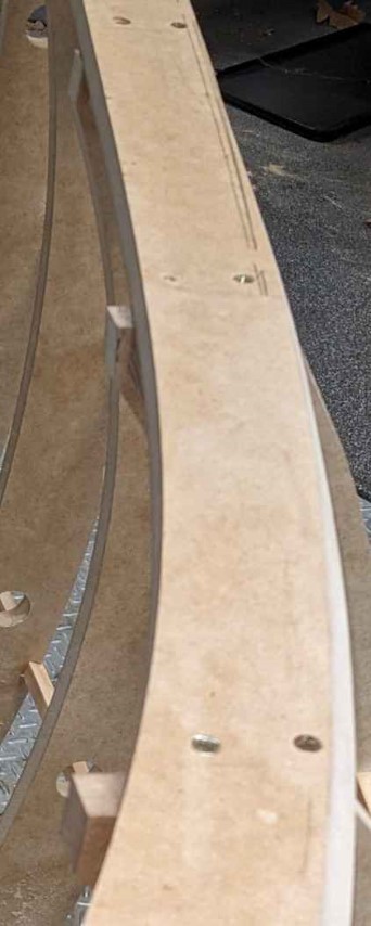
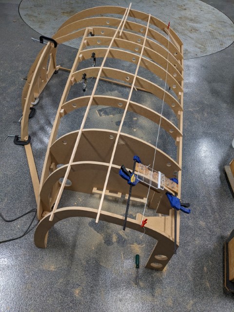
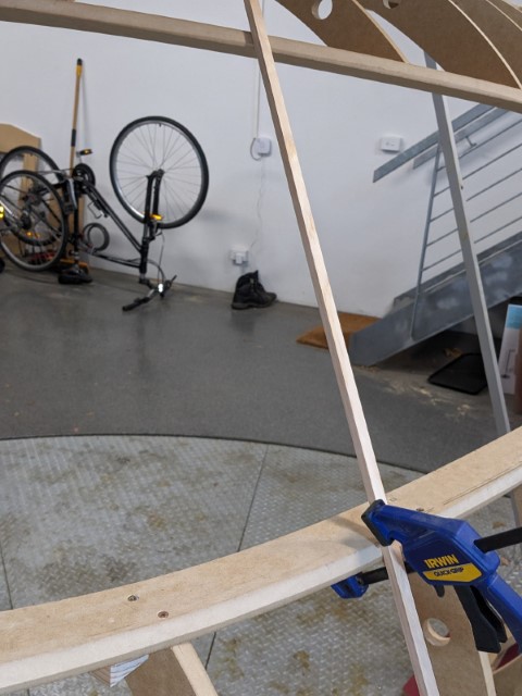
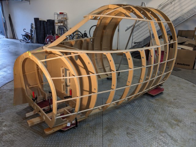
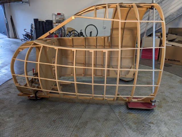
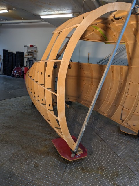
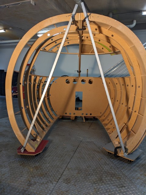
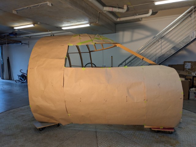
For a while I have been working on creating a 3D digitised version of Rons Shell with the aim of having a set of CNC ready files for builders to use. Well, its almost done, Phew!! It has been a bigger task than I expected, and I learnt a lot on the way (thank god for youtube tutorials and Ron's patience!). I created the model in Autodesk’s Fusion 360 and it has pretty well enabled me to do most that I required. It’s mainly been a matter of me learning a better way to do it.. I thought its now time to say, by george I think I’ve (nearly) done it! All that’s left to design is the interior trim panels, and build a full shell. In an effort to make it compatible, I also digitised the platform, raised deck, and MIP furniture (Centre Console, TQ Stand, and MIP tower) – all to Rons version 2 standards. The MIP and glare shield panel already exist in digital format and I used these in the design. Everything looks like it fits, the main concern was getting a good fit around the MIP. This image is a cross section parallel to and through the main surface of the MIP. You can see there is enough and not too much clearance at the sides. One major change is the length. I have added a 370mm extension to the rear by adding F10, which is a duplicate of F9 without the holes. I chose 370mm as this made the spine and base-rail about as long as you can get , with a little wriggle room, on a 1.2x2.4 sheet. I have added this to create a peripheral vision block as when flying Mark S’s sim with an open back F9 I experienced peripheral glimpses of the real world. This unsettled the full immersion experience. So I intend to build open back extended version, not Rons original ‘Classic’. I could build the Classic with the rear cockpit panels installed to do the same thing, but I want an open back to ease entry and exit contortions for people and enable good viewing from behind the sim. If you want to build the Classic you cut the spine and base-rail at F9 position and fix F10 (with no holes) in place at the F9 station. Note: F1 and F10 fit to the end of the spine and base-rail, whereas F9 and all other frames sit on top of the base-rail and butt up to the spine. The cockpit rear wall panels either side of the cockpit doorway are designed to fit to the inside of F9 or F10. They can be added at any time. The raised floor panels are stepped at the back to accommodate these panels. Using this system you can build as much cabin length as you want, just add straight pieces of wood to the spine and base-rail and cut as many F9’s as you want. For a cleaner finish, install an F10 as the final frame. One general issue raised is the amount of support under the raised floor, ie the wooden runners supporting the floor sheets. If you think you might have some XXXL+ people climbing in it would be wise to add more underfloor support pieces. Any cnc shop would be able to pick the parts out and replicate.. There is 2 different lengths, one for under the main pilot seats, and one for the 370mm extension. Another way to increase the support under the raised floor is to not use the CNC’d pieces but use 1 ¼” timber. The design height of these supports are 32.8mm, whereas 1 ¼” = 31.75mm, 1mm shorter. Close enough that it wont matter. Then you can easily install as much support as you want. As an added bonus I created a flat template for cutting the windshield: …and for those who may dislike fibreglass but believe an English Wheel is a real mans tool, I also have flat pattern for skinning the shell with sheet material in 4 or more pieces: I hope to place the DXf files (2D) on the forum when finalised. They will be set to use 1.2m x 2.4m (4ft x 8ft) sheet stock. I have designed for 18mm (3/4”) sheet which is what I will be building but any thickness can be used. If you wanted to use different size stock I suggest you make the spine and base-rail from 18mm stock, for everything else the thickness doesn’t matter as the shape is what’s important. Having said that, I think even if you made everything from 12.6mm (1/2") you probably wouldn't notice the difference, you potentially would lose 6mm (1/4') from the finished height and 12mm (1/2') from width. Now, off to get a set cut ... and a little teaser... As part of my prototyping I made a 10% scale model. More on that soon... For a while I have been working on creating a 3D digitised version of Rons Shell with the aim of having a set of CNC ready files for builders to use. Well, its almost done, Phew!! It has been a bigger task than I expected, and I learnt a lot on the way (thank god for youtube tutorials and Ron's patience!). I created the model in Autodesk’s Fusion 360 and it has pretty well enabled me to do most that I required. It’s mainly been a matter of me learning a better way to do it.. I thought its now time to say, by george I think I’ve (nearly) done it! All that’s left to design is the interior trim panels, and build a full shell. In an effort to make it compatible, I also digitised the platform, raised deck, and MIP furniture (Centre Console, TQ Stand, and MIP tower) – all to Rons version 2 standards. The MIP and glare shield panel already exist in digital format and I used these in the design. Everything looks like it fits, the main concern was getting a good fit around the MIP. This image is a cross section parallel to and through the main surface of the MIP. You can see there is enough and not too much clearance at the sides. One major change is the length. I have added a 370mm extension to the rear by adding F10, which is a duplicate of F9 without the holes. I chose 370mm as this made the spine and base-rail about as long as you can get , with a little wriggle room, on a 1.2x2.4 sheet. I have added this to create a peripheral vision block as when flying Mark S’s sim with an open back F9 I experienced peripheral glimpses of the real world. This unsettled the full immersion experience. So I intend to build open back extended version, not Rons original ‘Classic’. I could build the Classic with the rear cockpit panels installed to do the same thing, but I want an open back to ease entry and exit contortions for people and enable good viewing from behind the sim. If you want to build the Classic you cut the spine and base-rail at F9 position and fix F10 (with no holes) in place at the F9 station. Note: F1 and F10 fit to the end of the spine and base-rail, whereas F9 and all other frames sit on top of the base-rail and butt up to the spine. The cockpit rear wall panels either side of the cockpit doorway are designed to fit to the inside of F9 or F10. They can be added at any time. The raised floor panels are stepped at the back to accommodate these panels. Using this system you can build as much cabin length as you want, just add straight pieces of wood to the spine and base-rail and cut as many F9’s as you want. For a cleaner finish, install an F10 as the final frame. One general issue raised is the amount of support under the raised floor, ie the wooden runners supporting the floor sheets. If you think you might have some XXXL+ people climbing in it would be wise to add more underfloor support pieces. Any cnc shop would be able to pick the parts out and replicate.. There is 2 different lengths, one for under the main pilot seats, and one for the 370mm extension. Another way to increase the support under the raised floor is to not use the CNC’d pieces but use 1 ¼” timber. The design height of these supports are 32.8mm, whereas 1 ¼” = 31.75mm, 1mm shorter. Close enough that it wont matter. Then you can easily install as much support as you want. As an added bonus I created a flat template for cutting the windshield: …and for those who may dislike fibreglass but believe an English Wheel is a real mans tool, I also have flat pattern for skinning the shell with sheet material in 4 or more pieces: I hope to place the DXf files (2D) on the forum when finalised. They will be set to use 1.2m x 2.4m (4ft x 8ft) sheet stock. I have designed for 18mm (3/4”) sheet which is what I will be building but any thickness can be used. If you wanted to use different size stock I suggest you make the spine and base-rail from 18mm stock, for everything else the thickness doesn’t matter as the shape is what’s important. Having said that, I think even if you made everything from 12.6mm (1/2") you probably wouldn't notice the difference, you potentially would lose 6mm (1/4') from the finished height and 12mm (1/2') from width. Now, off to get a set cut ... and a little teaser... As part of my prototyping I made a 10% scale model. More on that soon... Awesome work Will! I commend you for taking this massive 3D CAD project on! This will help a lot of guys out who want an opportunity to build the shell, especially the guys overseas. A digital version of the shell is going to be a great addition to our resources! The scale model reminds me of where it all started. I built a 1/12th scale model to start the shell concept. Looking forward to seeing your final digital version available in the hangar! Awesome work Will! I commend you for taking this massive 3D CAD project on! This will help a lot of guys out who want an opportunity to build the shell, especially the guys overseas. A digital version of the shell is going to be a great addition to our resources! The scale model reminds me of where it all started. I built a 1/12th scale model to start the shell concept. Looking forward to seeing your final digital version available in the hangar! Glad you finally got there Will. I was a little premature in adopting your earlier version of the plans. but good you were able to make some refinements as a result of my discoveries as the "guinea pig" Glad you finally got there Will. I was a little premature in adopting your earlier version of the plans. but good you were able to make some refinements as a result of my discoveries as the "guinea pig" Hi folks, I finally have assembled the digital version of the shell which I had cut by a local wood shop using the dxf files. I built the Long version of the shell with a 10th frame piece. Ron's original shell stops at F9. I am pleased to say that it went together relatively easily with everything fitting where it should. I kind-of followed Ron’s Shell Assembly Manual to assemble it. It was a bit tricky getting the side profile as close to a smooth curve as I could, there is room for adjustments. Notes: You can see I have included some right-angle corner braces which I placed at the top of F3, F8, & F10 and a the bottom of F1,F8, & F10. These have helped stabilize the frame, stopped it racking. The finished frame is quite sturdy. There are 12 provided in the dxf files. Be aware, if you are going to bevel an edge of these to make it sit flat on the frame, only bevel ONE edge. I beveled all brace faces that sat against the spine or the base rail. I made a little jig to show me where the brace is on the back of the join, as each is glued and screwed in position. I also used 19x25xmm pine blocks at each join to help hold it in place, and where I could a screw through the frame piece into this block may have helped avoid MDF splitting. Once assembled the only things that I needed to trim was some of the frames (F4-F7) to flush with the inside edge of the lower windshield. These are left long so you can fair them to the windshield and interior, plus the CNC wont do bevels…yet. Here is the 'before' photo. Then I added stringers. I used 12mm (½”) pine for these. I laid out string lines to mark and a ½” router bit to cut slots in the frames. I also needed to fair the upper and lower windshield pieces. I did this using a straight edge sweeping it around the upper and lower windshield pieces and using a planer and sander I removed material till the edges were in line. I held it up by hand, It is clamped in a position just for this photo. Here are some general views. The aluminum bar at the back of each side holds the top and bottom apart at the right distance. During construction I also had a piece of dowel to hold the spine up at the correct height when upright and a shorter one to hold the base-rail at F10 the correct height when laid on its side. The frames are sitting on rolling boards so I can easily move them. You may have noticed something on the starboard side. It is brown paper. I intend to try skinning the shell with aluminum sheet (more on that later). In preparation for this I am making some paper templates for sizing and confirming that the CAD generated flattened skin panels drawing is close to correct. I shall post more on this when I work out how to use an English Wheel properly! Oh Boy!! There are 5 dxf files: 1A; 1B; 2A; 2B; 3. The differences bewtween 1A&B and 2A&B are discussed at the start of this post. Dxf 3 is just the enclosed back wall (F9 or F10) if you want an enclosed cockpit, Again one piece each for Port and starboard. They are mirror image and interchangeable. The important thing to note is that they are fitted to the inside curve of F9 or F10. This allows you to fit them and remove them as you wish. I have not provided any de-mountable fixing solution for this, but it should be of simple construction. Here are the five full scale DXF files: Enjoy the files and if you have any questions, please ask! Hi folks, I finally have assembled the digital version of the shell which I had cut by a local wood shop using the dxf files. I built the Long version of the shell with a 10th frame piece. Ron's original shell stops at F9. I am pleased to say that it went together relatively easily with everything fitting where it should. I kind-of followed Ron’s Shell Assembly Manual to assemble it. It was a bit tricky getting the side profile as close to a smooth curve as I could, there is room for adjustments. Notes: You can see I have included some right-angle corner braces which I placed at the top of F3, F8, & F10 and a the bottom of F1,F8, & F10. These have helped stabilize the frame, stopped it racking. The finished frame is quite sturdy. There are 12 provided in the dxf files. Be aware, if you are going to bevel an edge of these to make it sit flat on the frame, only bevel ONE edge. I beveled all brace faces that sat against the spine or the base rail. I made a little jig to show me where the brace is on the back of the join, as each is glued and screwed in position. I also used 19x25xmm pine blocks at each join to help hold it in place, and where I could a screw through the frame piece into this block may have helped avoid MDF splitting. Once assembled the only things that I needed to trim was some of the frames (F4-F7) to flush with the inside edge of the lower windshield. These are left long so you can fair them to the windshield and interior, plus the CNC wont do bevels…yet. Here is the 'before' photo. Then I added stringers. I used 12mm (½”) pine for these. I laid out string lines to mark and a ½” router bit to cut slots in the frames. I also needed to fair the upper and lower windshield pieces. I did this using a straight edge sweeping it around the upper and lower windshield pieces and using a planer and sander I removed material till the edges were in line. I held it up by hand, It is clamped in a position just for this photo. Here are some general views. The aluminum bar at the back of each side holds the top and bottom apart at the right distance. During construction I also had a piece of dowel to hold the spine up at the correct height when upright and a shorter one to hold the base-rail at F10 the correct height when laid on its side. The frames are sitting on rolling boards so I can easily move them. You may have noticed something on the starboard side. It is brown paper. I intend to try skinning the shell with aluminum sheet (more on that later). In preparation for this I am making some paper templates for sizing and confirming that the CAD generated flattened skin panels drawing is close to correct. I shall post more on this when I work out how to use an English Wheel properly! Oh Boy!! There are 5 dxf files: 1A; 1B; 2A; 2B; 3. The differences bewtween 1A&B and 2A&B are discussed at the start of this post. Dxf 3 is just the enclosed back wall (F9 or F10) if you want an enclosed cockpit, Again one piece each for Port and starboard. They are mirror image and interchangeable. The important thing to note is that they are fitted to the inside curve of F9 or F10. This allows you to fit them and remove them as you wish. I have not provided any de-mountable fixing solution for this, but it should be of simple construction. Here are the five full scale DXF files: Enjoy the files and if you have any questions, please ask! Hi Will, Great update and progress on the digital Shell! It is really cool seeing it come together like it is. Lots of good ideas too. And it brings back plenty of memories working on shell! In particular, I like the idea of including 90 degree braces. That is something that I could have personally used during the construction of my shell to keep things perfectly square. I like the extra length of the shell as well, especially if you are planning to keep the rear wall open and put your seats on extended rails like Mark has done. Nice addition. Looking forward to seeing the aluminum skin on it. Your shell will be the first as far as I know to use this method. Again, great work Will! Hi Will, Great update and progress on the digital Shell! It is really cool seeing it come together like it is. Lots of good ideas too. And it brings back plenty of memories working on shell! In particular, I like the idea of including 90 degree braces. That is something that I could have personally used during the construction of my shell to keep things perfectly square. I like the extra length of the shell as well, especially if you are planning to keep the rear wall open and put your seats on extended rails like Mark has done. Nice addition. Looking forward to seeing the aluminum skin on it. Your shell will be the first as far as I know to use this method. Again, great work Will! Just a quick bump of this thread. The five full scale dxf files have been added to the post Will recently made. Down load them and take a look. If you are looking to build a full scale Lear45, it does not get any easier than taking these files to your local CNC wood shop and having a set cut out! If you have any questions, just ask. Just a quick bump of this thread. The five full scale dxf files have been added to the post Will recently made. Down load them and take a look. If you are looking to build a full scale Lear45, it does not get any easier than taking these files to your local CNC wood shop and having a set cut out! If you have any questions, just ask.Shell V2 - in digital 3D
![]()


![]()
![]()
![]()
![]()
![]()
2017-10-10