


My flight controls are operational ! So, all is functioning properly with 15 Axis on 3 Arduino Leonardo. I also wired up the throttle. My flight controls are operational ! So, all is functioning properly with 15 Axis on 3 Arduino Leonardo. I also wired up the throttle. Wow Roel, you are really moving along nicely with things! I love seeing new takes on things like the TQ module. Very cool to see that you have it running off of Arduinos too! I have no current experience with the Arduino Leonardo boards but want to learn more about them. Keep us posted on your work with them and if you see anything that we need to know about. Our goal is to switch to 100% Arduino interface if possible, and the potentiometers are one of our last concerns. Wow Roel, you are really moving along nicely with things! I love seeing new takes on things like the TQ module. Very cool to see that you have it running off of Arduinos too! I have no current experience with the Arduino Leonardo boards but want to learn more about them. Keep us posted on your work with them and if you see anything that we need to know about. Our goal is to switch to 100% Arduino interface if possible, and the potentiometers are one of our last concerns. Today i , more or less, finished my FGC. PCB with switches mounted. I made a connector PCB on which are 2 40 pole IDC connectors. I see i have to make a block so the backlight isn't shown where the green indicator leds are. All is connected with Mobiflight now (awaiting the V2.0 software 😉 ) https://youtu.be/Vnfk_d5dmMQ Today i , more or less, finished my FGC. PCB with switches mounted. I made a connector PCB on which are 2 40 pole IDC connectors. I see i have to make a block so the backlight isn't shown where the green indicator leds are. All is connected with Mobiflight now (awaiting the V2.0 software 😉 ) Hey Roel, That is some pretty good work! If you can handle the FGC, all the other panels are a piece of cake to make. The FGC is the hardest to make and I don't have to tell you why, you know first hand. Your project as a whole is coming along nicely! Hey Roel, That is some pretty good work! If you can handle the FGC, all the other panels are a piece of cake to make. The FGC is the hardest to make and I don't have to tell you why, you know first hand. Your project as a whole is coming along nicely! Today i finished my first DU1 panel some pics Today i finished my first DU1 panel some pics I finally finished my DU's I see i placed the std and baro buttons wrong here..:S I finally finished my DU's I see i placed the std and baro buttons wrong here..:S Hey Roel, Your Display Units look great and I know you are excited to get them installed into your sim! I know the feeling of thinking it will only take a few weeks but instead, it ends up taking months! I think I made at least six maybe eight sets of Display Units for myself and other members. The thing that makes them such a pain is that there is four of them! Hey Roel, Your Display Units look great and I know you are excited to get them installed into your sim! I know the feeling of thinking it will only take a few weeks but instead, it ends up taking months! I think I made at least six maybe eight sets of Display Units for myself and other members. The thing that makes them such a pain is that there is four of them! Yeah that is true Ron. Yeah that is true Ron. I managed to create my Angle of attack gauges. All the parts... Looks not bad when mounted. https://youtu.be/9qSMgGhbmTo I managed to create my Angle of attack gauges. All the parts... Looks not bad when mounted. Hey Roel, This is a very nice looking AOA gauge. We are working on one as well that will be ran in nearly the same manor as what you have here with the exception it will be back lit. I am very interested in the stickers that you are using. We were thinking of having the laser cut out the artwork but the issue has always been the red warning area. I think this solution solves our problem! Again great work Roel and thanks for sharing your AOA solution with us. Hey Roel, This is a very nice looking AOA gauge. We are working on one as well that will be ran in nearly the same manor as what you have here with the exception it will be back lit. I am very interested in the stickers that you are using. We were thinking of having the laser cut out the artwork but the issue has always been the red warning area. I think this solution solves our problem! Again great work Roel and thanks for sharing your AOA solution with us.Roel's Learjet 45 simulator
![]()
I have been puzzeling a while with the Arduino's
If you use several Arduino Leonardo (or micro's) this is no problem for windows, but P3D can get confused.
I experienced that sometimes analog axis are configured on the wrong Arduino.
So it is a matter of removing unused com ports of the arduino in windows and connect Arduino's to the same USB ports.
I will add my Arduino topic on that.
I switched to the Leonardo version, the Micro's are very small and mounting is not easy.
So this is also ready and functioning great.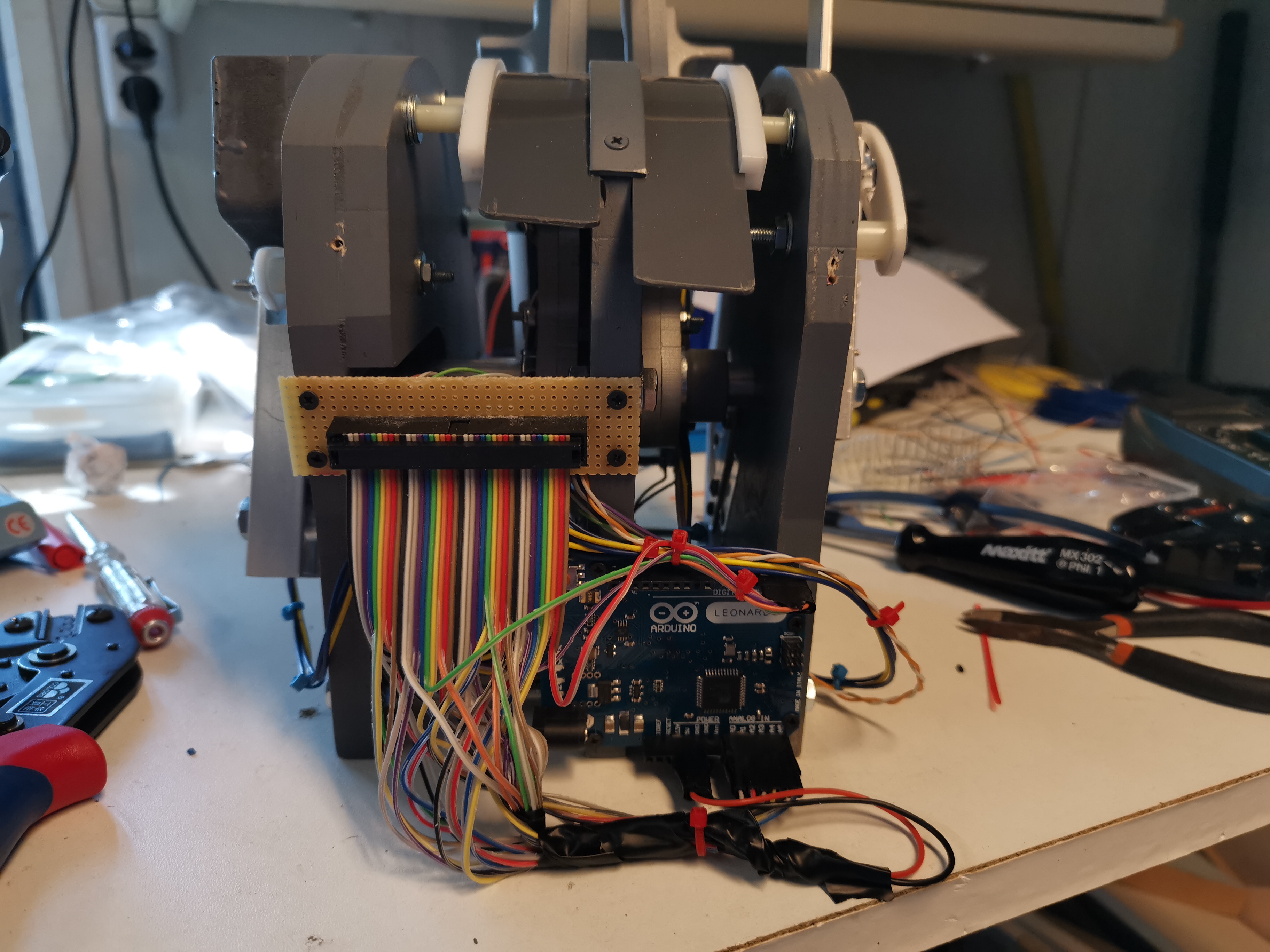
I have been puzzeling a while with the Arduino's
If you use several Arduino Leonardo (or micro's) this is no problem for windows, but P3D can get confused.
I experienced that sometimes analog axis are configured on the wrong Arduino.
So it is a matter of removing unused com ports of the arduino in windows and connect Arduino's to the same USB ports.
I will add my Arduino topic on that.
I switched to the Leonardo version, the Micro's are very small and mounting is not easy.
So this is also ready and functioning great.![]()
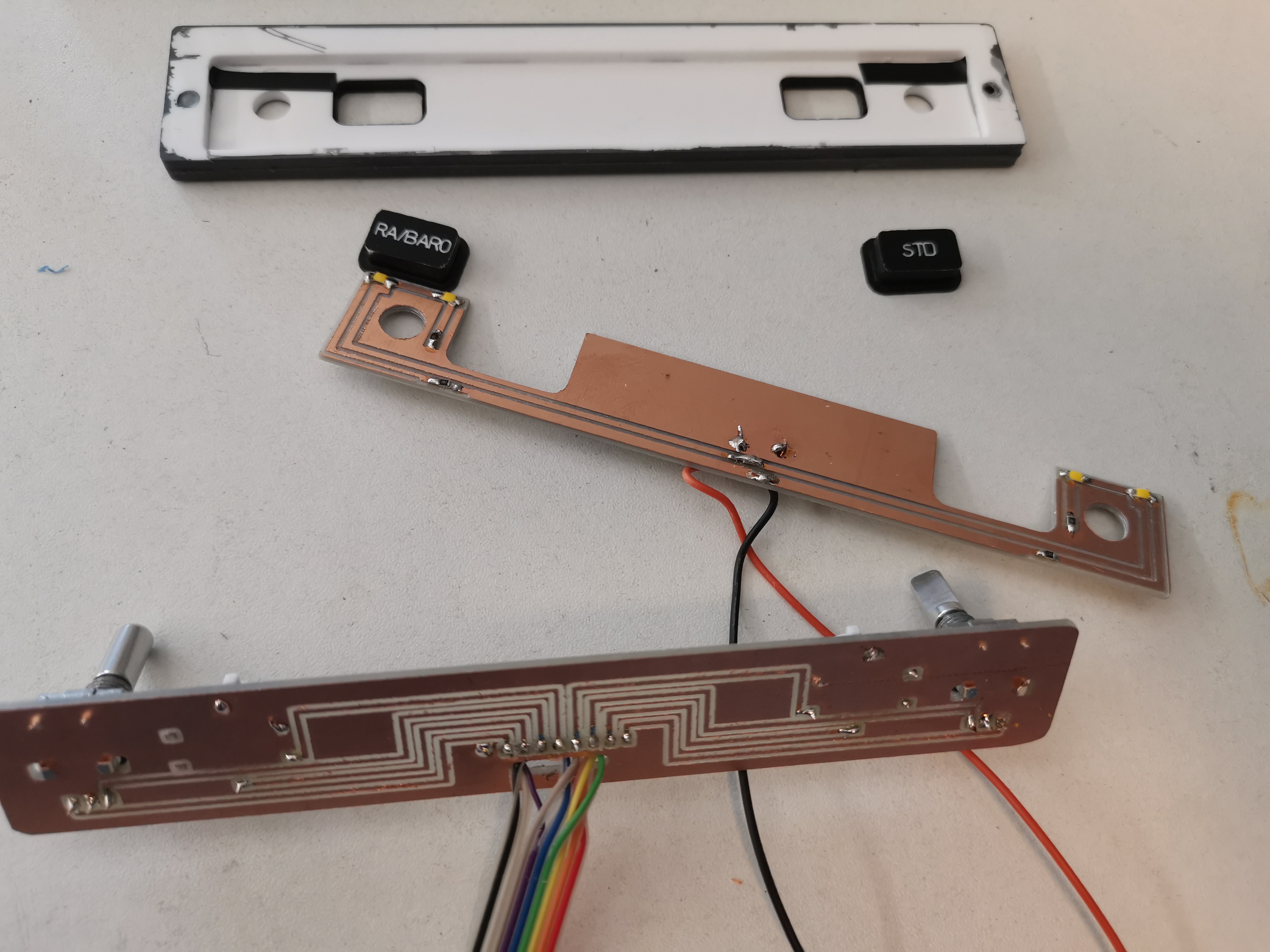
![]()
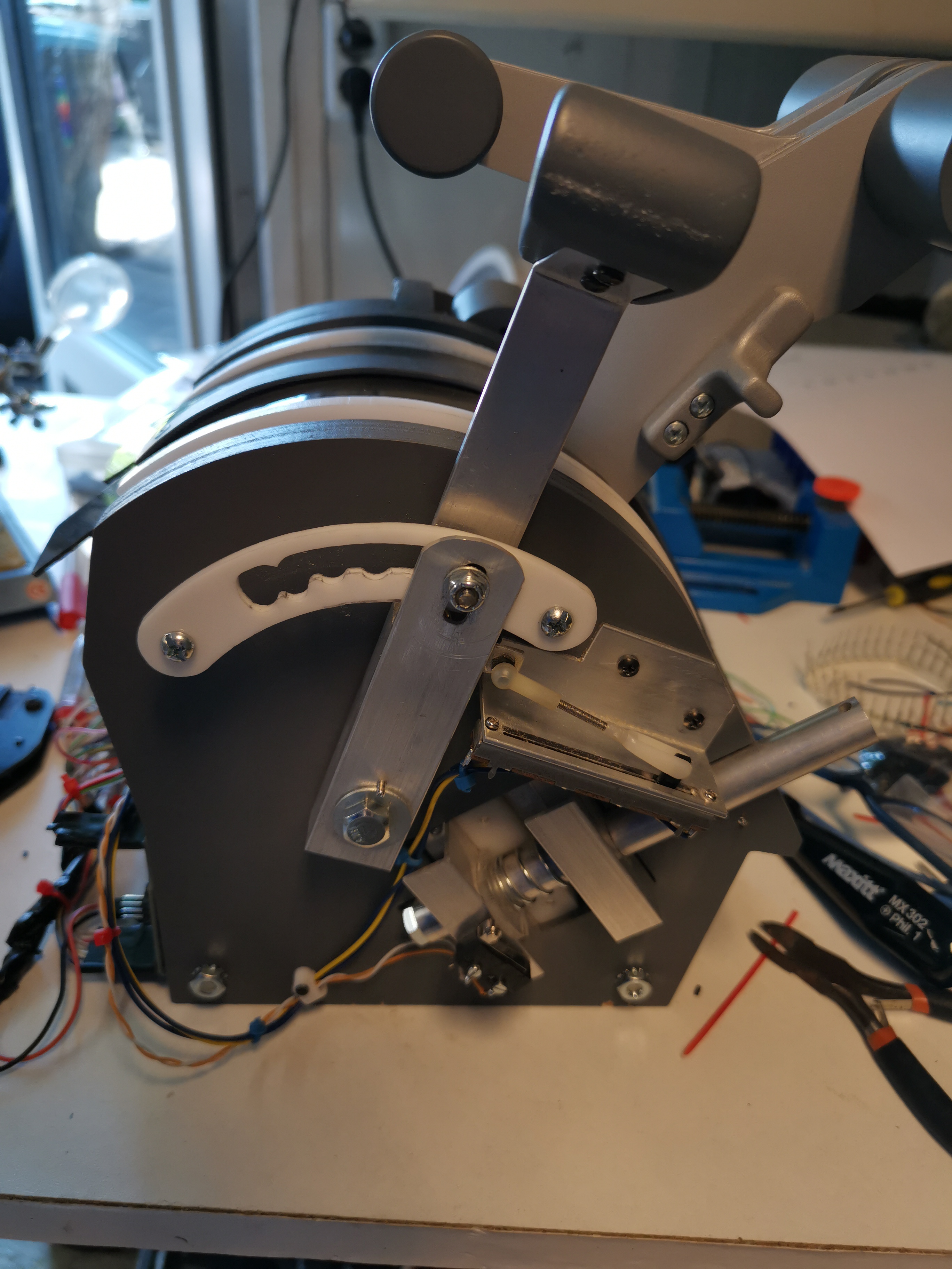
Since i made all parts myself it took a while, but it was fun to do, and i learned a lot about materials for use with my CNC machine.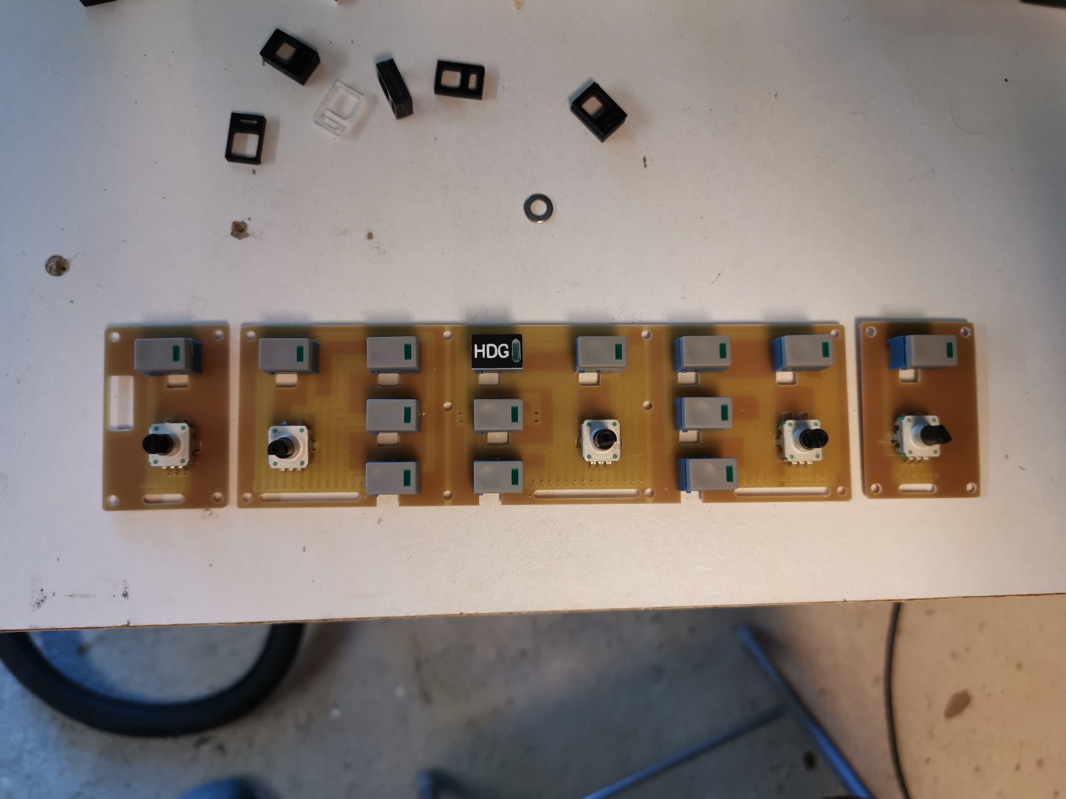
I used 3 mm acryllic for the buttons caps and milled several layers to produce one button caps which i glued together.
it took some experimenting but they are satisfying now.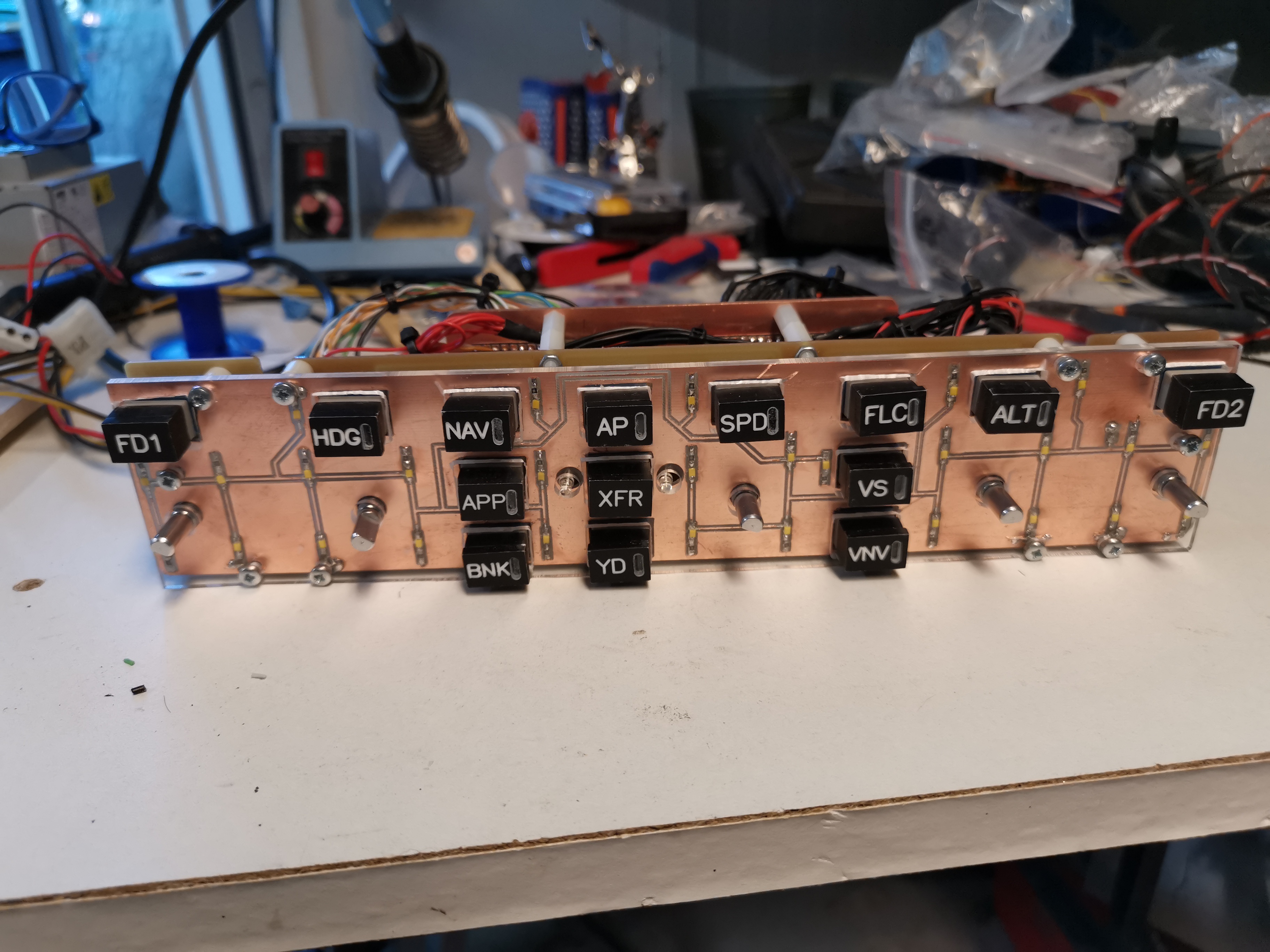
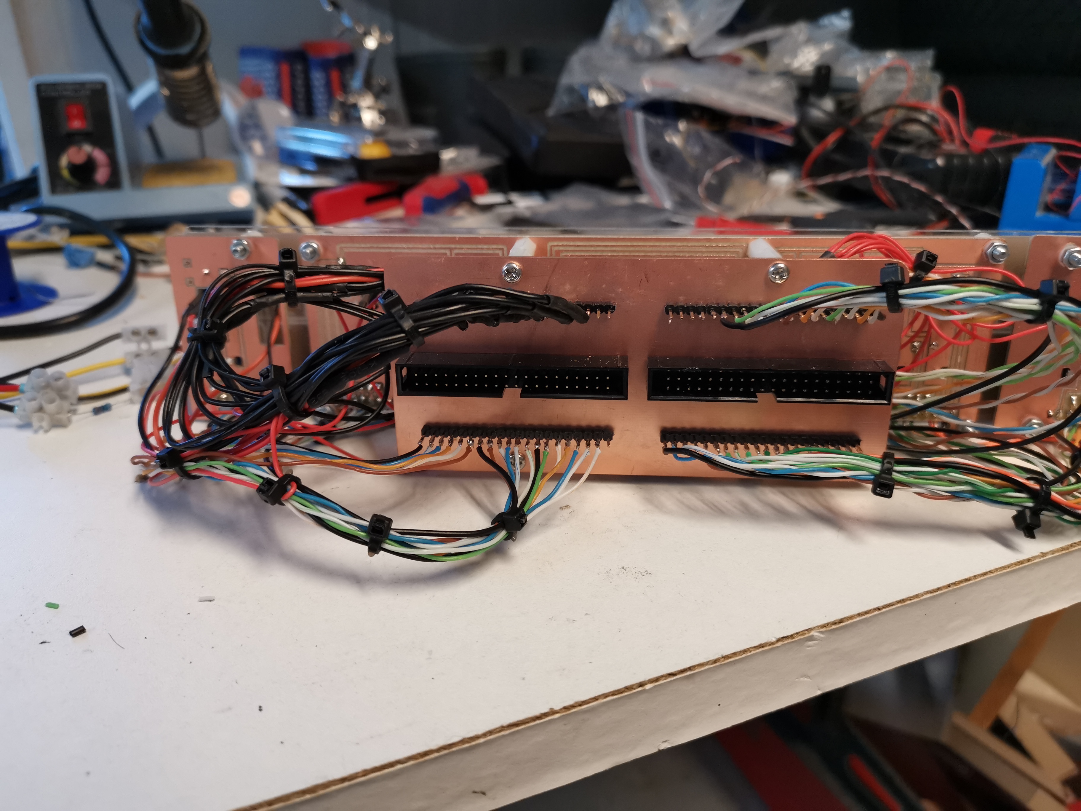
Here i connect flatcabels which are connected to a Arduino Mega .
It is easy to detach like this.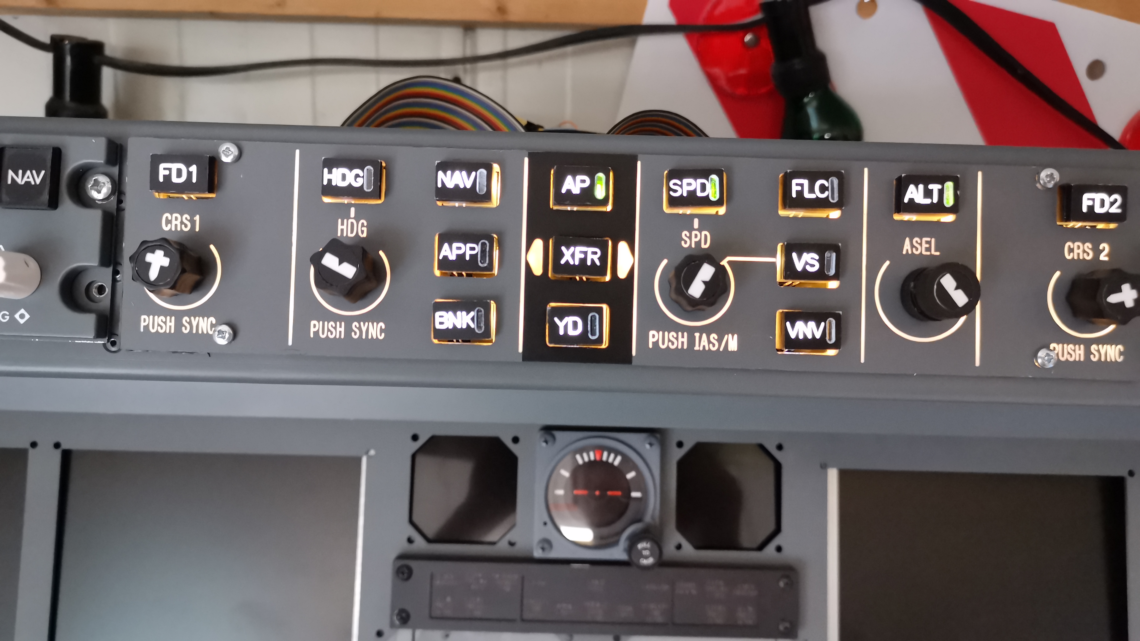
Permanent mounting in the MIP still needs to be done , so this still looks a bit messy.
Since i made all parts myself it took a while, but it was fun to do, and i learned a lot about materials for use with my CNC machine.
I used 3 mm acryllic for the buttons caps and milled several layers to produce one button caps which i glued together.
it took some experimenting but they are satisfying now.
Here i connect flatcabels which are connected to a Arduino Mega .
It is easy to detach like this.
Permanent mounting in the MIP still needs to be done , so this still looks a bit messy.![]()
![]()
All is selfmade which takes a while , but i like designing these panels.
I used for the backlights of the pushbuttons microswitches with a led.
They are cheap and only light the button not the panel.
For the panel backlight i desisgned a pcb with smb led's.
The panel matches the other panels with soft white color for the panel and bright white for the buttons.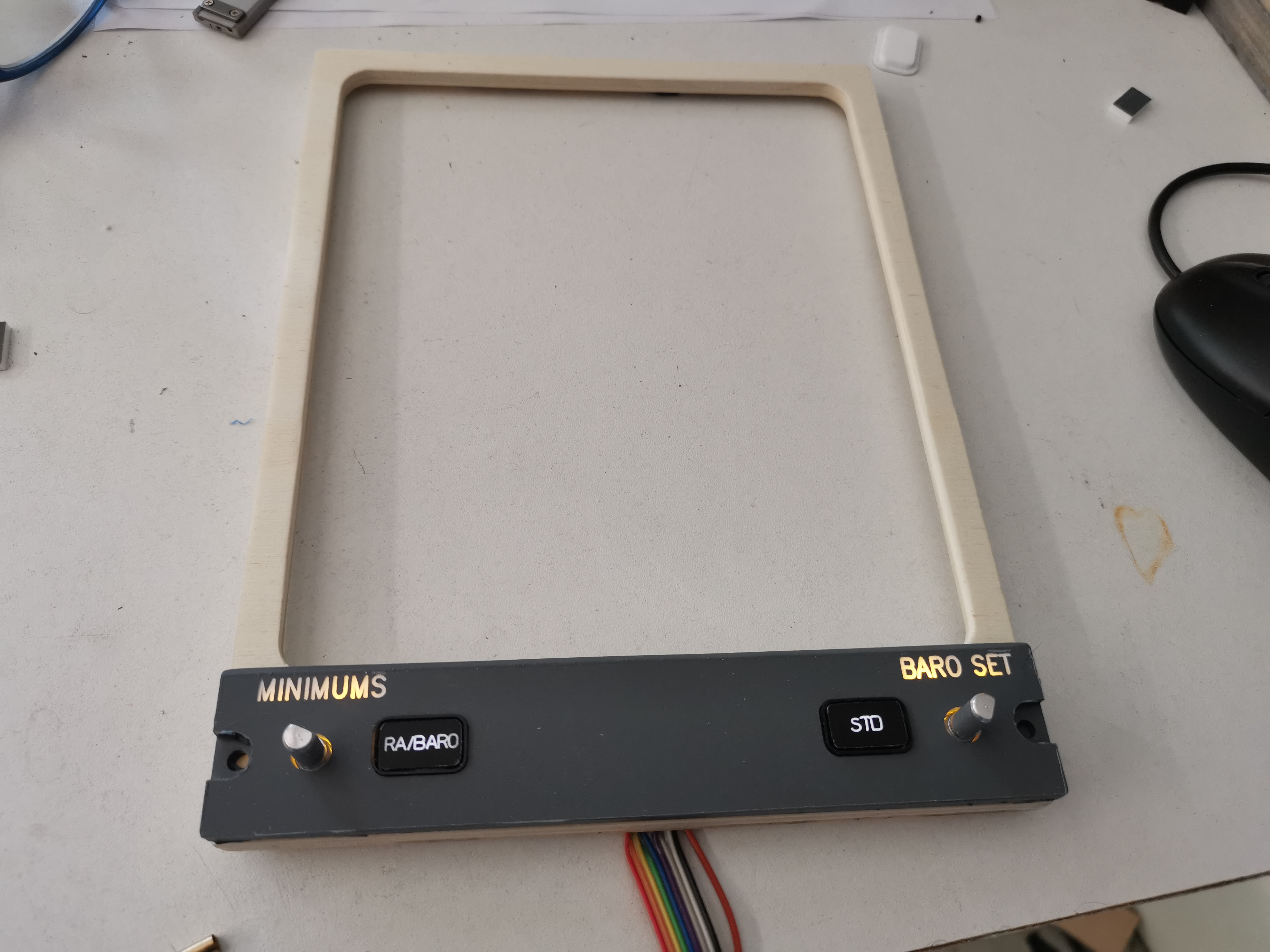
All is selfmade which takes a while , but i like designing these panels.
I used for the backlights of the pushbuttons microswitches with a led.
They are cheap and only light the button not the panel.
For the panel backlight i desisgned a pcb with smb led's.
The panel matches the other panels with soft white color for the panel and bright white for the buttons.![]()
This also took more time as expected, but all is functioning and fits well in the mip now.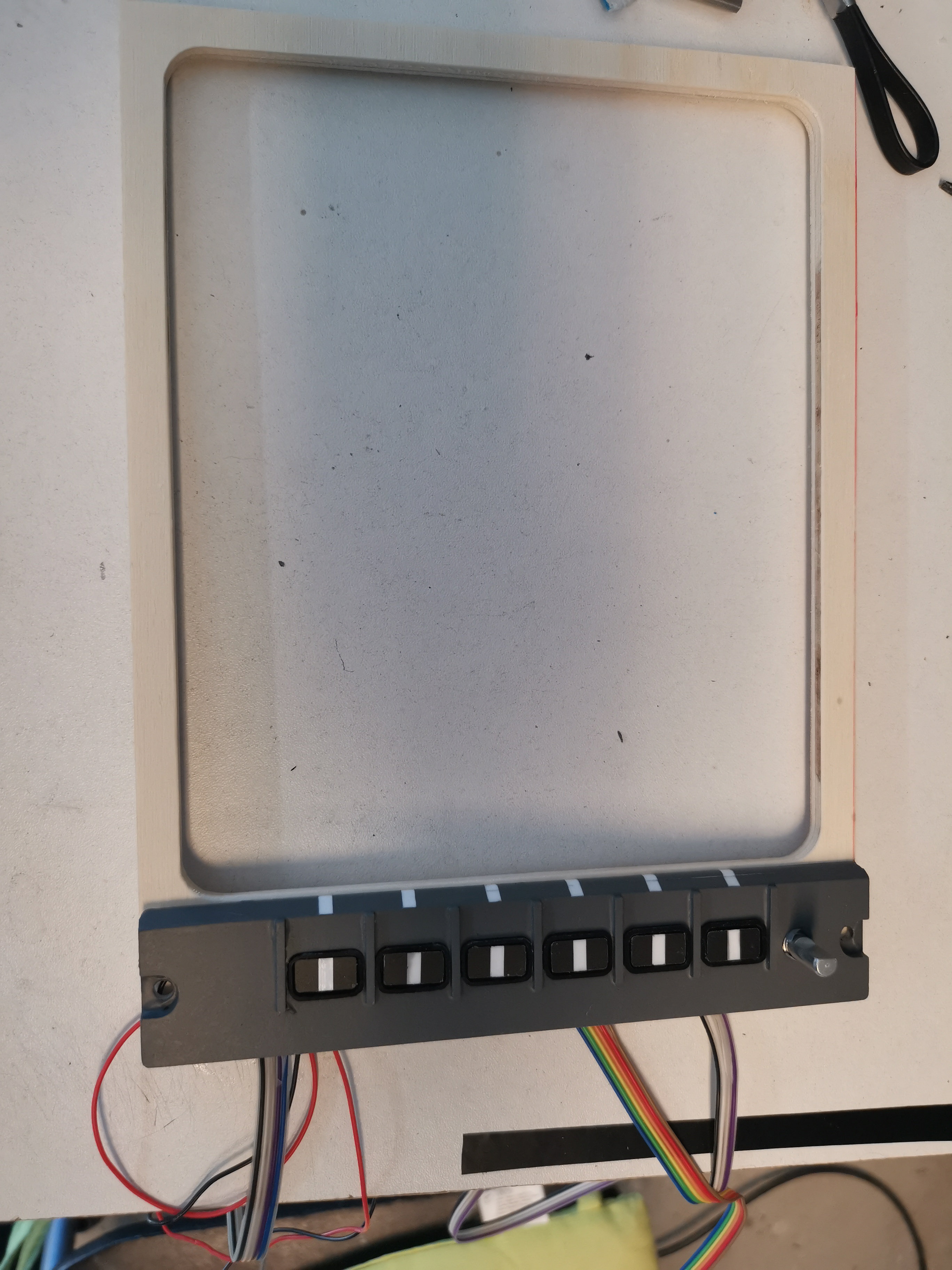
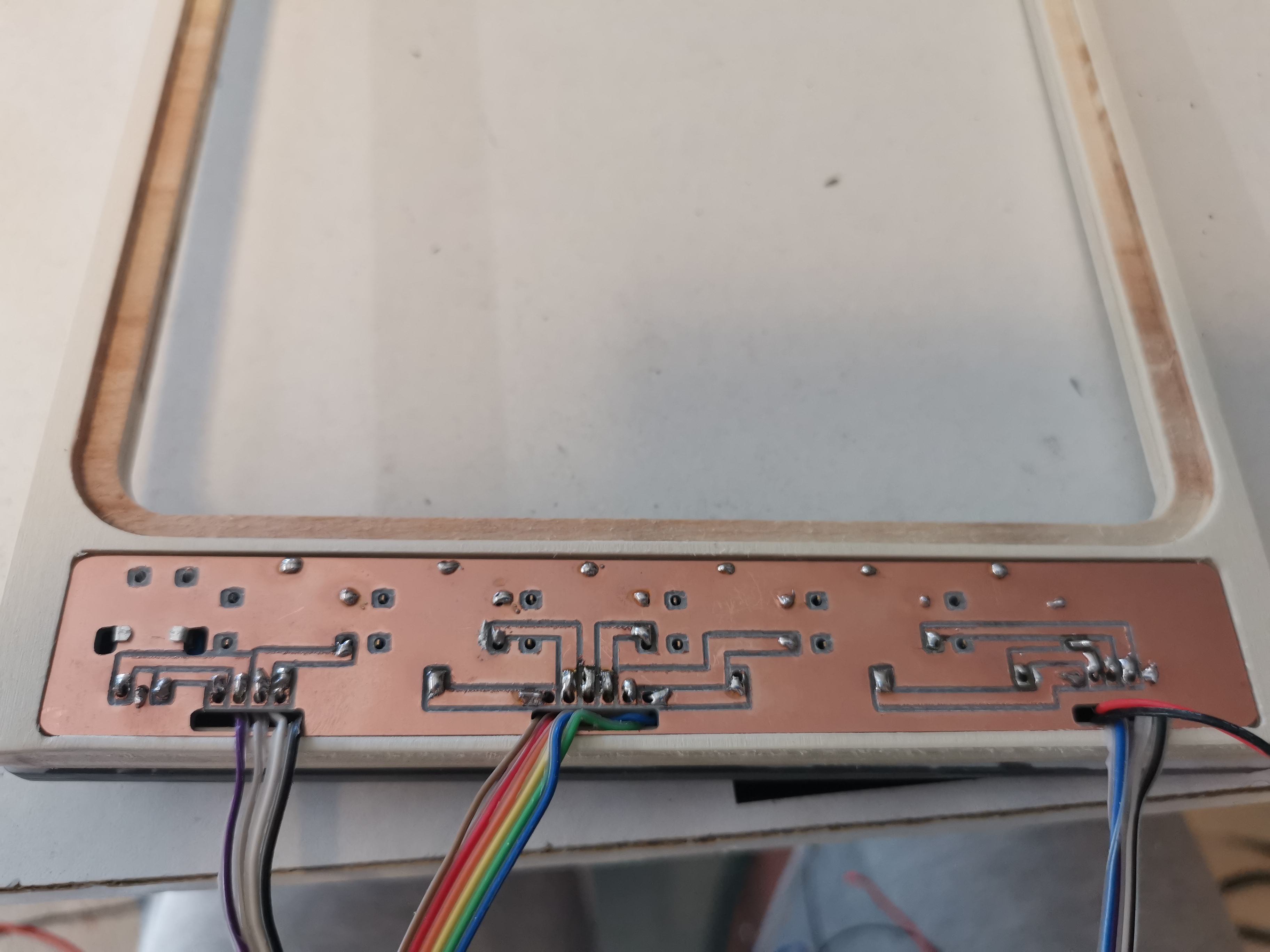
This also took more time as expected, but all is functioning and fits well in the mip now.![]()
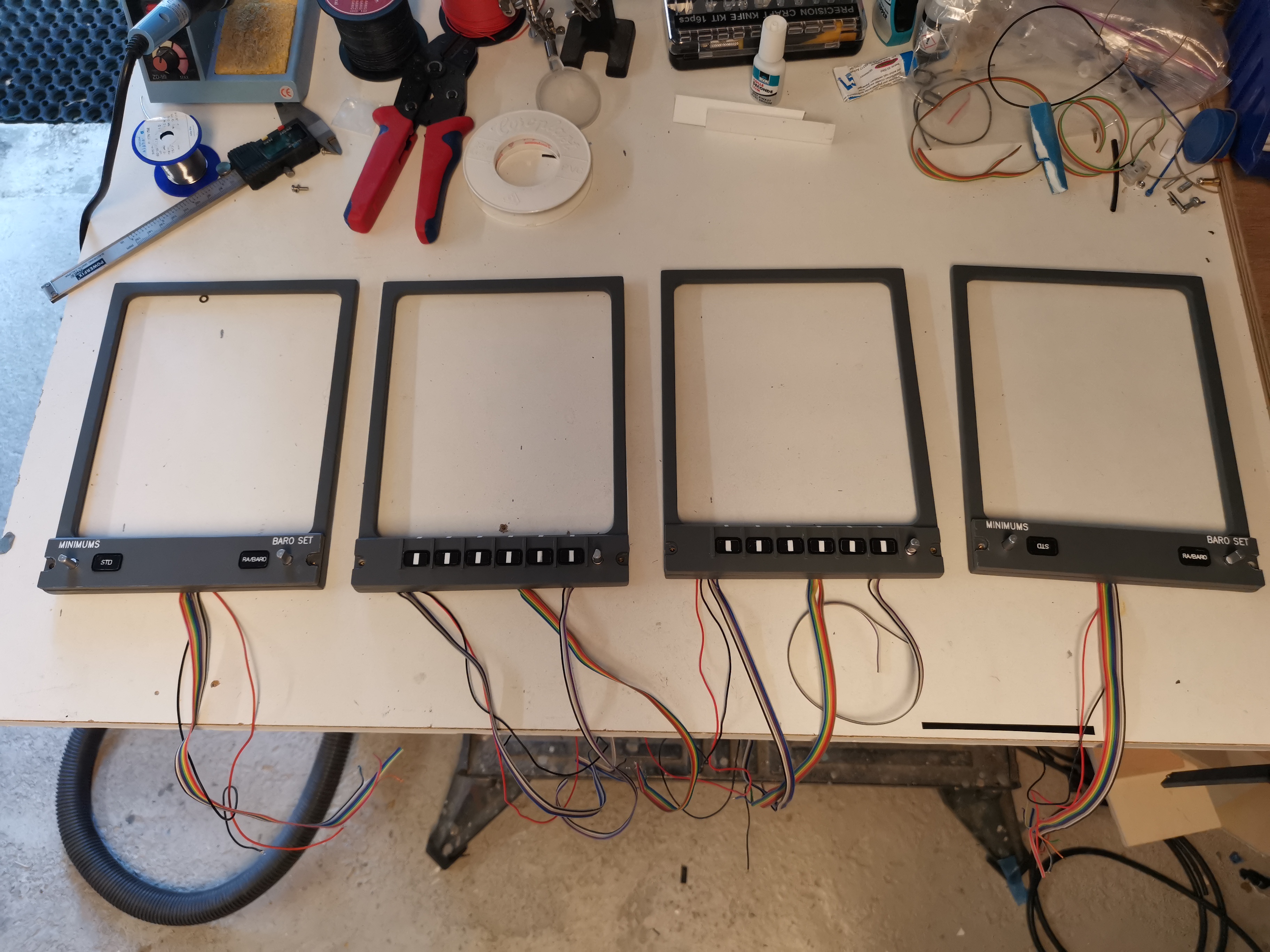
![]()
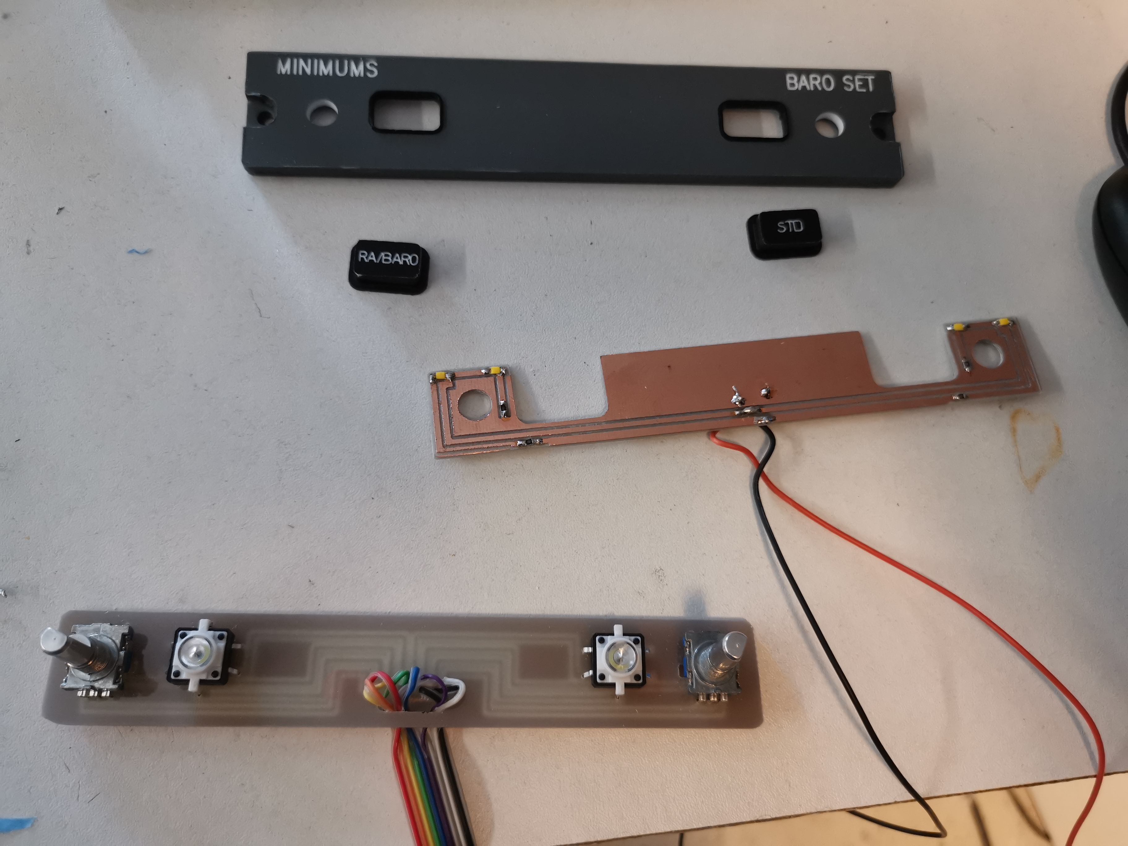
Also i made it all, knobs, bezels, panels, pcb's.
So sometimes things mess up and you have to start over again...but it is fun to do!
Also i made it all, knobs, bezels, panels, pcb's.
So sometimes things mess up and you have to start over again...but it is fun to do!![]()
I creates all parts with my CNC machine, and ordered stickers for the dialplate.
A little amber Led illuminates it all.
With mobiflight it is easy to interface the gauge with Arduino.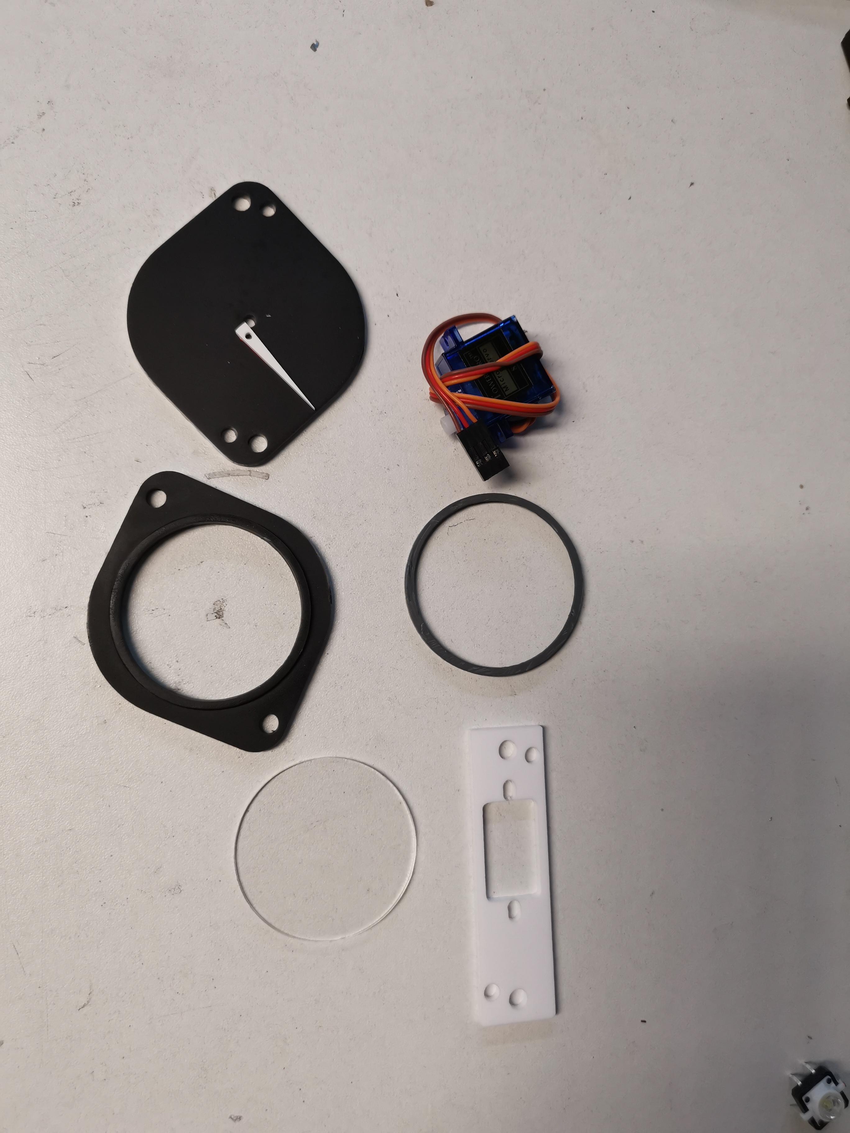
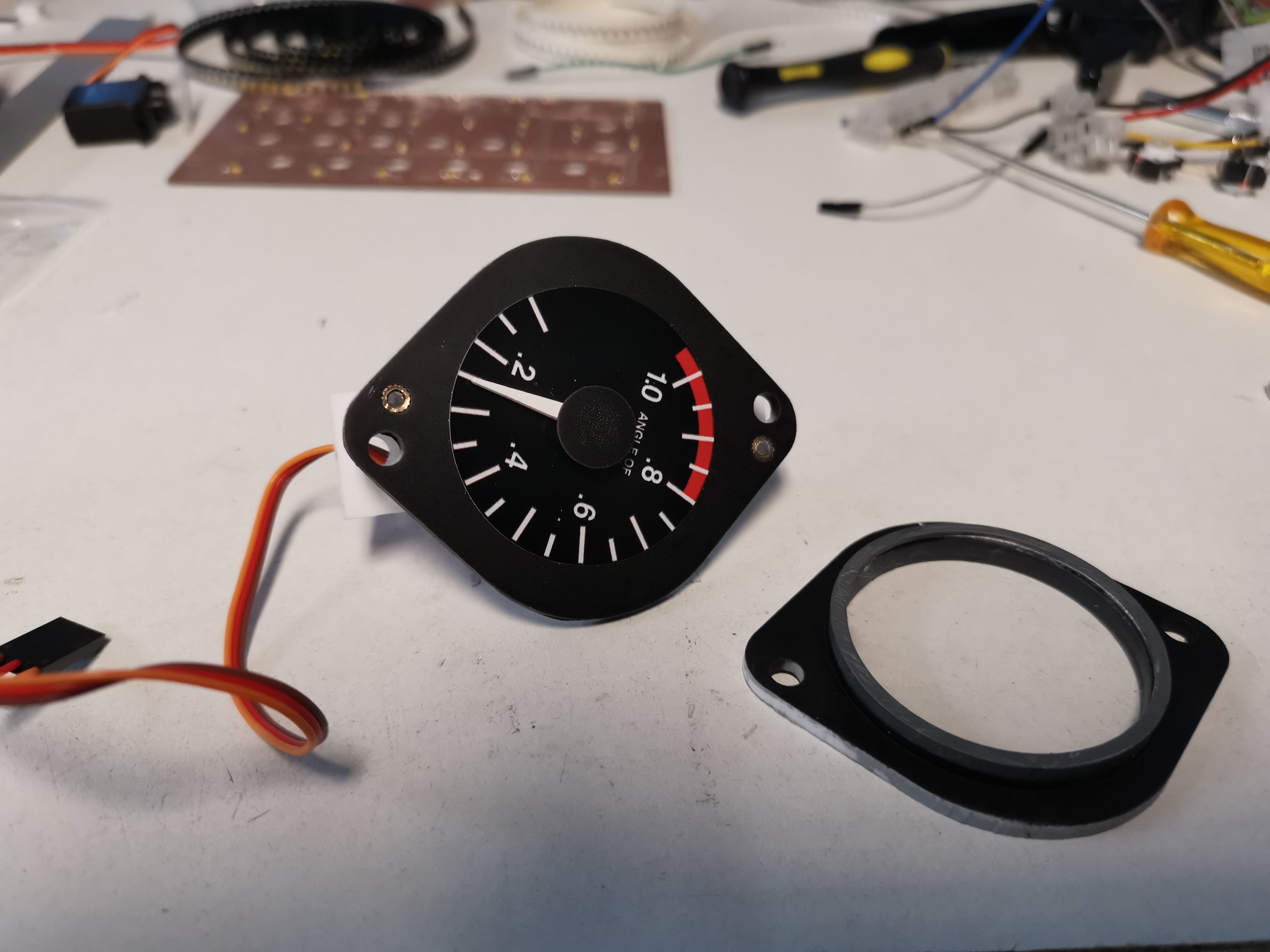
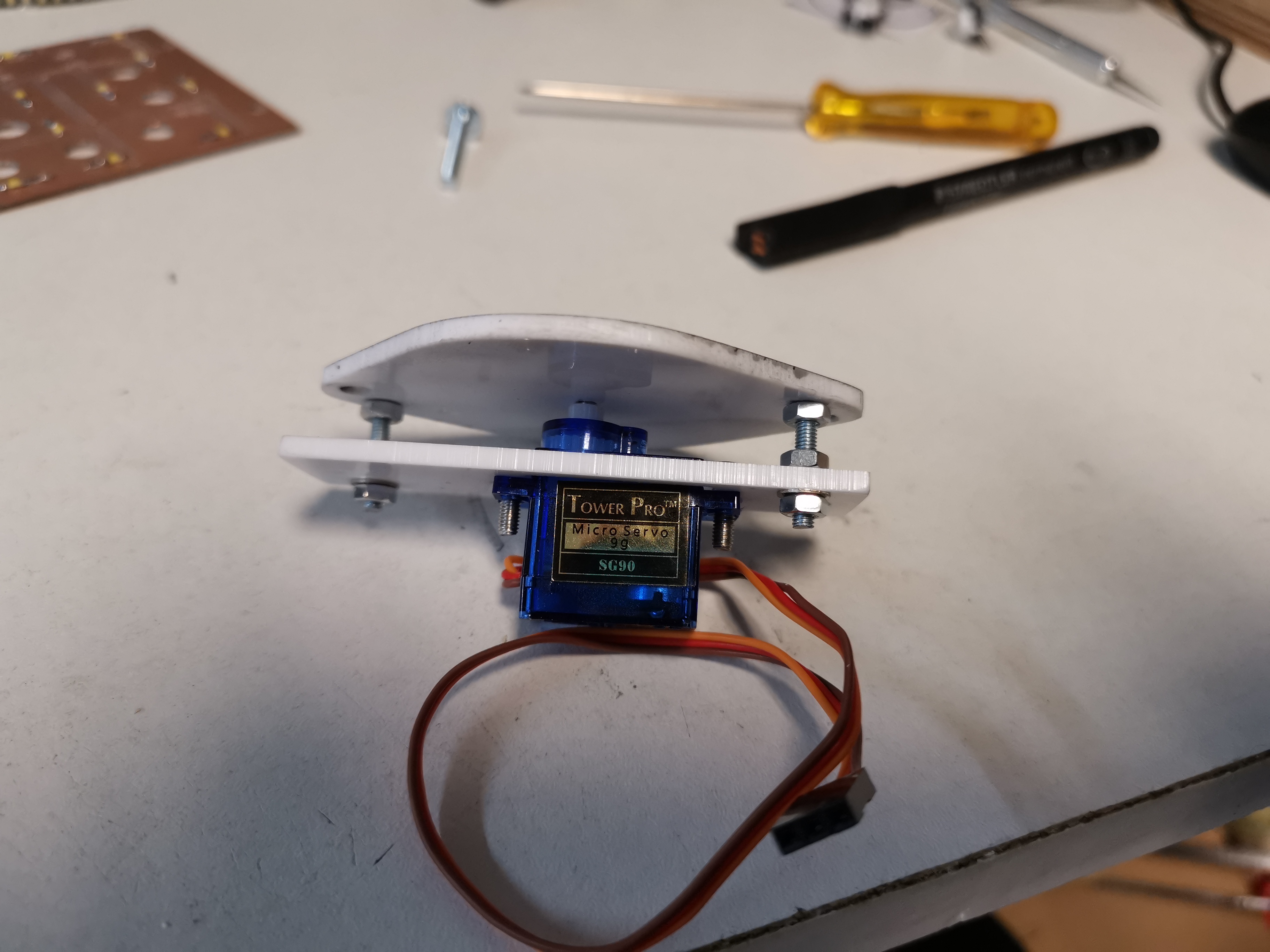
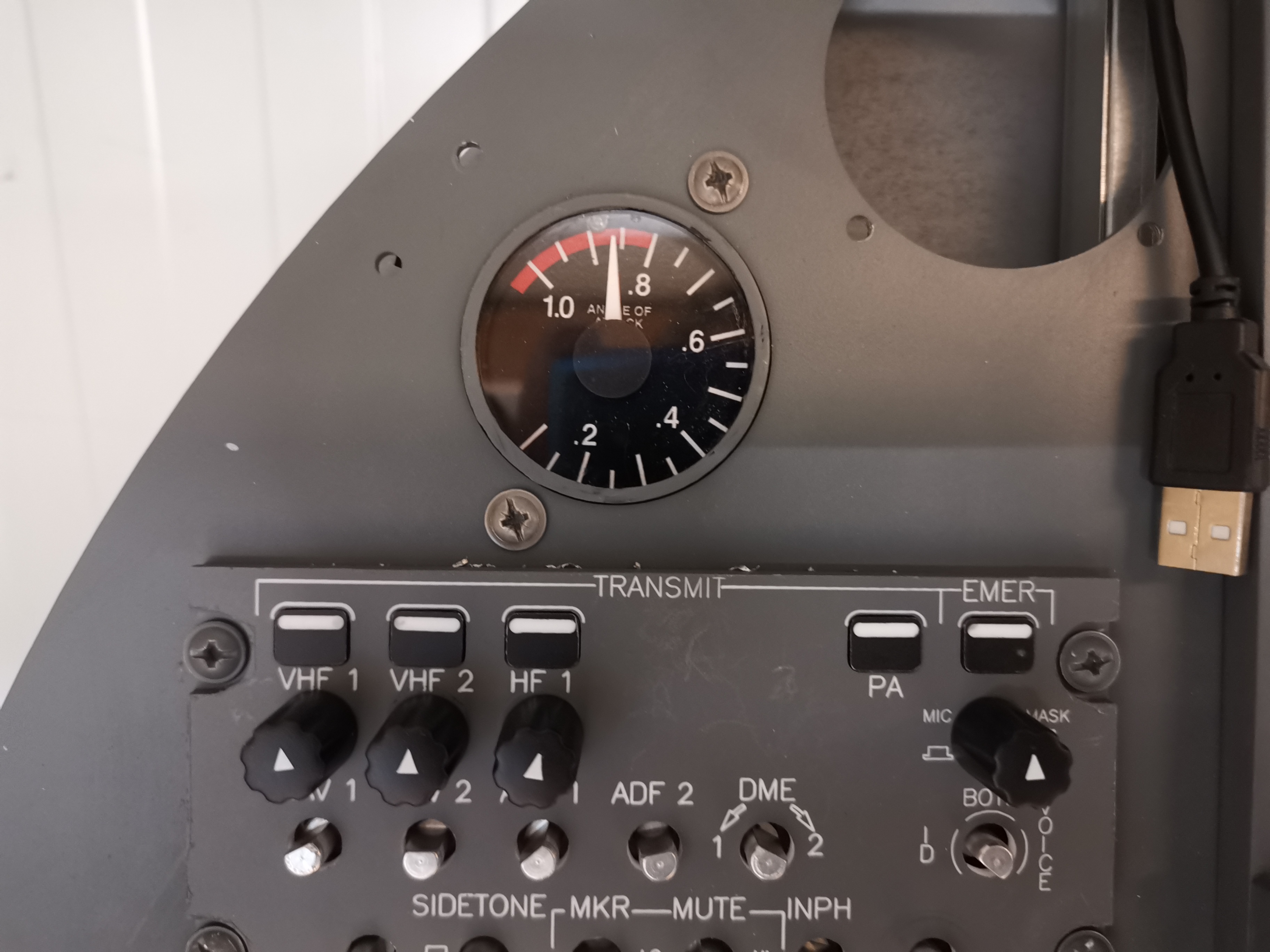
I creates all parts with my CNC machine, and ordered stickers for the dialplate.
A little amber Led illuminates it all.
With mobiflight it is easy to interface the gauge with Arduino.![]()
Forum NavigationRoel's Learjet 45 simulator
![]() #91 · April 27, 2020, 4:53 am
#91 · April 27, 2020, 4:53 am![]() #92 · April 27, 2020, 7:59 am
#92 · April 27, 2020, 7:59 am![]() #93 · July 2, 2020, 4:01 am
#93 · July 2, 2020, 4:01 am![]() #94 · July 2, 2020, 6:47 amRoel has reacted to this post.Roel
#94 · July 2, 2020, 6:47 amRoel has reacted to this post.Roel![]() #95 · July 26, 2020, 10:59 amRon Rollo has reacted to this post.Ron Rollo
#95 · July 26, 2020, 10:59 amRon Rollo has reacted to this post.Ron Rollo![]() #96 · August 25, 2020, 4:37 am
#96 · August 25, 2020, 4:37 am![]() #97 · August 25, 2020, 6:31 amRoel has reacted to this post.Roel
#97 · August 25, 2020, 6:31 amRoel has reacted to this post.Roel![]() #98 · August 25, 2020, 6:37 am
#98 · August 25, 2020, 6:37 am![]() #99 · September 28, 2020, 7:55 am
#99 · September 28, 2020, 7:55 am![]() #100 · September 28, 2020, 12:47 pm
#100 · September 28, 2020, 12:47 pm
2017-10-10