


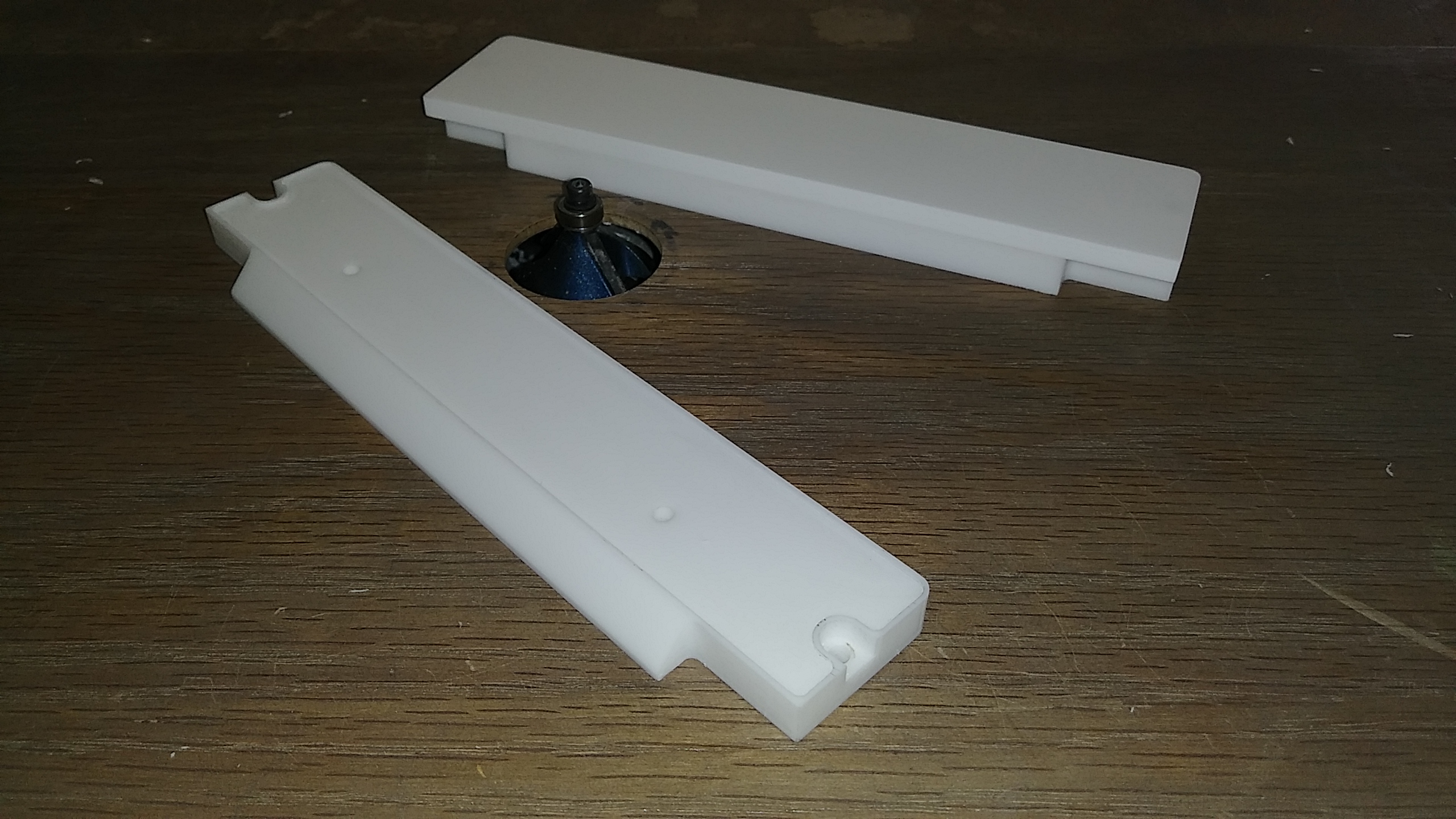
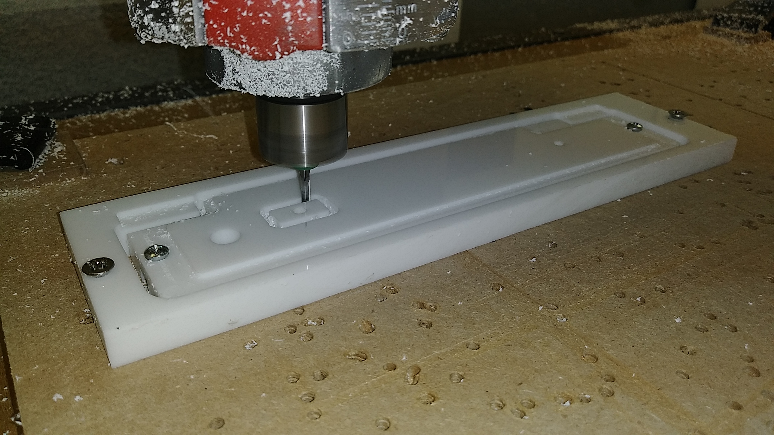
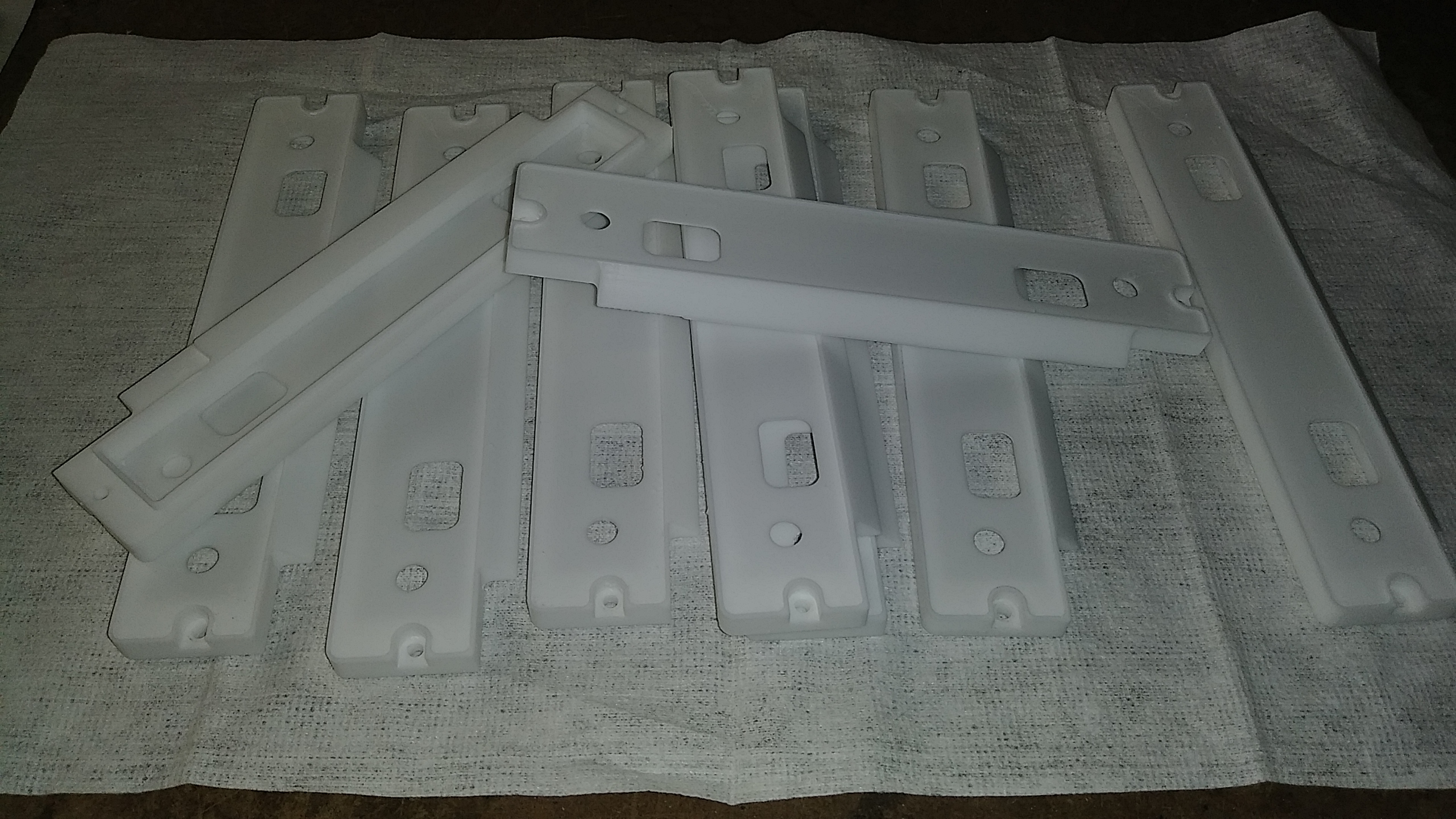
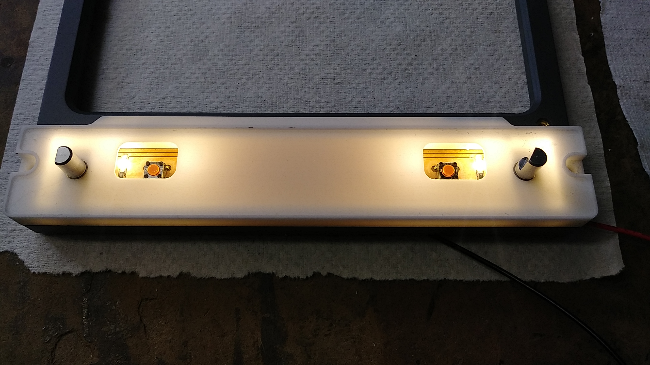
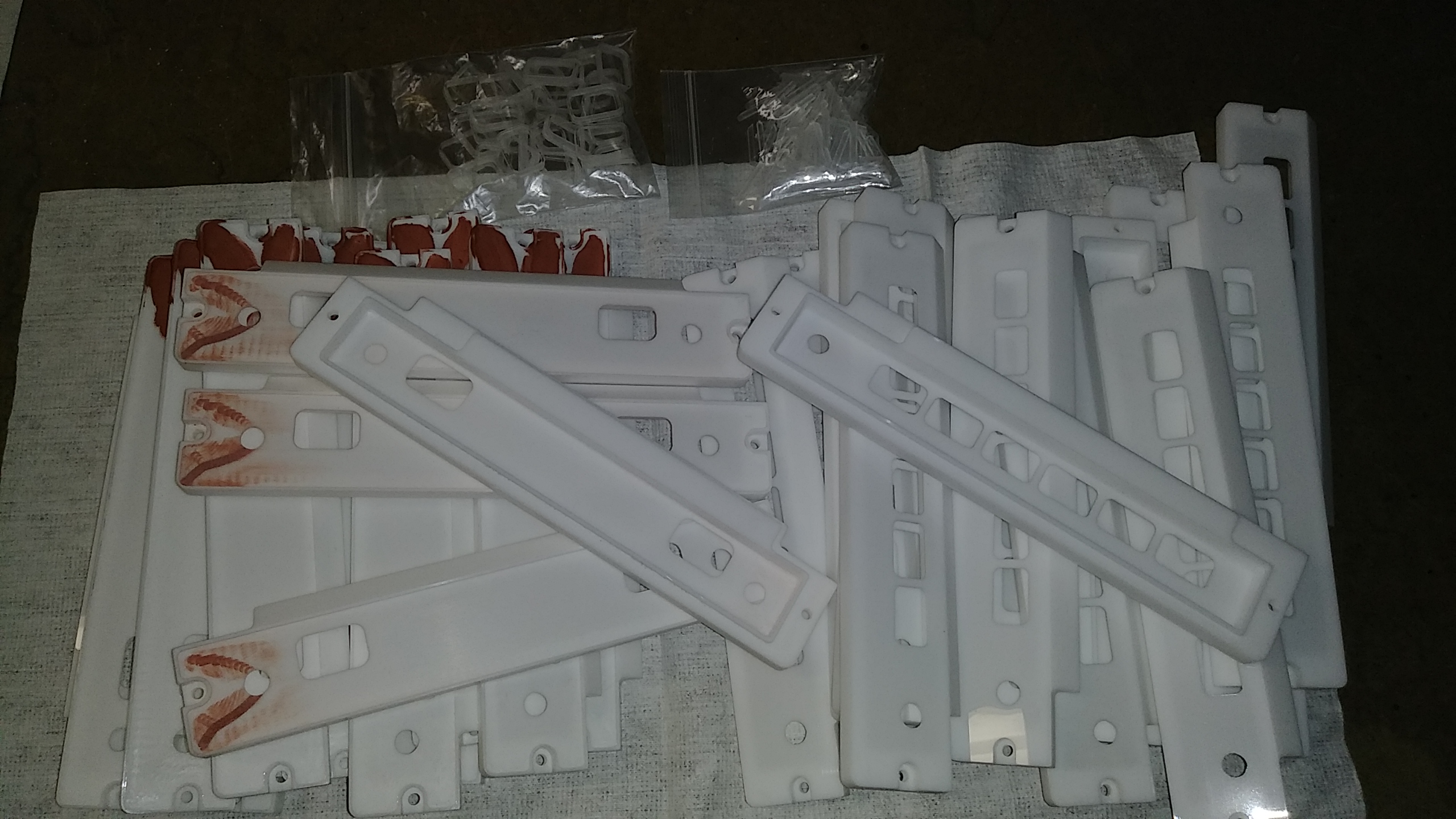
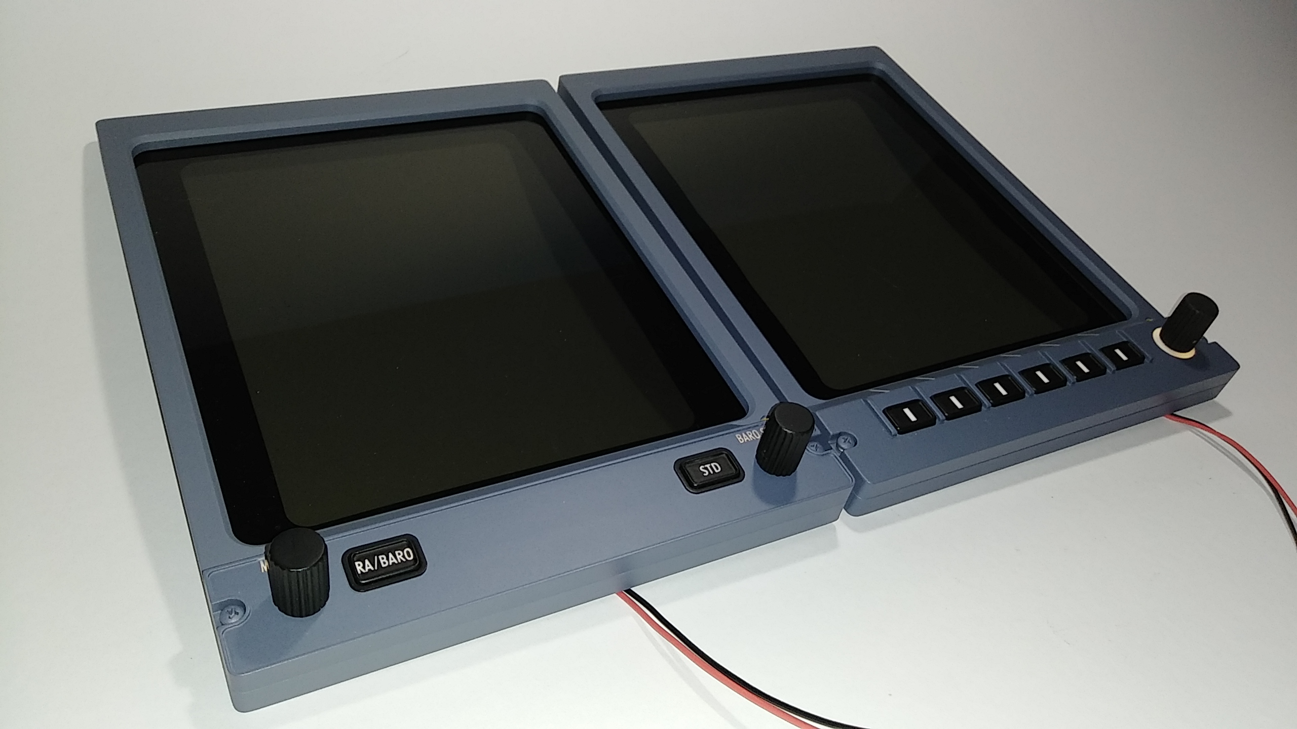
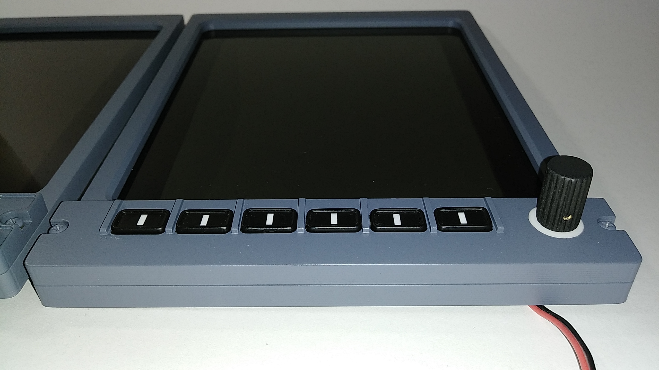
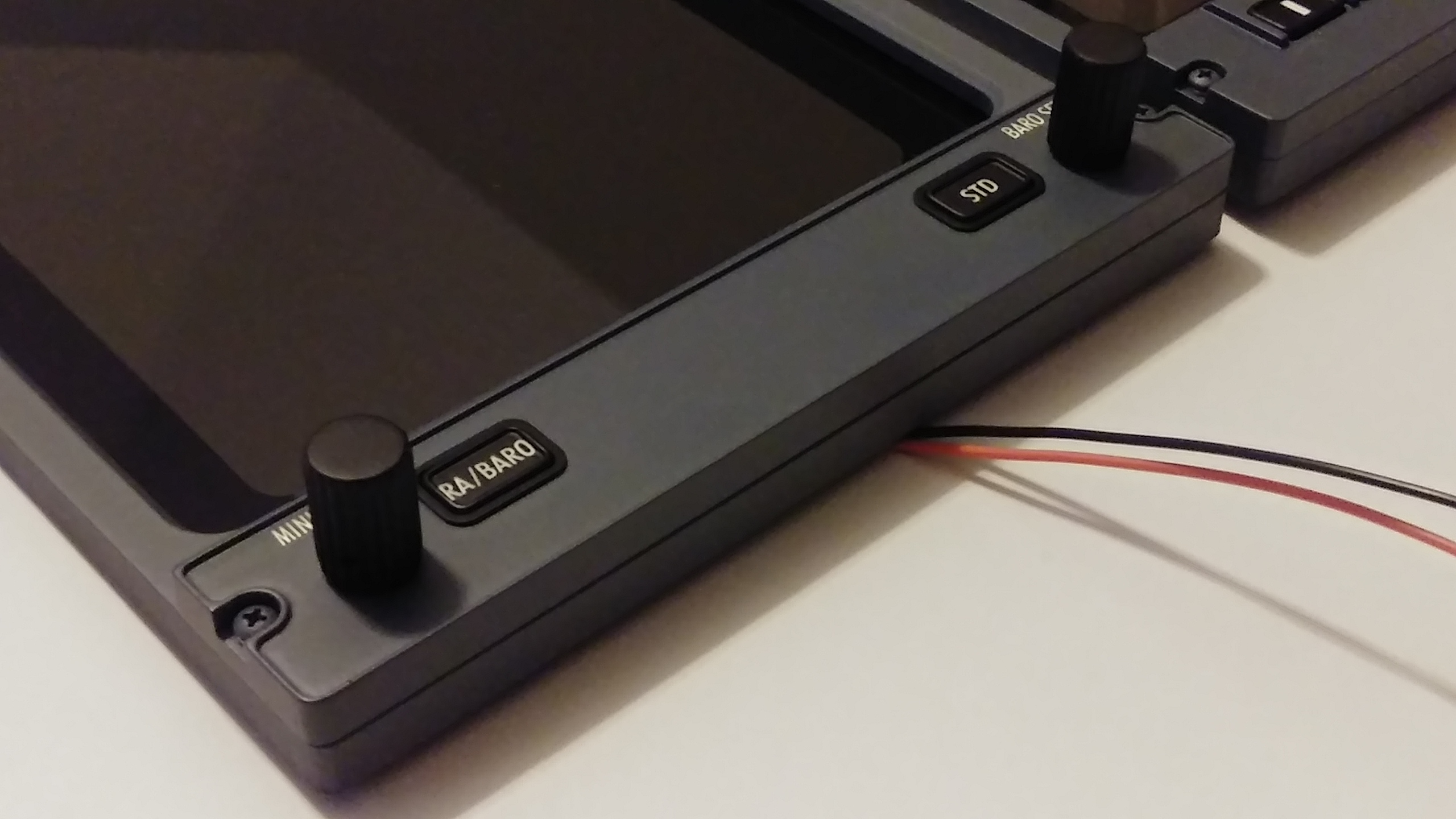
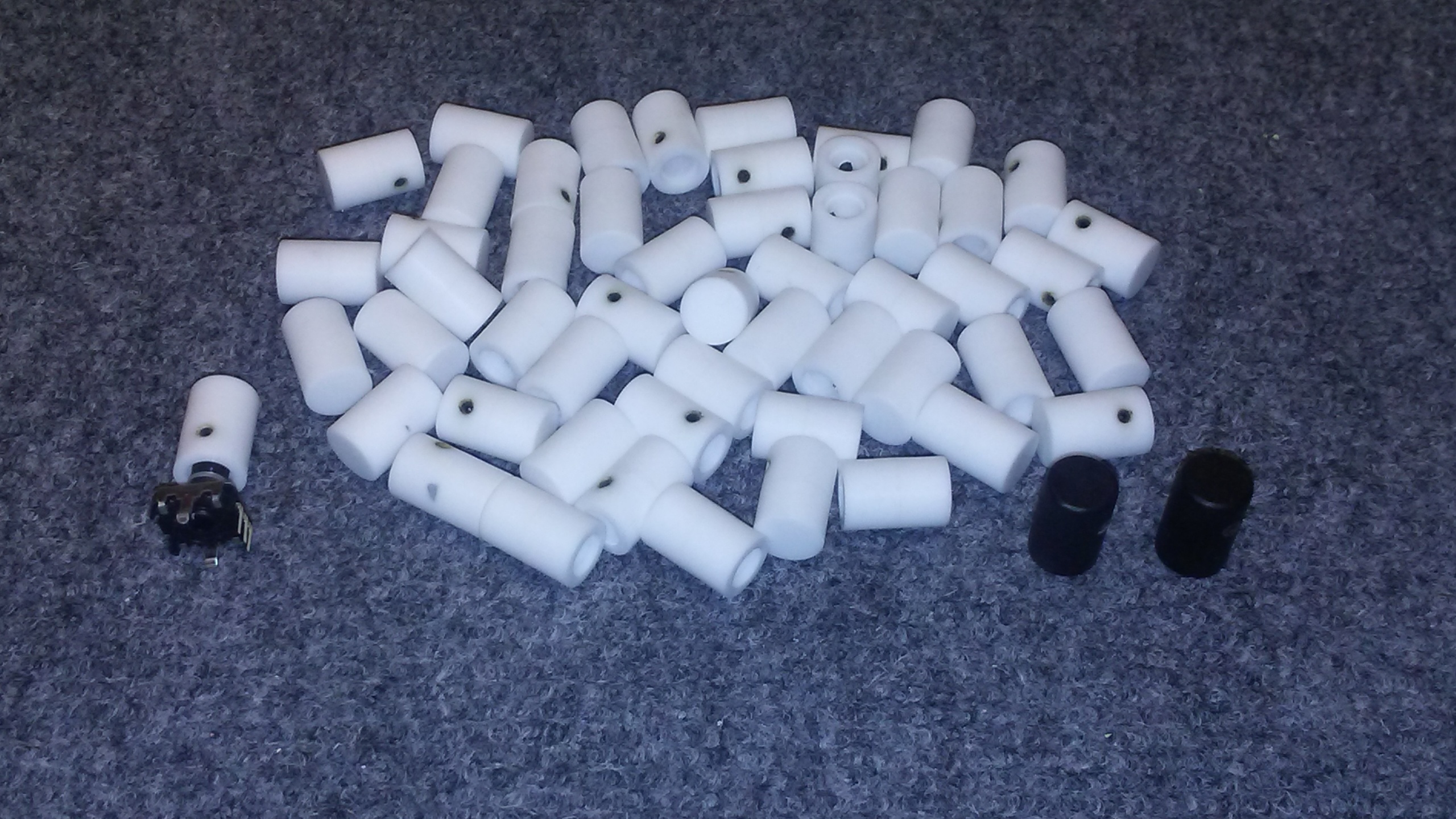
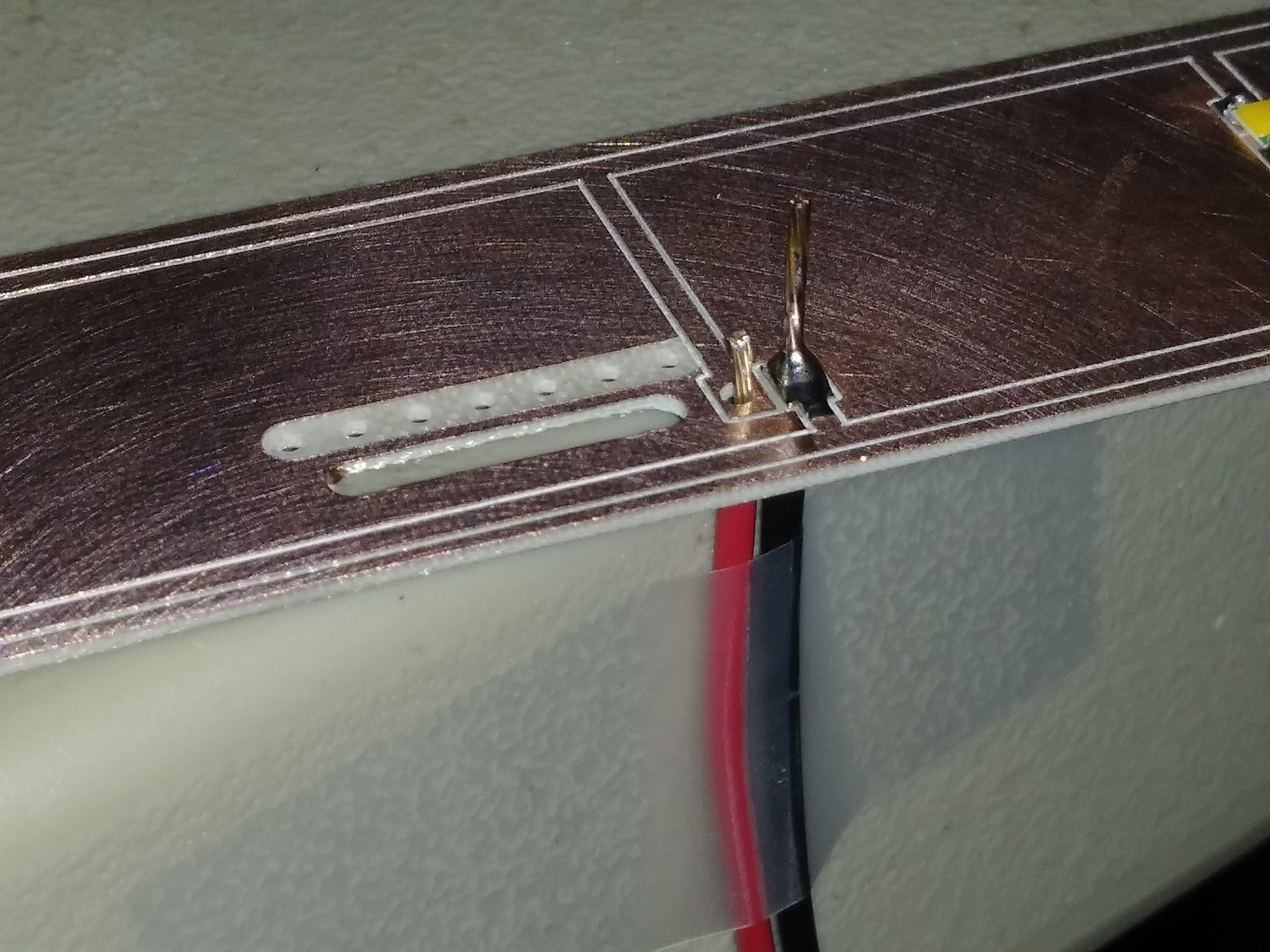
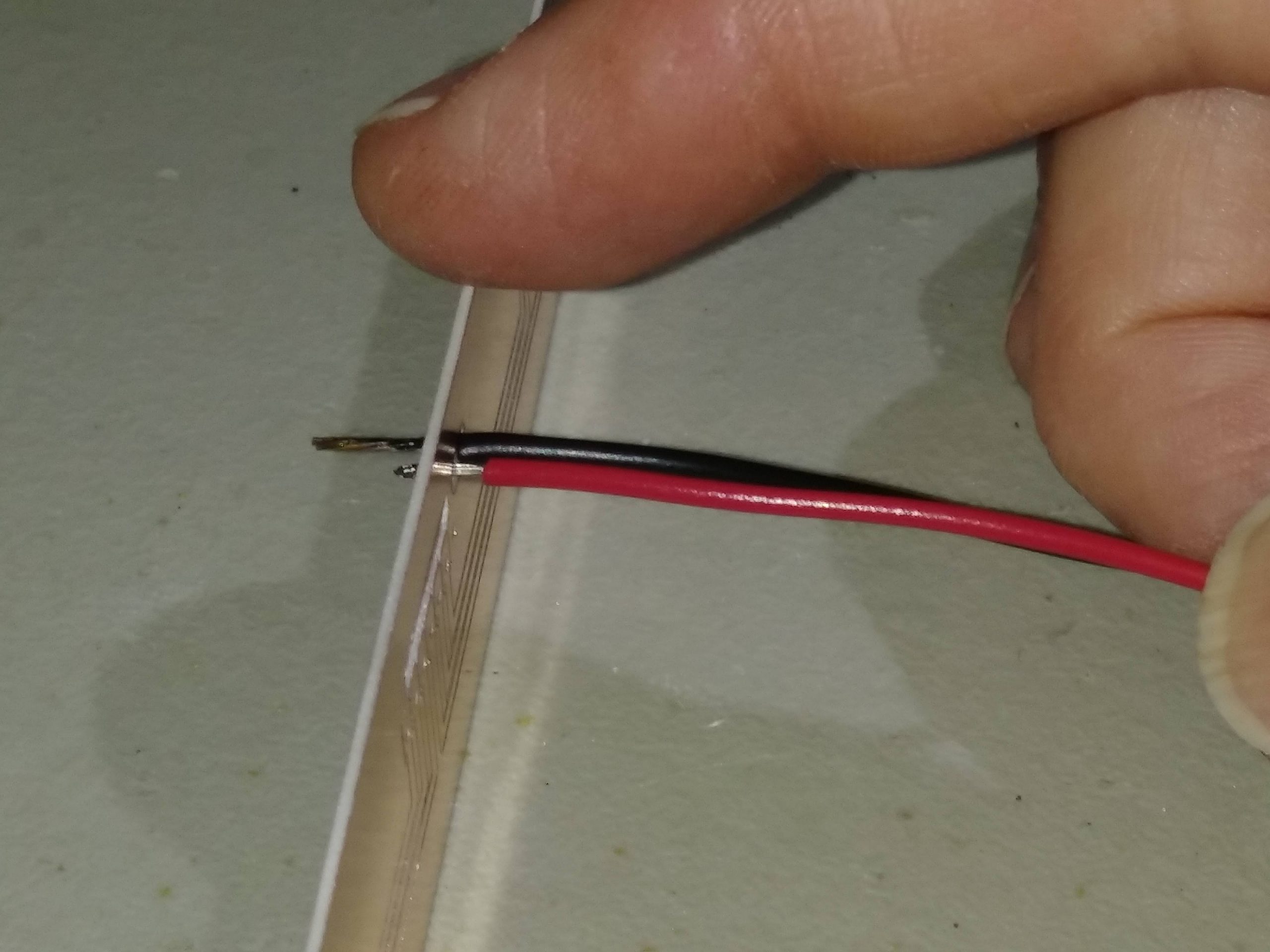
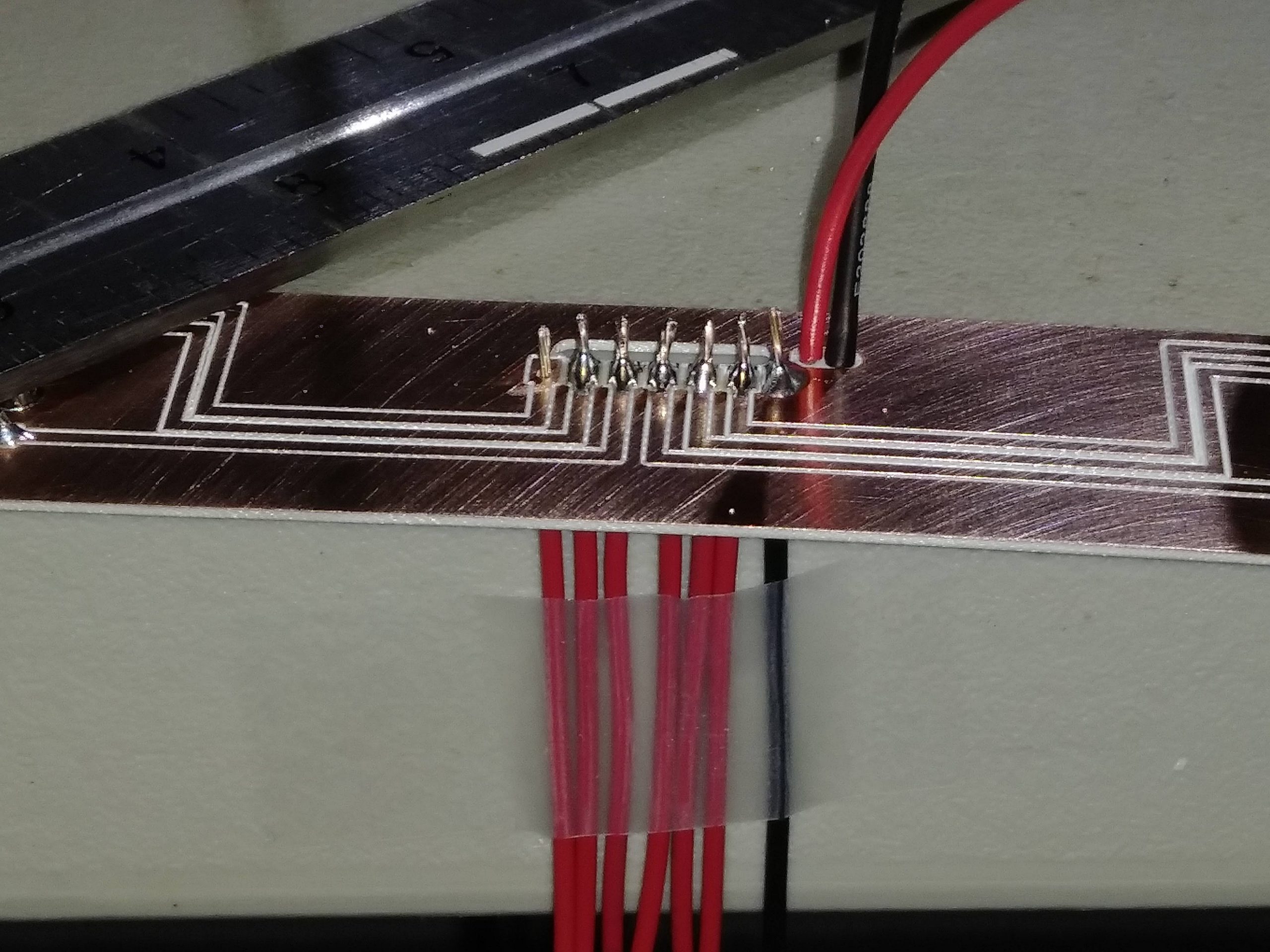
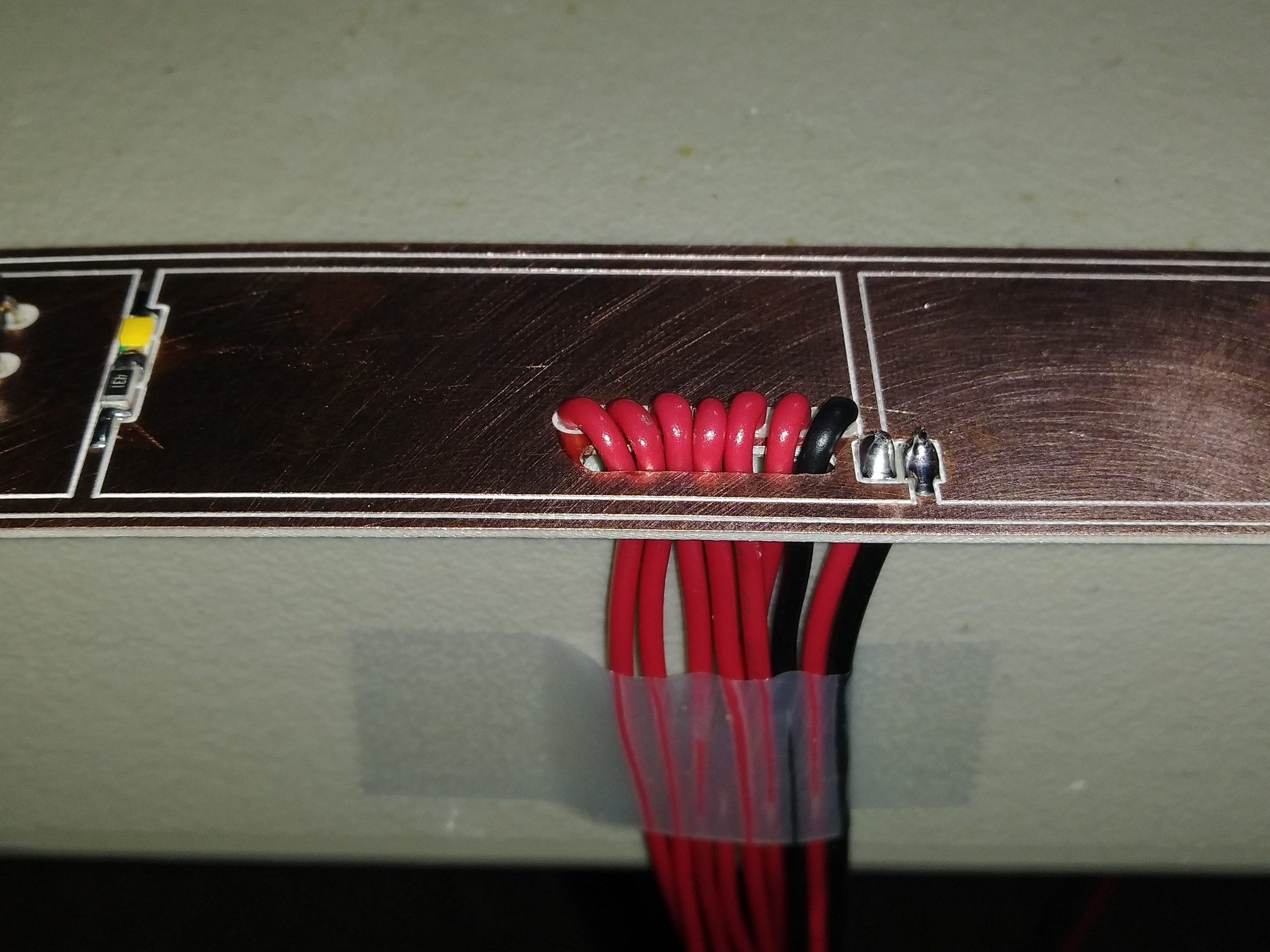
I have finally got to a part of the Display Units that I have to be honest with you, a little worried about, but no more! The DU lower front panels are now well on their way to being completed. Over the past week I have just about completed all the DU1&4 lower front panels. (Remember DU2&3 is a different design) Because of the complexity of these pieces, they have to be milled on the front side, the top side to create the 45 degree edge and then last but not least the back side. In this photo, the front face of the DU1&4 lower panels have already been milled. I have a .03" relief built into the face which you can see if you look closely. Because I do not have an expensive CNC that comes equipped with a forth rotating axis, I had to think outside of the box and designed a mounting jig to be used with a 45 degree milling bit: Here the part is flipped over and the back side is being milled. Notice I have two screws holding the part in place, however, the very first cut the screws were in the middle two screw holes. In other words, after about eight minutes of cutting, the CNC stops and the screws have to be moved to the outer screw holes to make way for the next cuts. A pain but very effective! Here are several DU1&4 lower panels milled on all three sides: And here is the DU1&4 lower panel lit up and on the DU bezel! I am not sure which DU lower panel set is going to be more challenging. The DU2&3 panel has it's own set of issues that I will need to overcome and those issues are all but handled, I just have to make them next week! Getting closer to having the Display Units completed and delivered! I have finally got to a part of the Display Units that I have to be honest with you, a little worried about, but no more! The DU lower front panels are now well on their way to being completed. Over the past week I have just about completed all the DU1&4 lower front panels. (Remember DU2&3 is a different design) Because of the complexity of these pieces, they have to be milled on the front side, the top side to create the 45 degree edge and then last but not least the back side. In this photo, the front face of the DU1&4 lower panels have already been milled. I have a .03" relief built into the face which you can see if you look closely. Because I do not have an expensive CNC that comes equipped with a forth rotating axis, I had to think outside of the box and designed a mounting jig to be used with a 45 degree milling bit: Here the part is flipped over and the back side is being milled. Notice I have two screws holding the part in place, however, the very first cut the screws were in the middle two screw holes. In other words, after about eight minutes of cutting, the CNC stops and the screws have to be moved to the outer screw holes to make way for the next cuts. A pain but very effective! Here are several DU1&4 lower panels milled on all three sides: And here is the DU1&4 lower panel lit up and on the DU bezel! I am not sure which DU lower panel set is going to be more challenging. The DU2&3 panel has it's own set of issues that I will need to overcome and those issues are all but handled, I just have to make them next week! Getting closer to having the Display Units completed and delivered! Real quick update on the Display Units! All the lower DU panels are cut front and back, now to sand them and cut the inside 45 degree angles in DU's 2 and 3. I have not yet figured that out yet but I am working on it. Hopefully I will have that resolved by next week. The photos above has 32 DU lower panels in it! Additionally, I have the button bezels for DU14 cut out and the button dividers for DU23 in small bags at the top of the photo. Lots of sanding and painting ahead of me. Another update shortly. Real quick update on the Display Units! All the lower DU panels are cut front and back, now to sand them and cut the inside 45 degree angles in DU's 2 and 3. I have not yet figured that out yet but I am working on it. Hopefully I will have that resolved by next week. The photos above has 32 DU lower panels in it! Additionally, I have the button bezels for DU14 cut out and the button dividers for DU23 in small bags at the top of the photo. Lots of sanding and painting ahead of me. Another update shortly. At last, the final update on the Display Units is here! The first batch is complete and in the hands of several members as of this date. I am planing on making a second run of the DUs in April 2020 and they are now available in the HANGAR PRODUCTS page. To get a closer look at the detail of these DU panels, right click on the photos below: DUs lit up with 5 volt power. Notice that there is no light bleed around the buttons: Both types of Display Units have several 3D elements to them on the front side and on the inside: Like all the Project45 panels and products, the Display Unit DXF drawings and files have been made available if you want to take a look behind the curtain. If you desire making your own DU's, you will find everything you need in the BUILDER RESOURCES If you have questions about the Display Units, please ask here in this thread! At last, the final update on the Display Units is here! The first batch is complete and in the hands of several members as of this date. I am planing on making a second run of the DUs in April 2020 and they are now available in the HANGAR PRODUCTS page. To get a closer look at the detail of these DU panels, right click on the photos below: DUs lit up with 5 volt power. Notice that there is no light bleed around the buttons: Both types of Display Units have several 3D elements to them on the front side and on the inside: Like all the Project45 panels and products, the Display Unit DXF drawings and files have been made available if you want to take a look behind the curtain. If you desire making your own DU's, you will find everything you need in the BUILDER RESOURCES If you have questions about the Display Units, please ask here in this thread! I made the holes for the set screws. Then I made a quick G code file that created a six piece jig that I could press the "would be knobs" into and let the CNC make the final inside cut for the encoder shaft hi Ron how exactly does this jig look like that you have made? i am curious. I made the holes for the set screws. Then I made a quick G code file that created a six piece jig that I could press the "would be knobs" into and let the CNC make the final inside cut for the encoder shaft hi Ron how exactly does this jig look like that you have made? i am curious. Hi Roel, I did not use a jig to make the smooth version of the Display Unit knobs. They are a two piece solution. Booth pieces are made of .375" thick cast plastic. When they are glued together, they are .75" tall. The first piece has the encoder shaft hole drilled all the way through it and a shallow lip cut in the top of it (which is actually the middle of the knob) so that the second piece snaps on like a puzzle piece. The second piece only has a shallow opposing lip with no encoder shaft hole. A small amount of cyanoacrylate glue, otherwise known and "Crazy glue", and the two pieces are bonded together forever. And because of the lip locks, they are perfectly aligned. A Small amount of sanding and you have perfectly round knobs, .75" tall with an encoder shaft hole. All you have to do is manually add the set screw holes. In this photo it is hard to see that each of these knobs are two pieces. And that is what we want! I have added an updated dxf drawing to this post so that you and others can see the knob drawing and other detailed aspects of the Display Units. Hi Roel, I did not use a jig to make the smooth version of the Display Unit knobs. They are a two piece solution. Booth pieces are made of .375" thick cast plastic. When they are glued together, they are .75" tall. The first piece has the encoder shaft hole drilled all the way through it and a shallow lip cut in the top of it (which is actually the middle of the knob) so that the second piece snaps on like a puzzle piece. The second piece only has a shallow opposing lip with no encoder shaft hole. A small amount of cyanoacrylate glue, otherwise known and "Crazy glue", and the two pieces are bonded together forever. And because of the lip locks, they are perfectly aligned. A Small amount of sanding and you have perfectly round knobs, .75" tall with an encoder shaft hole. All you have to do is manually add the set screw holes. In this photo it is hard to see that each of these knobs are two pieces. And that is what we want! I have added an updated dxf drawing to this post so that you and others can see the knob drawing and other detailed aspects of the Display Units. Thanks Ron i made my fgc knobs like that 😉 but i like your idea about the wooden ones also. but then you need a centering device to drill the hole, i was thinking you made something like that? Thanks Ron i made my fgc knobs like that 😉 but i like your idea about the wooden ones also. but then you need a centering device to drill the hole, i was thinking you made something like that? Yes, with the wooden dowel knobs, I created a short G-Code file of the outer diameter of the wooden knobs and the inner shaft hole. I then cut just the outer hole into the CNC spoil board. You might have to refine the diameter of the hole so that the knob fits snug in the hole. Then I altered the G-Code so that the outer knob diameter cut was not included, just the shaft hole. So when you press the knobs into the holes, only the encoder shaft hole is cut. The key is that the CNC machine's X, Y, and Z axis are remembered from the first cuts in the spoil board to the next cuts in the wooden dowels pressed into the spoil board. This way you get the encoder holes as centered as possible. I hope this helps. I do not have any photos of that process. Yes, with the wooden dowel knobs, I created a short G-Code file of the outer diameter of the wooden knobs and the inner shaft hole. I then cut just the outer hole into the CNC spoil board. You might have to refine the diameter of the hole so that the knob fits snug in the hole. Then I altered the G-Code so that the outer knob diameter cut was not included, just the shaft hole. So when you press the knobs into the holes, only the encoder shaft hole is cut. The key is that the CNC machine's X, Y, and Z axis are remembered from the first cuts in the spoil board to the next cuts in the wooden dowels pressed into the spoil board. This way you get the encoder holes as centered as possible. I hope this helps. I do not have any photos of that process. hmmm that is a good idea Ron! I did receive some nice knobs from china, they do look nice, and fit well to the DU. https://nl.aliexpress.com/item/32806181072.html?spm=a2g0s.9042311.0.0.27424c4deEoRPm So still figuring out which to use. hmmm that is a good idea Ron! I did receive some nice knobs from china, they do look nice, and fit well to the DU. https://nl.aliexpress.com/item/32806181072.html?spm=a2g0s.9042311.0.0.27424c4deEoRPm So still figuring out which to use. Hey guys, first, I want to apologize for not posting more news and updates. I can assure you that there is a ton of work being done in the background to get our Lear45 V2.0 up and running! During this process sometimes things come up that I realize might need a quick tutorial on. In this case, how to solder 22 gauge wires to a clad board, especially those wires that have to get "U" turned around. In the future, clad boards like this will eventually be replaced with PCB to eliminate this small problem. In the meantime, here are a couple tricks that I use to get the job done. By the way, I know there are many ways to skin a cat, this is just one way to go about it that I found to work very well. Two things that you will need besides the obvious and that is Scotch tape and the fat edge of a work table. (Right click on all photos to get a real close look) What the tape and edge of the table does is acts like a couple extra hands. And if you have done much soldering, you can never have too many hands! In the photo above, I have the LED ground line already soldered and I am ready for the power line. In this photo below, the red wire is already soldered to the clad but what happens even though I try to avoid it, the wire ends up with some exposed wire and needs to be pushed back up into the clad. Here I have the clad sitting on end holding it with my pointer finger and with my thumb and middle finger, I am getting ready to push the wire into the clad. My left hand has the soldering iron and will touch the solder that is already connecting the wire to the clad for just a second, just long enough to gently and carefully push the wire in. Be careful not to push too hard or you will bunch a ball of wire insulation up on the back side of the clad. In this photo, all but just one of the wires is soldered to the clad. To this point, the others have been pushed up to the clad from behind and they all still need to be trimmed. At this point, the hard and HOT part is over! Carefully push the wires through the access wire hole making them "U" turn back the other direction. Last but not least, trim the access bare wire on the back side. And your done! This method is actually not too difficult but it can be time consuming. But once it is done, it's done! Hey guys, first, I want to apologize for not posting more news and updates. I can assure you that there is a ton of work being done in the background to get our Lear45 V2.0 up and running! During this process sometimes things come up that I realize might need a quick tutorial on. In this case, how to solder 22 gauge wires to a clad board, especially those wires that have to get "U" turned around. In the future, clad boards like this will eventually be replaced with PCB to eliminate this small problem. In the meantime, here are a couple tricks that I use to get the job done. By the way, I know there are many ways to skin a cat, this is just one way to go about it that I found to work very well. Two things that you will need besides the obvious and that is Scotch tape and the fat edge of a work table. (Right click on all photos to get a real close look) What the tape and edge of the table does is acts like a couple extra hands. And if you have done much soldering, you can never have too many hands! In the photo above, I have the LED ground line already soldered and I am ready for the power line. In this photo below, the red wire is already soldered to the clad but what happens even though I try to avoid it, the wire ends up with some exposed wire and needs to be pushed back up into the clad. Here I have the clad sitting on end holding it with my pointer finger and with my thumb and middle finger, I am getting ready to push the wire into the clad. My left hand has the soldering iron and will touch the solder that is already connecting the wire to the clad for just a second, just long enough to gently and carefully push the wire in. Be careful not to push too hard or you will bunch a ball of wire insulation up on the back side of the clad. In this photo, all but just one of the wires is soldered to the clad. To this point, the others have been pushed up to the clad from behind and they all still need to be trimmed. At this point, the hard and HOT part is over! Carefully push the wires through the access wire hole making them "U" turn back the other direction. Last but not least, trim the access bare wire on the back side. And your done! This method is actually not too difficult but it can be time consuming. But once it is done, it's done! Thanks Ron. Good information here. I did not use your method and damaged my boards as a result (as you know). This type of knowledge comes from frequent and direct experience I guess! Don't attempt to solder the wires AFTER you have bent them through the opening as it stresses the newly soldered joint. Thanks Ron. Good information here. I did not use your method and damaged my boards as a result (as you know). This type of knowledge comes from frequent and direct experience I guess! Don't attempt to solder the wires AFTER you have bent them through the opening as it stresses the newly soldered joint.Display Unit Development by Project45
![]()
![]()
![]()

![]()
![]()
![]()
![]()
![]()
![]()
![]()
Forum NavigationDisplay Unit Development by Project45
![]() #11 · October 11, 2019, 10:37 pm
#11 · October 11, 2019, 10:37 pm![]() #12 · October 30, 2019, 7:34 pm
#12 · October 30, 2019, 7:34 pm![]() #13 · December 29, 2019, 12:39 am
#13 · December 29, 2019, 12:39 am![]() #14 · July 21, 2020, 5:06 pm
#14 · July 21, 2020, 5:06 pm![]() #15 · July 22, 2020, 6:57 am
#15 · July 22, 2020, 6:57 am![]() #16 · July 22, 2020, 3:18 pm
#16 · July 22, 2020, 3:18 pm![]() #17 · July 23, 2020, 9:00 am
#17 · July 23, 2020, 9:00 am![]() #18 · July 23, 2020, 9:57 am
#18 · July 23, 2020, 9:57 am![]() #19 · September 17, 2020, 10:38 am
#19 · September 17, 2020, 10:38 am![]() #20 · September 18, 2020, 1:57 pmJason Hite
FlightDeckSoft
#20 · September 18, 2020, 1:57 pmJason Hite
FlightDeckSoft
2017-10-10