


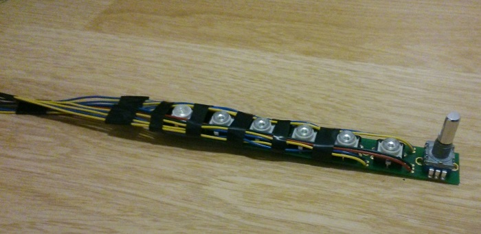
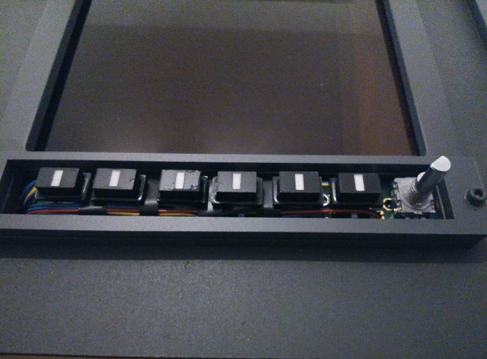
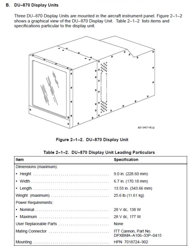
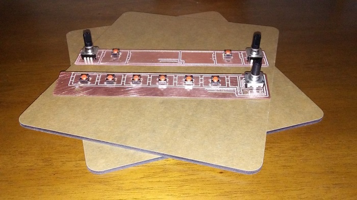
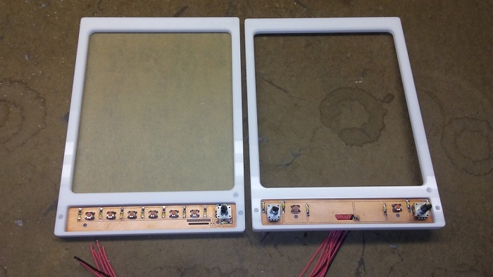
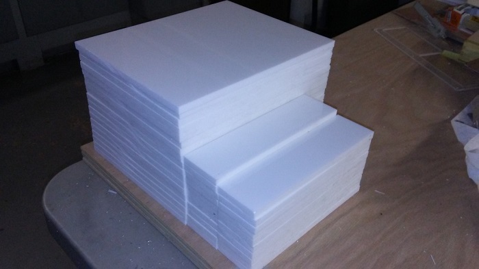
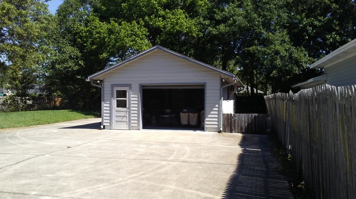
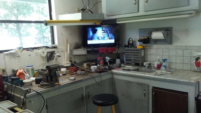
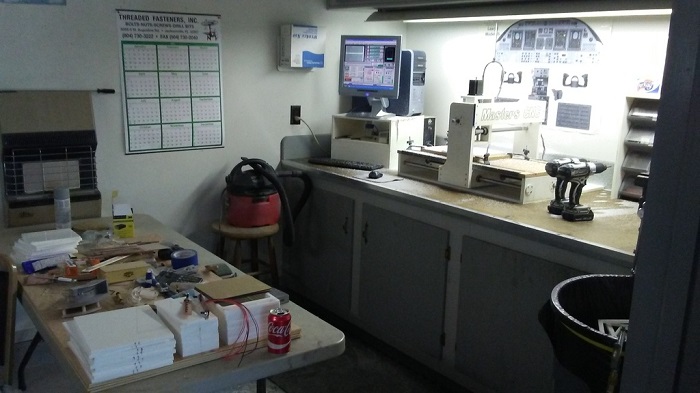
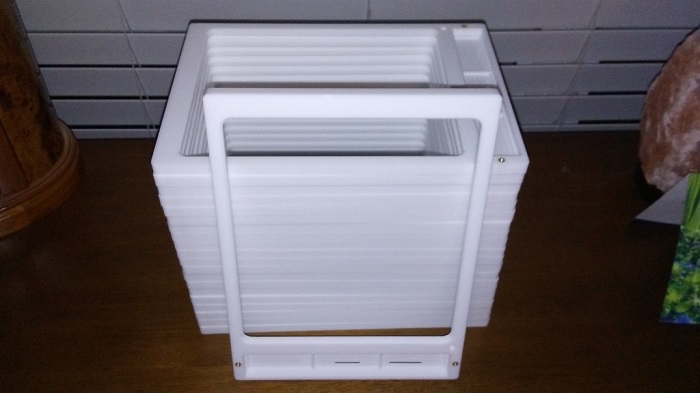
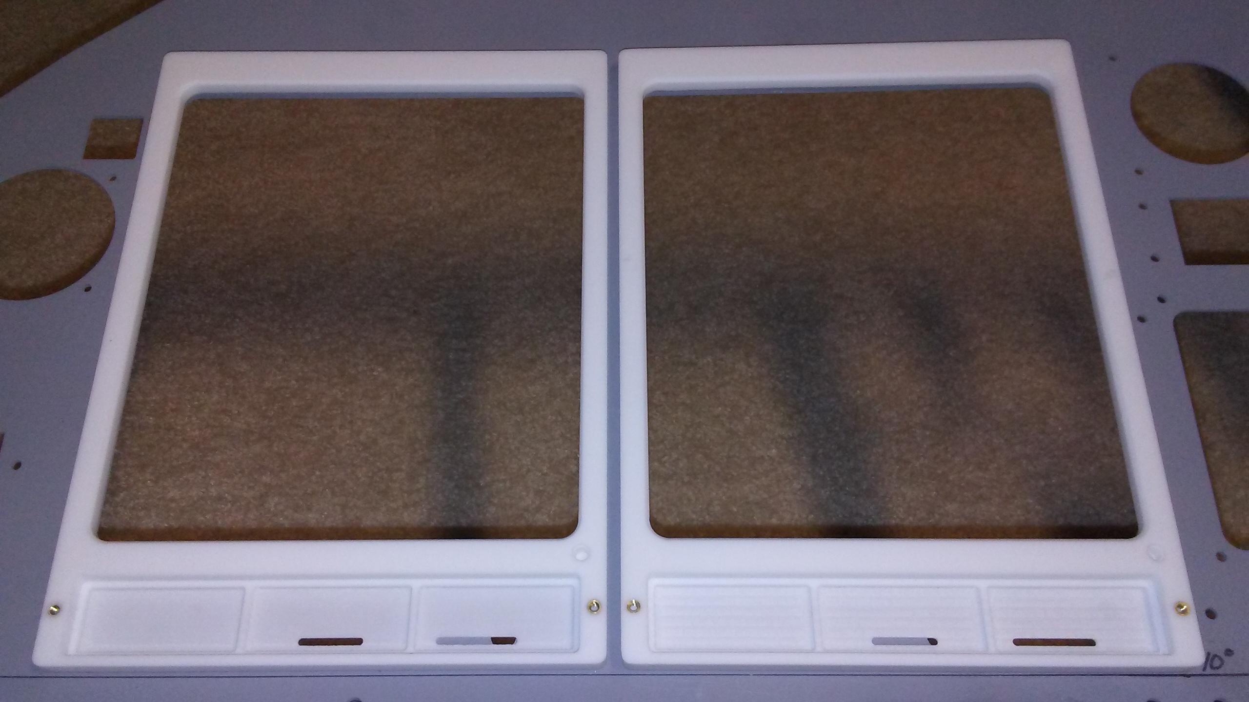
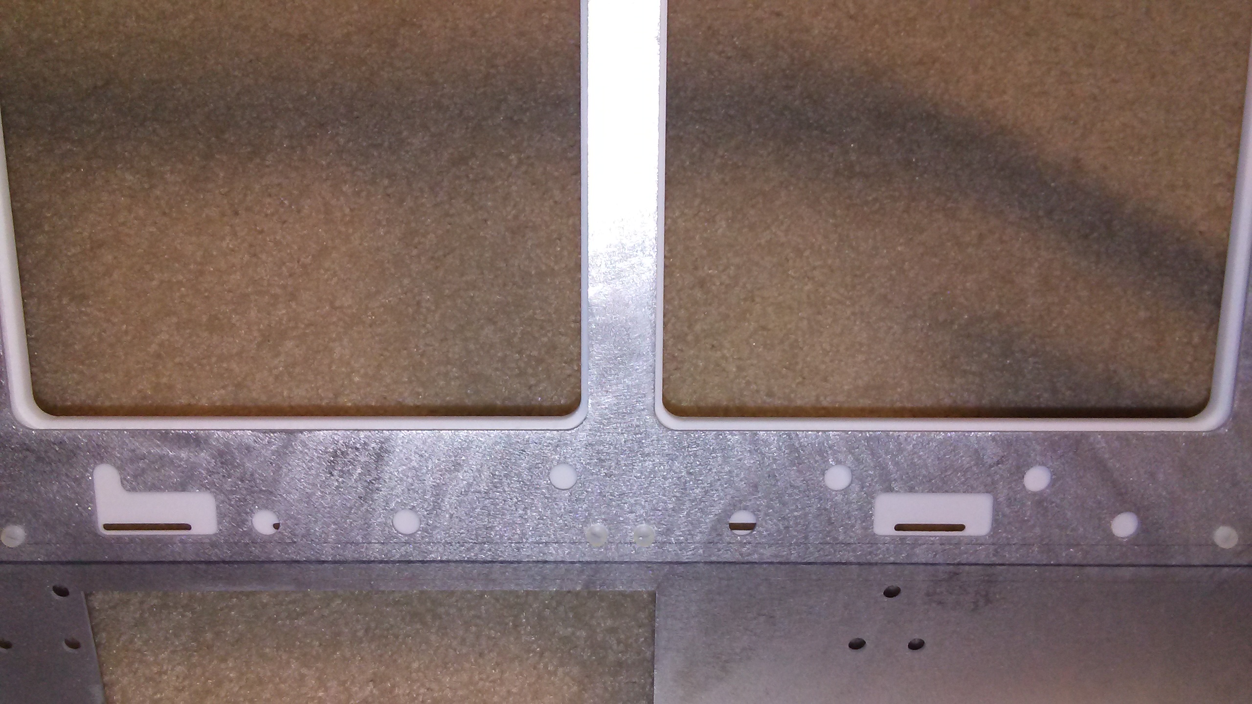
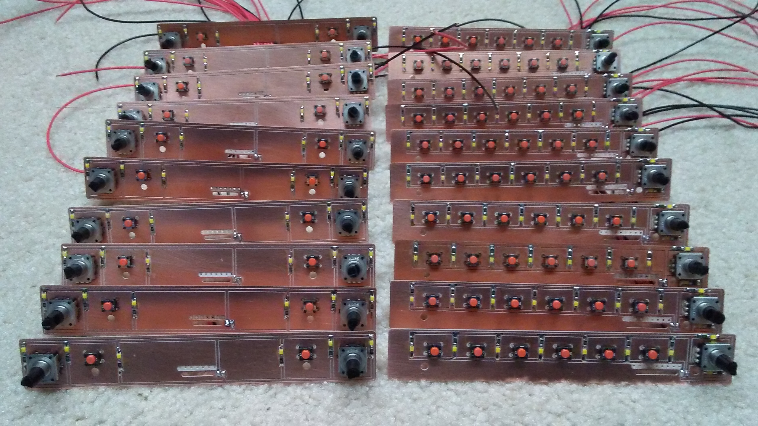
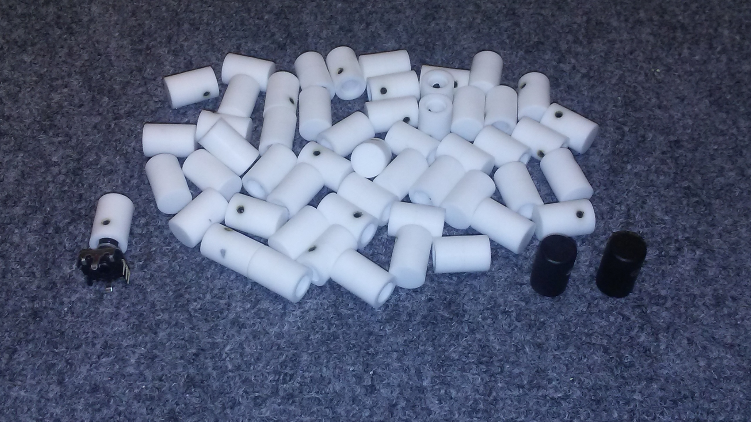
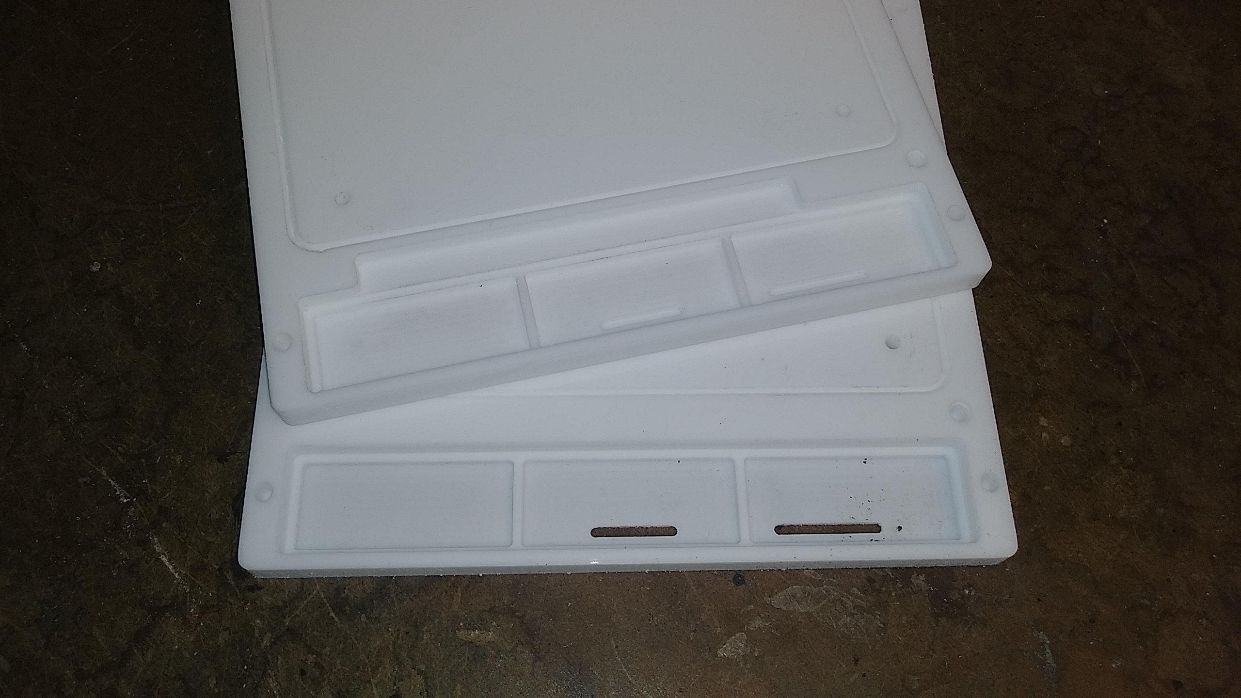
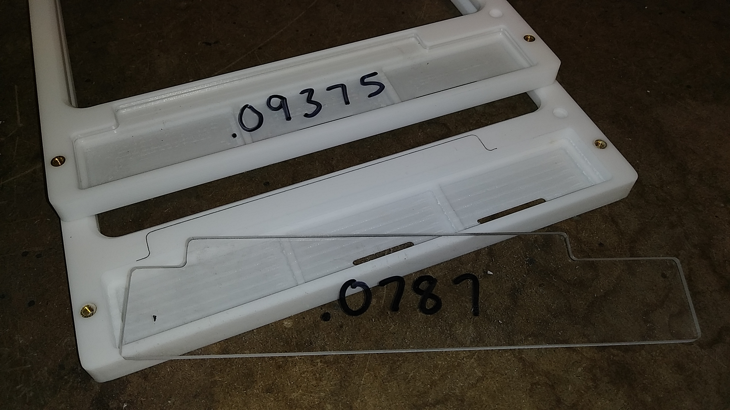
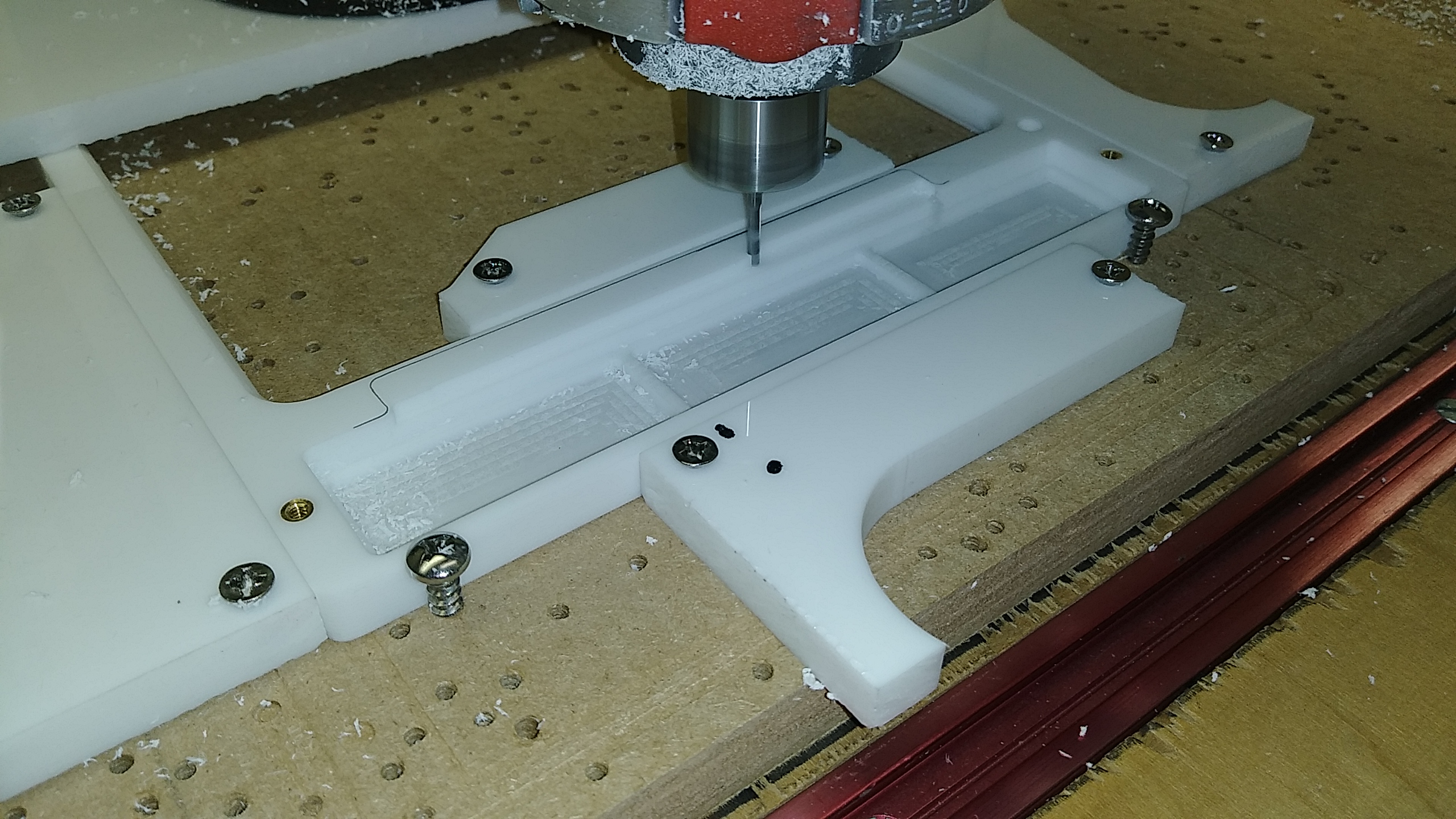
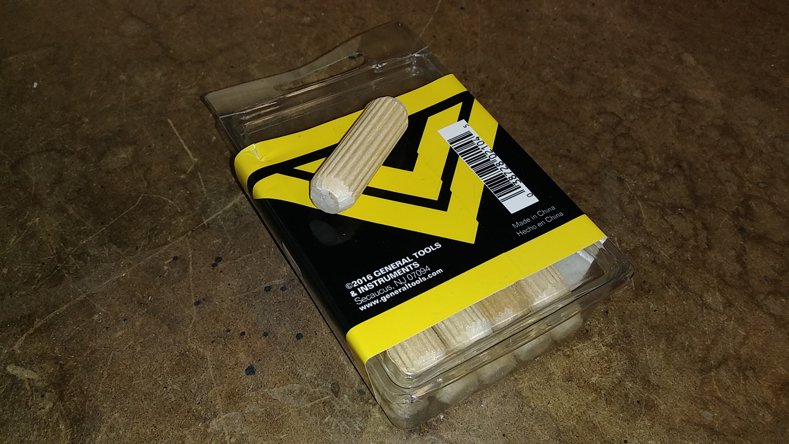
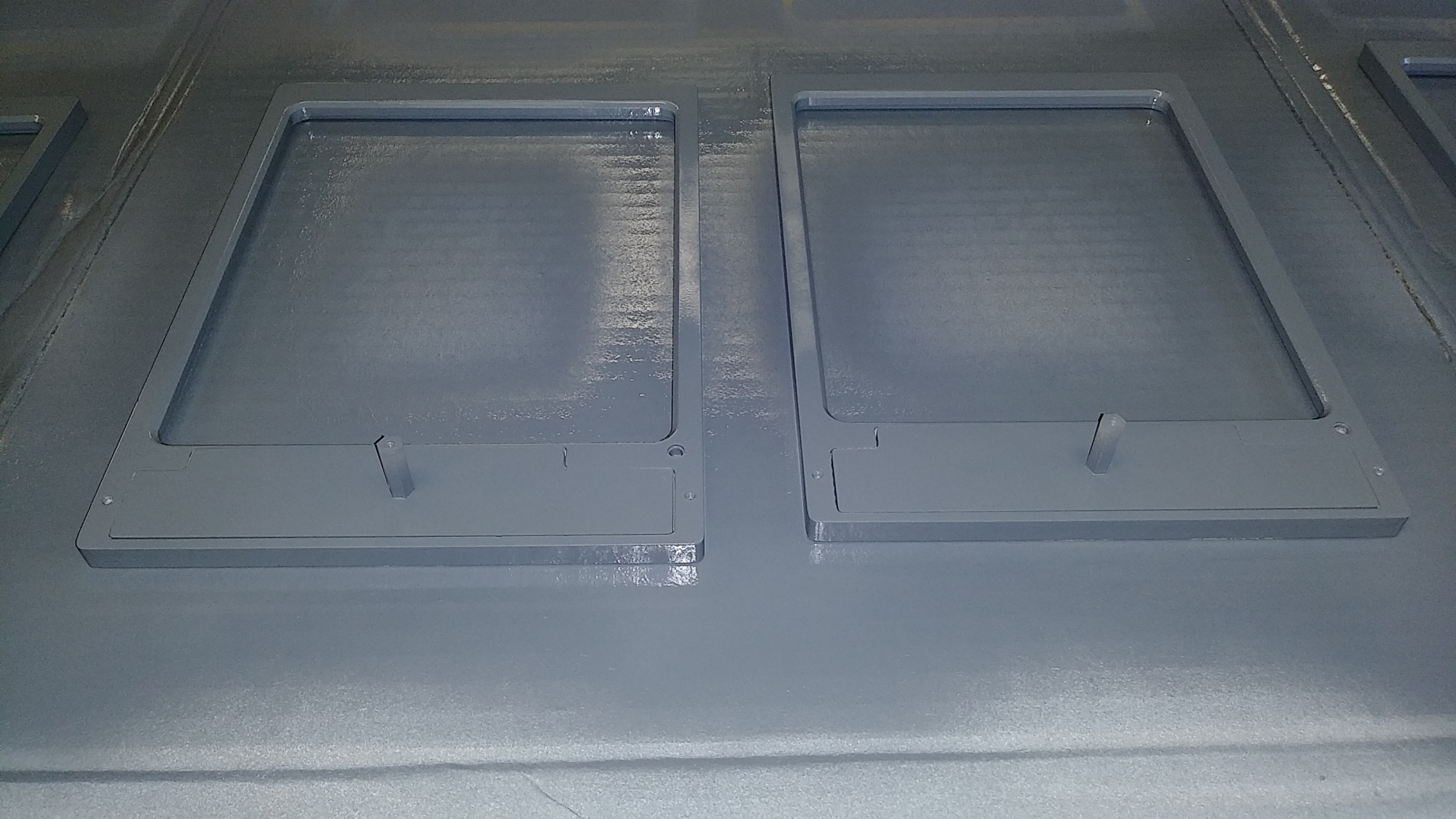
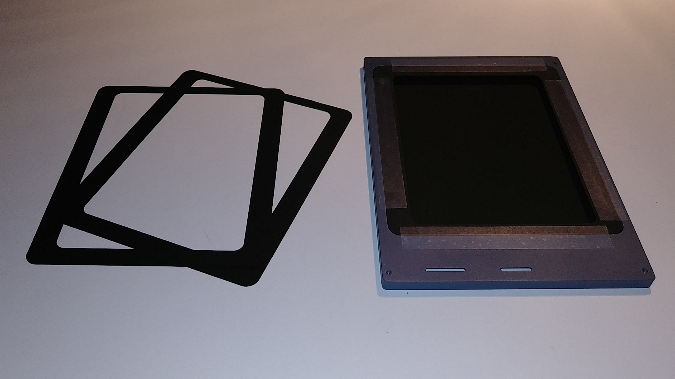
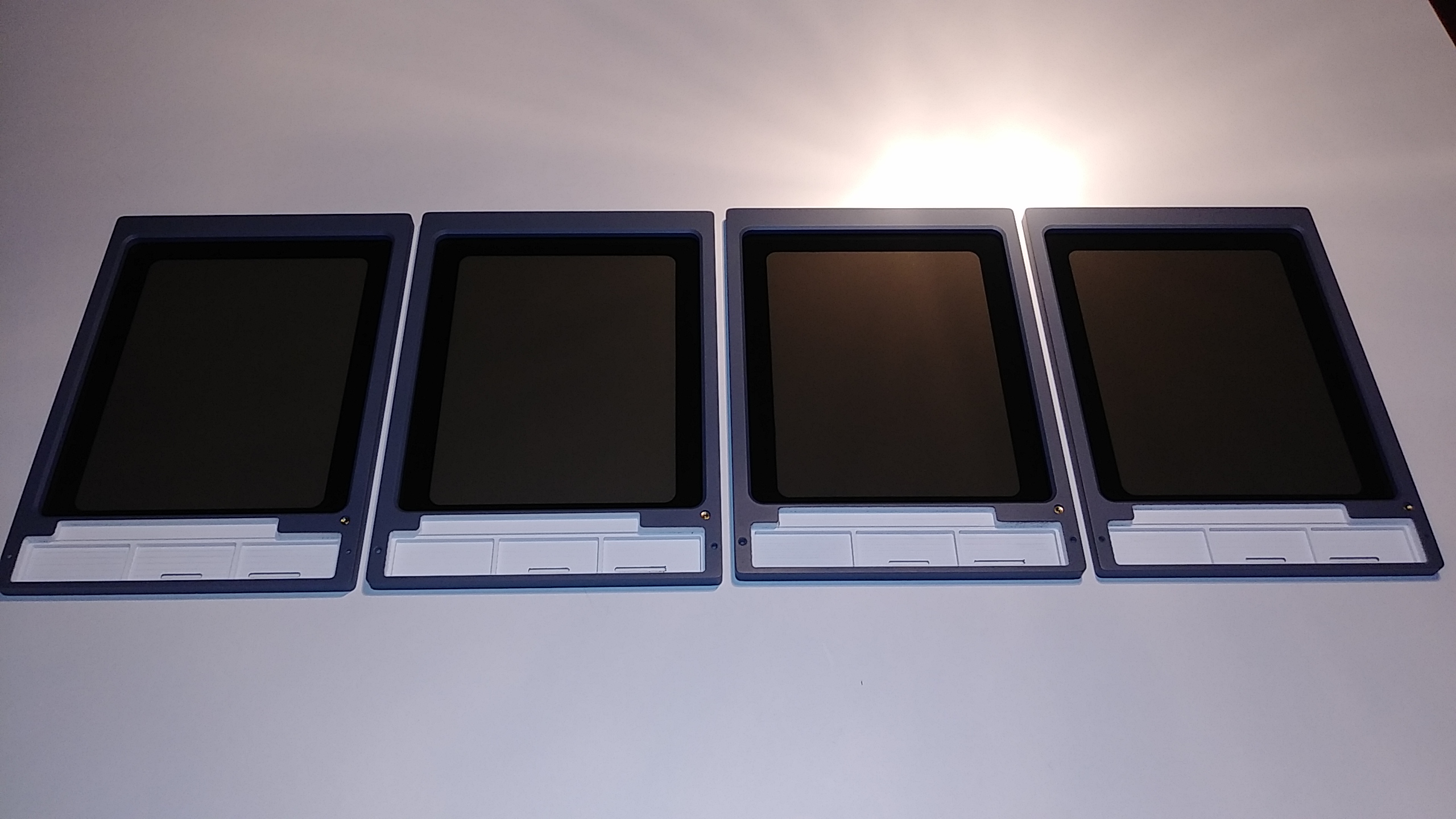
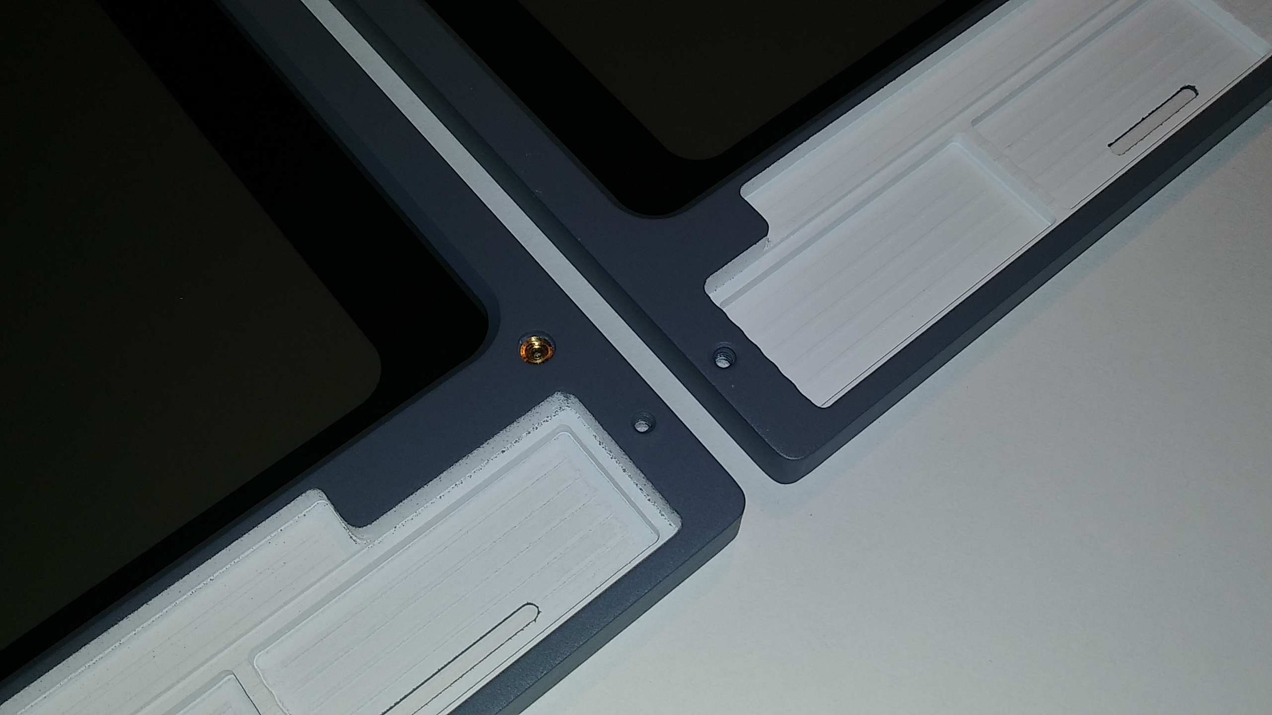
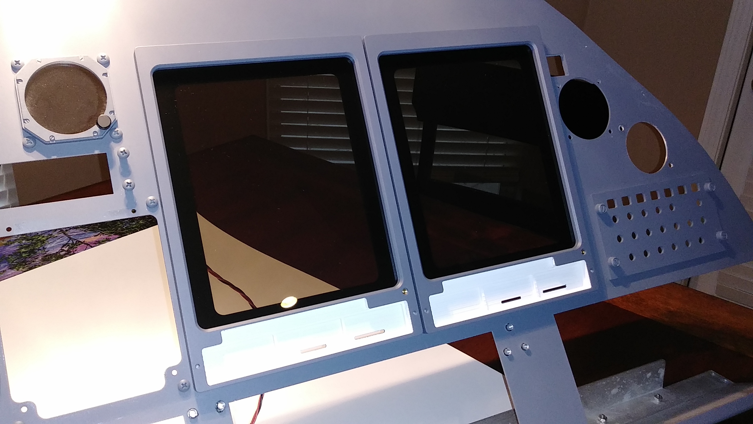
(Original thread started on 05-05-15 by Ron Rollo) Recently we have had a few request for the Display Units. I have always had them in future plans and I can now say they are on the drawing boards. (Actually in CAD) As many of you know, Vince took on the DUs and a few other key panels before he decided to leave the hobby/project. Between myself and Eric, we have been slowly developing the panels he was either working on or was planing on working on which included the FGC, EFIS panels, WX Radar panel and the Pitch Trim panel. I am happy to announce that next on the list are the DUs! I will be taking on most of the DU work because there is not a lot of front panel to be back lit and a lot more hardware/buttons to deal with. This will free up Eric to work on some of the remaining panels. (I know what he is going to be working on but I will let him announce that) So with all that said, let me tell you what to expect with the DUs. They will be designed to mount directly to the aluminum MIP with the LCD directly behind the MIP to provide the displays. This has always been a challenge because it limits us to design everything within the bezels which is about a half inch thick. No hardware will be allowed to protrude behind the aluminum MIP with the exception of the wires which will either be a flat ribbon cable or wires bound flat so that they will fit between the front of the LCD screen and the back side of the aluminum MIP. (Like some of us have now) The DUs will have a common ground and will be designed to be used with the Pokeys56U interface card. But because each one of the display units has less than eight inputs, they could be used with any of the FDS interface cards/InterfaceIT software. The encoders will more than likely be isolated to give you the option to use different interface cards if you wish. It will take me a few weeks to finish the drawings but I can at least say I have mapped out the trace lines and I do not see issues with why this can not be done! (Posted by Chris Capkalu on 05-12-15) Ron, good to hear! A little bit late for me as I build my DUs for myself some weeks ago. You are absolutely right about the challenging production due to the very limited space behind the MIP.Just to give you a short impression how I faced this challenge and the result. Keys are backlighting too. To all, THESE SHOTS ARE NOT THE UPCOMING DUs FROM RON! THESE ARE INDIVIDUAL ONES PRODUCED BY MYSELF FOR MY FLIGHTDECK: Wish you the best with this important next step! (Posted by Ron Rollo on 05-12-15) Thanks Chris, your DUs look really nice. I always like to see how others guys solve problems to get ideas. There is always more than one way to skin a cat. (Posted by Chris Capkalu on 06-03-15) When I read the comments about Vince' parts I am happy that my order never reached my house, additionally, he owes me around 100 Euro (prepayment) since he quit his shop. But I am totally satisfied that I build the DU frames for myself when I read about his product quality here with the RMU's. (Original thread started on 05-05-15 by Ron Rollo) Recently we have had a few request for the Display Units. I have always had them in future plans and I can now say they are on the drawing boards. (Actually in CAD) As many of you know, Vince took on the DUs and a few other key panels before he decided to leave the hobby/project. Between myself and Eric, we have been slowly developing the panels he was either working on or was planing on working on which included the FGC, EFIS panels, WX Radar panel and the Pitch Trim panel. I am happy to announce that next on the list are the DUs! I will be taking on most of the DU work because there is not a lot of front panel to be back lit and a lot more hardware/buttons to deal with. This will free up Eric to work on some of the remaining panels. (I know what he is going to be working on but I will let him announce that) So with all that said, let me tell you what to expect with the DUs. They will be designed to mount directly to the aluminum MIP with the LCD directly behind the MIP to provide the displays. This has always been a challenge because it limits us to design everything within the bezels which is about a half inch thick. No hardware will be allowed to protrude behind the aluminum MIP with the exception of the wires which will either be a flat ribbon cable or wires bound flat so that they will fit between the front of the LCD screen and the back side of the aluminum MIP. (Like some of us have now) The DUs will have a common ground and will be designed to be used with the Pokeys56U interface card. But because each one of the display units has less than eight inputs, they could be used with any of the FDS interface cards/InterfaceIT software. The encoders will more than likely be isolated to give you the option to use different interface cards if you wish. It will take me a few weeks to finish the drawings but I can at least say I have mapped out the trace lines and I do not see issues with why this can not be done! (Posted by Chris Capkalu on 05-12-15) Ron, good to hear! A little bit late for me as I build my DUs for myself some weeks ago. You are absolutely right about the challenging production due to the very limited space behind the MIP.Just to give you a short impression how I faced this challenge and the result. Keys are backlighting too. To all, THESE SHOTS ARE NOT THE UPCOMING DUs FROM RON! THESE ARE INDIVIDUAL ONES PRODUCED BY MYSELF FOR MY FLIGHTDECK: Wish you the best with this important next step! (Posted by Ron Rollo on 05-12-15) Thanks Chris, your DUs look really nice. I always like to see how others guys solve problems to get ideas. There is always more than one way to skin a cat. (Posted by Chris Capkalu on 06-03-15) When I read the comments about Vince' parts I am happy that my order never reached my house, additionally, he owes me around 100 Euro (prepayment) since he quit his shop. But I am totally satisfied that I build the DU frames for myself when I read about his product quality here with the RMU's. (Posted by Ron Rollo on 07-08-16) In the next few weeks I will start planning and drawing the DUs. Keep an eye out for them! (This document was provided by Will Sasse) UPDATE: Today I am officially starting work on the DUs. The first week or two will be in CAD and hunting down the correct hardware. They will be back lit and fully functional as you would expect. As soon as I get a couple prototype photos, I will post them up. My goal is to make delivery on the first batch (three or four sets) by April 2017. Keep in mind that a set consist of four display units. I will announce pricing once I have determined what it is going to take to make a set. Now is the time to let me know if you are interested in a set so I can start planning on material and hardware. So far I have Maciej, Jeff Peters and Jason Hite on the confirmed build list. Please post here or email me if you would like to get on the build list! Thanks guys for your patience on these. They will be worth the wait I promise! UPDATE: As of this date, 98% of the CAD work and planning is complete. So let me tell you a little bit about what you can expect in these display units that I have designed: 1. They are as close to scale as possible! Every effort has been put into this drawing to insure that the scale is correct. (I did not have to modify anything to make something work.) 2. They will mount perfectly to the MIP that I supply using nylon pan head screws form the back side. 3. All the buttons and encoders are operational. In other words, everything in the Jet45 AAS will be able to be accessed with these DUs. 4. The buttons and indicator lines including the circle around the encoder on DU 2 & 3 will be back lit. The design is durable and there will be no "hit and miss" like previous DUs. Additionally, every LED will have it's own resistor like every panel that I make. 5. The DUs are designed with one common ground and can be used with a Pokeys card, Arduino interface card or similar type interface cards. 6. The main body to all of the display units can be interchangeable. In other words, the PCB and lower front panels can be moved to fit onto any of the four backer frames. As far as pricing goes, I am aiming at around $700 to $800 for the set of four completely assembled. There are two things that the end user would need to do. First would be to mask the clear lenses to add the black boarder. Second would be to make the four wiring harness' to which ever interface card you choose. I can do these last two steps for you at an additional fee if you choose. I have ordered the plastic for several sets of DUs and the package should arrive in a few days. Next week I will start actually cutting out parts! The drawing are 99% complete. I just need to do a little more work on the button artwork, which there is not not much if you noticed. We are going to go with smoked gray lenses and the DUs will also include a laser cut lens bezel mask so that the end users do not have to tape off and paint the lenses. I am really excited to start cutting these parts to see what they are going to look like and operate! Again, if you are thinking about getting on board with these display units, now is the time to place an order with me. No money down for established Hangar45 members! (Posted by Maciej on 02-13-17) I'm just excited as you Ron! I got a set of your RMUs and I have no doubt that, just like an RMUs, your DUs are gonna be solid. Your work is second to none! (Posted by Shane Barnes on 02-14-17) Great news! Looking forward to upgrading the DU's. The smoke gray lenses will look great. I currently have the smoke grey installed on my DU's, they look great when battery/avionics are on and look correct when battery is off. (Posted by Ron Rollo on 07-08-16) In the next few weeks I will start planning and drawing the DUs. Keep an eye out for them! (This document was provided by Will Sasse) UPDATE: Today I am officially starting work on the DUs. The first week or two will be in CAD and hunting down the correct hardware. They will be back lit and fully functional as you would expect. As soon as I get a couple prototype photos, I will post them up. My goal is to make delivery on the first batch (three or four sets) by April 2017. Keep in mind that a set consist of four display units. I will announce pricing once I have determined what it is going to take to make a set. Now is the time to let me know if you are interested in a set so I can start planning on material and hardware. So far I have Maciej, Jeff Peters and Jason Hite on the confirmed build list. Please post here or email me if you would like to get on the build list! Thanks guys for your patience on these. They will be worth the wait I promise! UPDATE: As of this date, 98% of the CAD work and planning is complete. So let me tell you a little bit about what you can expect in these display units that I have designed: 1. They are as close to scale as possible! Every effort has been put into this drawing to insure that the scale is correct. (I did not have to modify anything to make something work.) 2. They will mount perfectly to the MIP that I supply using nylon pan head screws form the back side. 3. All the buttons and encoders are operational. In other words, everything in the Jet45 AAS will be able to be accessed with these DUs. 4. The buttons and indicator lines including the circle around the encoder on DU 2 & 3 will be back lit. The design is durable and there will be no "hit and miss" like previous DUs. Additionally, every LED will have it's own resistor like every panel that I make. 5. The DUs are designed with one common ground and can be used with a Pokeys card, Arduino interface card or similar type interface cards. 6. The main body to all of the display units can be interchangeable. In other words, the PCB and lower front panels can be moved to fit onto any of the four backer frames. As far as pricing goes, I am aiming at around $700 to $800 for the set of four completely assembled. There are two things that the end user would need to do. First would be to mask the clear lenses to add the black boarder. Second would be to make the four wiring harness' to which ever interface card you choose. I can do these last two steps for you at an additional fee if you choose. I have ordered the plastic for several sets of DUs and the package should arrive in a few days. Next week I will start actually cutting out parts! The drawing are 99% complete. I just need to do a little more work on the button artwork, which there is not not much if you noticed. We are going to go with smoked gray lenses and the DUs will also include a laser cut lens bezel mask so that the end users do not have to tape off and paint the lenses. I am really excited to start cutting these parts to see what they are going to look like and operate! Again, if you are thinking about getting on board with these display units, now is the time to place an order with me. No money down for established Hangar45 members! (Posted by Maciej on 02-13-17) I'm just excited as you Ron! I got a set of your RMUs and I have no doubt that, just like an RMUs, your DUs are gonna be solid. Your work is second to none! (Posted by Shane Barnes on 02-14-17) Great news! Looking forward to upgrading the DU's. The smoke gray lenses will look great. I currently have the smoke grey installed on my DU's, they look great when battery/avionics are on and look correct when battery is off. (Posted by Ron Rollo on 03-03-17) Another quick update on the Display Units. As you have probably read in another thread, my CNC blew a driver chip. My CNC was down for about 10 days and I have got a little behind on my DU work. The good news is the CNC is up and running and I have started cutting prototype parts. My hopes are that these prototype parts are perfect and I can call them production parts! Today I finalized the double sided clad files and have a few pieces cut out. I also have two smoked lenses cut. It's not much considering I had CNC issues to contend with: Additionally, all the hardware has arrived and I am ready to get to work! Next Thursday I will have a single day to work on finalizing the DU base frame and cut a few of them out. Keep an eye out for more updates! UPDATE: Sorry for the delay on any updates. I have been busy helping to work out solutions for the CDU/FMS. I will have some updates in another thread about that soon. As for the DUs, I have all the lenses cut out and I am ready to start cutting the backers for them. However, the CNC computer has gone south on me and I am in the process of replacing it. The good news is the CNC drivers have already been replaced so once I have a replacement computer, I should be good to go for a while. I have also completed testing of of the clad that holds all the switches and back lighting. All is good to go! I know it may seem like I have been a little quite lately but trust me, there is a lot of stuff getting done in the background. Keep an eye out for some photos of the new DUs soon! UPDATE: If it is not one thing it is another. Last week I had to spend a few days replacing my CNC computer. The good news is that the replacement computer is up and running, tested and everything is running better than ever. So after a few test cuts, I finally dialed in the CAM work for the display unit backers. Here are a few sneak peek photos: Here is the stack of plastic that I have to cut: Each of the larger pieces takes no less than one hour front and back with a couple tool changes. There are over 20 backers! The smaller pieces will take about an hour as well. So just these five sets that I am working on have 40 hours of CNC time, and that does not include the lenses, buttons or knobs. UPDATE: Here are a couple photos of the shop. Let me remind you that this is my father's workshop that is just three miles away from my house. So here is a quick tour around the workshop! It is a stand alone workshop with about 1100 square feet of space to work within. This is my dad's side of the workshop. A TV is a must to help keep us entertained especially when these large files are cutting: My side of the workshop with the CNC and work table: Other than the CNC machine, the tools that you will find in this workshop are every day tools that your would find in any workshop. As a matter of fact, I feel we are lacking a few things. One day I would like to get a lathe machine for turning certain items and the other tool would be a welding machine. One day.... UPDATE: I think it is safe to say that the CNC is back up and running better than ever. I just completed nearly 22 hours of CNC time over the past five days cutting out 21 DU backers front and back. On top of that, I never turned the computer off or closed down Mach3 in order to save X,Y, and Z settings. Everything worked great! Here is a photo of a stack of DU backers cut front and back. It may be a little difficult to see but they have a 45 degree bevel around the lens opening and there are six brass inserts pressed into each one. Four on the back side and two on the front side: Next will be to mass produce the double sided clad! The DU's are moving along nicely! (Posted by Ron Rollo on 03-03-17) Another quick update on the Display Units. As you have probably read in another thread, my CNC blew a driver chip. My CNC was down for about 10 days and I have got a little behind on my DU work. The good news is the CNC is up and running and I have started cutting prototype parts. My hopes are that these prototype parts are perfect and I can call them production parts! Today I finalized the double sided clad files and have a few pieces cut out. I also have two smoked lenses cut. It's not much considering I had CNC issues to contend with: Additionally, all the hardware has arrived and I am ready to get to work! Next Thursday I will have a single day to work on finalizing the DU base frame and cut a few of them out. Keep an eye out for more updates! UPDATE: Sorry for the delay on any updates. I have been busy helping to work out solutions for the CDU/FMS. I will have some updates in another thread about that soon. As for the DUs, I have all the lenses cut out and I am ready to start cutting the backers for them. However, the CNC computer has gone south on me and I am in the process of replacing it. The good news is the CNC drivers have already been replaced so once I have a replacement computer, I should be good to go for a while. I have also completed testing of of the clad that holds all the switches and back lighting. All is good to go! I know it may seem like I have been a little quite lately but trust me, there is a lot of stuff getting done in the background. Keep an eye out for some photos of the new DUs soon! UPDATE: If it is not one thing it is another. Last week I had to spend a few days replacing my CNC computer. The good news is that the replacement computer is up and running, tested and everything is running better than ever. So after a few test cuts, I finally dialed in the CAM work for the display unit backers. Here are a few sneak peek photos: Here is the stack of plastic that I have to cut: Each of the larger pieces takes no less than one hour front and back with a couple tool changes. There are over 20 backers! The smaller pieces will take about an hour as well. So just these five sets that I am working on have 40 hours of CNC time, and that does not include the lenses, buttons or knobs. UPDATE: Here are a couple photos of the shop. Let me remind you that this is my father's workshop that is just three miles away from my house. So here is a quick tour around the workshop! It is a stand alone workshop with about 1100 square feet of space to work within. This is my dad's side of the workshop. A TV is a must to help keep us entertained especially when these large files are cutting: My side of the workshop with the CNC and work table: Other than the CNC machine, the tools that you will find in this workshop are every day tools that your would find in any workshop. As a matter of fact, I feel we are lacking a few things. One day I would like to get a lathe machine for turning certain items and the other tool would be a welding machine. One day.... UPDATE: I think it is safe to say that the CNC is back up and running better than ever. I just completed nearly 22 hours of CNC time over the past five days cutting out 21 DU backers front and back. On top of that, I never turned the computer off or closed down Mach3 in order to save X,Y, and Z settings. Everything worked great! Here is a photo of a stack of DU backers cut front and back. It may be a little difficult to see but they have a 45 degree bevel around the lens opening and there are six brass inserts pressed into each one. Four on the back side and two on the front side: Next will be to mass produce the double sided clad! The DU's are moving along nicely! Hey guys, I am finally at a place where I can get back to work on the display units and other sim related projects. One of the things that I thought I was going to have to make was a template so that the guys who are getting a set of DUs could modify the MIP to accept the new DU design. Well, I guess it has been so long that I forgot that I worked all that into the design so that the DUs will simply screw onto the MIP without any modifications. Here is a photo of the pilot side DU's mounted to the MIP: (Right click to blow the photos up to full size!) You can see where the wires will be coming out of the two display units and passing through the MIP: Easy enough, no modification needed! Also, the display unit backers are universal meaning that one design can fit in either the DU1 and 4 position or the DU 2 and 3 position. More updates shortly. Hey guys, I am finally at a place where I can get back to work on the display units and other sim related projects. One of the things that I thought I was going to have to make was a template so that the guys who are getting a set of DUs could modify the MIP to accept the new DU design. Well, I guess it has been so long that I forgot that I worked all that into the design so that the DUs will simply screw onto the MIP without any modifications. Here is a photo of the pilot side DU's mounted to the MIP: (Right click to blow the photos up to full size!) You can see where the wires will be coming out of the two display units and passing through the MIP: Easy enough, no modification needed! Also, the display unit backers are universal meaning that one design can fit in either the DU1 and 4 position or the DU 2 and 3 position. More updates shortly. Nice work Ron! Looking forward to adding the Project45 DU's to my build! I see a major overhaul of my sim next year! All new Project45 RMU'S and DU'S and hopefully the addition of Randy's rudder pedals! Nice work Ron! Looking forward to adding the Project45 DU's to my build! I see a major overhaul of my sim next year! All new Project45 RMU'S and DU'S and hopefully the addition of Randy's rudder pedals! Another quick update on the Display Units. I have just completed the PCBs and their components for all five sets. If you blow the photo up by right clicking on it you can see the tiny LEDs and the resistors too. Talk about a lot of tedious soldering! Now that I have these done I can move on to the lower front cover plates which are going to be fun. I have them drawn out but it is another piece that will require front and back milling with the CNC. More updates soon! Another quick update on the Display Units. I have just completed the PCBs and their components for all five sets. If you blow the photo up by right clicking on it you can see the tiny LEDs and the resistors too. Talk about a lot of tedious soldering! Now that I have these done I can move on to the lower front cover plates which are going to be fun. I have them drawn out but it is another piece that will require front and back milling with the CNC. More updates soon! Those are looking good! Looking forward to seeing the completed unit ... and adding them to my build! Those are looking good! Looking forward to seeing the completed unit ... and adding them to my build! Quick update. I got the knobs finished for seven sets of Display Units. Keep in mind that there are four DUs in each set! As I am moving forward with almost everything that I am doing, I am trying to make a few extra set of things to eventually get to the point where if someone wants something, we will be able to supply it in a timely manor. So in other words, two of these knob sets are not spoken for yet. Unlike previous knob sets from past suppliers, these knobs will come with the set screws already in place. One less thing the end user has to worry about. More updates soon! Quick update. I got the knobs finished for seven sets of Display Units. Keep in mind that there are four DUs in each set! As I am moving forward with almost everything that I am doing, I am trying to make a few extra set of things to eventually get to the point where if someone wants something, we will be able to supply it in a timely manor. So in other words, two of these knob sets are not spoken for yet. Unlike previous knob sets from past suppliers, these knobs will come with the set screws already in place. One less thing the end user has to worry about. More updates soon! Hey guys, I apologize for not updating this thread sooner. I got side tracked with higher priority sim issues, mostly to do with the TQ modules, the FGC and redrawing every panel in the Lear45 sim! I felt before we could move forward, we all needed a solid foundation to stand on and we are almost there. Eight sets of the Display Units will be completed no later than Christmas AND, all the DXF drawing for anything you can imagine to do with the Lear45 sim build will be available in the Builder Resources page on JAN 1st 2020! So keep an eye out for that. Now that I have my plate cleaned a little, I can focus more on the Display Units. I have actually been working on them for at least the past four weeks and have been privately updating those of you who are on the build list. If you are one of those guys that like what you see, you can either get on the build list for the second batch or, if you have a CNC, you will be able to make your own with the drawings and G code that will be available soon. I will say this, if you are new to CNC work, the Display Units are not a good place to start because of the complexity of multiple cuts on several pieces front and back. However, with a little CNC skills, every panel and part in the Lear45 can be made to a high degree of satisfaction! So let me get you caught up with where we are at this moment. Initially I started making five sets of Display Units and I got to a point that I was about 70% complete with them. But now I have added three more sets and have got them caught up to the first five sets. Keep in mind that there are four Display Units in each set so I am working on no less than thirty two individual Display Units which every piece has to be cut front and back! So you can quickly see how fast making just a couple sets can slow things down. Long story short, after four weeks I am still just 70% complete! Along the way I have discovered several places where I could improve on the design of the DUs. The first being what I call the backlight pocket. There are several hash lines on DU's 2 and 3 that need as much help as possible to get them to illuminate. So extending the backlight pocket up a little higher will help with that. Additionally, in order to keep the DU backers uniform and interchangeable with each other, I went ahead and made the changes on both types of DUs. In other words, all the DUs are still going to be interchangeable. In this photo below, the DU backer on top has been properly cut with the additional backlight chamber. The one on the bottom still needs to be updated: (As always, right click on photo to maximize using Firefox) This photo shows the template jigs to properly mark the earlier DU backers with the update: Last but not least, the DU part is secured in a placement jig and the cuts are controlled manually: I think it is important to share some of the "behind the since" details with everyone, especially those who want to try to make some panels on their own. Sometimes we have to make some manual cuts if they are easy enough to maneuver. If the cuts were anymore complicated, I would have to scrap the part and let the G code make a whole new piece. In this case, I had around 25 pieces to save! They all turned out perfect by the way. Another area that I wanted to revisit before I got too much further down the road was the knobs. The real Display Knobs look so simple and you would think that they are all over the internet and available. Well, after looking at thousands of knobs and using multiple search terms, I was unable to come up with an easy and cheap solution. There were a few that were close, for $2 a piece, but still not close enough. So I went to the Learjet Super Store (Home Depot) and found these: They are .5" Birch wooden furniture dowels. They are the right diameter and can be cut down to the correct height which I believe is .75". They have the splines or if you prefer to call them grooves or channels which is the look and feel I was looking for. If you do want to try to work with these on your own, two things to keep in mind. First, wrap them in blue painter's tape. This will keep them from splintering up when cutting. The second thing is be SUPER careful when cutting! So after wrapping with tape, cutting the first ends off and then the second ends leaving exactly .75", I made the holes for the set screws. Then I made a quick G code file that created a six piece jig that I could press the "would be knobs" into and let the CNC make the final inside cut for the encoder shaft. This method insures that the hole is perfectly centered. AND, it was important to have the set screw holes done before the final encoder hole because most of them required running a 22 gauge wire through that hole in order to pull the knobs out of their jig holes! This is what I have so far: At this point I have not yet sanded them or put the small 45 degree beveled edge on the top and bottom of the knobs. I think these are going to be a nice solution to the real Honeywell Display knobs that we can not yet find. If nothing else, these knobs will make an excellent temporary knob while we continue to wait for a better option to show itself! The last BIG update that I wanted to catch you up on is that Jason Hite is working on a new and improved way to interface all of the Jet45 modules with the sim using Arduino cards. So far he has successfully interfaced the RMUs, CDU/FMS and the FGC using Arduino interface cards. Every avionics module including the Display Units and EFIS panels will be interfaced using Ardunio cards. To date, I have created several Arduino Interface boards to help with wire management so that we have a nice clean looking sim. In the next few days I will be creating a couple prototype Ardunio interface boards for the Display Units and the EFIS panels. We will have more on this as it all develops so keep an eye out! Hey guys, I apologize for not updating this thread sooner. I got side tracked with higher priority sim issues, mostly to do with the TQ modules, the FGC and redrawing every panel in the Lear45 sim! I felt before we could move forward, we all needed a solid foundation to stand on and we are almost there. Eight sets of the Display Units will be completed no later than Christmas AND, all the DXF drawing for anything you can imagine to do with the Lear45 sim build will be available in the Builder Resources page on JAN 1st 2020! So keep an eye out for that. Now that I have my plate cleaned a little, I can focus more on the Display Units. I have actually been working on them for at least the past four weeks and have been privately updating those of you who are on the build list. If you are one of those guys that like what you see, you can either get on the build list for the second batch or, if you have a CNC, you will be able to make your own with the drawings and G code that will be available soon. I will say this, if you are new to CNC work, the Display Units are not a good place to start because of the complexity of multiple cuts on several pieces front and back. However, with a little CNC skills, every panel and part in the Lear45 can be made to a high degree of satisfaction! So let me get you caught up with where we are at this moment. Initially I started making five sets of Display Units and I got to a point that I was about 70% complete with them. But now I have added three more sets and have got them caught up to the first five sets. Keep in mind that there are four Display Units in each set so I am working on no less than thirty two individual Display Units which every piece has to be cut front and back! So you can quickly see how fast making just a couple sets can slow things down. Long story short, after four weeks I am still just 70% complete! Along the way I have discovered several places where I could improve on the design of the DUs. The first being what I call the backlight pocket. There are several hash lines on DU's 2 and 3 that need as much help as possible to get them to illuminate. So extending the backlight pocket up a little higher will help with that. Additionally, in order to keep the DU backers uniform and interchangeable with each other, I went ahead and made the changes on both types of DUs. In other words, all the DUs are still going to be interchangeable. In this photo below, the DU backer on top has been properly cut with the additional backlight chamber. The one on the bottom still needs to be updated: (As always, right click on photo to maximize using Firefox) This photo shows the template jigs to properly mark the earlier DU backers with the update: Last but not least, the DU part is secured in a placement jig and the cuts are controlled manually: I think it is important to share some of the "behind the since" details with everyone, especially those who want to try to make some panels on their own. Sometimes we have to make some manual cuts if they are easy enough to maneuver. If the cuts were anymore complicated, I would have to scrap the part and let the G code make a whole new piece. In this case, I had around 25 pieces to save! They all turned out perfect by the way. Another area that I wanted to revisit before I got too much further down the road was the knobs. The real Display Knobs look so simple and you would think that they are all over the internet and available. Well, after looking at thousands of knobs and using multiple search terms, I was unable to come up with an easy and cheap solution. There were a few that were close, for $2 a piece, but still not close enough. So I went to the Learjet Super Store (Home Depot) and found these: They are .5" Birch wooden furniture dowels. They are the right diameter and can be cut down to the correct height which I believe is .75". They have the splines or if you prefer to call them grooves or channels which is the look and feel I was looking for. If you do want to try to work with these on your own, two things to keep in mind. First, wrap them in blue painter's tape. This will keep them from splintering up when cutting. The second thing is be SUPER careful when cutting! So after wrapping with tape, cutting the first ends off and then the second ends leaving exactly .75", I made the holes for the set screws. Then I made a quick G code file that created a six piece jig that I could press the "would be knobs" into and let the CNC make the final inside cut for the encoder shaft. This method insures that the hole is perfectly centered. AND, it was important to have the set screw holes done before the final encoder hole because most of them required running a 22 gauge wire through that hole in order to pull the knobs out of their jig holes! This is what I have so far: At this point I have not yet sanded them or put the small 45 degree beveled edge on the top and bottom of the knobs. I think these are going to be a nice solution to the real Honeywell Display knobs that we can not yet find. If nothing else, these knobs will make an excellent temporary knob while we continue to wait for a better option to show itself! The last BIG update that I wanted to catch you up on is that Jason Hite is working on a new and improved way to interface all of the Jet45 modules with the sim using Arduino cards. So far he has successfully interfaced the RMUs, CDU/FMS and the FGC using Arduino interface cards. Every avionics module including the Display Units and EFIS panels will be interfaced using Ardunio cards. To date, I have created several Arduino Interface boards to help with wire management so that we have a nice clean looking sim. In the next few days I will be creating a couple prototype Ardunio interface boards for the Display Units and the EFIS panels. We will have more on this as it all develops so keep an eye out! Progress on the Display Units is heading in the right direction and there are so many areas to get you caught up on! First, the wooden knobs turned out really well, although time consuming. I am going to continue to keep my eyes open for those elusive Honeywell knobs! In the meantime, we have a coupe replica options, see photo: I made up a complete set of Display Unit Sub Modules and a couple RMU Sub Modules for Jason to do some testing. What we are trying to achieve here is a true "plug and play" solution using Ardunio Nanos and Mega interface cards. Here are a couple photos: I have since sent these onto Jason and we discovered that I needed to make a few changes and the second set is in the mail! Nothing is ever easy with this project and as I said to Jason, I had it in my time budget to make them at least twice! The DU paint plugs turned out very nice and have since served their purpose well: Simply pop them in the light pocket, paint and pop out after the paint dries! I also got the DU screen mask back from the laser shop. They are made of thick construction paper like 1st graders play with in art class. The laser did a great job cutting these pieces out with crisp and clean edges! In the photo below, the smoked lens is in place and the screen mask is held in place with Scottish tape! Here is a group of four just waiting for the lower front plate and some bottoms. (Aren't we all!) I took some time to add a little "Eye Candy" for guys like myself and Shane Barnes. I have no idea what it is for, maybe some sort of test port, DonnyRay would know. I used a 4-40 brass inset and then painted some 4-40 hex set screws gold. The look is authentic! (Right click to enlarge) Last but not least, here is a photo of a couple DUs mounted to a MIP. Pretty sweet! I know it is taking some time but everyone on the list to receive a set will truly appreciate all the effort and work! Now that I have the chores of the DUs just about behind me, I am free and clear to move forward with the lower front plates and some buttons! Keep an eye out on this thread, it's getting hot! Progress on the Display Units is heading in the right direction and there are so many areas to get you caught up on! First, the wooden knobs turned out really well, although time consuming. I am going to continue to keep my eyes open for those elusive Honeywell knobs! In the meantime, we have a coupe replica options, see photo: I made up a complete set of Display Unit Sub Modules and a couple RMU Sub Modules for Jason to do some testing. What we are trying to achieve here is a true "plug and play" solution using Ardunio Nanos and Mega interface cards. Here are a couple photos: I have since sent these onto Jason and we discovered that I needed to make a few changes and the second set is in the mail! Nothing is ever easy with this project and as I said to Jason, I had it in my time budget to make them at least twice! The DU paint plugs turned out very nice and have since served their purpose well: Simply pop them in the light pocket, paint and pop out after the paint dries! I also got the DU screen mask back from the laser shop. They are made of thick construction paper like 1st graders play with in art class. The laser did a great job cutting these pieces out with crisp and clean edges! In the photo below, the smoked lens is in place and the screen mask is held in place with Scottish tape! Here is a group of four just waiting for the lower front plate and some bottoms. (Aren't we all!) I took some time to add a little "Eye Candy" for guys like myself and Shane Barnes. I have no idea what it is for, maybe some sort of test port, DonnyRay would know. I used a 4-40 brass inset and then painted some 4-40 hex set screws gold. The look is authentic! (Right click to enlarge) Last but not least, here is a photo of a couple DUs mounted to a MIP. Pretty sweet! I know it is taking some time but everyone on the list to receive a set will truly appreciate all the effort and work! Now that I have the chores of the DUs just about behind me, I am free and clear to move forward with the lower front plates and some buttons! Keep an eye out on this thread, it's getting hot! Display Unit Development by Project45
![]()
![]()
![]()
![]()
![]()
![]()
![]()
![]()
![]()
![]()

Forum NavigationDisplay Unit Development by Project45
![]() #1 · December 14, 2017, 12:49 pm
#1 · December 14, 2017, 12:49 pm![]() #2 · January 4, 2018, 12:19 pmRon Rollo has reacted to this post.Ron Rollo
#2 · January 4, 2018, 12:19 pmRon Rollo has reacted to this post.Ron Rollo![]() #3 · January 4, 2018, 12:37 pmRon Rollo has reacted to this post.Ron Rollo
#3 · January 4, 2018, 12:37 pmRon Rollo has reacted to this post.Ron Rollo![]() #4 · February 19, 2018, 9:57 amRon Rollo, Shane Barnes and groof have reacted to this post.Ron RolloShane Barnesgroof
#4 · February 19, 2018, 9:57 amRon Rollo, Shane Barnes and groof have reacted to this post.Ron RolloShane Barnesgroof![]() #5 · February 19, 2018, 12:18 pm
#5 · February 19, 2018, 12:18 pm![]() #6 · March 15, 2018, 12:33 pmShane Barnes has reacted to this post.Shane Barnes
#6 · March 15, 2018, 12:33 pmShane Barnes has reacted to this post.Shane Barnes![]() #7 · March 15, 2018, 8:20 pm
#7 · March 15, 2018, 8:20 pm![]() #8 · May 1, 2018, 7:59 am
#8 · May 1, 2018, 7:59 am![]() #9 · September 16, 2019, 7:42 am
#9 · September 16, 2019, 7:42 am![]() #10 · September 27, 2019, 11:42 am
#10 · September 27, 2019, 11:42 am
2017-10-10