


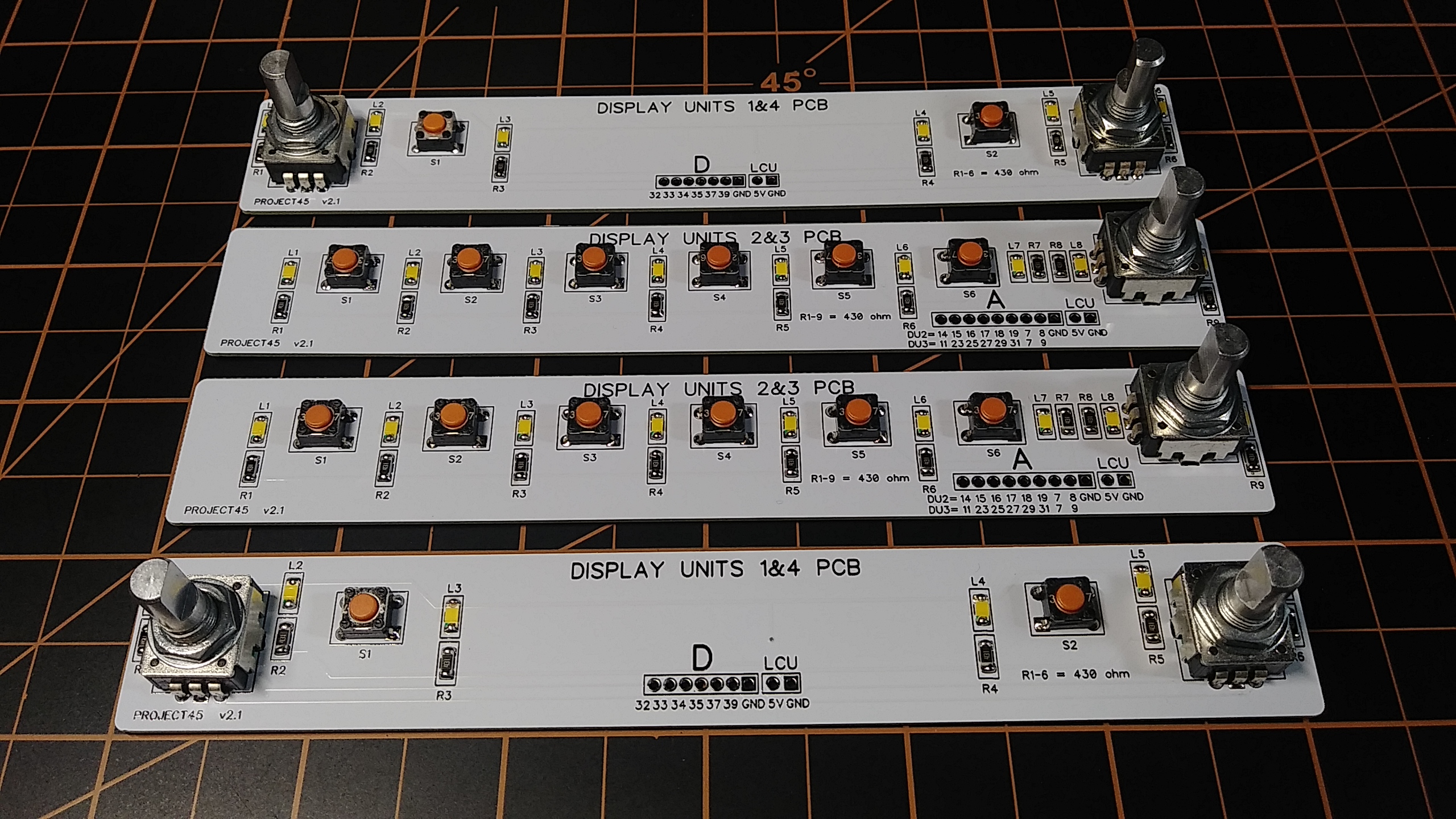
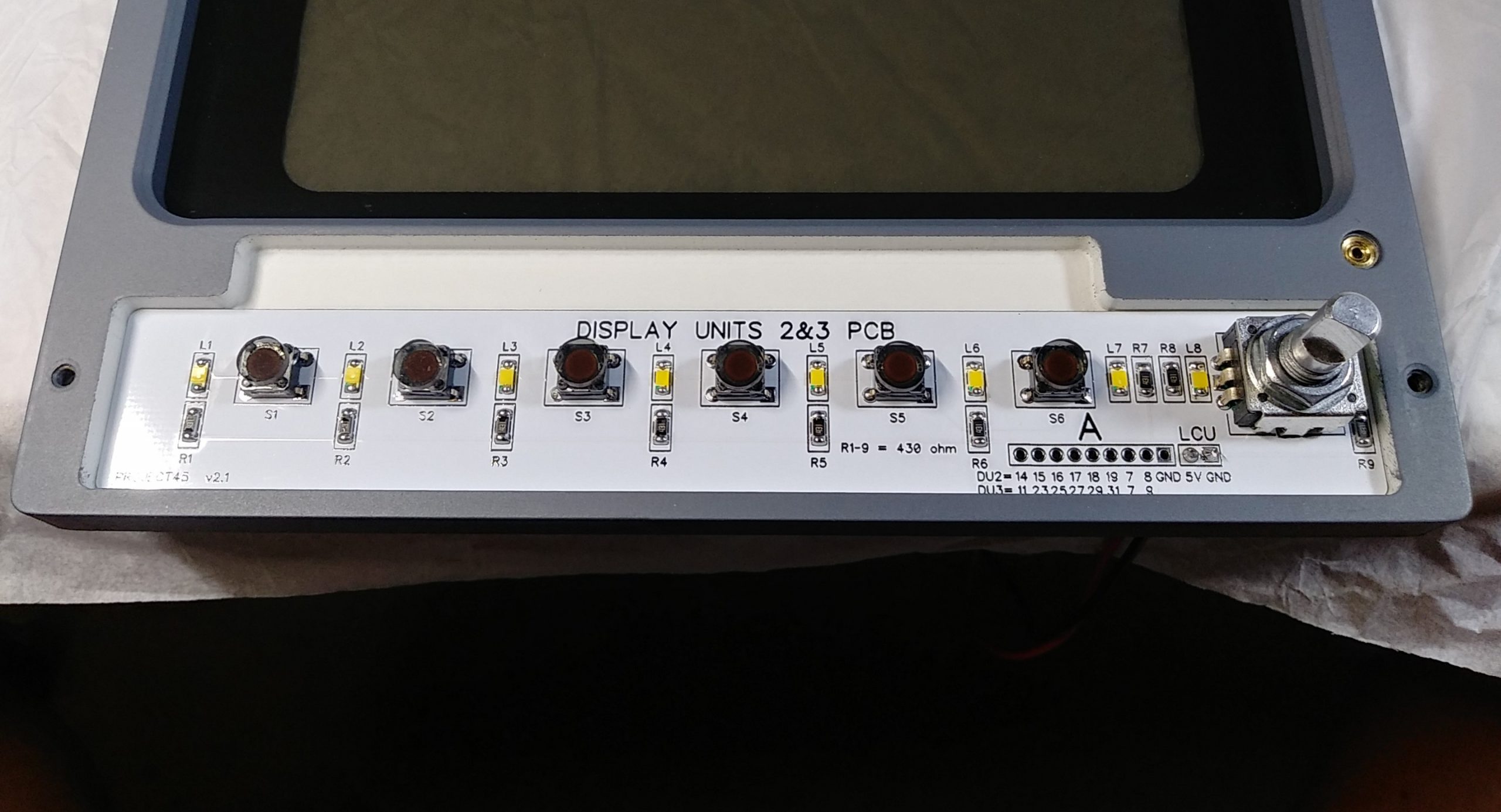
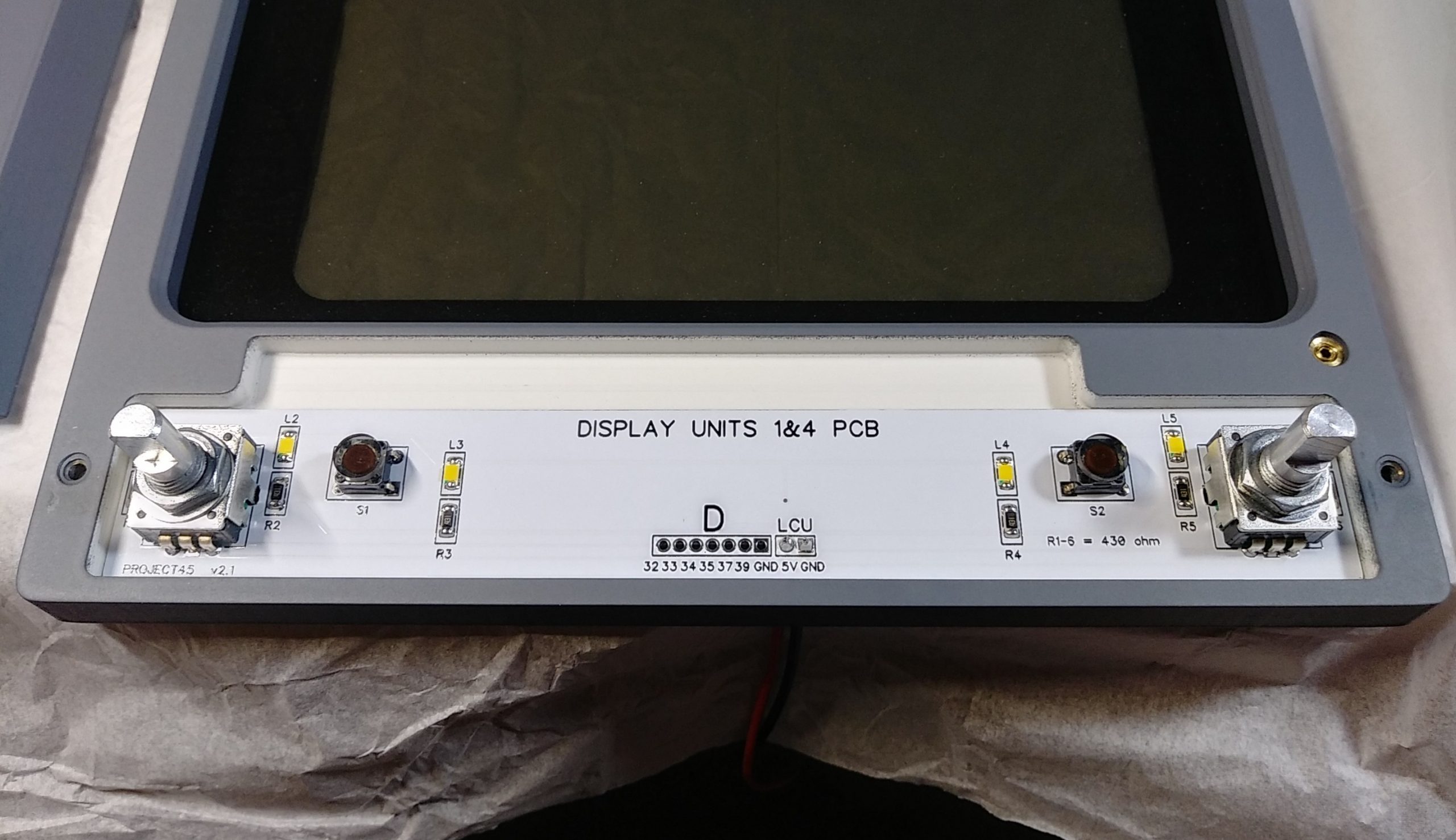
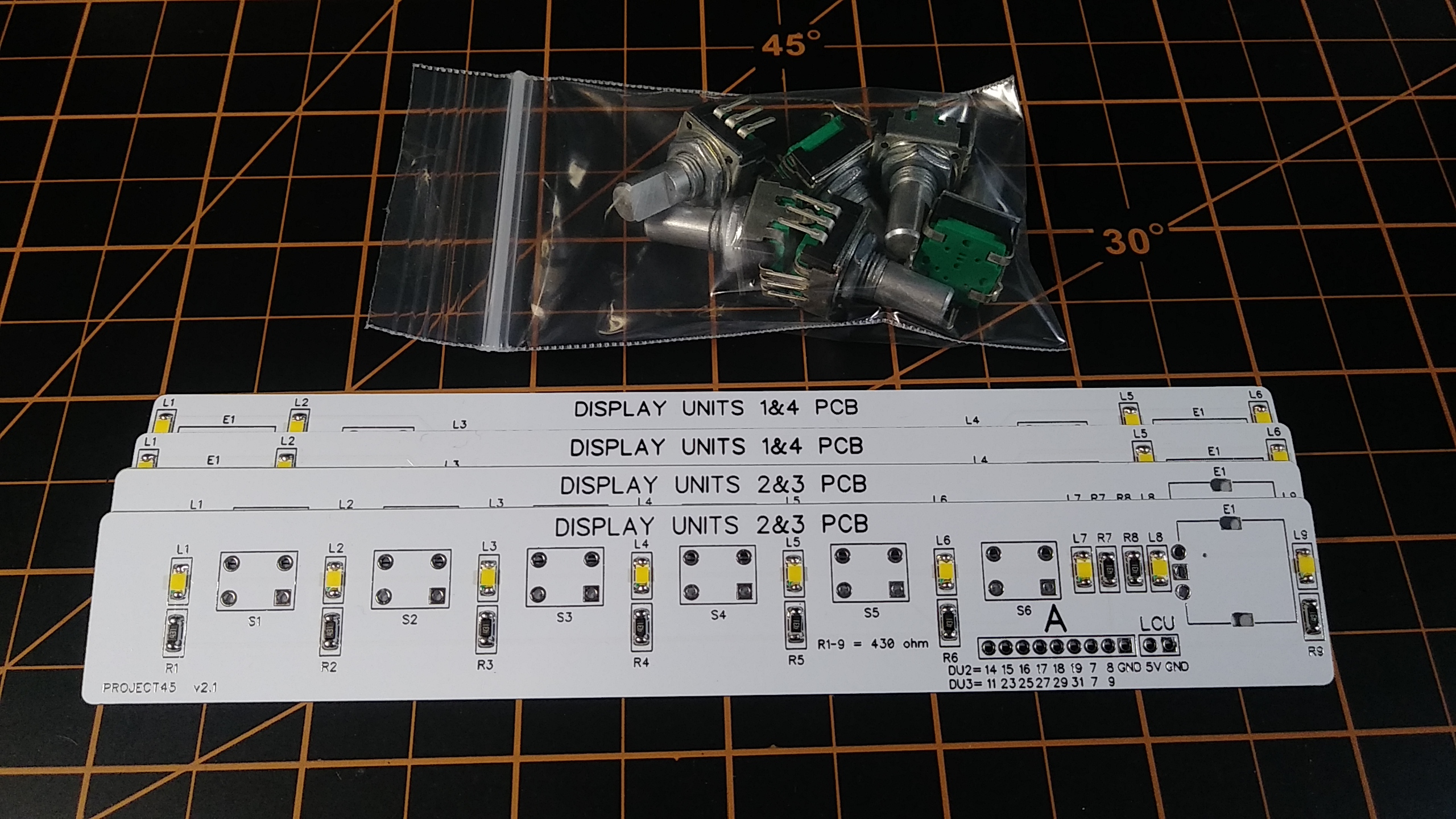
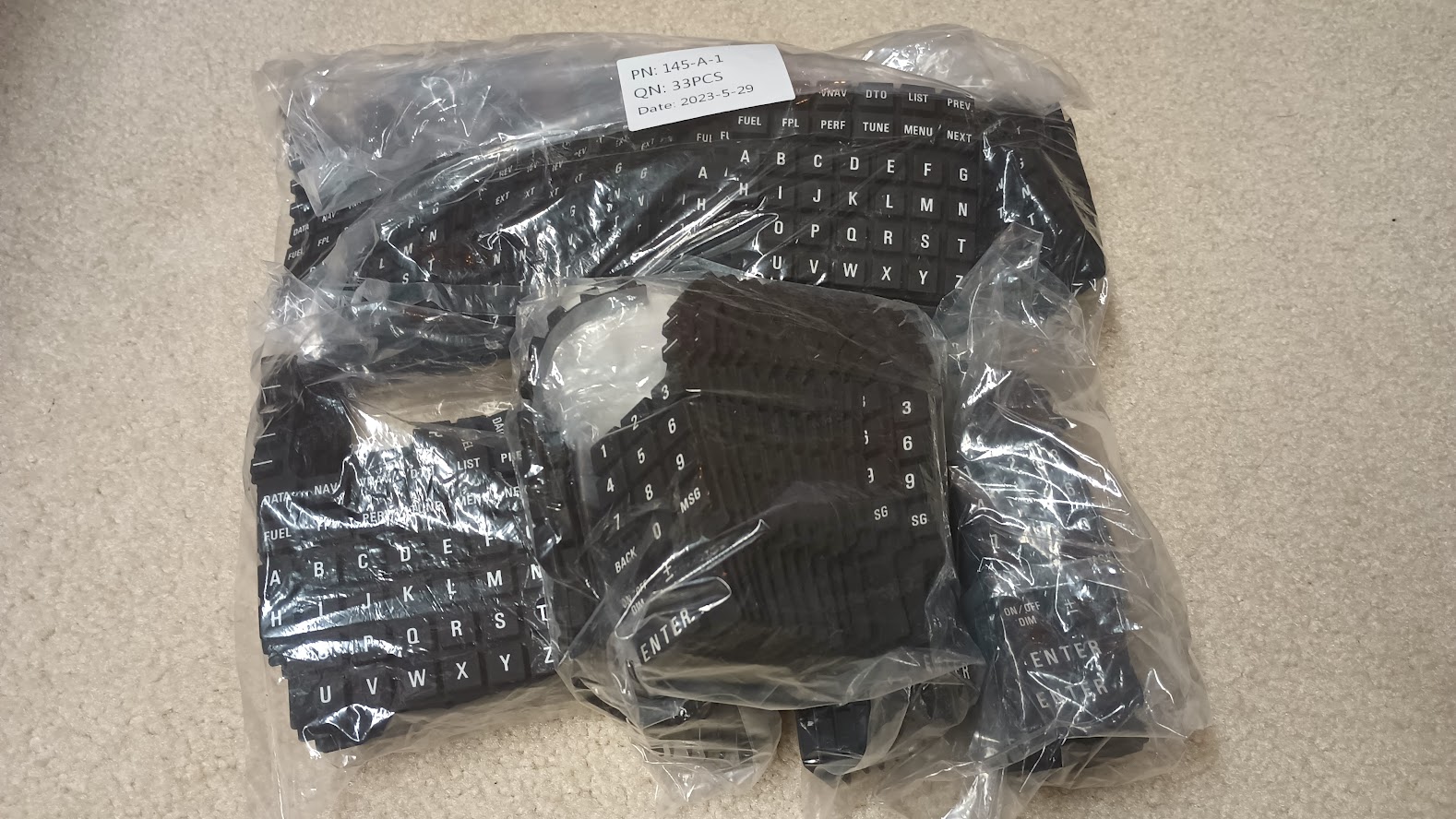
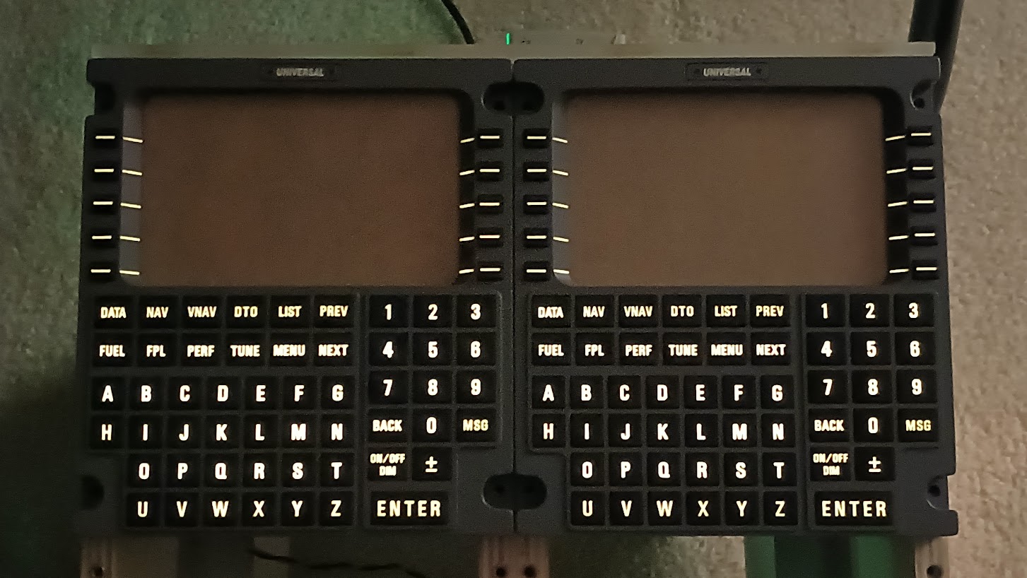
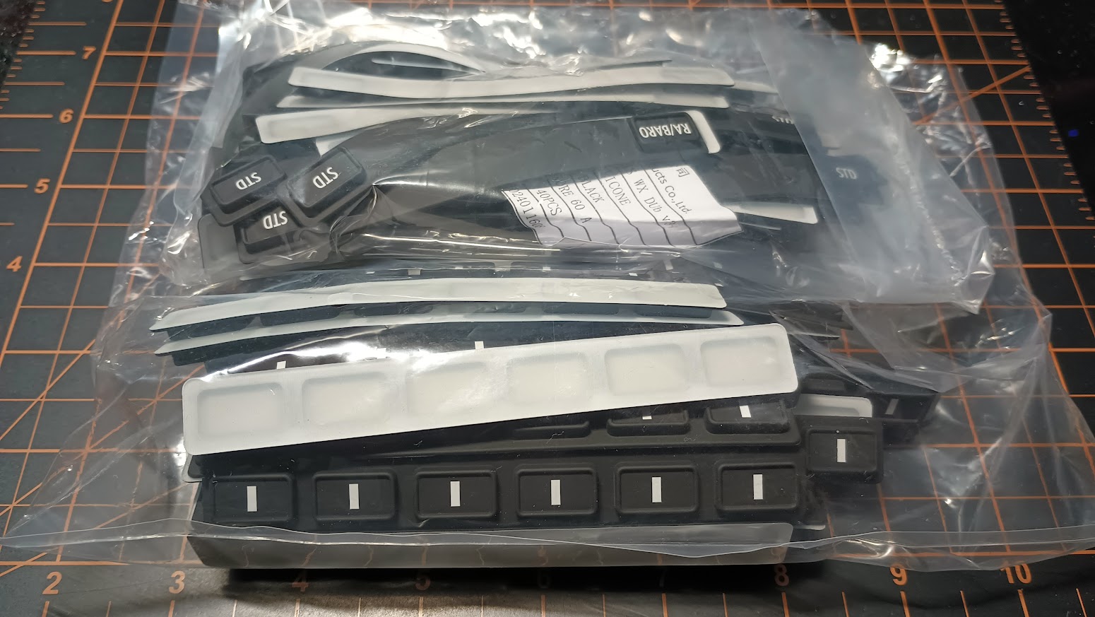
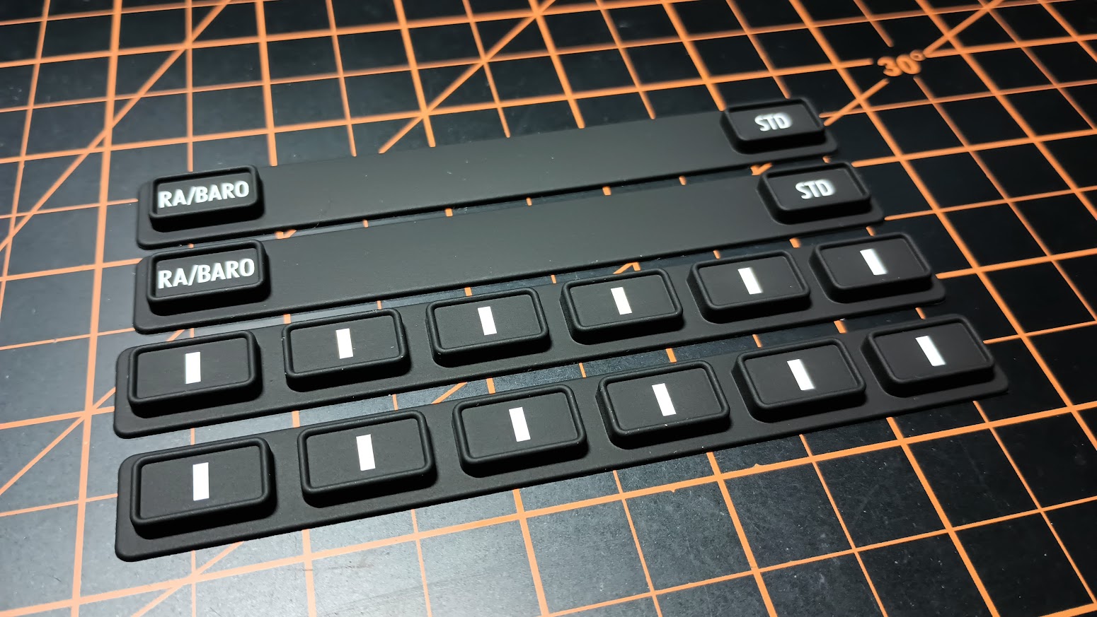
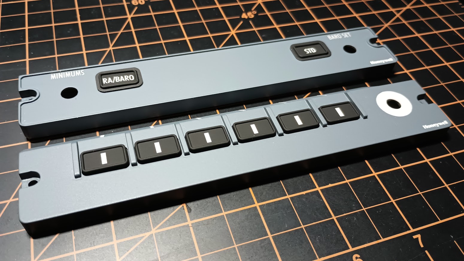
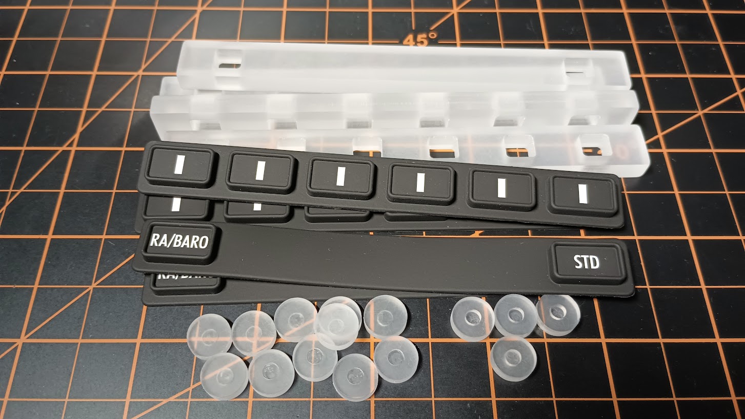
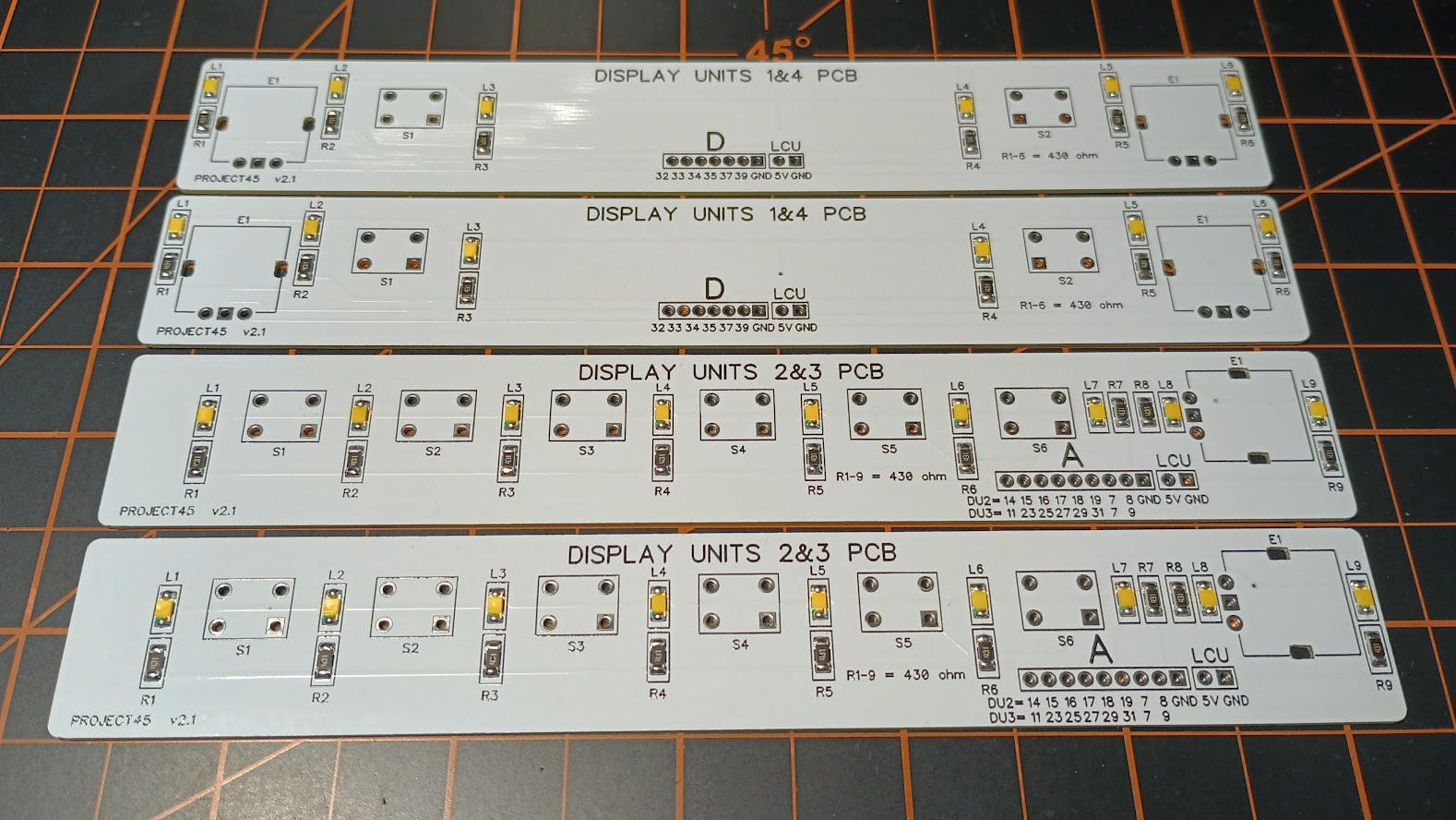
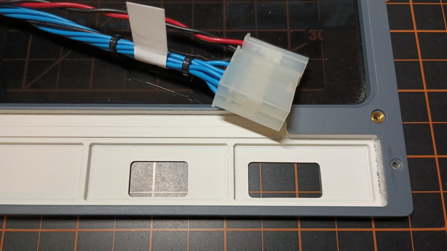
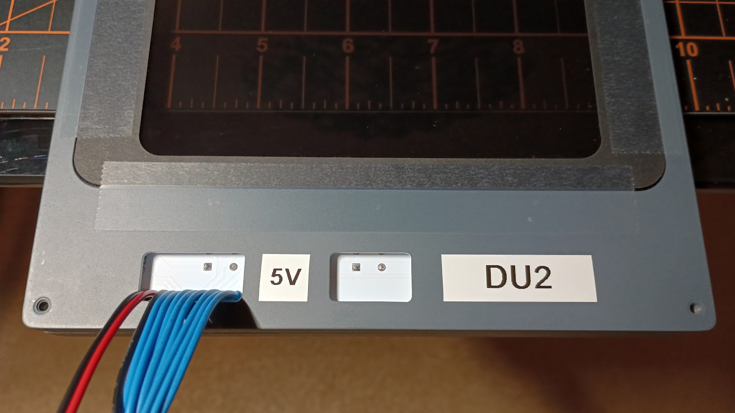
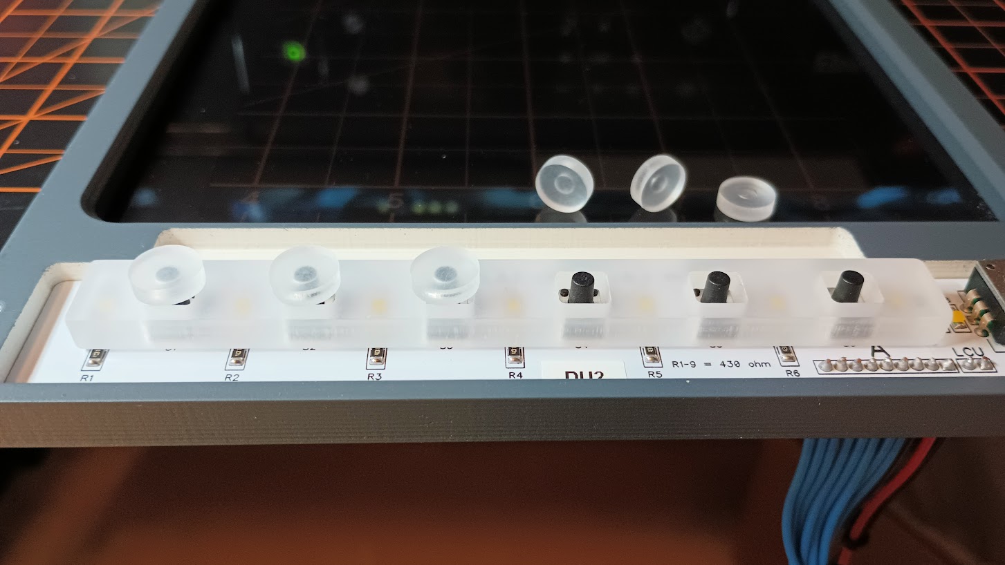
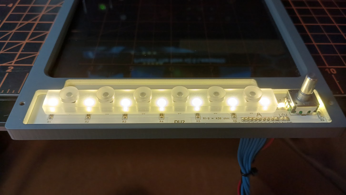
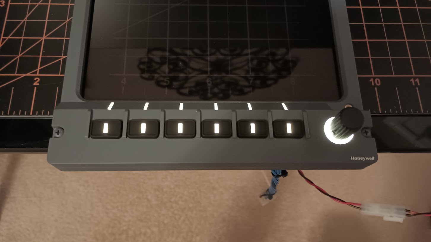
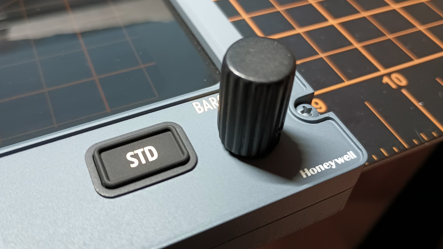
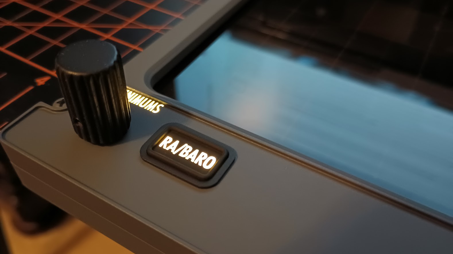
........ and for those who are too nervous for this close soldering turning into a disaster. There is also this option. Wire glue. Just put it into google and other sites for purchase will show up. Coop has recently used it with success so living proof. https://www.ebay.com.au/p/1625012914?iid=143743296536&chn=ps&norover=1&mkevt=1&mkrid=705-139619-5960-0&mkcid=2&itemid=143743296536&targetid=921460872473&device=c&mktype=&googleloc=9072108&poi=&campaignid=10892897993&mkgroupid=107582961032&rlsatarget=pla-921460872473&abcId=9300398&merchantid=119337511&gclid=CjwKCAjw5Kv7BRBSEiwAXGDEleK3zwqdqCS24SOjlzrGTjKHQkD0oBylWlc8uaTiD7EfQtn0W3BIBxoCJ3AQAvD_BwE Mark S. ........ and for those who are too nervous for this close soldering turning into a disaster. There is also this option. Wire glue. Just put it into google and other sites for purchase will show up. Coop has recently used it with success so living proof. Mark S. Hey guys, I have been recently working on a set of Display Units for Terry and over the past two years, I have apparently developed some pcb design skills and thought I would apply it to the internal clad parts! Thanks to Jason Hite for pushing me forward on the Arduino Module design and to Will Sasse for making some suggestions with overseas pcb production, I have become fairly proficient in designing and making pcbs. As a matter of fact, I have found it to be way easier than clad and way less expensive. From here forward, I plan to use professional pcb wherever practical and appropriate. As an example, I will be using pcb in the future v2.0 RMUs and the Project45 CDUs when I get to them. I will still use clad on the larger backlit panels because that is how the real panels are made. Unlike all the Arduino Modules that are the color blue, I decided to make these internal pcbs white in color because they are inside a light chamber. We want warm white light and if we need to tint the color of the light for any reason, we can do that with paper filters. The fit of the new pcb that will be taking place of the old clad is perfect! The only catch is that the clad is .031" thick and the new pcb is .039" thick. You might be thinking, "That's less than .01", what's the big deal?" The thing you might find that you have to do is sand the bottom of the buttons for a minute. I found that I had to do this with my set with the buttons on DU1 and DU4. Without the little bit of sanding, the buttons felt like they did not have the full click once they were pressed. A little sanding of the bottom of the buttons fixed that. The other thing worth mentioning is I believe I soldered the encoder tabs to the clad of all the sets I sent out thinking that they would be there forever. That was a mistake. Trying to desolder to save them is not worth the time and aggravation. So to avoid that headache, I have new encoders included in this free update kit! And, just in case you fear the tiny size 1206 SMDs, I have them solder in place too. However, you will have to desolder the push buttons and the wires from the old clad. I found it super easy to remove from the clad and install on the new pcb. Hopefully you will too. But no worries, if you need me to solder up some buttons, I can do that too. Or if you need replacement DU pcb, I have plenty! One last point, there is no need to feel like you have to immediately pull your sim apart and make this update. The original clad and this new pcb works exactly the same, there is no difference in functionality. I would recommend getting the free upgrade and putting it on your "To do list" the next time you have to pull your MIP out. This update only applies to the Project45 Display Units. If you have a Project45 DU set and would like the free update, just let me know and I will get one out to you ASAP. Hey guys, I have been recently working on a set of Display Units for Terry and over the past two years, I have apparently developed some pcb design skills and thought I would apply it to the internal clad parts! Thanks to Jason Hite for pushing me forward on the Arduino Module design and to Will Sasse for making some suggestions with overseas pcb production, I have become fairly proficient in designing and making pcbs. As a matter of fact, I have found it to be way easier than clad and way less expensive. From here forward, I plan to use professional pcb wherever practical and appropriate. As an example, I will be using pcb in the future v2.0 RMUs and the Project45 CDUs when I get to them. I will still use clad on the larger backlit panels because that is how the real panels are made. Unlike all the Arduino Modules that are the color blue, I decided to make these internal pcbs white in color because they are inside a light chamber. We want warm white light and if we need to tint the color of the light for any reason, we can do that with paper filters. The fit of the new pcb that will be taking place of the old clad is perfect! The only catch is that the clad is .031" thick and the new pcb is .039" thick. You might be thinking, "That's less than .01", what's the big deal?" The thing you might find that you have to do is sand the bottom of the buttons for a minute. I found that I had to do this with my set with the buttons on DU1 and DU4. Without the little bit of sanding, the buttons felt like they did not have the full click once they were pressed. A little sanding of the bottom of the buttons fixed that. The other thing worth mentioning is I believe I soldered the encoder tabs to the clad of all the sets I sent out thinking that they would be there forever. That was a mistake. Trying to desolder to save them is not worth the time and aggravation. So to avoid that headache, I have new encoders included in this free update kit! And, just in case you fear the tiny size 1206 SMDs, I have them solder in place too. However, you will have to desolder the push buttons and the wires from the old clad. I found it super easy to remove from the clad and install on the new pcb. Hopefully you will too. But no worries, if you need me to solder up some buttons, I can do that too. Or if you need replacement DU pcb, I have plenty! One last point, there is no need to feel like you have to immediately pull your sim apart and make this update. The original clad and this new pcb works exactly the same, there is no difference in functionality. I would recommend getting the free upgrade and putting it on your "To do list" the next time you have to pull your MIP out. This update only applies to the Project45 Display Units. If you have a Project45 DU set and would like the free update, just let me know and I will get one out to you ASAP. Hey guys, Another Display Unit Update! Recently we turned to Silicone Keypad production to solve the CDU/FMS button issues. Those issues were there are 63 buttons and it would take forever to manufacture them individually! The positive side effects are superior quality, mass production, lower unit cost, time saved, easy to install, superior light spread and zero light bleed. The process of designing and manufacturing the CDU/FMS Keypads was easy enough that we went ahead and applied this same solution to the RMUs and CDRs! Now the plan forward to to apply Silicone Keypads in every panel that makes sense. We are currently working on the EFIS panels and the WX Radar panels. And that brings us back to the Display Units. We went ahead and designed Silicone Keypads for the Display Units for all the same reasons mentioned above! This way future orders will be delivered much faster and quality will be second to none. I have ordered and received 20 sets of the Display Unit keypads. They fit perfectly in the current Display Units made a couple years back. I am currently working on installing these keypads in the recently made DU sets. It looks like all that is needed is clear button riser. Easy solution. If you have one of my Display Unit sets, you might be interested in a Silicone Keypad update in the near future. More photos and information once I have a set complete with the new Silicone Keypads. Hey guys, Another Display Unit Update! Recently we turned to Silicone Keypad production to solve the CDU/FMS button issues. Those issues were there are 63 buttons and it would take forever to manufacture them individually! The positive side effects are superior quality, mass production, lower unit cost, time saved, easy to install, superior light spread and zero light bleed. The process of designing and manufacturing the CDU/FMS Keypads was easy enough that we went ahead and applied this same solution to the RMUs and CDRs! Now the plan forward to to apply Silicone Keypads in every panel that makes sense. We are currently working on the EFIS panels and the WX Radar panels. And that brings us back to the Display Units. We went ahead and designed Silicone Keypads for the Display Units for all the same reasons mentioned above! This way future orders will be delivered much faster and quality will be second to none. I have ordered and received 20 sets of the Display Unit keypads. They fit perfectly in the current Display Units made a couple years back. I am currently working on installing these keypads in the recently made DU sets. It looks like all that is needed is clear button riser. Easy solution. If you have one of my Display Unit sets, you might be interested in a Silicone Keypad update in the near future. More photos and information once I have a set complete with the new Silicone Keypads. Hey guys, I just completed a set of Display Units with the new Silicone Keypads installed. The update was not as easy as removing the old buttons and replacing them with the new Silicone Keypads. The issue was the thickness of the old buttons compared to the way I had to design the new Silicone keypads. Again, thanks to Will Sasse for helping out with the 3D elements of the drawing! This is not a big deal moving forward making fresh sets of DUs for Hangar45 members, as a matter of fact, it will be easier than ever! But updating an already existing set of DUs require new momentary push buttons that are taller than the previous version. I opted to start with a fresh set of DU pcb because I also wanted to change some wiring colors, but it's possible to remove the short momentary push button switches and replace them with the taller ones. A positive side effect with this change is that the taller momentary switches feel better. They have a stronger tactile feel and at a fraction of the cost. I am providing a free DU update kit to anyone who already has a set of my Display Units, just pay the shipping. Included in the DU update kit will be the Silicone Keypads, replacement pcb with the SMD LEDs and resistors already soldered in place. The momentary buttons will not be soldered on the PCB in case you prefer to remove the momentary switches from the old pcb and install the new switches there. Also included will be a set of internal light plates to help spread the light evenly and individual button lifters. Here is what's included in the DU update kit: While I was updating the Display Units I have here on hand, I went ahead and made a modification to the way the wires come into the bottom of the units. Previously, there was a slot just big enough to slide through the wires with pins attached to them. The better option is to make the opening large enough to pass the plugs through. This way if internal maintenance is required, it's much easier to remove everything. Once the pcb is squared away with the momentary buttons soldered in place, the assembly process is fairly easy. Just lay the pcb in place and lay the internal light plate on top so that the momentary buttons pass through it. Then lay the button lifters on top of the momentary buttons, no glue required. The pressure of the assembly keeps everything were it needs to be. I like to do a light test before we get too much further in case an LED is soldered in backwards. Last but not least, simply lay the Silicone Keypad on top of the button lifters. Then lay the front cover in place and tighten up the two screws! Keep in mind I am using a 9v battery to light this up so it is much brighter than what it really needs to be. And, it's always challenging to take photos of back lighting and show exactly what the naked eye sees. Here are a couple closeup photos of the Silicone in place and why I think you would agree we need to move to Silicone keypads wherever possible. Very clean! And zero light bleed because the Silicone web acts as a rubber gasket. And that it! Two reasons why we opted to move to Silicone for these and so many other panels, higher quality and easier/faster manufacturing. Making the buttons are always the hardest part of panel building, not anymore. If you already have the Project45 Display Units and would like this free update kit, just send me an email! The next update on this thread will include the DUs actually installed on the MIP with Jet45 AAS running! Hey guys, I just completed a set of Display Units with the new Silicone Keypads installed. The update was not as easy as removing the old buttons and replacing them with the new Silicone Keypads. The issue was the thickness of the old buttons compared to the way I had to design the new Silicone keypads. Again, thanks to Will Sasse for helping out with the 3D elements of the drawing! This is not a big deal moving forward making fresh sets of DUs for Hangar45 members, as a matter of fact, it will be easier than ever! But updating an already existing set of DUs require new momentary push buttons that are taller than the previous version. I opted to start with a fresh set of DU pcb because I also wanted to change some wiring colors, but it's possible to remove the short momentary push button switches and replace them with the taller ones. A positive side effect with this change is that the taller momentary switches feel better. They have a stronger tactile feel and at a fraction of the cost. I am providing a free DU update kit to anyone who already has a set of my Display Units, just pay the shipping. Included in the DU update kit will be the Silicone Keypads, replacement pcb with the SMD LEDs and resistors already soldered in place. The momentary buttons will not be soldered on the PCB in case you prefer to remove the momentary switches from the old pcb and install the new switches there. Also included will be a set of internal light plates to help spread the light evenly and individual button lifters. Here is what's included in the DU update kit: While I was updating the Display Units I have here on hand, I went ahead and made a modification to the way the wires come into the bottom of the units. Previously, there was a slot just big enough to slide through the wires with pins attached to them. The better option is to make the opening large enough to pass the plugs through. This way if internal maintenance is required, it's much easier to remove everything. Once the pcb is squared away with the momentary buttons soldered in place, the assembly process is fairly easy. Just lay the pcb in place and lay the internal light plate on top so that the momentary buttons pass through it. Then lay the button lifters on top of the momentary buttons, no glue required. The pressure of the assembly keeps everything were it needs to be. I like to do a light test before we get too much further in case an LED is soldered in backwards. Last but not least, simply lay the Silicone Keypad on top of the button lifters. Then lay the front cover in place and tighten up the two screws! Keep in mind I am using a 9v battery to light this up so it is much brighter than what it really needs to be. And, it's always challenging to take photos of back lighting and show exactly what the naked eye sees. Here are a couple closeup photos of the Silicone in place and why I think you would agree we need to move to Silicone keypads wherever possible. Very clean! And zero light bleed because the Silicone web acts as a rubber gasket. And that it! Two reasons why we opted to move to Silicone for these and so many other panels, higher quality and easier/faster manufacturing. Making the buttons are always the hardest part of panel building, not anymore. If you already have the Project45 Display Units and would like this free update kit, just send me an email! The next update on this thread will include the DUs actually installed on the MIP with Jet45 AAS running!Display Unit Development by Project45
![]()
![]()
![]()
![]()
2017-10-10