


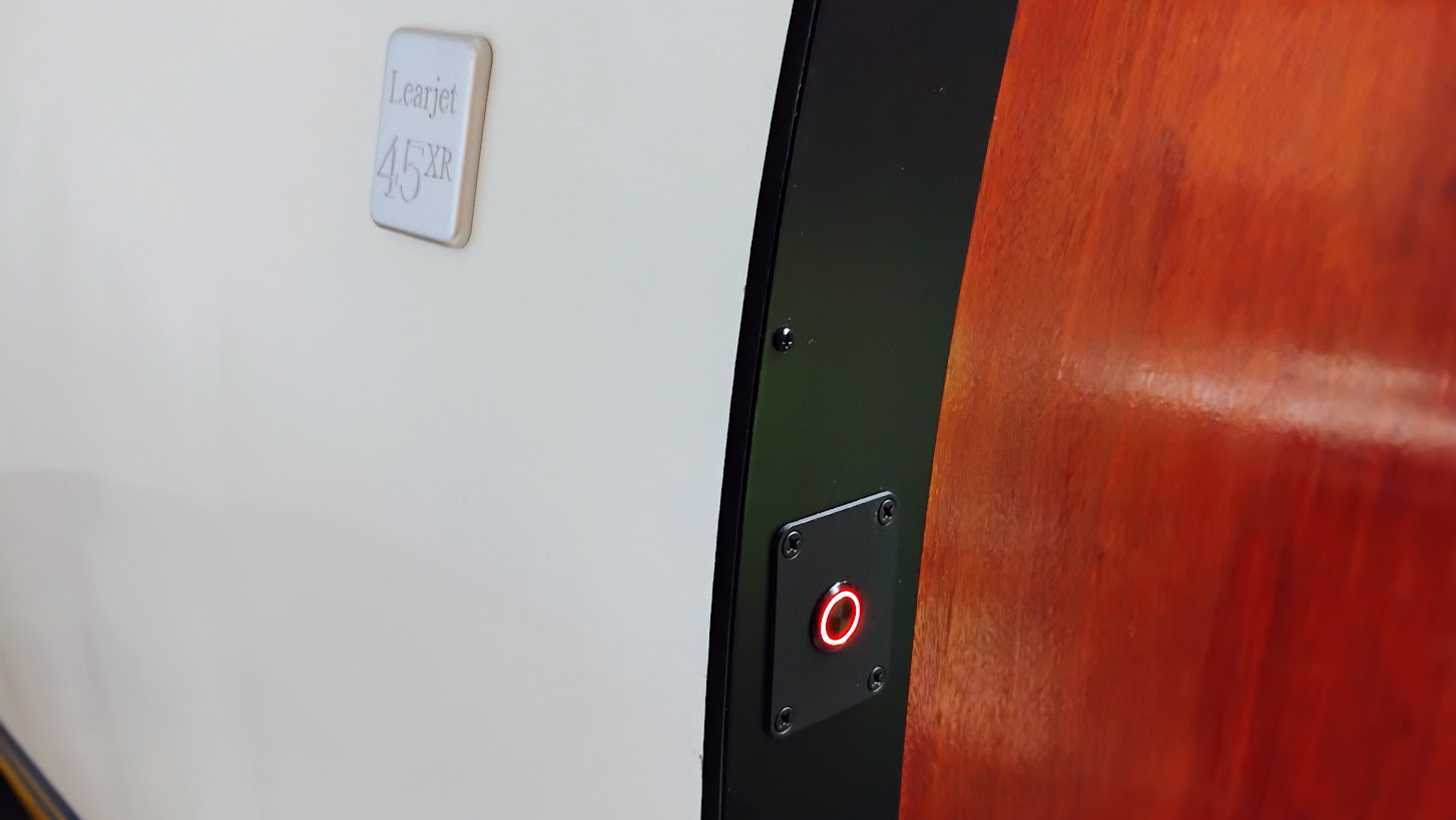
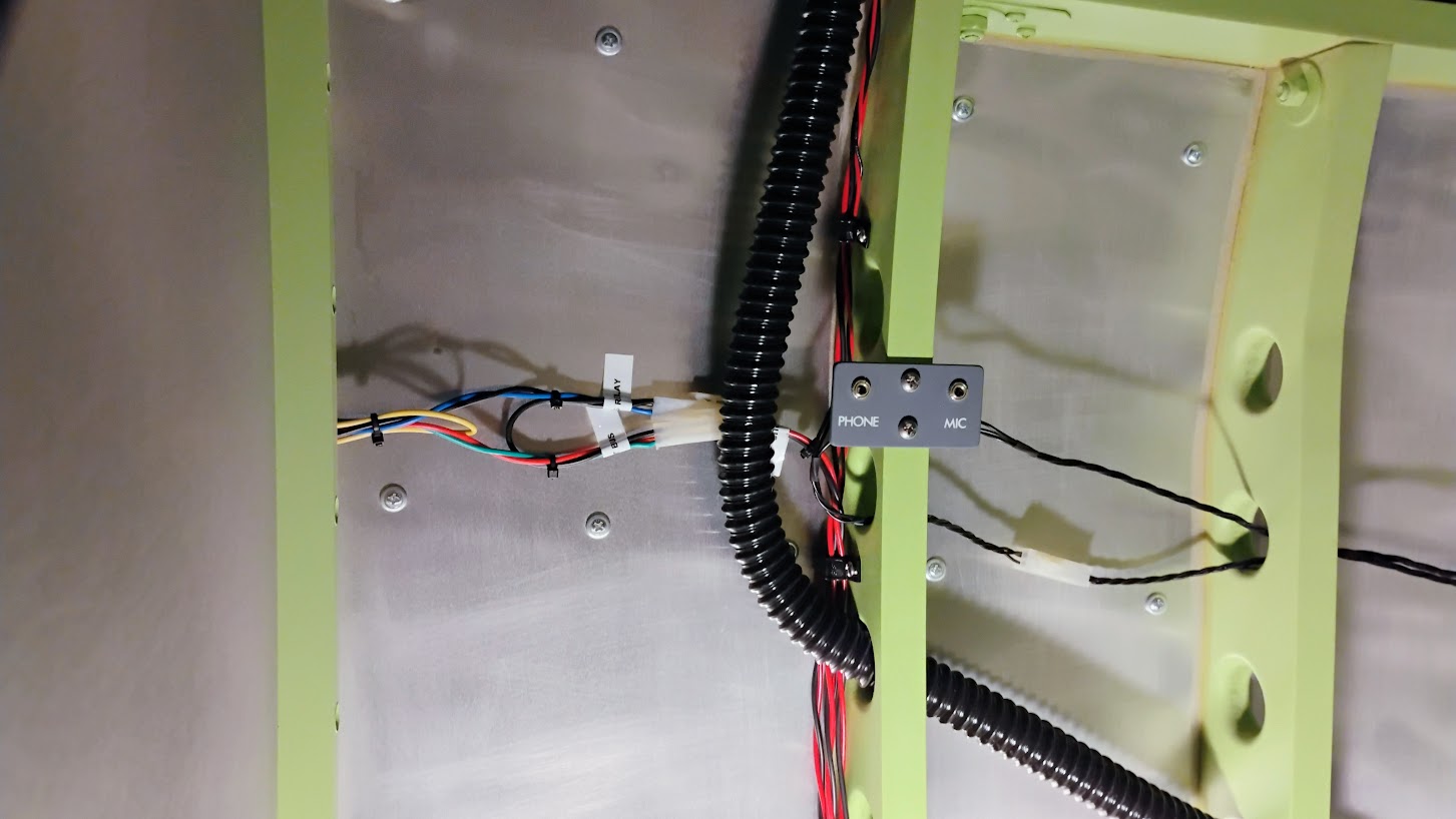
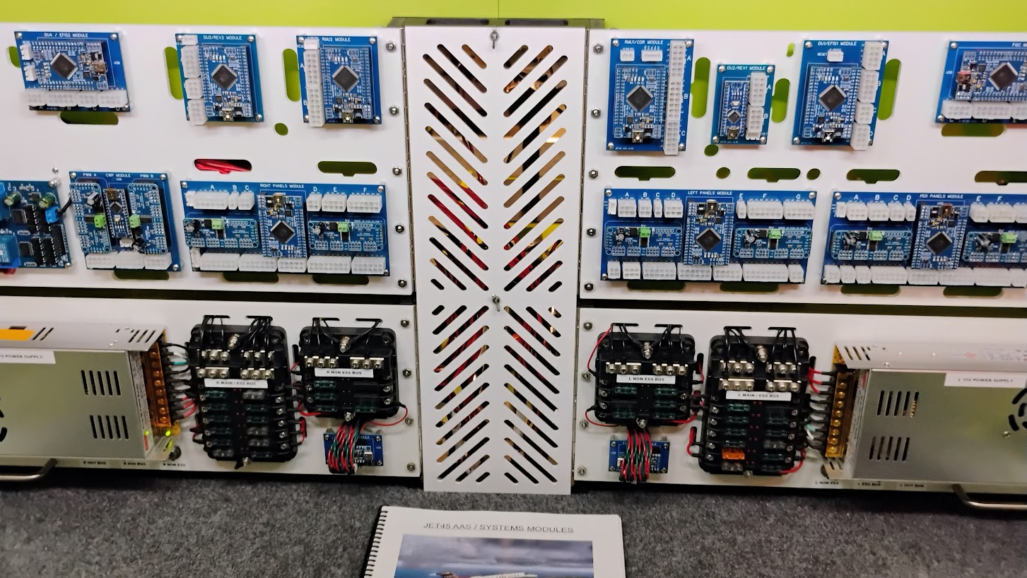
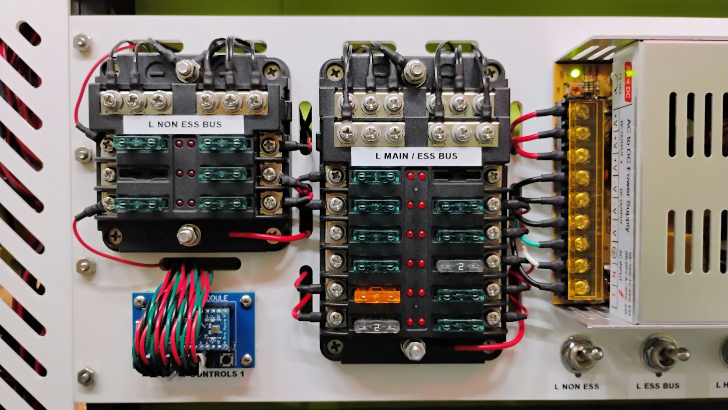
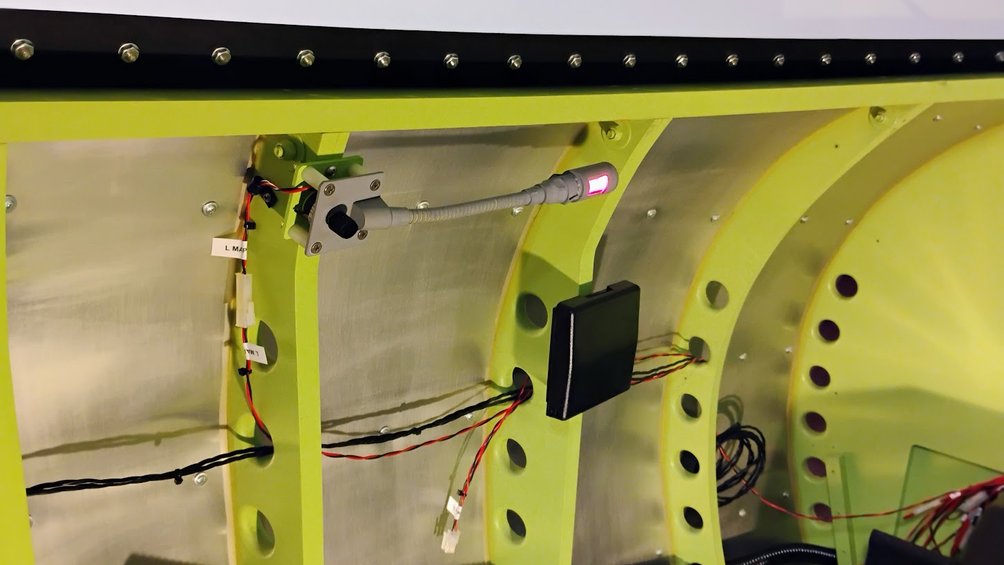
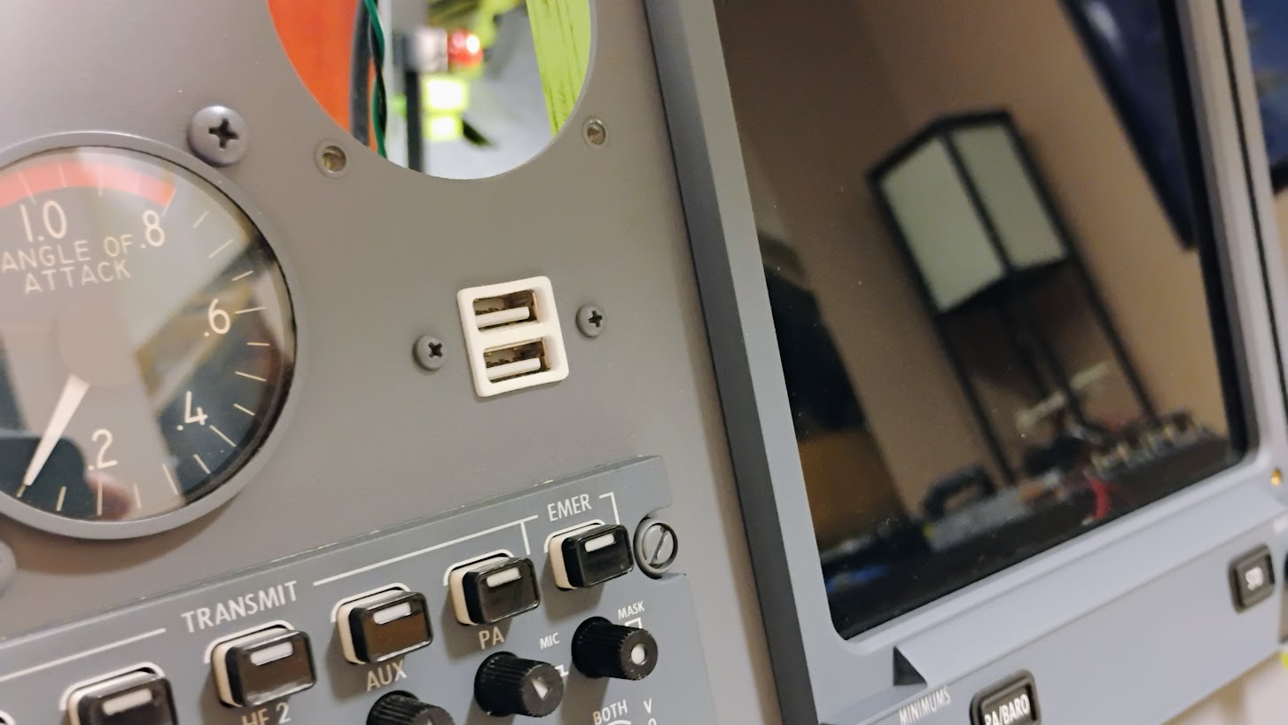
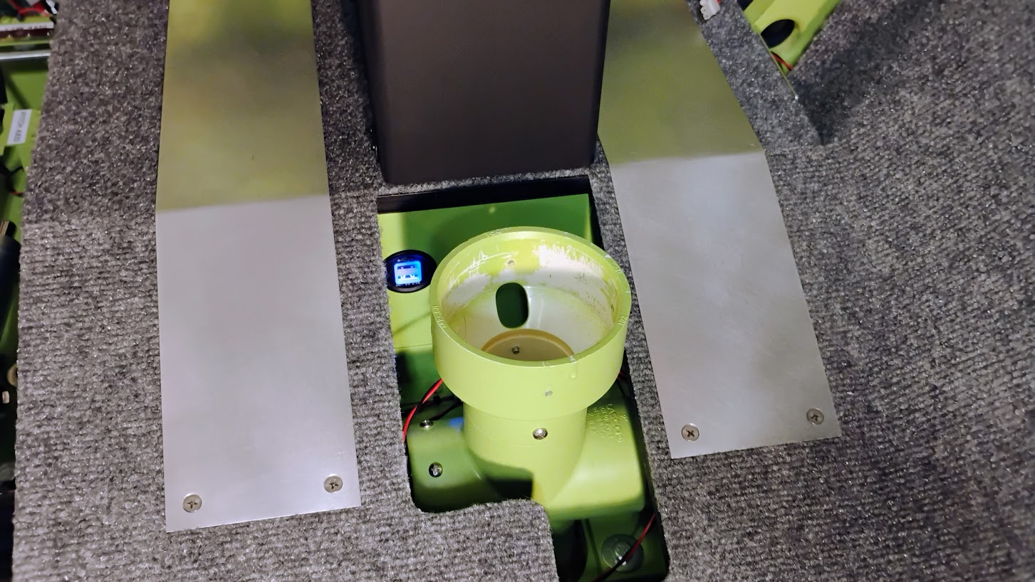
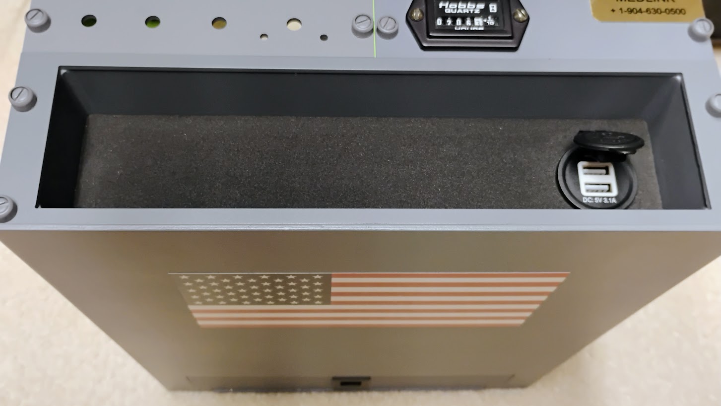
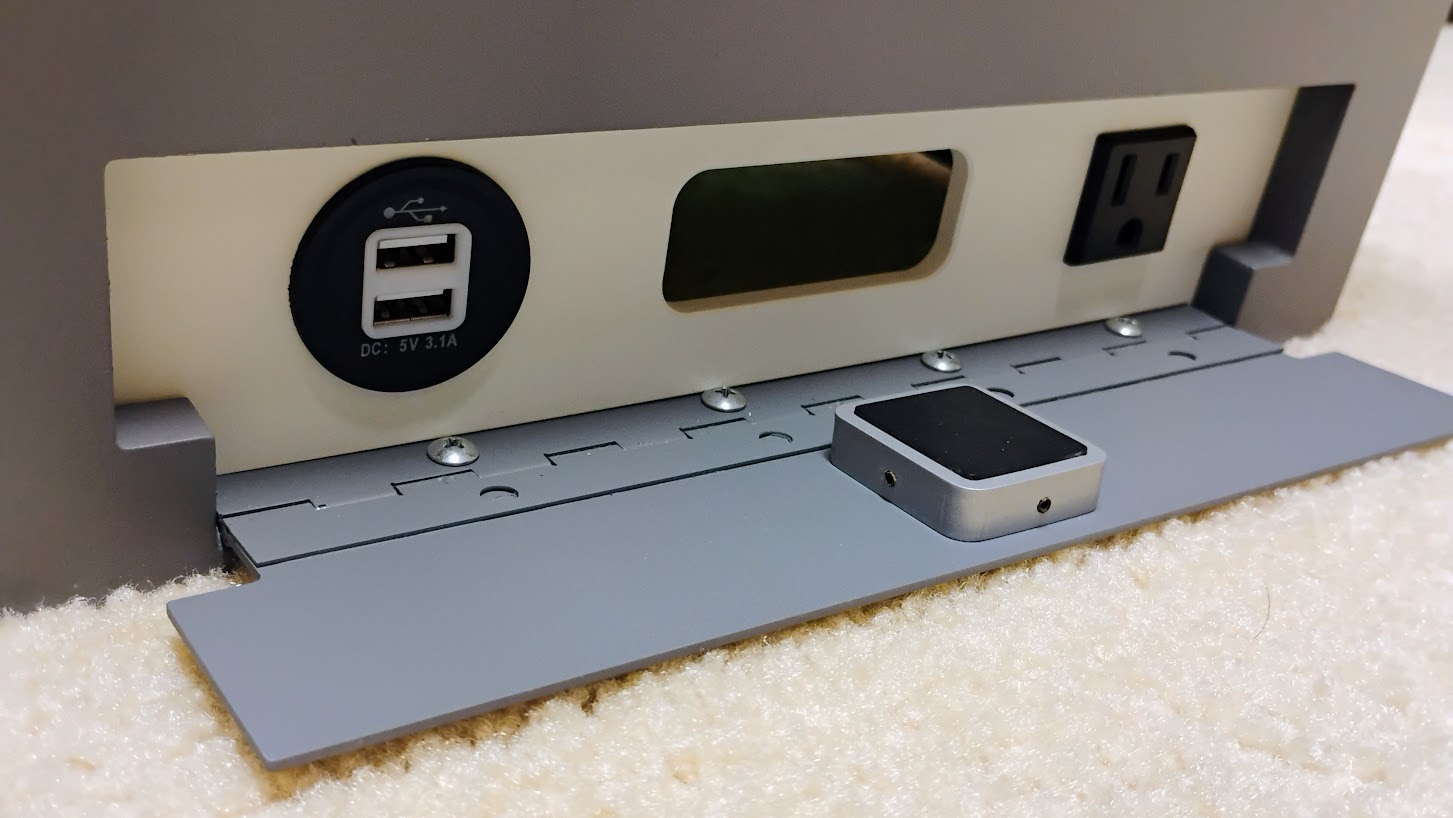
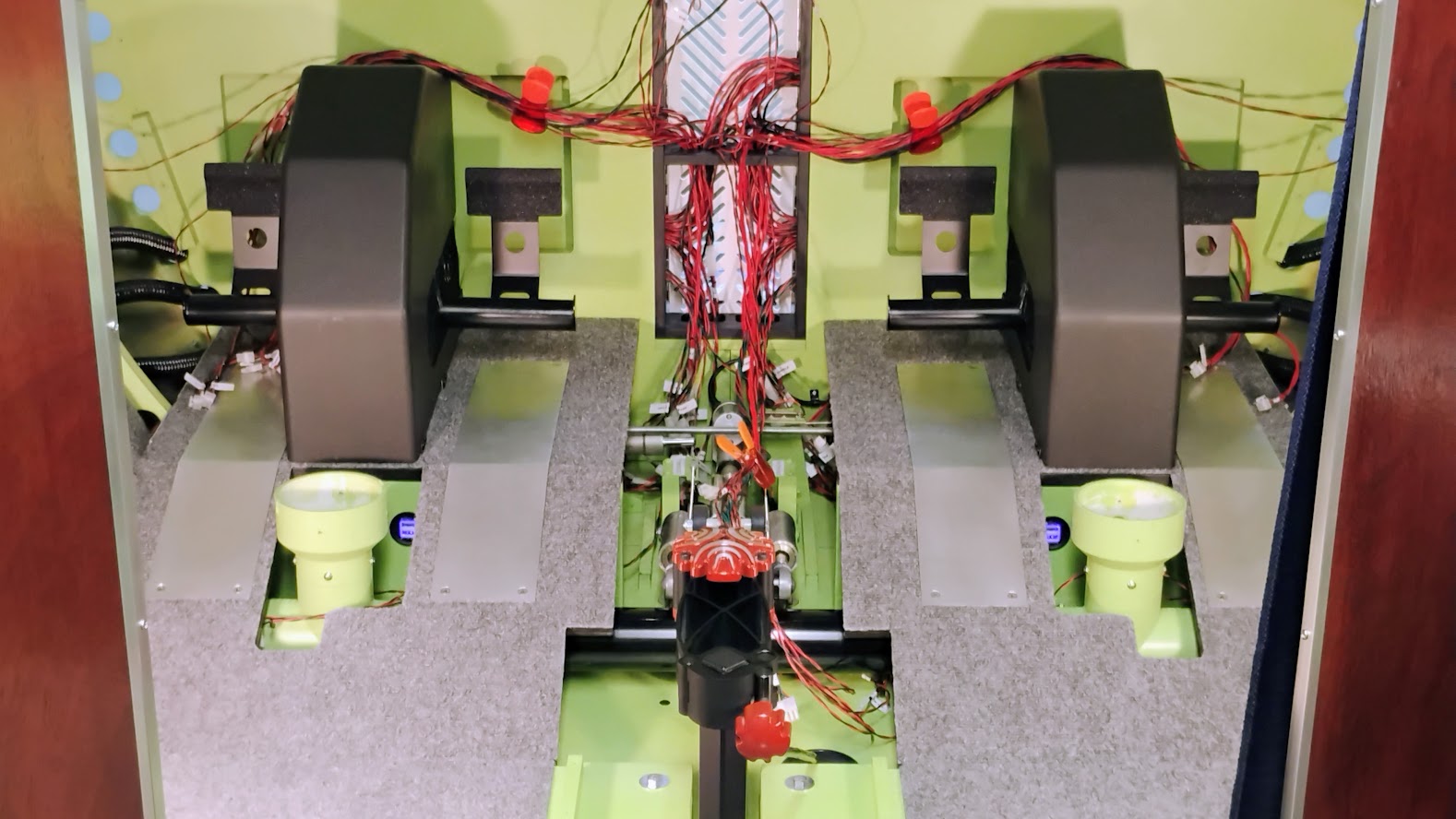
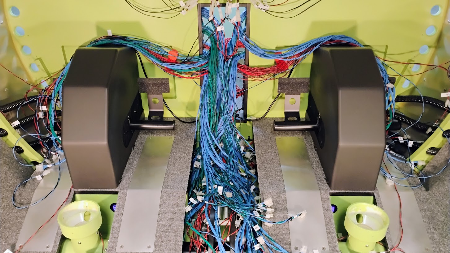
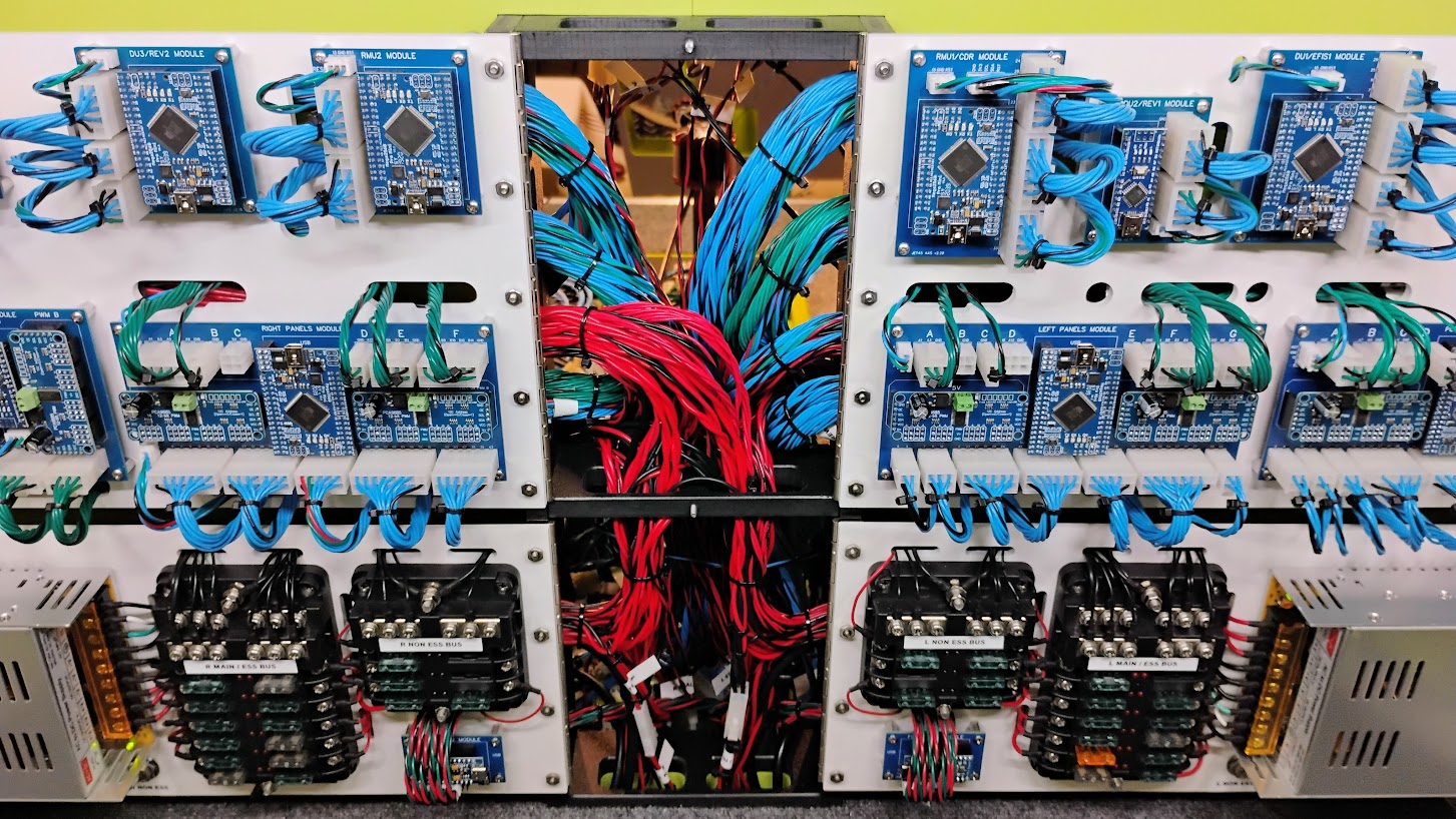
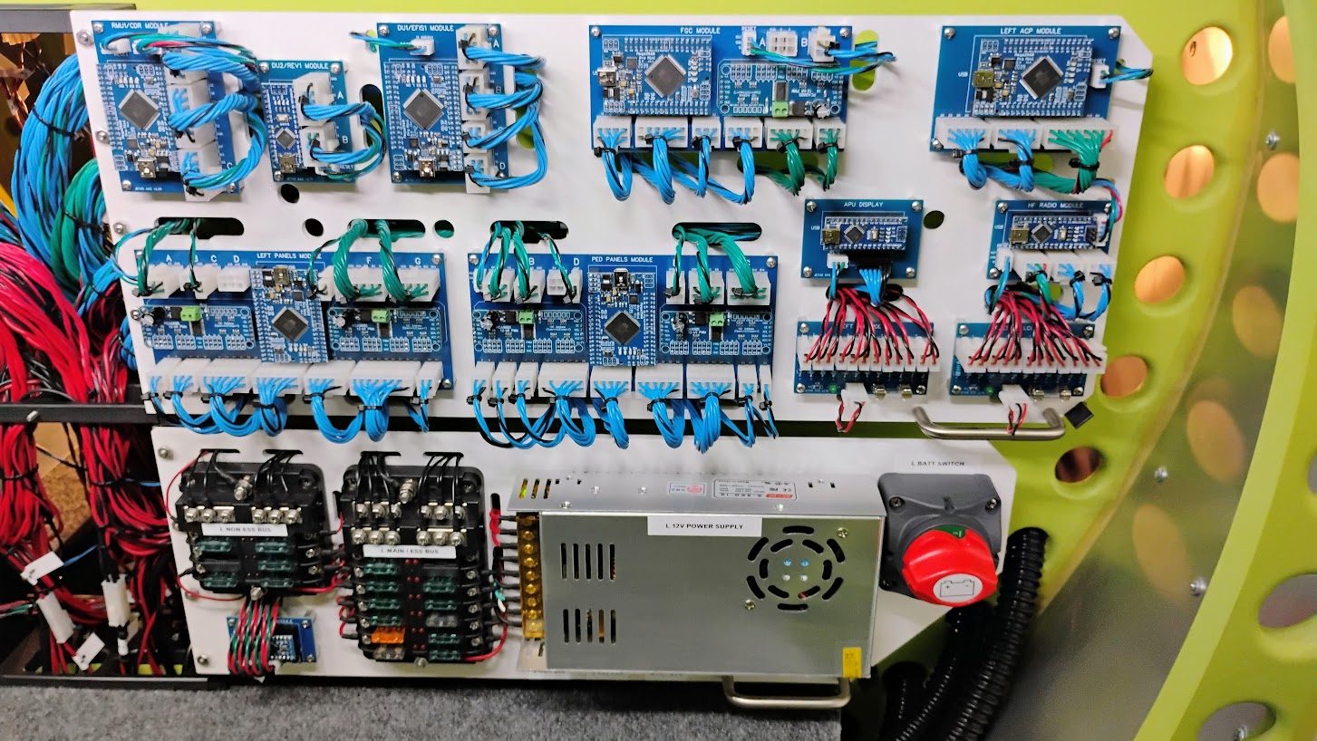
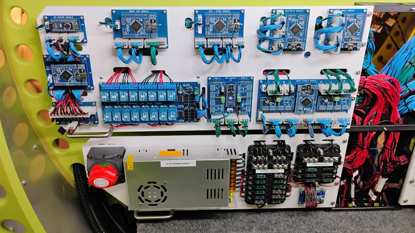
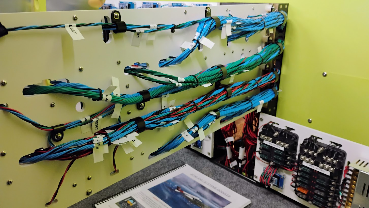
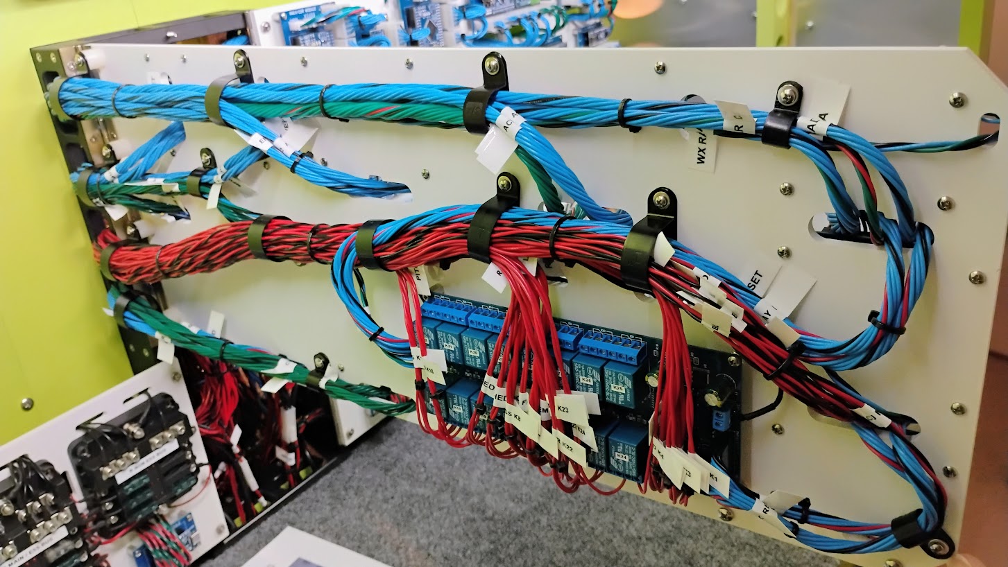
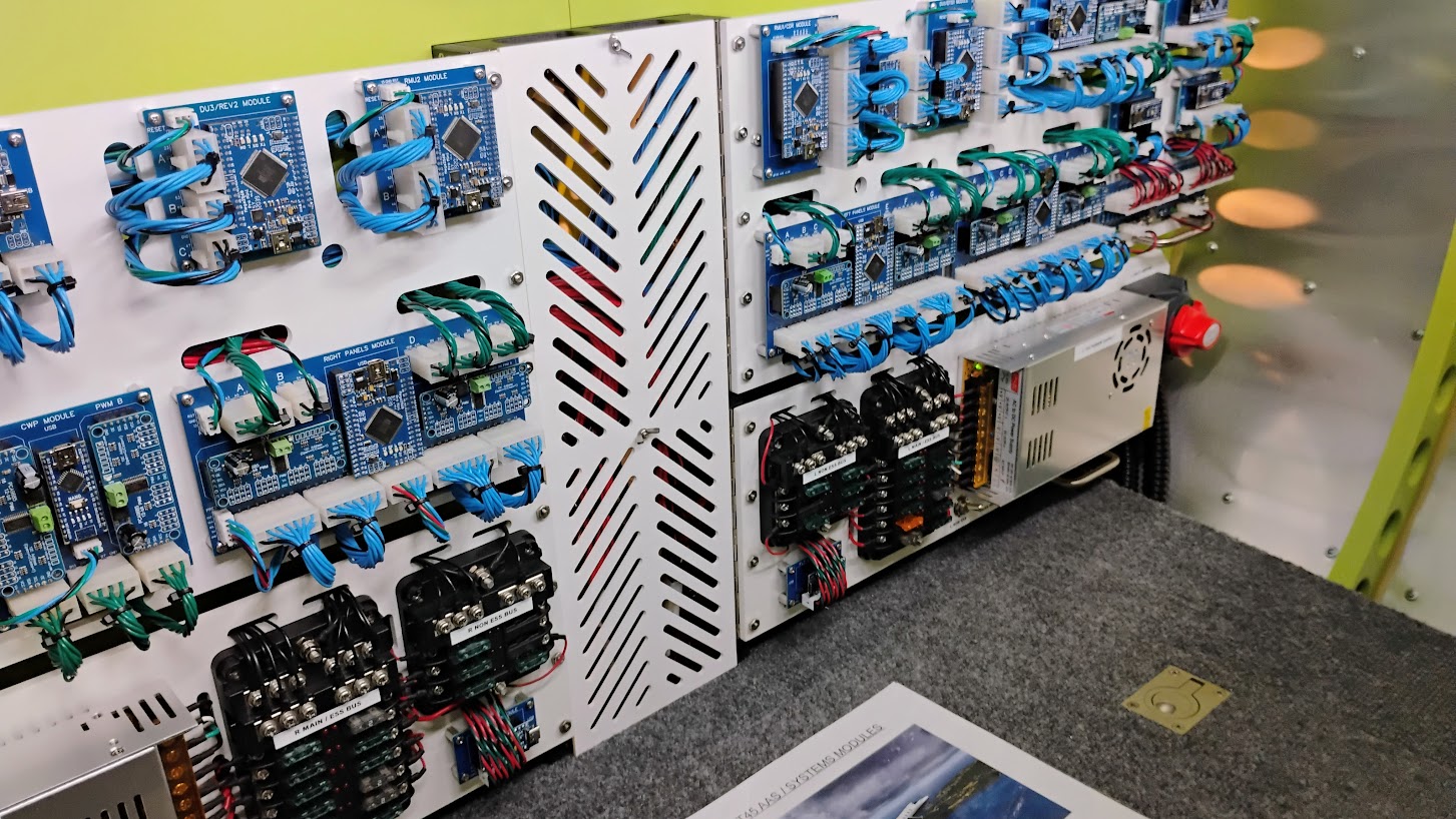
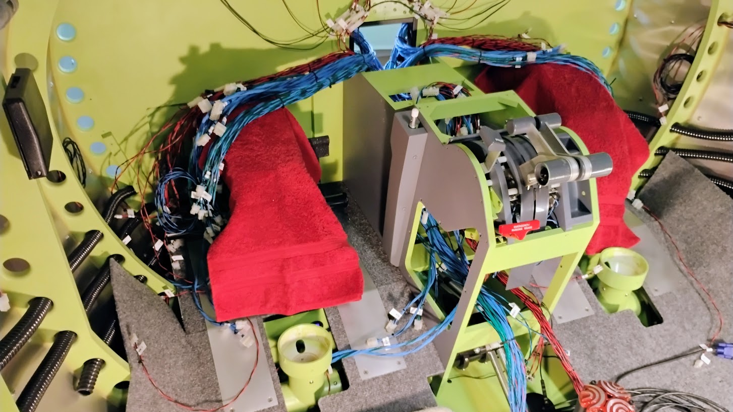
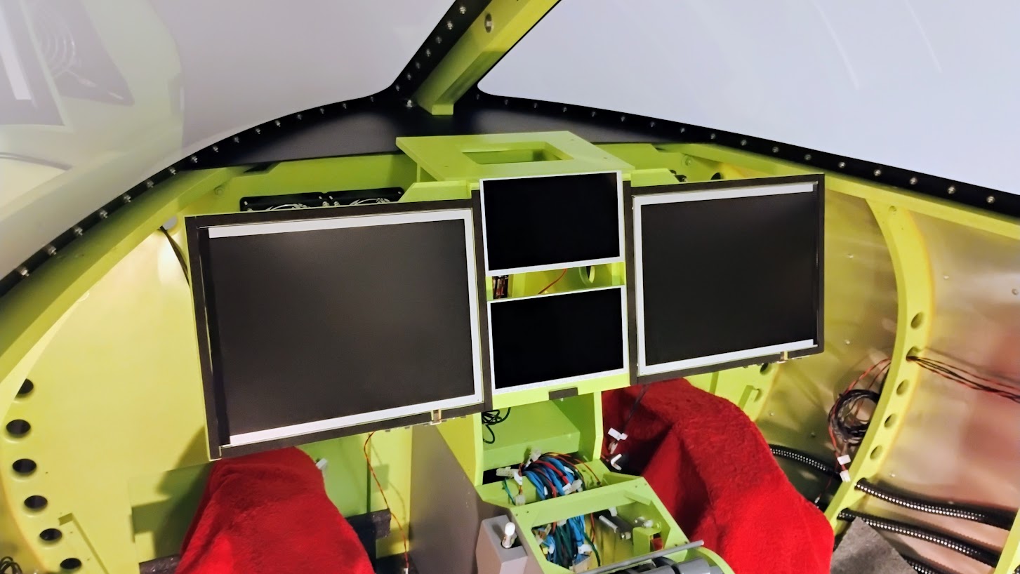
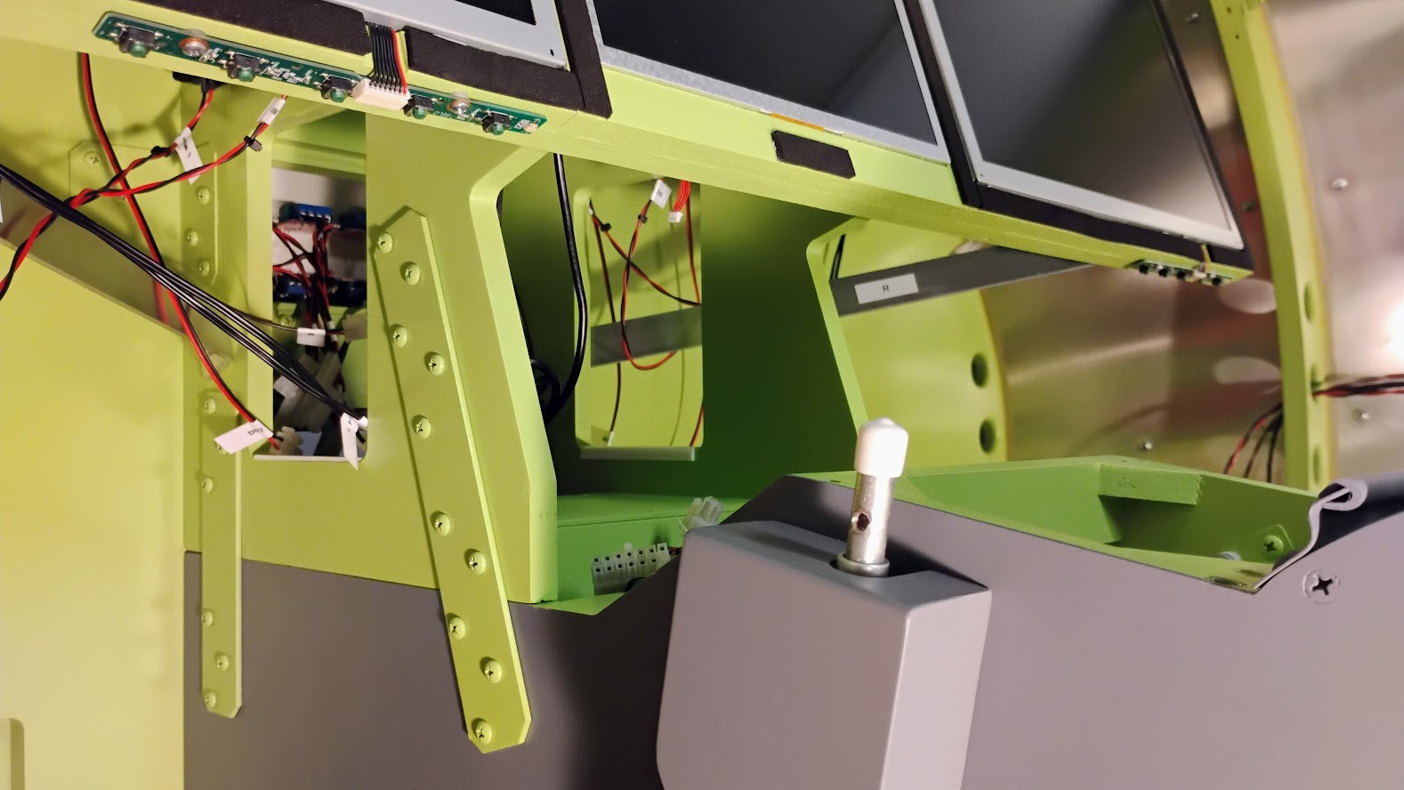
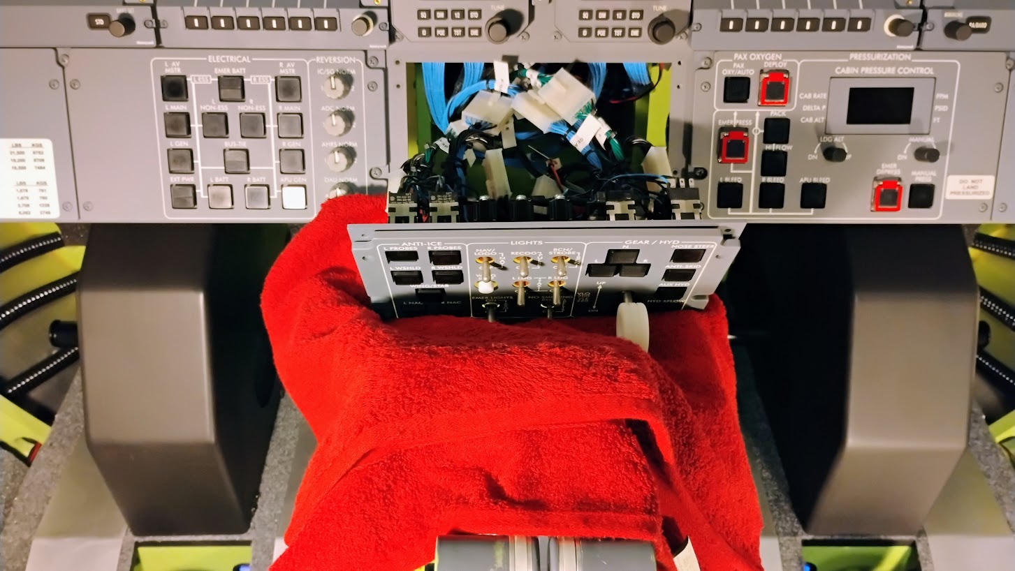
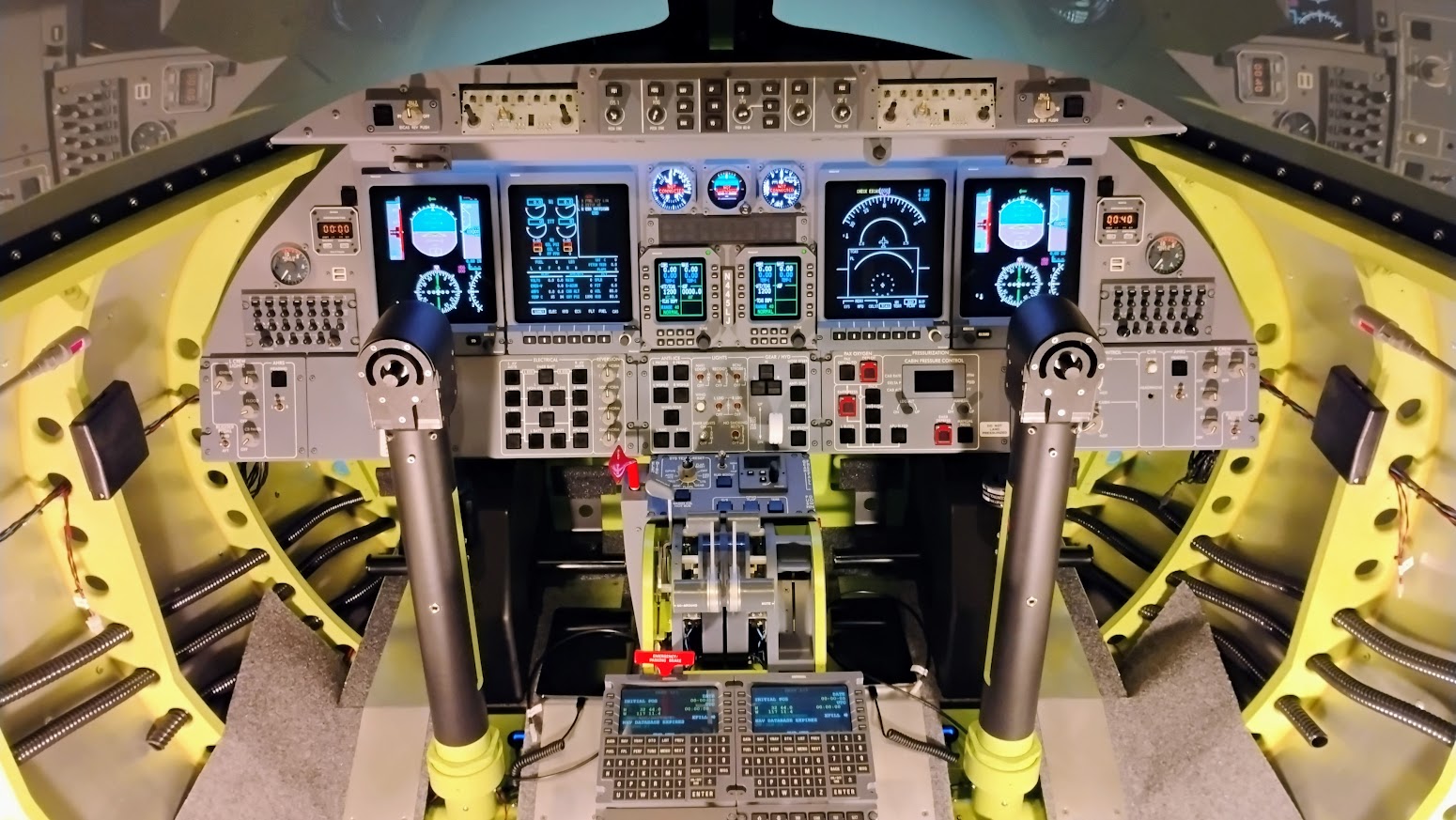
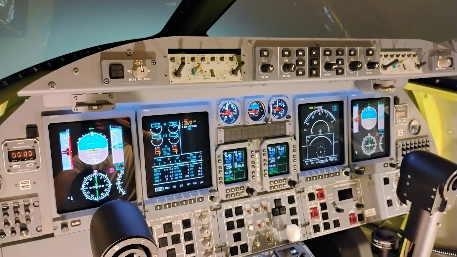
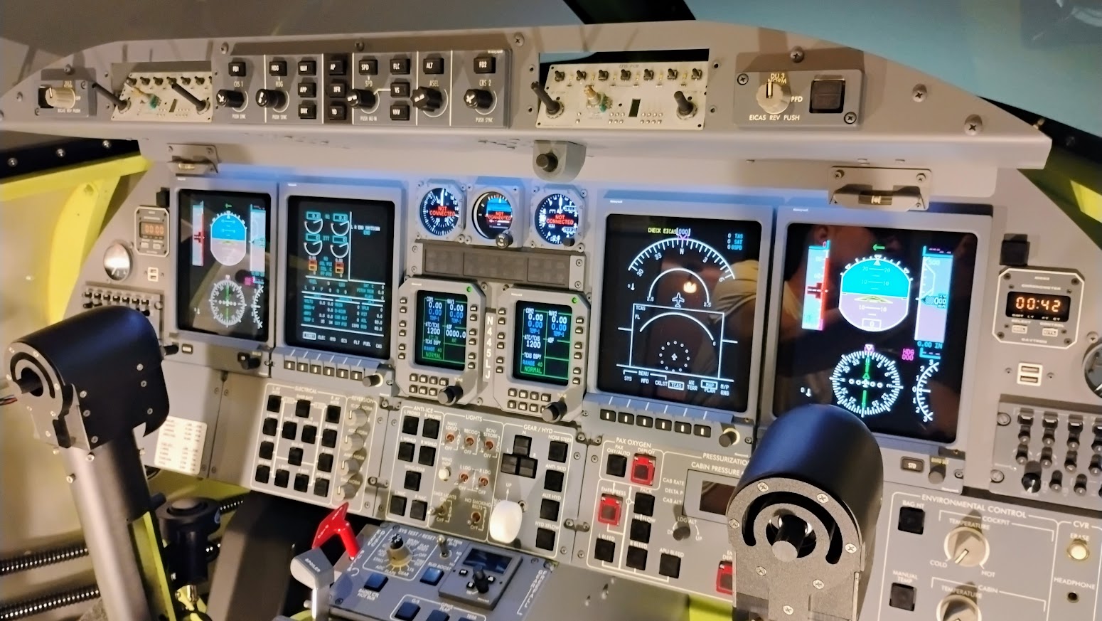
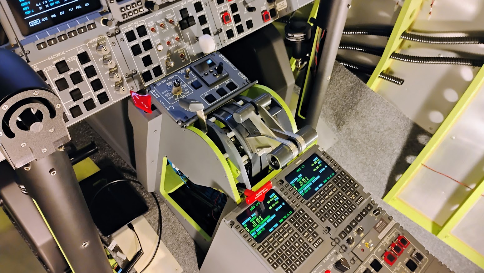
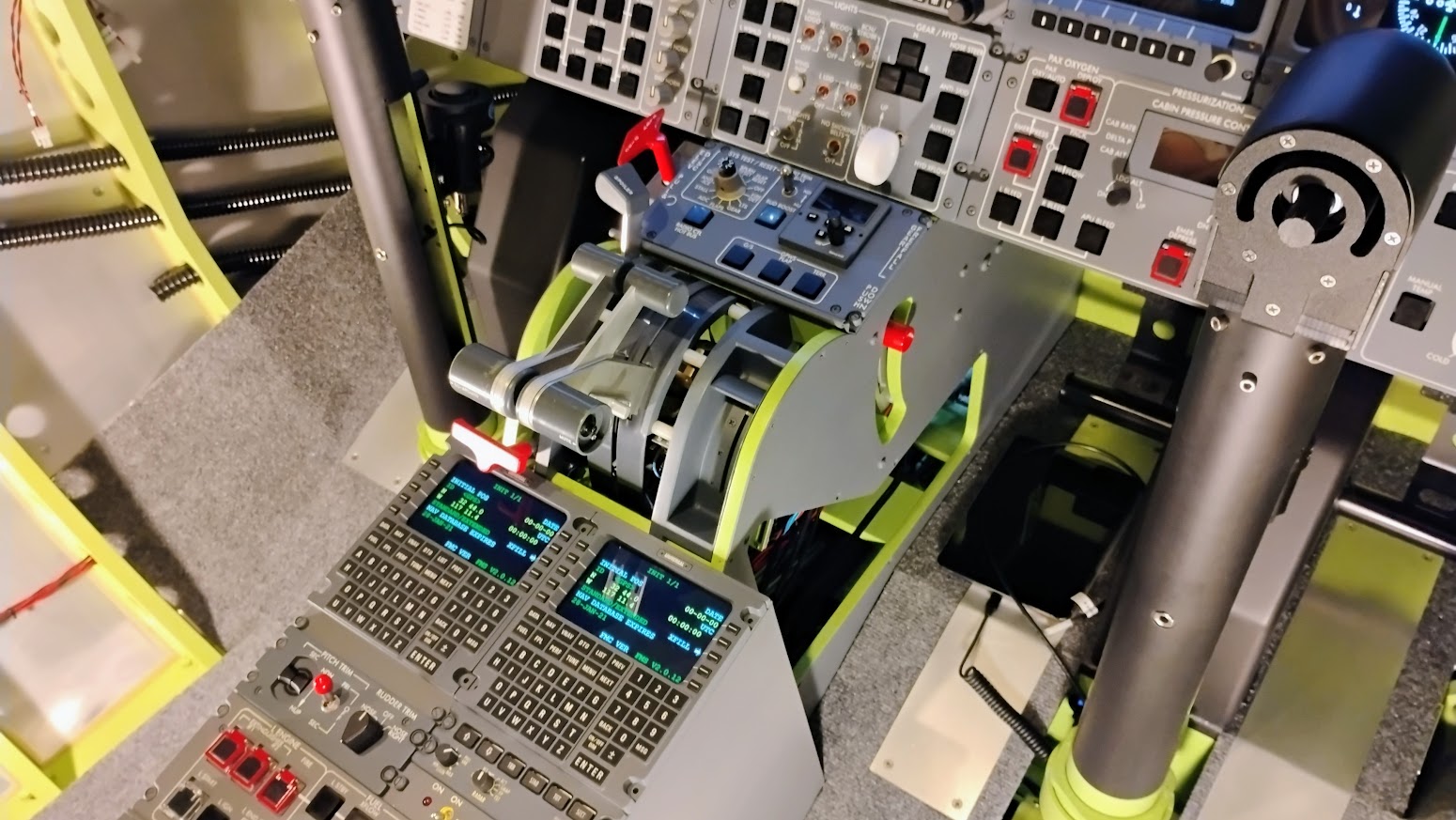
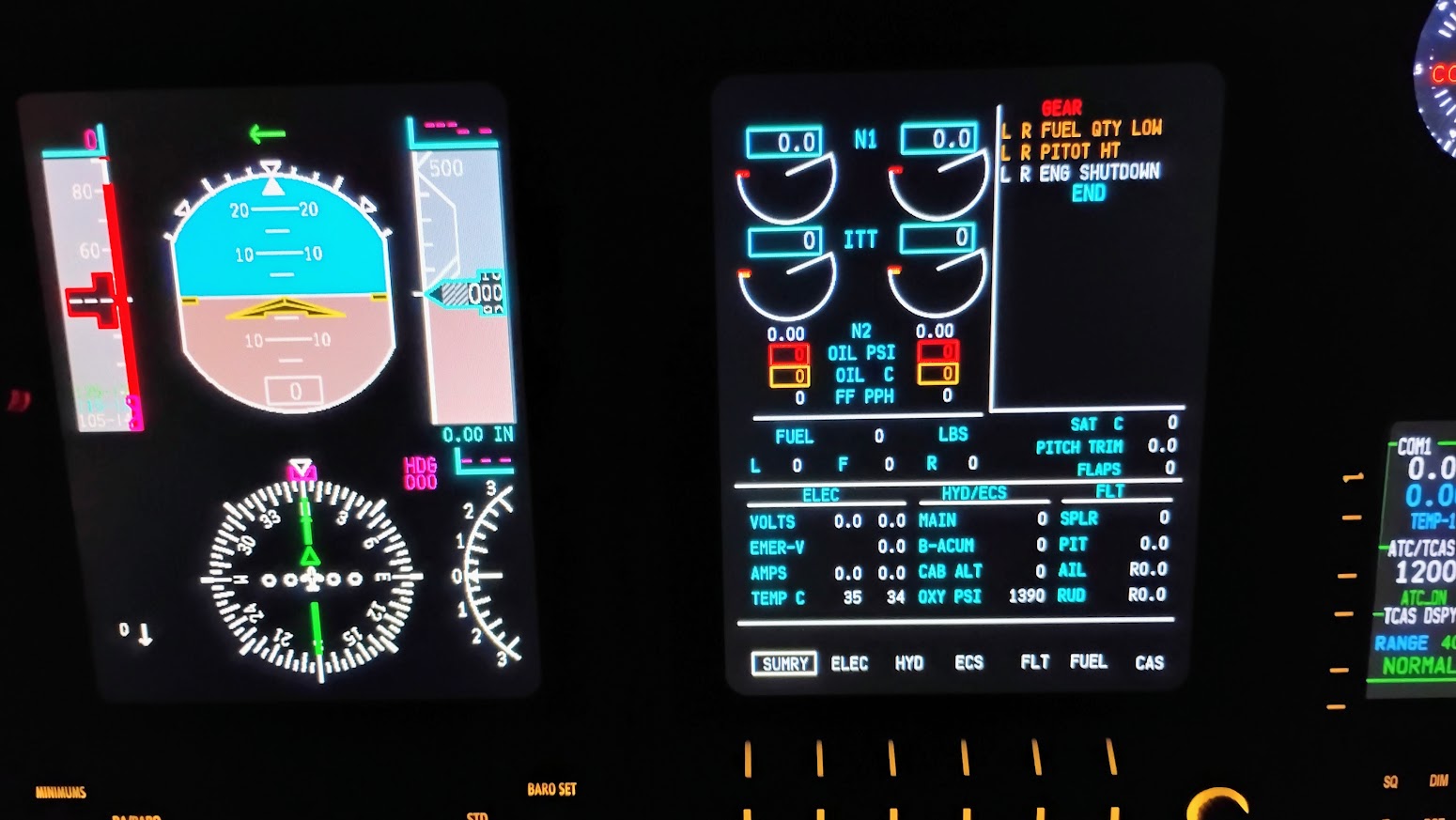
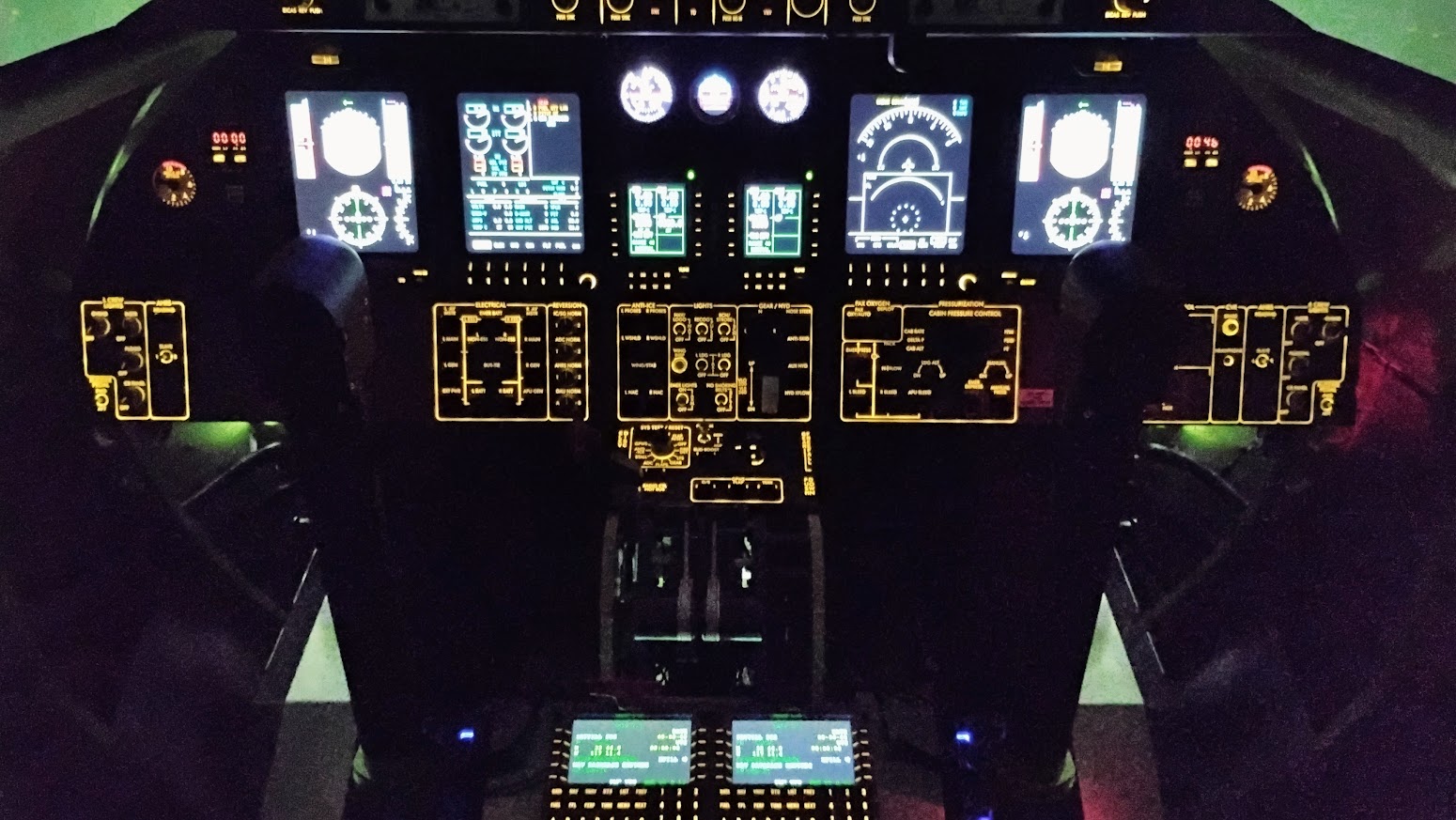
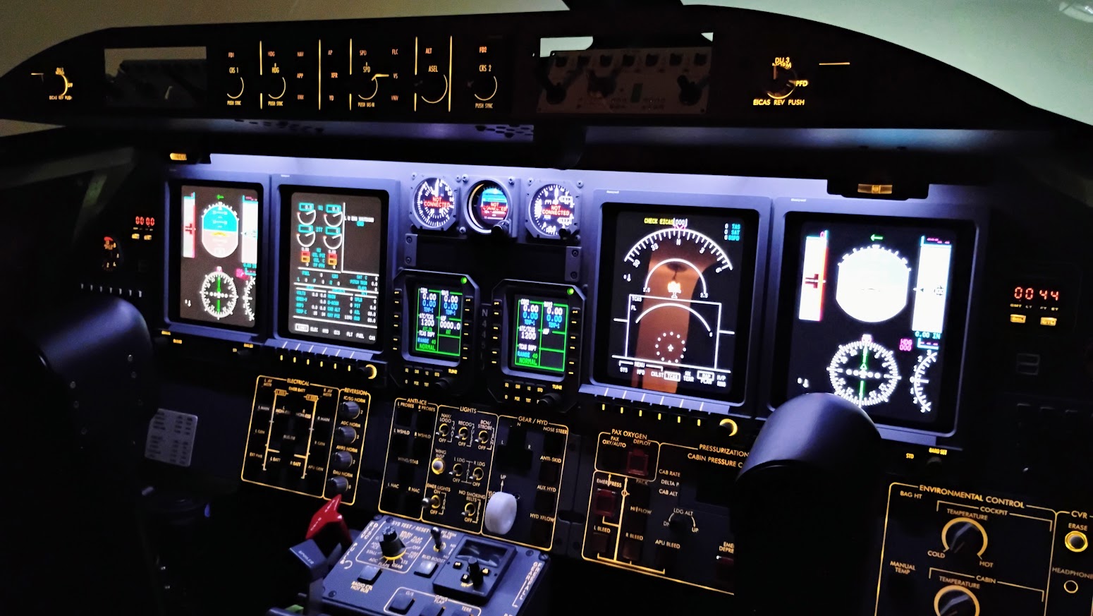
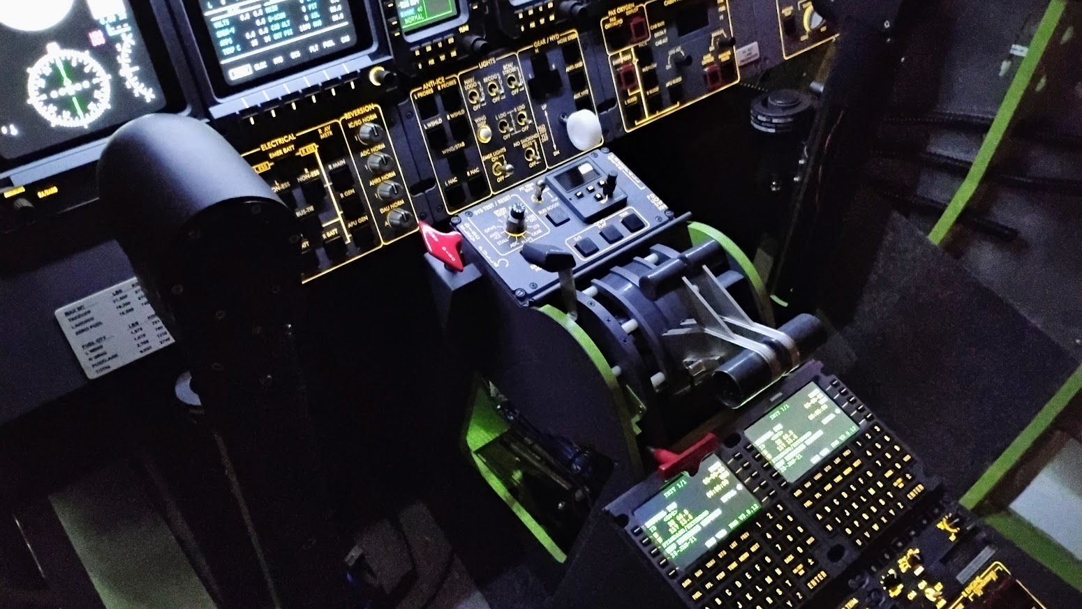
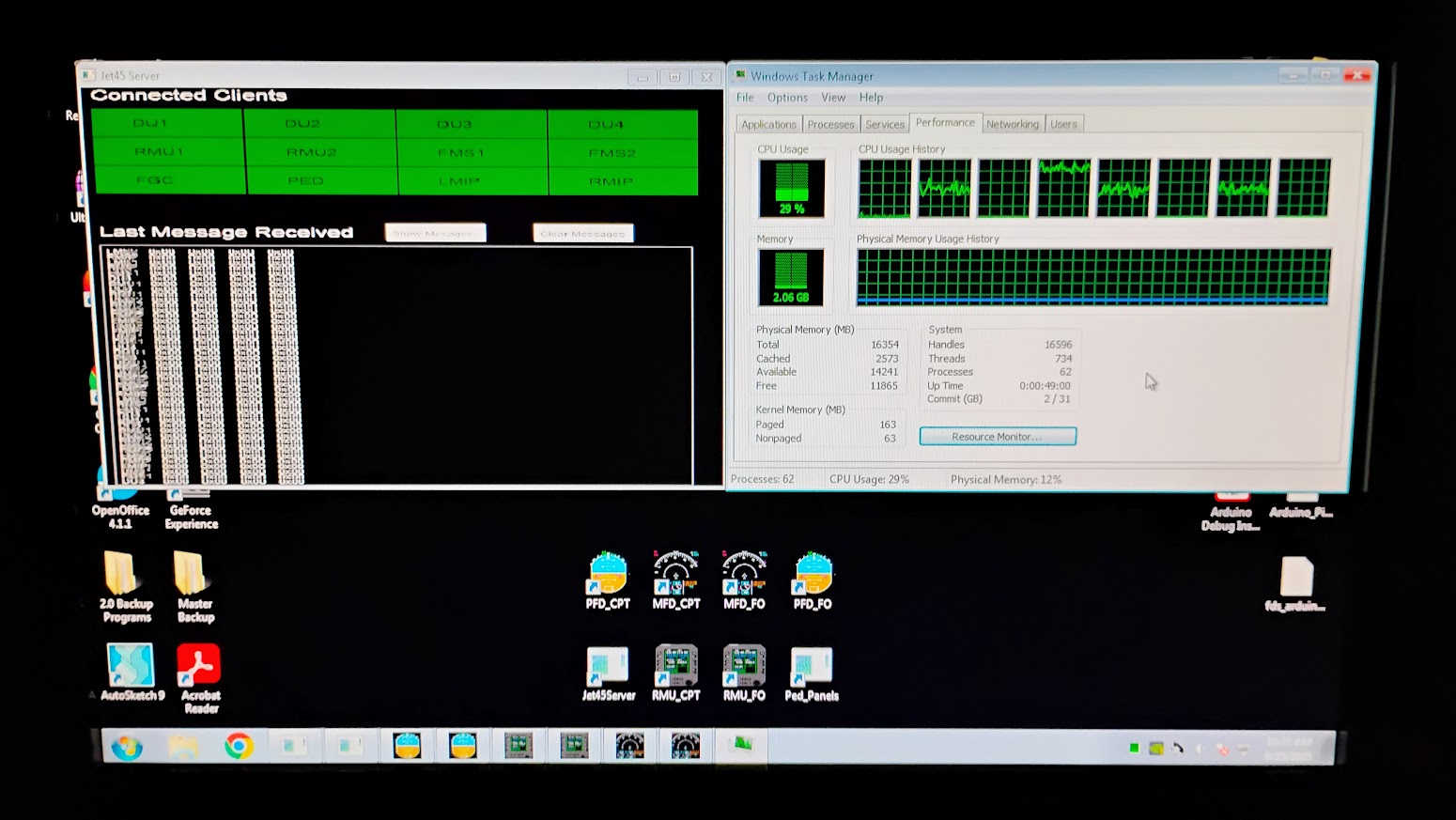
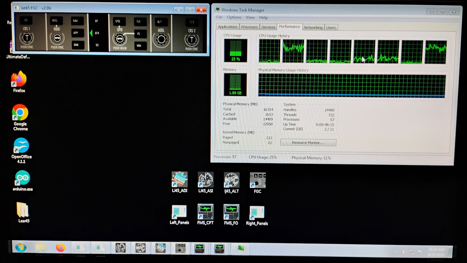
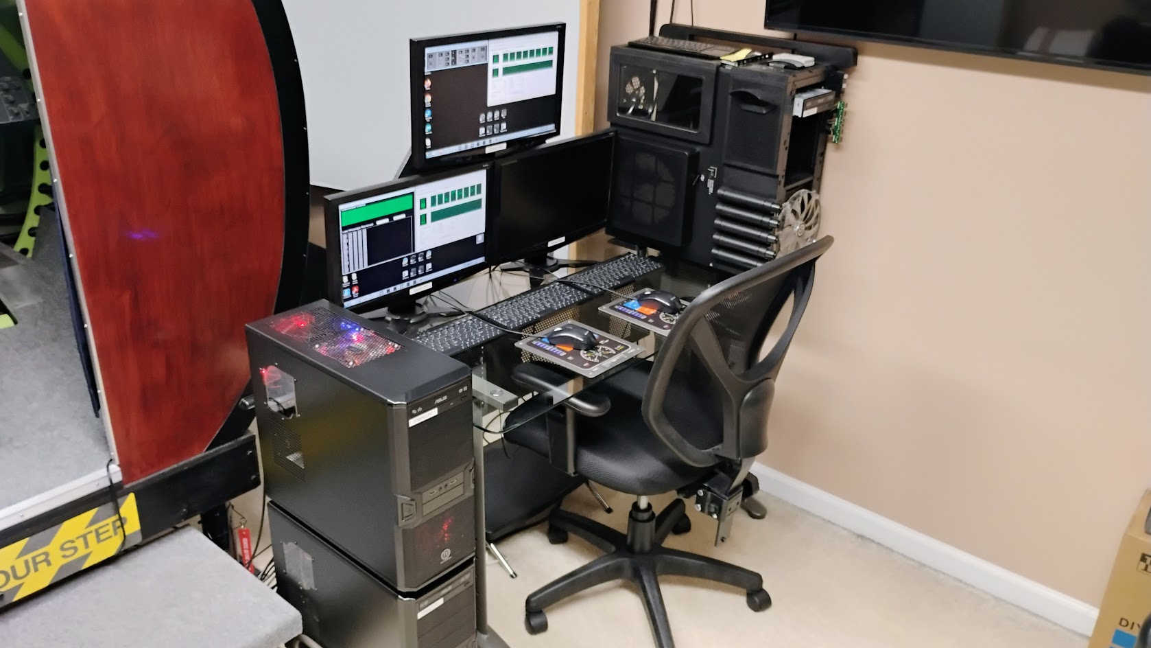
Hey guys, Another quick update on the sim progress. Just recently I put the final touches on the ruder pedal assembly and completed the raised floor deck sections. I added a hydraulic dampener to the system which will help make the rudder control feel heavy and help return the pedals to center. You can read more about the Dual Rudder Pedal Assembly HERE The raised deck system is made up of six pieces. The idea is that if maintenance is required under the decks, only some of the the deck pieces need to be removed rather than the whole thing like previously. You can read more about the Column Crossover and Deck Tutorial HERE Here I have everything installed including the pedal covers. Reworking the raised decks and turning them into removable pieces was a time consuming process, but it's finally complete and behind me now. It looks exactly as it should, one piece, well two pieces, left and right side. This addition will pay off 10 fold in the future! Last but not least, I made a certificate pocket for the Certificate of Aircraft Registration and the Standard Airworthiness Certificate. It a minor detail but important detail. Can't go flying without these documents! You can read more about the Certificate Pocket and Frame HERE I finally feel like I am at a point where I can start making some serious progress, or at least post up more exciting photos of the progress. Like every project worth building, you need to have a solid foundation to build on. Another update soon! Hey guys, Another quick update on the sim progress. Just recently I put the final touches on the ruder pedal assembly and completed the raised floor deck sections. I added a hydraulic dampener to the system which will help make the rudder control feel heavy and help return the pedals to center. You can read more about the Dual Rudder Pedal Assembly HERE The raised deck system is made up of six pieces. The idea is that if maintenance is required under the decks, only some of the the deck pieces need to be removed rather than the whole thing like previously. You can read more about the Column Crossover and Deck Tutorial HERE Here I have everything installed including the pedal covers. Reworking the raised decks and turning them into removable pieces was a time consuming process, but it's finally complete and behind me now. It looks exactly as it should, one piece, well two pieces, left and right side. This addition will pay off 10 fold in the future! Last but not least, I made a certificate pocket for the Certificate of Aircraft Registration and the Standard Airworthiness Certificate. It a minor detail but important detail. Can't go flying without these documents! You can read more about the Certificate Pocket and Frame HERE I finally feel like I am at a point where I can start making some serious progress, or at least post up more exciting photos of the progress. Like every project worth building, you need to have a solid foundation to build on. Another update soon! Hey guys, Just reached another milestone in the progress of assembling L45-002 v2.0! By the way, you might have noticed Shane and I are about at the same point with the reassembly process. You can follow his L45-007 V2.0 Project updates HERE Over the past few weeks I was able to get all the furniture pieces sanded, painted and panels mounted to everything. Now we can all clearly see where I am in the process. My list of things yet to be completed has reduced to several dozen items rather than hundreds it feels like! In the "hot seat" right now, next to be completed is the Standby Compass, v2.0 RMUs, v2.0 EFIS panels and the v2.0 WX Radar panel. Here are a couple photos of what it all looks like so far. And here are a few photos of the backside. All the panels are wired up and ready for wiring harnesses. I am still working on a few minor mounting issues of things like power converters which is why everything you see is currently assembled outside of the shell. (It's much easier to reach and fabricate things while outside the shell.) I also finally have the "Airplane" panel completed and ready to be wired up to the Arduino modules. Last but not least, take note of the dual USB sockets mounted into the MIP. This has been observed in at least one Lear45 (the Lear45 Dugald flew) and we thought in this day and age, it's a must in every cockpit. Getting very close to being able to start creating the wiring harnesses. But first, I have a couple more panels and components to finish developing. Next up, RMUs, EFISs and WX Radar panels. They are all about 50% complete, so once I get started on them again, the progress will be fast. Another update soon! Hey guys, Just reached another milestone in the progress of assembling L45-002 v2.0! By the way, you might have noticed Shane and I are about at the same point with the reassembly process. You can follow his L45-007 V2.0 Project updates HERE Over the past few weeks I was able to get all the furniture pieces sanded, painted and panels mounted to everything. Now we can all clearly see where I am in the process. My list of things yet to be completed has reduced to several dozen items rather than hundreds it feels like! In the "hot seat" right now, next to be completed is the Standby Compass, v2.0 RMUs, v2.0 EFIS panels and the v2.0 WX Radar panel. Here are a couple photos of what it all looks like so far. And here are a few photos of the backside. All the panels are wired up and ready for wiring harnesses. I am still working on a few minor mounting issues of things like power converters which is why everything you see is currently assembled outside of the shell. (It's much easier to reach and fabricate things while outside the shell.) I also finally have the "Airplane" panel completed and ready to be wired up to the Arduino modules. Last but not least, take note of the dual USB sockets mounted into the MIP. This has been observed in at least one Lear45 (the Lear45 Dugald flew) and we thought in this day and age, it's a must in every cockpit. Getting very close to being able to start creating the wiring harnesses. But first, I have a couple more panels and components to finish developing. Next up, RMUs, EFISs and WX Radar panels. They are all about 50% complete, so once I get started on them again, the progress will be fast. Another update soon! I've got to get busy ... you have jumped ahead of me! Looks like I have about 20 switches to wire in my future and add them to the MIP. Looking awesome Ron! I've got to get busy ... you have jumped ahead of me! Looks like I have about 20 switches to wire in my future and add them to the MIP. Looking awesome Ron! Looking goood Ron. Glad to see everything fits! Couple of questions about the Airplane Panel: What MOM switches did you use? They look very low profile, and not easy to accidentally push. Did you have to relieve the back of the Cover Panel? Did you consider adding remote Start and Reset buttons for each PC.? Looking goood Ron. Glad to see everything fits! Couple of questions about the Airplane Panel: What MOM switches did you use? They look very low profile, and not easy to accidentally push. Did you have to relieve the back of the Cover Panel? Did you consider adding remote Start and Reset buttons for each PC.? Thanks guys! It has been a long time coming to get to this point. I am having a blast working on things, adding stuff, adjusting things, etc... Reference the reset buttons, I am using 12mm low profile momentary push buttons with red LEDs. They are used to reset the Arduinos remotely and will also have a flashing indicator light to tell you the status of the Arduino. Jason has programmed a "heartbeat" flash for each one. If the lights are flashing like a heartbeat, all is fine. If the LEDs are solid on or off? You got a problem. I did not have to mill out the back side of the Weight Chart panel cover. The reset buttons are low profile and are no taller than .055" high. The Backer panel for the Left Crew panel is .11" thick so there is plenty of room for the reset buttons without needing to mill anything. Here is a photo of the "Airplane" panel without the Left Crew backer panel surrounding it. Keep in mind the holes for these buttons are drilled directly into the aluminum MIP. I got mine from Aliexpress for around $1 each. You can find the link HERE These reset buttons for the Arduinos are designed to be used as "hot restart" buttons so you can reset a module on the fly without getting up and out of the cockpit. Hopefully if we have an Arduino that freezes up or fails, simply hitting the reset button gets things back on track without disrupting the simulated flight. It would not make sense installing reset buttons for the computers because at that point, if you have to rest the computers, your sim session is OVER and your going to have to get out of the sim to get everything set up again anyway. When ordering your buttons, here are the things you need to insure: Thanks guys! It has been a long time coming to get to this point. I am having a blast working on things, adding stuff, adjusting things, etc... Reference the reset buttons, I am using 12mm low profile momentary push buttons with red LEDs. They are used to reset the Arduinos remotely and will also have a flashing indicator light to tell you the status of the Arduino. Jason has programmed a "heartbeat" flash for each one. If the lights are flashing like a heartbeat, all is fine. If the LEDs are solid on or off? You got a problem. I did not have to mill out the back side of the Weight Chart panel cover. The reset buttons are low profile and are no taller than .055" high. The Backer panel for the Left Crew panel is .11" thick so there is plenty of room for the reset buttons without needing to mill anything. Here is a photo of the "Airplane" panel without the Left Crew backer panel surrounding it. Keep in mind the holes for these buttons are drilled directly into the aluminum MIP. I got mine from Aliexpress for around $1 each. You can find the link HERE These reset buttons for the Arduinos are designed to be used as "hot restart" buttons so you can reset a module on the fly without getting up and out of the cockpit. Hopefully if we have an Arduino that freezes up or fails, simply hitting the reset button gets things back on track without disrupting the simulated flight. It would not make sense installing reset buttons for the computers because at that point, if you have to rest the computers, your sim session is OVER and your going to have to get out of the sim to get everything set up again anyway. When ordering your buttons, here are the things you need to insure: That's a great idea! But, I have to say I have not had much need to reset an Arduino yet. Sometimes I have had issues with some Arduinos not being available on start of the PC, but since I use USB slot cards in this PC instead of USB hubs no more issues. But never the less, nice feature!! That's a great idea! But, I have to say I have not had much need to reset an Arduino yet. Sometimes I have had issues with some Arduinos not being available on start of the PC, but since I use USB slot cards in this PC instead of USB hubs no more issues. But never the less, nice feature!! That's a good suggestion, worthy of a follow up Roel. Instead of sending all USB cables to the USB slot card, maybe I'll just use it for the errant recurring USB Arduino's ? I do have an Arduino that has to be reset everytime. I am living proof that Ron's Reset button not only works with the 'Heartbeat' but has made not going to the nose, to hit the tiny reset button on the Arduino. That's a good suggestion, worthy of a follow up Roel. Instead of sending all USB cables to the USB slot card, maybe I'll just use it for the errant recurring USB Arduino's ? I do have an Arduino that has to be reset everytime. I am living proof that Ron's Reset button not only works with the 'Heartbeat' but has made not going to the nose, to hit the tiny reset button on the Arduino. Well after Roel's excellent suggestion of a pci usb card, I trundled down to Melbourne to purchase some. Well word must have gotten out about Roel's excellent advice, in Melbourne, so I got the last one. Sigh. So I installed it into the computer, a Client, which is giving me the most USB grief. Unfortunately my issues are intermittent, so it didn't help. I have had to look elsewhere for what would cause USB issues. The possible options are ; 1/ old BIOS 2/ Cheap Chinese cable, extension cable and/or powered hub 3/ distance from USB panel to PC 4/ PC USB power, poor quality and EMF, so requires a USB Isolator, between the PC and the USB cables to the Jet45 USB Panels. ( thanking you DonnyRay for this advice ). Here is his recommendation, new. You can buy 2nd hand much cheaper on eBay. https://www.startech.com/en-us/usb-hubs/st7200usbm 5/ USB 3.0 as against USB 2.0 cables.You need to consider distance. USB 2.0, 16 ft. USB 3.0, 6-9ft. Note Ext. cables will extend these lengths but with some degradation. So more testing my end. At least I have more USB ports to use ! Cheers Mark S. Well after Roel's excellent suggestion of a pci usb card, I trundled down to Melbourne to purchase some. Well word must have gotten out about Roel's excellent advice, in Melbourne, so I got the last one. Sigh. So I installed it into the computer, a Client, which is giving me the most USB grief. Unfortunately my issues are intermittent, so it didn't help. I have had to look elsewhere for what would cause USB issues. The possible options are ; 1/ old BIOS 2/ Cheap Chinese cable, extension cable and/or powered hub 3/ distance from USB panel to PC 4/ PC USB power, poor quality and EMF, so requires a USB Isolator, between the PC and the USB cables to the Jet45 USB Panels. ( thanking you DonnyRay for this advice ). Here is his recommendation, new. You can buy 2nd hand much cheaper on eBay. https://www.startech.com/en-us/usb-hubs/st7200usbm 5/ USB 3.0 as against USB 2.0 cables.You need to consider distance. USB 2.0, 16 ft. USB 3.0, 6-9ft. Note Ext. cables will extend these lengths but with some degradation. So more testing my end. At least I have more USB ports to use ! Cheers Mark S. Hey guys, I got another update on the v2.0 progress! To kick things off, it's now official, the v2.0 sim is going to be a Learjet45 XR. I used the CNC and the laser to cut and engrave this badge out of cast plastic. Just a little detail that adds to the overall project. I have the cabin door light switch wired in. What's cool about this lighted switch is if you have shut down the sim and walking away from it thinking that all power has been shut down, if you see this red ring around the switch, power is still being applied to the sim and the last remaining power switches need to be turned off. This switch works just like the real one does. If pressed, the left overhead light comes on in the cockpit so you have a light to get into the cockpit without killing yourself. The cabin door switch can be overridden by turning on the Left Overhead PWM Light switch. Most of my time lately has been spent wiring up all the hardware and things that require either 5 or 12 volt power. To date, I have completed 24 of the 34 wiring diagrams. Here is a look at the current progress in the Avionics Bay. A closer look at one of the Power Management panels. For more detailed information on what's happening in the Avionics Bay, click HERE I found a set of real Lear45 Luminators, also known as map lights! It only took 15 years but finally a set popped up on eBay. Neither one of them worked and both had to be rebuilt and the 28v bulbs replaced with 14v bulbs. I have them temporarily mounted in the sim so that I can test them with the rest of the powered hardware. Additionally, I have installed the USB power socket system. In all there will be 12 USB sockets in the cockpit. This sounds like a lot but it's really just six dual USB sockets. Four mounted on the wings of the MIP, two on each side. Four under the column boots, two on each side. And four in the Center Pedestal, two in the Phone Panel. And two behind the Maintenance Access cover. And this is what the cockpit currently looks like. The most noticeable change is the wire bundles coming in from the Avionics Bay. I have three bundles of wires running in going to the left, the right and down the middle. In a few weeks I should be able to finally say I have all the 12 volt power hardware wired in and tested! Another update soon. Hey guys, I got another update on the v2.0 progress! To kick things off, it's now official, the v2.0 sim is going to be a Learjet45 XR. I used the CNC and the laser to cut and engrave this badge out of cast plastic. Just a little detail that adds to the overall project. I have the cabin door light switch wired in. What's cool about this lighted switch is if you have shut down the sim and walking away from it thinking that all power has been shut down, if you see this red ring around the switch, power is still being applied to the sim and the last remaining power switches need to be turned off. This switch works just like the real one does. If pressed, the left overhead light comes on in the cockpit so you have a light to get into the cockpit without killing yourself. The cabin door switch can be overridden by turning on the Left Overhead PWM Light switch. Most of my time lately has been spent wiring up all the hardware and things that require either 5 or 12 volt power. To date, I have completed 24 of the 34 wiring diagrams. Here is a look at the current progress in the Avionics Bay. A closer look at one of the Power Management panels. For more detailed information on what's happening in the Avionics Bay, click HERE I found a set of real Lear45 Luminators, also known as map lights! It only took 15 years but finally a set popped up on eBay. Neither one of them worked and both had to be rebuilt and the 28v bulbs replaced with 14v bulbs. I have them temporarily mounted in the sim so that I can test them with the rest of the powered hardware. Additionally, I have installed the USB power socket system. In all there will be 12 USB sockets in the cockpit. This sounds like a lot but it's really just six dual USB sockets. Four mounted on the wings of the MIP, two on each side. Four under the column boots, two on each side. And four in the Center Pedestal, two in the Phone Panel. And two behind the Maintenance Access cover. And this is what the cockpit currently looks like. The most noticeable change is the wire bundles coming in from the Avionics Bay. I have three bundles of wires running in going to the left, the right and down the middle. In a few weeks I should be able to finally say I have all the 12 volt power hardware wired in and tested! Another update soon. Hey guys, Over the past three months I have made some significant progress in getting the sim wired up and back together with all the new updates. Starting with nearly a miles worth of wiring! I took the extra steps to label both ends of each wiring harness. Spend some time now to save time and headaches down the road. The wire/cable management frame works very well. I am able to open each of the pullout panels without issue, even with all the wires installed. A closer look at the left side panels. And a closer look at the right side panels. The back side of the left upper pullout panel. As neat as I am capable of making things. And the back side of the right upper panel. This side also has two 16 channel relay cards which is why you see so many red power lines. I sill have to add several powered USB hubs and all the USB cables to each of the Arduinos. But getting closer! Inside the cockpit, I have also made significant progress! Starting with adding the TQ Pedestal. Sounds easy, but it took a little time routing all the wiring harnesses in the right direction. And here I have the MIP Tower, MIP Backer and the four LCD screens installed. A view we don't ever see of some of the bracket work. All this stuff will just fit together perfectly because of countless hours of planning and test fitting prior to final assembly. The MIP and Glareshield bolted right in without any issues. The panels also went in without a hitch. The Gear/HYD panel was the last to be installed. I used towels to help protect the panels from each other during assembly. There will be plenty of time to beat things up, it just does not need to happen while putting things together. FINALLY! It has been a long time coming and a lot of work to get back to this point. When I first took the MIP out of the sim back in 2018, I never thought it would take seven years to get it back in! The viewing angles of the new center screen(s) solution is second to only the real thing. The First Officer's side looks just as good. (I have the flood light on.) The viewing angles of the FMS/CDUs are also very good! Couldn't be happier with the five inch LCD screens for the CDUs. Before I show you the next set of photos, I have to point out that my phone struggles with dark photos with bright lights mixed in. This photo is close to what my naked eyes see when looking at the Display Units. Crisp, clean and full of color. All the backlighting works perfectly after some adjustments and everything is on it's proper LCU (Light Control Unit) channel. (Terrible whitewash from all the LCD screens in these photos) Here I have the flood light back on. I still have to make a set of EFIS panels and a TQ light plate among a few other things. At this point, the reassembly with all the changes is well underway. Now I can pick and choose what I want to work on, there is still no shortage of projects! Another area of the build that I just started working on is the computers. To set a baseline of where I was with V1.0 when I took things down in 2018, I was using three computers. All three computers were running Windows7 Pro. The Server was an i7 2600k machine with 16gb of ram. The main video card was a GTX1070 with 8gb of ram. The two Clients were i3 machines with 8gb of ram. It does not sound like much but in 2011 when I built these for the v1.0 sim to work with FSX/P3D, things worked fairly well. (Keep in mind that along the way I added a computer and in 2017 I added the GTX1070 graphics card.) Today, the main goal for me is to get up and running as quickly and efficiently as possible to start testing Jet45. So please don't take the information you read here as the best way to move forward at this point in time. In my case, I have a lot of good computer hardware that can be recycled into the two client machines. I have decided to move forward with the same three computer setup, the Server computer and two Client machines. The two client machines have been updated to i7 2600k CPUs and 16gb of ram. They both use Win7 Pro. Here is a screen shot of the Client-1 machine running the Jet45 Server and it's assigned modules. The CPU usage is hovering around 29%. And this is a screen shot of Client-2 running it's assigned modules. The CPU usage is around 27%. Both Client machines are pretty evenly balanced and I don't plan to add much more to them. Basically, all I am asking of them is to run Jet45 and the Standby Gauges. Last but not least, I will be upgrading the Server to an i9 machine with at least 64gb of ram. It will be a Win11 Pro machine. I have about half of the components needed to build this machine but holding off until I complete a few other projects. My "Instructor Station" has not changed much except for whats inside the computer cases. I have nicknamed this temporary setup "SevenElevenPro". It should serve it's purpose. So far so good. I consider this a temporary solution to move forward with testing. This is not the way you should set up your computers unless you are in a similar situation as I am in. Later on I will replace the two i7 Win7 machines with a couple mini i9 Win11 machines. Another update coming soon! Hey guys, Over the past three months I have made some significant progress in getting the sim wired up and back together with all the new updates. Starting with nearly a miles worth of wiring! I took the extra steps to label both ends of each wiring harness. Spend some time now to save time and headaches down the road. The wire/cable management frame works very well. I am able to open each of the pullout panels without issue, even with all the wires installed. A closer look at the left side panels. And a closer look at the right side panels. The back side of the left upper pullout panel. As neat as I am capable of making things. And the back side of the right upper panel. This side also has two 16 channel relay cards which is why you see so many red power lines. I sill have to add several powered USB hubs and all the USB cables to each of the Arduinos. But getting closer! Inside the cockpit, I have also made significant progress! Starting with adding the TQ Pedestal. Sounds easy, but it took a little time routing all the wiring harnesses in the right direction. And here I have the MIP Tower, MIP Backer and the four LCD screens installed. A view we don't ever see of some of the bracket work. All this stuff will just fit together perfectly because of countless hours of planning and test fitting prior to final assembly. The MIP and Glareshield bolted right in without any issues. The panels also went in without a hitch. The Gear/HYD panel was the last to be installed. I used towels to help protect the panels from each other during assembly. There will be plenty of time to beat things up, it just does not need to happen while putting things together. FINALLY! It has been a long time coming and a lot of work to get back to this point. When I first took the MIP out of the sim back in 2018, I never thought it would take seven years to get it back in! The viewing angles of the new center screen(s) solution is second to only the real thing. The First Officer's side looks just as good. (I have the flood light on.) The viewing angles of the FMS/CDUs are also very good! Couldn't be happier with the five inch LCD screens for the CDUs. Before I show you the next set of photos, I have to point out that my phone struggles with dark photos with bright lights mixed in. This photo is close to what my naked eyes see when looking at the Display Units. Crisp, clean and full of color. All the backlighting works perfectly after some adjustments and everything is on it's proper LCU (Light Control Unit) channel. (Terrible whitewash from all the LCD screens in these photos) Here I have the flood light back on. I still have to make a set of EFIS panels and a TQ light plate among a few other things. At this point, the reassembly with all the changes is well underway. Now I can pick and choose what I want to work on, there is still no shortage of projects! Another area of the build that I just started working on is the computers. To set a baseline of where I was with V1.0 when I took things down in 2018, I was using three computers. All three computers were running Windows7 Pro. The Server was an i7 2600k machine with 16gb of ram. The main video card was a GTX1070 with 8gb of ram. The two Clients were i3 machines with 8gb of ram. It does not sound like much but in 2011 when I built these for the v1.0 sim to work with FSX/P3D, things worked fairly well. (Keep in mind that along the way I added a computer and in 2017 I added the GTX1070 graphics card.) Today, the main goal for me is to get up and running as quickly and efficiently as possible to start testing Jet45. So please don't take the information you read here as the best way to move forward at this point in time. In my case, I have a lot of good computer hardware that can be recycled into the two client machines. I have decided to move forward with the same three computer setup, the Server computer and two Client machines. The two client machines have been updated to i7 2600k CPUs and 16gb of ram. They both use Win7 Pro. Here is a screen shot of the Client-1 machine running the Jet45 Server and it's assigned modules. The CPU usage is hovering around 29%. And this is a screen shot of Client-2 running it's assigned modules. The CPU usage is around 27%. Both Client machines are pretty evenly balanced and I don't plan to add much more to them. Basically, all I am asking of them is to run Jet45 and the Standby Gauges. Last but not least, I will be upgrading the Server to an i9 machine with at least 64gb of ram. It will be a Win11 Pro machine. I have about half of the components needed to build this machine but holding off until I complete a few other projects. My "Instructor Station" has not changed much except for whats inside the computer cases. I have nicknamed this temporary setup "SevenElevenPro". It should serve it's purpose. So far so good. I consider this a temporary solution to move forward with testing. This is not the way you should set up your computers unless you are in a similar situation as I am in. Later on I will replace the two i7 Win7 machines with a couple mini i9 Win11 machines. Another update coming soon!Project45 Flagship L45-002 Sim!
![]()


![]()


![]()
![]()
![]()

![]()
![]()
![]()
![]()
![]()

Project45 Flagship L45-002 Sim!
![]()
![]()
![]()
![]()
![]()
![]()
![]()
![]()
![]()
![]()