


Hey guys, About six weeks ago Shane and I were getting ready to start wiring up our sims and it hit me, we really need wiring diagrams to cover everything outside of the Jet45 Modules to insure we are on the same page with everything. A lot of the items we planned on building into our sims were fairly easy to figure out, but there are a handful of areas that require some thought and it would be really easy for several guys to arrive at the same outcome while taking different paths. This is a perfect recipe for disaster when it comes to helping one another out with trouble shooting. To address this issue, I have drawn up 30 wiring diagrams that cover nearly all of the wiring elements that Shane and I have planned outside of the Jet45 AAS and Systems software. This way we are all but guaranteed that our sims will be as close to identical as possible and trouble shooting potential issues will be a breeze. Look at these wiring diagrams as "par for the course". You don't have to include everything and you can certainly add to them if you like. For me personally, I can't think of anything else I would like to add to them after several years of thinking about what should and needs to be included in order to achieve the level of simulation several of us have in mind. You can find the latest version of the Jet45AAS System Modules with the wiring diagrams HERE If you have not done so yet, take a few minutes to look over some of the wiring diagrams. You will find that some of them are fairly easy to follow and only really serve as a "power flow" map to that particular piece of hardware. And other wiring diagrams are a little more complex, like the overhead lights and Pack Air. In all cases where things can be considered a little more complex, I bench tested the wiring to insure there were no issues. I actually found a couple things that I initially thought should work fine, but only discovered that it needed tweaking during the bench testing. A good example is the Left overhead light bench test. But before we can cover this in detail, you first have to be aware of how the overhead lights work in the real Lear45 and the easiest way to do that is to refer to real world manuals. If you are not aware, the OVHD lights are a little more complex than what you might think. The other thing that you have to be aware of is I have simplified the way our sims will receive power compared to the real Lear45, so if you are following along in the manuals, you might see discrepancies, but for simulation purposes, these wiring diagrams will work fine. LEFT OVERHEAD LIGHT OPERATION: The Left and Right cockpit overhead lights receive power from the R HOT BUS. They are also considered the emergency lighting in the cockpit and have to be manually selected by the pilots. In the real Lear45, the overhead lights will remain illuminated as long as the main batteries have power. In our sims, they will remain illuminated as long as the R Power supply is working. (This is an example of a discrepancy) The Right overhead light can only be controlled from the R OVHD LTS switch on the FO Crew panel, therefor, it is not necessary to talk about it's function in detail. However, the Left Overhead light can be controlled via a switch at the cabin door, the cabin door "closed" pin switch and the L OVHD LTS switch on the Left Crew panel. This photo shows the Left overhead light in a cold and dark state, no power in the plane with the exception of the HOT BUSES and the cockpit light switch at the cabin door is off as well as the pot switch in the cockpit. Here the cabin door is open (meaning the cabin door pin switch is closed) and the cockpit light switch at the cabin door is turned ON. The switch at the cabin door is so that the crew can flip a switch at the door and immediately light up the cockpit to keep from bumping into things while trying to get into the cockpit. We can simulate this by adding a switch just outside of the cockpit on the rear wall if you don't have a cabin section. Here we have to imagine sitting in the cockpit with the switch at the cabin door ON but now the cabin door is closed. This is important because the whole reason behind this hardware logic is to keep someone from flipping the cabin switch ON in flight and blinding the pilots! With a quick turn of the L OVHD LTS switch, you are no longer sitting in the dark. In other words, only the pilots have control of what lights are turned on in the cockpit with the cabin door closed. You can't see it in this photo, but the pot has been turned up to light up the WEMAC again. This wiring logic is designed for two main purposes, to provide light in the cockpit from the cabin door when first entering the aircraft and to keep folks in the cabin from blinding the pilots while in flight by selecting that switch at the cabin door. What this wiring logic does not do is protect itself from accidentally leaving the switches in the cockpit turned on. If those light switches are left on, eventually the batteries will drain because remember, the cockpit overhead lighting is on the R HOT BUS. However, if the light switches in the cockpit are off and the cabin door switch is on, once the cabin door is closed (cabin door pin is open), the cockpit overhead lights will turn off. If you now or ever plan to build a short cabin section for your sim, this is something that you will want to include in your sim. One other thing that you will want to do is upgrade you bulbs. If you have acquired real WEMAC lights, most likely they came with 28v bulbs which you have to change out to 12v bulbs. While you are at it, go ahead and switch to an LED version. Depending on which WEMAC lights you have, you need to be aware of how tall your replacement LED bulbs are. Also make sure you look for warm white. The light in the photos above are with the new LED bulb you see here. And that's it on how to turn a overhead light bulb on! I don't plan on giving a play by play on all the wiring diagrams but this one was interesting to me and it also helps illustrate the power of a wiring diagram. In other Avionics Bay related news, I have designed and built up a couple service modules. They will be mounted on the Avionics bay bulkhead. The first one is for the Display Unit cooling fans and Avionics Bay lights. Each Display Unit gets it's own fan where before, we only had a left fan and a right fan. Two fans worked fine but four fans will work great! It's not a matter of trying to keep something cool, although the fans and placement of them helps to keep the air moving. What it is really about is the sound of the fans. Maciej gets credit for this idea and that is if we add variable pots to each DU fan, we can fine tune the fans to achieve perfect "avionics noise". Once they are set, you never touch them again. This replaces the idea of buying two or more different types of fans. The second half of this first Service module is for the Avionics Bay lights. I will have what I call bay lights that will be cool white to help work on things and Flood lights that will be red that I can leave on while in simulation. The pots of course allow you to adjust how bright you want or need the lights. This service module will be one of the first things I add in the Avionics Bay so that I can see what I am doing! The Environmental Cooling Service Module serves more of a wiring hub for the L&R blowers, relays and variable pots. Not at all needed, but I also added L&R Blower Master switches. These switches and the Pack Air and Hi Flow pots will all be left ON, set and left alone. Why do we need pots for the blowers you might ask? The Pack Air pot will be set at 6v and the HI FLOW pot will be set at 9v. This will help simulate the sound of the HI FLOW switch being selected and also provide additional airflow from the left and right blowers. For more details on how to wire up the Environmental Cooling system, see the wiring diagrams. More updates on the Avionics Bay and the wiring soon! Hey guys, About six weeks ago Shane and I were getting ready to start wiring up our sims and it hit me, we really need wiring diagrams to cover everything outside of the Jet45 Modules to insure we are on the same page with everything. A lot of the items we planned on building into our sims were fairly easy to figure out, but there are a handful of areas that require some thought and it would be really easy for several guys to arrive at the same outcome while taking different paths. This is a perfect recipe for disaster when it comes to helping one another out with trouble shooting. To address this issue, I have drawn up 30 wiring diagrams that cover nearly all of the wiring elements that Shane and I have planned outside of the Jet45 AAS and Systems software. This way we are all but guaranteed that our sims will be as close to identical as possible and trouble shooting potential issues will be a breeze. Look at these wiring diagrams as "par for the course". You don't have to include everything and you can certainly add to them if you like. For me personally, I can't think of anything else I would like to add to them after several years of thinking about what should and needs to be included in order to achieve the level of simulation several of us have in mind. You can find the latest version of the Jet45AAS System Modules with the wiring diagrams HERE If you have not done so yet, take a few minutes to look over some of the wiring diagrams. You will find that some of them are fairly easy to follow and only really serve as a "power flow" map to that particular piece of hardware. And other wiring diagrams are a little more complex, like the overhead lights and Pack Air. In all cases where things can be considered a little more complex, I bench tested the wiring to insure there were no issues. I actually found a couple things that I initially thought should work fine, but only discovered that it needed tweaking during the bench testing. A good example is the Left overhead light bench test. But before we can cover this in detail, you first have to be aware of how the overhead lights work in the real Lear45 and the easiest way to do that is to refer to real world manuals. If you are not aware, the OVHD lights are a little more complex than what you might think. The other thing that you have to be aware of is I have simplified the way our sims will receive power compared to the real Lear45, so if you are following along in the manuals, you might see discrepancies, but for simulation purposes, these wiring diagrams will work fine. LEFT OVERHEAD LIGHT OPERATION: The Left and Right cockpit overhead lights receive power from the R HOT BUS. They are also considered the emergency lighting in the cockpit and have to be manually selected by the pilots. In the real Lear45, the overhead lights will remain illuminated as long as the main batteries have power. In our sims, they will remain illuminated as long as the R Power supply is working. (This is an example of a discrepancy) The Right overhead light can only be controlled from the R OVHD LTS switch on the FO Crew panel, therefor, it is not necessary to talk about it's function in detail. However, the Left Overhead light can be controlled via a switch at the cabin door, the cabin door "closed" pin switch and the L OVHD LTS switch on the Left Crew panel. This photo shows the Left overhead light in a cold and dark state, no power in the plane with the exception of the HOT BUSES and the cockpit light switch at the cabin door is off as well as the pot switch in the cockpit. Here the cabin door is open (meaning the cabin door pin switch is closed) and the cockpit light switch at the cabin door is turned ON. The switch at the cabin door is so that the crew can flip a switch at the door and immediately light up the cockpit to keep from bumping into things while trying to get into the cockpit. We can simulate this by adding a switch just outside of the cockpit on the rear wall if you don't have a cabin section. Here we have to imagine sitting in the cockpit with the switch at the cabin door ON but now the cabin door is closed. This is important because the whole reason behind this hardware logic is to keep someone from flipping the cabin switch ON in flight and blinding the pilots! With a quick turn of the L OVHD LTS switch, you are no longer sitting in the dark. In other words, only the pilots have control of what lights are turned on in the cockpit with the cabin door closed. You can't see it in this photo, but the pot has been turned up to light up the WEMAC again. This wiring logic is designed for two main purposes, to provide light in the cockpit from the cabin door when first entering the aircraft and to keep folks in the cabin from blinding the pilots while in flight by selecting that switch at the cabin door. What this wiring logic does not do is protect itself from accidentally leaving the switches in the cockpit turned on. If those light switches are left on, eventually the batteries will drain because remember, the cockpit overhead lighting is on the R HOT BUS. However, if the light switches in the cockpit are off and the cabin door switch is on, once the cabin door is closed (cabin door pin is open), the cockpit overhead lights will turn off. If you now or ever plan to build a short cabin section for your sim, this is something that you will want to include in your sim. One other thing that you will want to do is upgrade you bulbs. If you have acquired real WEMAC lights, most likely they came with 28v bulbs which you have to change out to 12v bulbs. While you are at it, go ahead and switch to an LED version. Depending on which WEMAC lights you have, you need to be aware of how tall your replacement LED bulbs are. Also make sure you look for warm white. The light in the photos above are with the new LED bulb you see here. And that's it on how to turn a overhead light bulb on! I don't plan on giving a play by play on all the wiring diagrams but this one was interesting to me and it also helps illustrate the power of a wiring diagram. In other Avionics Bay related news, I have designed and built up a couple service modules. They will be mounted on the Avionics bay bulkhead. The first one is for the Display Unit cooling fans and Avionics Bay lights. Each Display Unit gets it's own fan where before, we only had a left fan and a right fan. Two fans worked fine but four fans will work great! It's not a matter of trying to keep something cool, although the fans and placement of them helps to keep the air moving. What it is really about is the sound of the fans. Maciej gets credit for this idea and that is if we add variable pots to each DU fan, we can fine tune the fans to achieve perfect "avionics noise". Once they are set, you never touch them again. This replaces the idea of buying two or more different types of fans. The second half of this first Service module is for the Avionics Bay lights. I will have what I call bay lights that will be cool white to help work on things and Flood lights that will be red that I can leave on while in simulation. The pots of course allow you to adjust how bright you want or need the lights. This service module will be one of the first things I add in the Avionics Bay so that I can see what I am doing! The Environmental Cooling Service Module serves more of a wiring hub for the L&R blowers, relays and variable pots. Not at all needed, but I also added L&R Blower Master switches. These switches and the Pack Air and Hi Flow pots will all be left ON, set and left alone. Why do we need pots for the blowers you might ask? The Pack Air pot will be set at 6v and the HI FLOW pot will be set at 9v. This will help simulate the sound of the HI FLOW switch being selected and also provide additional airflow from the left and right blowers. For more details on how to wire up the Environmental Cooling system, see the wiring diagrams. More updates on the Avionics Bay and the wiring soon! Hey guys, We have been busy working on several aspects of the sim, most importantly an all new CDU/FMS UNS1. But in between waiting on development aspects and parts to arrive, progress is being made within the Avionics Bay. When we first started the overhaul of the Avionics Bay, the ideas we had planned for v2 were not as plentiful as we have today. Even since the last post made in January, a few more good ideas have made their way into the sim! The main idea is to make all the "dirty" modifications now prior to all the wiring. This way we won't have to pull anything out to make these future changes. Here are a couple more updates that have been completed recently. First, the addition of two stand alone hot buses. Each side of the aircraft's power supply has a dedicated hot bus. The question is where to mount them? Turns out we have plenty of space on the back side of the lower power panels. However, the bus terminals I chose needed a little modification. The positive and negative terminal post were gigantic, 1/4" bolts and way too long. I opted to drop them down to size 10 bolts and much shorter. This way there will be plenty of clearance on the back side of the power panels when latched to the bulkhead. The other thing we added to the rear side of the power panels were the 12v to 5v DC converters. We need five in total. L LCU, R LCU, PED LCU, L CB Panel LCU and the R CB Panel LCU. To even things out, I added one more that will be a Spare/Test 5v DC converter. Here is an overview of the new Hot Buses and DC converters mounted and in place. All that needs to be done now is reinstall the panels and start wiring! The next thing that was recently added was a sub floor in the base frame under the Avionics Bay floor. Shane and I thought this would be a necessary modification in preparation for the future v2 Dual Pedal System we have designed. The way the new pedal system is designed has the cross connection rod, bell cranks and rudder dampeners mounted under the sub floor. This sub floor hatch will provide easier access to these future components! After getting it drawn out and proven it was possible to add the hatch, it was time to make it happen. The hatch dimension are 12" x 24". The easiest way to go about cutting the opening in the sub floor was to create a jig. Here it is sitting in the pocket between the shell base frames. And here is the hatch sitting in the jig pocket. It's just a rectangle but it can be tricky cutting a perfectly square rectangle slightly under sized to fit into the pocket! In these photos, I already have the latch pockets cut into the hatch. I was able to make these latch pockets with the CNC. Here is the hatch sitting on top of the jig. After the hole is cut in the sub floor, aluminum trim pieces will be added on all four side to create edges for the hatch to sit on. The easiest way to insure the holes are even and straight is to include them on the jig. Here I have the aluminum strips lined up on the jig transferring the holes. A fresh coat of paint and installation of the latches completes the hatch. Here is a close up of one of the latches. I have them counter sunk into the face of the hatch. Again, easy to make happen if you have access to a CNC. Now the fun part, cutting the hatch hole in the sub floor. First, I used the jig to mark guide lines to jigsaw out the majority of the hole. The really fun part was routing the hole out upside down which I don't recommend. The safer and easier way would be to unbolt the shell frame from the sub floor and move the shell frame out of the way. In this case, the guide jig would be under the sub floor. But because I did it upside down, the guide jig was on top of the sub floor. What you are left with is a nice clean hatch hole! You can see how easy it will be to gain access to the future sub floor pedal assembly. More fun! Here I have the jig mounted to the under side of the newly cut hatch hole. Now I can drill the holes for the aluminum strips using the guide holes in the jig. I must say this is not a view we have ever seen before! I will have some follow up photos of the Sub Floor Hatch in place when it is fully complete. I need to do some edge and trim painting first. Last but not least, Shane had a good idea of working out the final details with the blower and ventilation system, also known as the Pack Air system. A good idea to figure out now if there are any additional "dirty" modification needed to the Avionics Bay bulkhead. As it turns out, not much to modify to the bulkhead itself, but it did get me to spending a little time on the ventilation and Pack Air system. To recap, what we are planning on modeling is a simplified version of the Pack Air System. When the Pack Air Switch is selected, air will blow through the six vents in the cockpit, three vents on each side via two blower motors, one on each side. If the Pack Air switch is selected, the HI-FLOW switch will also be available. If the HI FLOW switch is selected, the blower motors will step up a notch simulating the HI-FLOW switch being selected. If the Pack Air switch is not selected, the HI-FLOW switch will be Inop. Besides simulating a simplified version of the Pack Air system, the goal is to pipe in fresh air from two outside intakes mounted at the front lower end of the shell while the four Avionics fans are pulling stale air out of the cockpit. Additionally, we can add a stand alone space heater that can be controlled by the Manual Temp switch for you guys in colder environments. (More on that later) The first part of the problem to overcome was what tubing to use. The bigger the better when it comes to air volume. But we wanted something that fits through the holes in the shell frames and fits on the smallest scoop inlets also known as plenums. The hose also needs to be flexible and smooth on the inside walls to keep the air moving forward as easy as possible. What I found that checks most if not all of the boxes was 3/4" I.D. Fountain Tubing! At $20 for 20 feet, two bundles is plenty to reach all six vents from the blowers. And the 3/4" I.D. is perfect for the air inlets of a couple plenums I have. Keep in mind that the inlets on the Lear45 air vents vary depending which ones you are talking about. In all cases, the real air vents in the Lear45 are bigger than the one I have pictured here. The problem that we all face is finding authentic aviation air vents, let alone ones that came out of or for a Lera45. If you can find the real things, you will end up paying a very high price for them unless your seller has not a clue what they have. At this point, I have six aviation air vents that will work but none are from a Lear45. However, they will work! The next problem was finding adapter fittings that mount to the 3" and 4" blower outlets and then to the three 3/4" tubes. Two issues we face, splitting the blower outlet three ways and reducing the outlets from 3" or 4" diameter to 3/4" I.D. After a few hours of search the world wide web, turns out, there is no such thing. The solution to the problem is to just make the fittings from scratch! If you are wondering why there are two different sizes, I have two 3" blowers and Shane has two 4" blowers. They are both 12 volts and rated to push about the same amount of air. The question is will they both be as efficient or will one be better than the other? We will see. I used PVC reducer fittings to plug the air hoses into the adapter. But they needed to be honed out slightly. Additionally, the hoses need to be split (cut) to slide into the pvc fittings. Here I have the new adapter plates assembled and ready to be installed on the 3" blowers. And here I have my 3" blowers built up and ready to install under the Avionics Bay floor on the lower bulkhead. I have included a mounting plate with rubber shims to dampen any noise or vibrations that might transfer through the shell frame. One thing about blowers like these is they can be on the loud side, but we believe it's manageable with a couple tricks like this. More on ways to control excessive blower noise later. A close up of the rubber shock shims. These four mounting points attach directly to the Avionics Bay floor supports. Last but not least, a close up shot of the custom made adapter for the 3" blowers. If this works as good as it looks, we will be good! I am excited to get them mounted up. Initial testing proves it blows air through the tubes but not as strong as you might expect. I found that the longer the tubing, the less airflow volume at the airvent outlets. After all, this is a simplified simulated system that adds some functionality but is not perfect. Later down the road this may be an area that we revisit, but for now, I am happy with it. If anyone has ideas or suggestions, please share! My findings were that the ankle outlets will have less than 2 feet of tubing and have satisfactory air flow. The elbow outlets will be less than four feet long and I found the airflow to be okay. The problem is the overhead vents. If we run the tubing down the side walls of the airframe up the back and then across the top, we are near 12 feet of tubing and the airflow is present but less than desirable. But there is a short cut route! I found it is possible to route the overhead tubing up the center windscreen post cutting over four feet of length out. This will certainly increase the airflow to the overhead outlets. And as Shane pointed out to me, those vents are right there at your head and you can definitely feel them blowing your hair around. Well that's a problem for me, you have to have hair to blow hair! LOL We have many other aspects of the Avionics Bay updates in the works and hopefully we will have them all complete in the next month or two. More updates to come! Hey guys, We have been busy working on several aspects of the sim, most importantly an all new CDU/FMS UNS1. But in between waiting on development aspects and parts to arrive, progress is being made within the Avionics Bay. When we first started the overhaul of the Avionics Bay, the ideas we had planned for v2 were not as plentiful as we have today. Even since the last post made in January, a few more good ideas have made their way into the sim! The main idea is to make all the "dirty" modifications now prior to all the wiring. This way we won't have to pull anything out to make these future changes. Here are a couple more updates that have been completed recently. First, the addition of two stand alone hot buses. Each side of the aircraft's power supply has a dedicated hot bus. The question is where to mount them? Turns out we have plenty of space on the back side of the lower power panels. However, the bus terminals I chose needed a little modification. The positive and negative terminal post were gigantic, 1/4" bolts and way too long. I opted to drop them down to size 10 bolts and much shorter. This way there will be plenty of clearance on the back side of the power panels when latched to the bulkhead. The other thing we added to the rear side of the power panels were the 12v to 5v DC converters. We need five in total. L LCU, R LCU, PED LCU, L CB Panel LCU and the R CB Panel LCU. To even things out, I added one more that will be a Spare/Test 5v DC converter. Here is an overview of the new Hot Buses and DC converters mounted and in place. All that needs to be done now is reinstall the panels and start wiring! The next thing that was recently added was a sub floor in the base frame under the Avionics Bay floor. Shane and I thought this would be a necessary modification in preparation for the future v2 Dual Pedal System we have designed. The way the new pedal system is designed has the cross connection rod, bell cranks and rudder dampeners mounted under the sub floor. This sub floor hatch will provide easier access to these future components! After getting it drawn out and proven it was possible to add the hatch, it was time to make it happen. The hatch dimension are 12" x 24". The easiest way to go about cutting the opening in the sub floor was to create a jig. Here it is sitting in the pocket between the shell base frames. And here is the hatch sitting in the jig pocket. It's just a rectangle but it can be tricky cutting a perfectly square rectangle slightly under sized to fit into the pocket! In these photos, I already have the latch pockets cut into the hatch. I was able to make these latch pockets with the CNC. Here is the hatch sitting on top of the jig. After the hole is cut in the sub floor, aluminum trim pieces will be added on all four side to create edges for the hatch to sit on. The easiest way to insure the holes are even and straight is to include them on the jig. Here I have the aluminum strips lined up on the jig transferring the holes. A fresh coat of paint and installation of the latches completes the hatch. Here is a close up of one of the latches. I have them counter sunk into the face of the hatch. Again, easy to make happen if you have access to a CNC. Now the fun part, cutting the hatch hole in the sub floor. First, I used the jig to mark guide lines to jigsaw out the majority of the hole. The really fun part was routing the hole out upside down which I don't recommend. The safer and easier way would be to unbolt the shell frame from the sub floor and move the shell frame out of the way. In this case, the guide jig would be under the sub floor. But because I did it upside down, the guide jig was on top of the sub floor. What you are left with is a nice clean hatch hole! You can see how easy it will be to gain access to the future sub floor pedal assembly. More fun! Here I have the jig mounted to the under side of the newly cut hatch hole. Now I can drill the holes for the aluminum strips using the guide holes in the jig. I must say this is not a view we have ever seen before! I will have some follow up photos of the Sub Floor Hatch in place when it is fully complete. I need to do some edge and trim painting first. Last but not least, Shane had a good idea of working out the final details with the blower and ventilation system, also known as the Pack Air system. A good idea to figure out now if there are any additional "dirty" modification needed to the Avionics Bay bulkhead. As it turns out, not much to modify to the bulkhead itself, but it did get me to spending a little time on the ventilation and Pack Air system. To recap, what we are planning on modeling is a simplified version of the Pack Air System. When the Pack Air Switch is selected, air will blow through the six vents in the cockpit, three vents on each side via two blower motors, one on each side. If the Pack Air switch is selected, the HI-FLOW switch will also be available. If the HI FLOW switch is selected, the blower motors will step up a notch simulating the HI-FLOW switch being selected. If the Pack Air switch is not selected, the HI-FLOW switch will be Inop. Besides simulating a simplified version of the Pack Air system, the goal is to pipe in fresh air from two outside intakes mounted at the front lower end of the shell while the four Avionics fans are pulling stale air out of the cockpit. Additionally, we can add a stand alone space heater that can be controlled by the Manual Temp switch for you guys in colder environments. (More on that later) The first part of the problem to overcome was what tubing to use. The bigger the better when it comes to air volume. But we wanted something that fits through the holes in the shell frames and fits on the smallest scoop inlets also known as plenums. The hose also needs to be flexible and smooth on the inside walls to keep the air moving forward as easy as possible. What I found that checks most if not all of the boxes was 3/4" I.D. Fountain Tubing! At $20 for 20 feet, two bundles is plenty to reach all six vents from the blowers. And the 3/4" I.D. is perfect for the air inlets of a couple plenums I have. Keep in mind that the inlets on the Lear45 air vents vary depending which ones you are talking about. In all cases, the real air vents in the Lear45 are bigger than the one I have pictured here. The problem that we all face is finding authentic aviation air vents, let alone ones that came out of or for a Lera45. If you can find the real things, you will end up paying a very high price for them unless your seller has not a clue what they have. At this point, I have six aviation air vents that will work but none are from a Lear45. However, they will work! The next problem was finding adapter fittings that mount to the 3" and 4" blower outlets and then to the three 3/4" tubes. Two issues we face, splitting the blower outlet three ways and reducing the outlets from 3" or 4" diameter to 3/4" I.D. After a few hours of search the world wide web, turns out, there is no such thing. The solution to the problem is to just make the fittings from scratch! If you are wondering why there are two different sizes, I have two 3" blowers and Shane has two 4" blowers. They are both 12 volts and rated to push about the same amount of air. The question is will they both be as efficient or will one be better than the other? We will see. I used PVC reducer fittings to plug the air hoses into the adapter. But they needed to be honed out slightly. Additionally, the hoses need to be split (cut) to slide into the pvc fittings. Here I have the new adapter plates assembled and ready to be installed on the 3" blowers. And here I have my 3" blowers built up and ready to install under the Avionics Bay floor on the lower bulkhead. I have included a mounting plate with rubber shims to dampen any noise or vibrations that might transfer through the shell frame. One thing about blowers like these is they can be on the loud side, but we believe it's manageable with a couple tricks like this. More on ways to control excessive blower noise later. A close up of the rubber shock shims. These four mounting points attach directly to the Avionics Bay floor supports. Last but not least, a close up shot of the custom made adapter for the 3" blowers. If this works as good as it looks, we will be good! I am excited to get them mounted up. Initial testing proves it blows air through the tubes but not as strong as you might expect. I found that the longer the tubing, the less airflow volume at the airvent outlets. After all, this is a simplified simulated system that adds some functionality but is not perfect. Later down the road this may be an area that we revisit, but for now, I am happy with it. If anyone has ideas or suggestions, please share! My findings were that the ankle outlets will have less than 2 feet of tubing and have satisfactory air flow. The elbow outlets will be less than four feet long and I found the airflow to be okay. The problem is the overhead vents. If we run the tubing down the side walls of the airframe up the back and then across the top, we are near 12 feet of tubing and the airflow is present but less than desirable. But there is a short cut route! I found it is possible to route the overhead tubing up the center windscreen post cutting over four feet of length out. This will certainly increase the airflow to the overhead outlets. And as Shane pointed out to me, those vents are right there at your head and you can definitely feel them blowing your hair around. Well that's a problem for me, you have to have hair to blow hair! LOL We have many other aspects of the Avionics Bay updates in the works and hopefully we will have them all complete in the next month or two. More updates to come! Hi Ron, Nice work on the air distribution chamber. Did you look at food-grade hoses? They have smoother inside walls that dont trap food (or air). Less turbulence, more airflow? I use them on my machinery as the mill and lathe make hard spiral swarf. This swarf constantly gets stuck creating blockages in conventional vacuum spiral tube but slips through food-grade tube. It is available in many sizes. Not as cheap as what you have, but worth considering. Hi Ron, Nice work on the air distribution chamber. Did you look at food-grade hoses? They have smoother inside walls that dont trap food (or air). Less turbulence, more airflow? I use them on my machinery as the mill and lathe make hard spiral swarf. This swarf constantly gets stuck creating blockages in conventional vacuum spiral tube but slips through food-grade tube. It is available in many sizes. Not as cheap as what you have, but worth considering. Thanks for the suggestion Will. I never thought of food tubes. I spent a ton of time on the net with no solid results and then went to a couple hardware stores. One of the associates at a Lowes suggested fountain tubing. This is a good example of finding exactly what we need in a place you would not expect to find it. As it is, the inside of the fountain tubing is smooth. I tried to take a photo but it was hard to see, so I split it open so that we can see what it looks like. It's not 100% smooth but pretty darn close. You can see that most of the spiral is on the outside of the tubing. If you look at the cut near the top of the photo, you can see how much of the spiral is on the outside compared to the inside. The limiting factor to this hose is the inside diameter. Other than that, it is perfect at only one dollar per foot. Very flexible by the way. Thanks for the suggestion Will. I never thought of food tubes. I spent a ton of time on the net with no solid results and then went to a couple hardware stores. One of the associates at a Lowes suggested fountain tubing. This is a good example of finding exactly what we need in a place you would not expect to find it. As it is, the inside of the fountain tubing is smooth. I tried to take a photo but it was hard to see, so I split it open so that we can see what it looks like. It's not 100% smooth but pretty darn close. You can see that most of the spiral is on the outside of the tubing. If you look at the cut near the top of the photo, you can see how much of the spiral is on the outside compared to the inside. The limiting factor to this hose is the inside diameter. Other than that, it is perfect at only one dollar per foot. Very flexible by the way. Hey guys, I know it's been a year since I've updated this thread but I have been super busy with other higher priority sim projects like the new and improved replica CDUs and the replica Stick shakers. I have also been finalizing some of the details in the avionics bay! The biggest hurdle was painting the forward bulkhead inside and out without getting paint everywhere. My sim as you may be aware is up stairs in a carpeted bonus room. So among other things, I had to find a way to finish the forward bulkhead without wrecking everything else in the room with over spray. After a couple cycles of fill, sand and repeat, I was finally at a point to try painting. First I painted everything with a small foam brush. It worked to a degree but I was not 100% happy with the finish. The good news is by using a foam brush, I was able to get the majority of the paint in place without any over spray. I eventually had to break down and take the time to mask everything off. I even built a makeshift air filter using an old fan and an old pillowcase! Anything to reduce the over spray to near zero. Here is the inside of the cockpit side of the bulkhead. After a days worth of paint drying, I reversed the masking so I could paint the Avionics Bay side. Surprisingly, there was very little over spray to be found anywhere. All the prep work paid off. Another days worth of paint drying and some cleanup, the forward bulkhead is finally reworked and up to V2.0 standards. It's actually very exciting to be able to start adding everything back into the sim.....FINALLY! Here is a photo of my "clean slate v2.0 start". And here is the Avionics Bay side of the forward bulkhead freshly painted and ready to start adding components. (It's always hard to get an over all shot of the Avionics Bay due to how close it is to the projection screen) First step! Wiring up the two Service panels. The top Service panel is for the Avionics fans and Avionics Bay lights. The bottom Service panel is for the Pack Air system. For more details on how to wire up these panels, go to the wiring diagrams in the Jet45 AAS / Systems Modules document. Here's the Pack Air Service Module panel installed under the Avionics Bay floor. (Also notice I have the Pack Air fans and ducting in place!) These are 12v blower motors used to remove air out of engine compartments on smaller boats. A little paint and fabrication and this is what they look like! I took the time to add rubber dampeners to the mounting brackets in an effort to reduce noise resonating into the cockpit. Last but not least, I found some intake plates and have them mounted at the front of the shell. It's probably not necessary to pull air in with these air ducts, but it looks cool! I am hoping that it also helps dampen the noise the blower motors will be making. (I still have access to reach in the inboard holes to turn on or off the surge protection switch.) And here is the upper Service Module panel installed. Very neat, clean and convenient. The Avionics fan PWMs are designed to be set and forget. The Avionics lights are designed to be used as needed. Getting the Avionics lights installed is priority so that I can actually see what I am doing up front as systems and wiring harnesses get added. Here are the Avionics lights installed on the top inside area of F1. Another hard angle to take photos at. In total, there are four light channels. Mounting them on the inside of F1 allows the most light spread within the Avionics Bay while at the same time, not blinding anyone working in this area. (Photos of the Avionics Bay lit up soon) Additionally, I have the four Avionics fans installed! I have them set to blow into the Avionics Bay to vent out the cockpit. It will also add a layer of comfort while working in this tight area for extended periods of time. Here is an overall view of the forward bulkhead with several components mounted to it. Also note the air vent lines are installed. Each side will have an ankle vent, an elbow vent and an overhead vent in an effort to model "most" of the ventilation system in the cockpit. More updates soon! Hey guys, I know it's been a year since I've updated this thread but I have been super busy with other higher priority sim projects like the new and improved replica CDUs and the replica Stick shakers. I have also been finalizing some of the details in the avionics bay! The biggest hurdle was painting the forward bulkhead inside and out without getting paint everywhere. My sim as you may be aware is up stairs in a carpeted bonus room. So among other things, I had to find a way to finish the forward bulkhead without wrecking everything else in the room with over spray. After a couple cycles of fill, sand and repeat, I was finally at a point to try painting. First I painted everything with a small foam brush. It worked to a degree but I was not 100% happy with the finish. The good news is by using a foam brush, I was able to get the majority of the paint in place without any over spray. I eventually had to break down and take the time to mask everything off. I even built a makeshift air filter using an old fan and an old pillowcase! Anything to reduce the over spray to near zero. Here is the inside of the cockpit side of the bulkhead. After a days worth of paint drying, I reversed the masking so I could paint the Avionics Bay side. Surprisingly, there was very little over spray to be found anywhere. All the prep work paid off. Another days worth of paint drying and some cleanup, the forward bulkhead is finally reworked and up to V2.0 standards. It's actually very exciting to be able to start adding everything back into the sim.....FINALLY! Here is a photo of my "clean slate v2.0 start". And here is the Avionics Bay side of the forward bulkhead freshly painted and ready to start adding components. (It's always hard to get an over all shot of the Avionics Bay due to how close it is to the projection screen) First step! Wiring up the two Service panels. The top Service panel is for the Avionics fans and Avionics Bay lights. The bottom Service panel is for the Pack Air system. For more details on how to wire up these panels, go to the wiring diagrams in the Jet45 AAS / Systems Modules document. Here's the Pack Air Service Module panel installed under the Avionics Bay floor. (Also notice I have the Pack Air fans and ducting in place!) These are 12v blower motors used to remove air out of engine compartments on smaller boats. A little paint and fabrication and this is what they look like! I took the time to add rubber dampeners to the mounting brackets in an effort to reduce noise resonating into the cockpit. Last but not least, I found some intake plates and have them mounted at the front of the shell. It's probably not necessary to pull air in with these air ducts, but it looks cool! I am hoping that it also helps dampen the noise the blower motors will be making. (I still have access to reach in the inboard holes to turn on or off the surge protection switch.) And here is the upper Service Module panel installed. Very neat, clean and convenient. The Avionics fan PWMs are designed to be set and forget. The Avionics lights are designed to be used as needed. Getting the Avionics lights installed is priority so that I can actually see what I am doing up front as systems and wiring harnesses get added. Here are the Avionics lights installed on the top inside area of F1. Another hard angle to take photos at. In total, there are four light channels. Mounting them on the inside of F1 allows the most light spread within the Avionics Bay while at the same time, not blinding anyone working in this area. (Photos of the Avionics Bay lit up soon) Additionally, I have the four Avionics fans installed! I have them set to blow into the Avionics Bay to vent out the cockpit. It will also add a layer of comfort while working in this tight area for extended periods of time. Here is an overall view of the forward bulkhead with several components mounted to it. Also note the air vent lines are installed. Each side will have an ankle vent, an elbow vent and an overhead vent in an effort to model "most" of the ventilation system in the cockpit. More updates soon! Hey guys, I have finally got to another good stopping point with progress after adding several components to the sim over the past few weeks. Up in the Avionics Bay I now have 99% of the "big stuff" in place. Here is a photo of the Heat Generator relay plate and the EMER LTS/OVHD LTS relay plate installed on the lower bulkhead. Again, components buried deep under the raised avionics floor. Here I have the sub floor hatch in place. Notice the Hatch Lock Latches that hold the hatch securely in place. This hatch was brought into the design to help gain access and install the future v2.0 pedal system. There is not much to these lock latches, they just swing into place locking the hatch down keeping it from rattling. And here is the the Avionics Bay floor and hatch in place. I call this "hatch buildup" but in both cases, these access points will be very helpful during maintenance issues and adding new components. Next up in the avionics bay, wiring the lower power management panels. This is why they are not yet mounted to the hinges on the bulkhead. It's much easier to wire these panels up on the bench being that wires are coming and going from everywhere. This will be a fun job! Another update soon! Hey guys, I have finally got to another good stopping point with progress after adding several components to the sim over the past few weeks. Up in the Avionics Bay I now have 99% of the "big stuff" in place. Here is a photo of the Heat Generator relay plate and the EMER LTS/OVHD LTS relay plate installed on the lower bulkhead. Again, components buried deep under the raised avionics floor. Here I have the sub floor hatch in place. Notice the Hatch Lock Latches that hold the hatch securely in place. This hatch was brought into the design to help gain access and install the future v2.0 pedal system. There is not much to these lock latches, they just swing into place locking the hatch down keeping it from rattling. And here is the the Avionics Bay floor and hatch in place. I call this "hatch buildup" but in both cases, these access points will be very helpful during maintenance issues and adding new components. Next up in the avionics bay, wiring the lower power management panels. This is why they are not yet mounted to the hinges on the bulkhead. It's much easier to wire these panels up on the bench being that wires are coming and going from everywhere. This will be a fun job! Another update soon! Hey guys, I have been busy wiring up the lower power management panels and along the way have came up with a few other "good ideas". I am finally at a point where I can add to this thread. First, I have added master toggle switches for the six power busses, three on each side. These have come in very handy isolating power while working on wiring and maintaining power to other buses, as an example, the busses that provide lighting in the avionics Bay. Second, I have more than half of the hardware systems wired up. In total there are 34 wiring diagrams that represent 34 individual electrical systems, some more complicated than others. I started with the Avionics Bay Lights, then the Avionics Cooling Fans for no other reason but so I can see what the heck I am doing and in comfort. The space is dark, warm and tight and if I am going to be bent into this confined space for extended periods of time I need to be as comfortable as possible, otherwise things start getting sloppy. Additionally, I have the Rudder Pedal adjust systems and the Pitch Trim BIAS system wired in and tested. Initially I was testing with a temporary 15 AMP 12 volt power supply and what I found is that when any of these three actuators are energized, the lighting systems would flicker during the initial power surge to the actuator motors. Once I switched to the planned 30 AMP power supplies, this issue resolved itself. The goal is to get all the hardware logic items wired in and tested TOGETHER. All systems have been tested independently of one another but not all together. So far so good! Last but not least in this update, I am working to replace the Leo Bodnar BU0836A Joystick Interface cards with an Arduino based solution. This question came up when Roel asked why we were recommending the Leo Bodnar cards when the Arduino Micro/Pro Micro practically does the same thing for just a fraction of the cost? Good question Roel and thank you for providing some technical help on this subject! My first thought was why can we NOT use either the Mega or the Nano which is all we have needed to use up until this point? All we need access to are the analog pins which the Mega would have plenty of for all the flight controls we have planned. Currently there are 13 analog flight controls that need controlling! Again, my initial thoughts where a single Mege2560 Pro Mini would do the trick. Or, two Nanos splitting the analog workload. But it turns out the problem is the Mega and the Nano do not support joystick configurations! But what does support Joystick configurations is the Arduino Leonardo and it's smaller counterpart version, the Arduino Micro and it's knockoff version, the Pro Micro. This is a snip from the Arduino website that makes things crystal clear: "Out of the box the Arduino Leonardo and the Arduino Micro appear to the host computer as a generic keyboard and mouse. This article discusses how the Arduino Leonardo and the Arduino Micro can also appear as one or more generic Game Controllers or Joysticks. The Arduino Joystick Library Version 2.0 can be used with Arduino IDE 1.6.6 (or above) to add one or more joysticks (or gamepads) to the list of HID devices an Arduino Leonardo or Arduino Micro (or any Arduino clone that is based on the ATmega32u4) can support. This will not work with Arduino IDE 1.6.5 (or below) or with non-32u4 based Arduino devices (e.g. Arduino UNO, Arduino MEGA, etc.)." I started to look into this further and it turns out there are hundreds of YouTube videos out there using either the Arduino Leonardo or the smaller Arduino Micro and it's knockoff version, the Pro Micro. Both of these Arduinos are based on the 8-bit ATmega32u4 microcontroller. An example of a good video: https://youtu.be/hoCOq9Ngp44 This snip above explains why if we are going to use Arduino for our flight control solutions, we have to use either the Leonardo or the smaller version of itself, the Micro or Pro Micro. Here is a photo of the comparison in size between the Mega2560 Pro Mini, the Nano and now the Pro Micro. After doing some more research on what it would take to replace the Leo Bodnar cards, it turns out there is not much to it at all! I went ahead and ordered several of the Pro Micro cards which are knockoff of the Arduino Micro. Then I designed a couple Flight Control Modules with the same mounting pattern as the Leo Bodnar BU0836A. All the Flight Control Modules are being asked to do is handle the analog poteniometer signals, no buttons or digital signals. The Leo Bodnar cards each are capable of eight analog signals, therefor, so will these new Flight Control modules based on the Pro Micro cards. (Technically, the Pro Micro cards can actually support up to nine analog pins each but these Flight Control modules are designed with only eight analog pins each, which is more than we need.) These modules do not have any button input pins on them (although the Pro Micro is capable of supporting them) and they also have a reset button built into them. The idea is to keep the design as clean and simple as possible. Why replace the Leo Bodnar cards? Well, if there are no adverse effects or reasons not to and these work as we expect them to, there are a couple reasons I can think of to swap over. Once the Pro Micro is flashed with the sketch which includes a Joystick.h library, it will show up on your computer as an Arduino Leonardo controller. You can later change the name to say something like...."FLT CTL 1" and "FLT CTL 2". Where to mount them? In place of the Leo Bodnar Flight Controls. Here are the new Arduino based modules mounted and ready to go. Attached to this post are the two .ino files that need to be flashed to the Pro Micro modules. Once these sketches are on the modules, they will work like any other out of the box joystick and from there, setup and calibration is done within FSUIPC as normal. Easy as that! Using the Arduino Leonardo family of cards based on the ATmega32u4 micro controller is nothing new, guys like Roel have been using nothing but these cards for many years and they just work! Next up on my "things to do" is to finish wiring up all the hardware items to prove that everything will play nice all at the same time. I should have this finished up in the next few weeks! Hey guys, I have been busy wiring up the lower power management panels and along the way have came up with a few other "good ideas". I am finally at a point where I can add to this thread. First, I have added master toggle switches for the six power busses, three on each side. These have come in very handy isolating power while working on wiring and maintaining power to other buses, as an example, the busses that provide lighting in the avionics Bay. Second, I have more than half of the hardware systems wired up. In total there are 34 wiring diagrams that represent 34 individual electrical systems, some more complicated than others. I started with the Avionics Bay Lights, then the Avionics Cooling Fans for no other reason but so I can see what the heck I am doing and in comfort. The space is dark, warm and tight and if I am going to be bent into this confined space for extended periods of time I need to be as comfortable as possible, otherwise things start getting sloppy. Additionally, I have the Rudder Pedal adjust systems and the Pitch Trim BIAS system wired in and tested. Initially I was testing with a temporary 15 AMP 12 volt power supply and what I found is that when any of these three actuators are energized, the lighting systems would flicker during the initial power surge to the actuator motors. Once I switched to the planned 30 AMP power supplies, this issue resolved itself. The goal is to get all the hardware logic items wired in and tested TOGETHER. All systems have been tested independently of one another but not all together. So far so good! Last but not least in this update, I am working to replace the Leo Bodnar BU0836A Joystick Interface cards with an Arduino based solution. This question came up when Roel asked why we were recommending the Leo Bodnar cards when the Arduino Micro/Pro Micro practically does the same thing for just a fraction of the cost? Good question Roel and thank you for providing some technical help on this subject! My first thought was why can we NOT use either the Mega or the Nano which is all we have needed to use up until this point? All we need access to are the analog pins which the Mega would have plenty of for all the flight controls we have planned. Currently there are 13 analog flight controls that need controlling! Again, my initial thoughts where a single Mege2560 Pro Mini would do the trick. Or, two Nanos splitting the analog workload. But it turns out the problem is the Mega and the Nano do not support joystick configurations! But what does support Joystick configurations is the Arduino Leonardo and it's smaller counterpart version, the Arduino Micro and it's knockoff version, the Pro Micro. This is a snip from the Arduino website that makes things crystal clear: "Out of the box the Arduino Leonardo and the Arduino Micro appear to the host computer as a generic keyboard and mouse. This article discusses how the Arduino Leonardo and the Arduino Micro can also appear as one or more generic Game Controllers or Joysticks. The Arduino Joystick Library Version 2.0 can be used with Arduino IDE 1.6.6 (or above) to add one or more joysticks (or gamepads) to the list of HID devices an Arduino Leonardo or Arduino Micro (or any Arduino clone that is based on the ATmega32u4) can support. This will not work with Arduino IDE 1.6.5 (or below) or with non-32u4 based Arduino devices (e.g. Arduino UNO, Arduino MEGA, etc.)." I started to look into this further and it turns out there are hundreds of YouTube videos out there using either the Arduino Leonardo or the smaller Arduino Micro and it's knockoff version, the Pro Micro. Both of these Arduinos are based on the 8-bit ATmega32u4 microcontroller. An example of a good video: This snip above explains why if we are going to use Arduino for our flight control solutions, we have to use either the Leonardo or the smaller version of itself, the Micro or Pro Micro. Here is a photo of the comparison in size between the Mega2560 Pro Mini, the Nano and now the Pro Micro. After doing some more research on what it would take to replace the Leo Bodnar cards, it turns out there is not much to it at all! I went ahead and ordered several of the Pro Micro cards which are knockoff of the Arduino Micro. Then I designed a couple Flight Control Modules with the same mounting pattern as the Leo Bodnar BU0836A. All the Flight Control Modules are being asked to do is handle the analog poteniometer signals, no buttons or digital signals. The Leo Bodnar cards each are capable of eight analog signals, therefor, so will these new Flight Control modules based on the Pro Micro cards. (Technically, the Pro Micro cards can actually support up to nine analog pins each but these Flight Control modules are designed with only eight analog pins each, which is more than we need.) These modules do not have any button input pins on them (although the Pro Micro is capable of supporting them) and they also have a reset button built into them. The idea is to keep the design as clean and simple as possible. Why replace the Leo Bodnar cards? Well, if there are no adverse effects or reasons not to and these work as we expect them to, there are a couple reasons I can think of to swap over. Once the Pro Micro is flashed with the sketch which includes a Joystick.h library, it will show up on your computer as an Arduino Leonardo controller. You can later change the name to say something like...."FLT CTL 1" and "FLT CTL 2". Where to mount them? In place of the Leo Bodnar Flight Controls. Here are the new Arduino based modules mounted and ready to go. Attached to this post are the two .ino files that need to be flashed to the Pro Micro modules. Once these sketches are on the modules, they will work like any other out of the box joystick and from there, setup and calibration is done within FSUIPC as normal. Easy as that! Using the Arduino Leonardo family of cards based on the ATmega32u4 micro controller is nothing new, guys like Roel have been using nothing but these cards for many years and they just work! Next up on my "things to do" is to finish wiring up all the hardware items to prove that everything will play nice all at the same time. I should have this finished up in the next few weeks! Hey guys, I have been making significant progress getting things wired up. The hard part is trying to remember all the little things that would be hell to try to wire in after the MIP and furniture pieces are installed. Once the big stuff goes in I don't want to have to take it back out anytime soon. A good place to start in this update is where I left off in the previous post, the Flight Control Modules. I have all 13 pots wired up and ready to go. Remember, I am currently planning to use my own Flight Control Modules based on the Arduino Pro Micro cards. But if for some reason I have to go back to the Leo Bodnar cards, it will be an easy transition. You might notice the cool looking center cover piece. This was an idea that Shane had to help clean up the look of the Avionics Bay. Besides this center cover looking cool, it is "cool", in other words, it allows air flow to pass through easily. And the design option for this center cover panel are limitless, whatever you like. The center cover is held in place with two wingnuts so that no tools are required to remove it. This is a rule that I have followed, "No Tools" when popping open the hinged panels, removing the deck hatch and now the center cover. The center cover does not impede the hinged panels from opening up to a full 90 degrees to gain access to the backside. If you need a little bit more swing, simply remove the center cover. I don't recommend mounting anything to the bulkhead behind the hinged panels especially if there are wires running to those items. I found that the wires and cables running through the cable management access holes have to be routed to the hinged panels. Otherwise, pinching and binding occurs. A closer look at the wires routed to the hinged panels. The two lower power management panels are about 85% complete, there is still plenty of room for the remaining wires. I also found that Nylon spacers were needed to lift the plastic wire loops up to match the openings in the wire management rack. This photo below is of the back side of one of the upper pullout panels that consist primarily of the Jet45 Avionics suite which is not yet wired in. As of this date, I have completed 24 of 34 wiring diagrams for all the hardware logic. The harder, more complex diagrams are finished! Here is a close up look of how the lower Power Management Panels are looking. One word.......NEAT. These power management blocks that I am using for the essential and non essential busses are really nice! If a fuse is blown for some reason, a little red light illuminates next to that fuse indicating the fuse has failed. So where are all these wires going? Into the cockpit of course. As you can see, I have them divided up into three groups, things that go to the left, things that run to the right and things that run up the center. Another big thing that I completed over the past few weeks that is related to the power management system was the USB power sockets. In all, there are 12 USB sockets in the cockpit. That might sound like a lot but that's because each USB socket is a dual USB socket. In today's day and age, all cockpits would be incomplete without a couple places to plug up and charge your USB devices, smart phone, iPads, etc... With that said, we can't just stick a USB socket where ever we want. We still have to maintain the authenticity of the Lear45 cockpit. Thankfully we have photo evidence that a USB modification has been made to at least one Lear45 down in Australia. This is a photo of a real Lear45 cockpit and this gives us the green light to make the modification if we choose. Here is the dual USB installed on the left MIP. And the Right MIP. Notice the mounting screws are aligned slightly differently than the ones in the real Lear45. Not a big deal but these were the only ones I could find at a decent price. The other USB socket that is visible in the cockpit is in the modified phone panel. Again, with the times changing, the SELCAL phone is hardly ever used anymore so the phone panel is now more of a pocket to hold your smart phone and charge it if need be. I have also installed a USB socket behind the maintenance panel access door at the bottom of the Center Pedestal. I doubt this USB socket will ever get used but it's there if we need it. Last but not least, I have installed a couple USB sockets at the base of the columns under the future column boots. These USB sockets will provide USB power to the iPads mounted to the face of the yokes. And here is the right side. If you count them up, that's 12 USB sockets! More than we would ever need but if nothing else, these USB sockets provide flexibility. (Better to have too many than not enough.) All these USB sockets are wired into the left and right NON ESS busses. Map Lights. The map lights are not really a part of the Avionics Bay, but they do receive power from the Left NON ESS BUS. And I just spent a FULL five days working on getting them up and running so I figured I would include them in on this update! These are real map lights also known as "Luminators" found in the Lear45. I have been looking for a pair of these for the better part of 15 years and finally a set popped up on eBay. Neither of them worked and required a DEEP cleaning and some modifications. Additionally, I replaced the 28v bulbs with 14v bulbs to work with the 12v power system. In the future I plan to upgrade these to 12v LED and PWMs. Much safer, uses less power and runs way cooler than incandescent bulbs. I designed and installed a couple temporary mounts for them so that I could test them in the sim. And that's pretty much all I have for this update Avionics Bay update. My goal is to get the remaining wiring diagrams completed in the next few weeks and be able to say that I have 100% of the hardware wired in and able to test it ALL together at the same time to see if there are any issues. So far everything is working perfectly. Hey guys, I have been making significant progress getting things wired up. The hard part is trying to remember all the little things that would be hell to try to wire in after the MIP and furniture pieces are installed. Once the big stuff goes in I don't want to have to take it back out anytime soon. A good place to start in this update is where I left off in the previous post, the Flight Control Modules. I have all 13 pots wired up and ready to go. Remember, I am currently planning to use my own Flight Control Modules based on the Arduino Pro Micro cards. But if for some reason I have to go back to the Leo Bodnar cards, it will be an easy transition. You might notice the cool looking center cover piece. This was an idea that Shane had to help clean up the look of the Avionics Bay. Besides this center cover looking cool, it is "cool", in other words, it allows air flow to pass through easily. And the design option for this center cover panel are limitless, whatever you like. The center cover is held in place with two wingnuts so that no tools are required to remove it. This is a rule that I have followed, "No Tools" when popping open the hinged panels, removing the deck hatch and now the center cover. The center cover does not impede the hinged panels from opening up to a full 90 degrees to gain access to the backside. If you need a little bit more swing, simply remove the center cover. I don't recommend mounting anything to the bulkhead behind the hinged panels especially if there are wires running to those items. I found that the wires and cables running through the cable management access holes have to be routed to the hinged panels. Otherwise, pinching and binding occurs. A closer look at the wires routed to the hinged panels. The two lower power management panels are about 85% complete, there is still plenty of room for the remaining wires. I also found that Nylon spacers were needed to lift the plastic wire loops up to match the openings in the wire management rack. This photo below is of the back side of one of the upper pullout panels that consist primarily of the Jet45 Avionics suite which is not yet wired in. As of this date, I have completed 24 of 34 wiring diagrams for all the hardware logic. The harder, more complex diagrams are finished! Here is a close up look of how the lower Power Management Panels are looking. One word.......NEAT. These power management blocks that I am using for the essential and non essential busses are really nice! If a fuse is blown for some reason, a little red light illuminates next to that fuse indicating the fuse has failed. So where are all these wires going? Into the cockpit of course. As you can see, I have them divided up into three groups, things that go to the left, things that run to the right and things that run up the center. Another big thing that I completed over the past few weeks that is related to the power management system was the USB power sockets. In all, there are 12 USB sockets in the cockpit. That might sound like a lot but that's because each USB socket is a dual USB socket. In today's day and age, all cockpits would be incomplete without a couple places to plug up and charge your USB devices, smart phone, iPads, etc... With that said, we can't just stick a USB socket where ever we want. We still have to maintain the authenticity of the Lear45 cockpit. Thankfully we have photo evidence that a USB modification has been made to at least one Lear45 down in Australia. This is a photo of a real Lear45 cockpit and this gives us the green light to make the modification if we choose. Here is the dual USB installed on the left MIP. And the Right MIP. Notice the mounting screws are aligned slightly differently than the ones in the real Lear45. Not a big deal but these were the only ones I could find at a decent price. The other USB socket that is visible in the cockpit is in the modified phone panel. Again, with the times changing, the SELCAL phone is hardly ever used anymore so the phone panel is now more of a pocket to hold your smart phone and charge it if need be. I have also installed a USB socket behind the maintenance panel access door at the bottom of the Center Pedestal. I doubt this USB socket will ever get used but it's there if we need it. Last but not least, I have installed a couple USB sockets at the base of the columns under the future column boots. These USB sockets will provide USB power to the iPads mounted to the face of the yokes. And here is the right side. If you count them up, that's 12 USB sockets! More than we would ever need but if nothing else, these USB sockets provide flexibility. (Better to have too many than not enough.) All these USB sockets are wired into the left and right NON ESS busses. Map Lights. The map lights are not really a part of the Avionics Bay, but they do receive power from the Left NON ESS BUS. And I just spent a FULL five days working on getting them up and running so I figured I would include them in on this update! These are real map lights also known as "Luminators" found in the Lear45. I have been looking for a pair of these for the better part of 15 years and finally a set popped up on eBay. Neither of them worked and required a DEEP cleaning and some modifications. Additionally, I replaced the 28v bulbs with 14v bulbs to work with the 12v power system. In the future I plan to upgrade these to 12v LED and PWMs. Much safer, uses less power and runs way cooler than incandescent bulbs. I designed and installed a couple temporary mounts for them so that I could test them in the sim. And that's pretty much all I have for this update Avionics Bay update. My goal is to get the remaining wiring diagrams completed in the next few weeks and be able to say that I have 100% of the hardware wired in and able to test it ALL together at the same time to see if there are any issues. So far everything is working perfectly. Hey guys, Finally, I have 99% of the wiring complete! Easier said than done, in my case it took about three months to complete this task. With that said, I am only talking about creating the wiring harnesses and routing them up in the Avionics Bay. I still have to install the furniture and the panels to complete the job and do some hardware testing. The photo below shows all the wiring harnesses that still need to be attached to something coming up into the cockpit space. During this process I took a couple extra steps that I think are necessary, one being labeling each and every set of wires at both ends. I say it's an extra step but honestly I am not sure how we can build something like this without labeling everything at both ends. It has made the process of installing all the wiring harnesses 100% "foolproof". Because this was the first attempt at making the wiring harnesses for v2.0, there were several cases where I had to rework or relabel them for one reason or another. But once they were all built, it was easy to install them. I was actually surprised that I did not have to stop and fix something, like a hole not being open enough or something in the wrong spot etc... The only other thing I had to fiddle with was grouping them in a way that none of the grouped loops coming into the pull out panels was "over loaded" to the point that the panels would not open all the way. Here is the back side of the Left side Avionics Panel. Notice the four wiring groups leaving the panel are fairly equal in quantity? All in all I am very happy with the results and very happy this task in now behind me! I wanted to take the time to try to put this together in a way that would be inspiring to others and also be a good example of how your wiring could look with a little effort and a lot of time! I will be the first to say my wiring is not perfect, no where near NASA or DRJ standards, but it's good enough to get the job done and eliminate 99.99% of potential gremlins. And that's what it's all about, preventing potential issues. Neat and orderly may look cool but the best way the achieve reliability is to be as neat and orderly as possible. They go hand in hand with one another. And don't forget about flight safety. In our case, " flight safety" is not as critical because we are in a home built sim and not leaving the ground but neat and orderly also leads to good safe installation practices. Here are several photos of the final product with a little commentary here and there. All the wiring harnesses have to pass through the pullout panels and loop back to plug into the sockets on the PCB modules. Speaking of extra steps, after I crimp the wires to the pins, I also solder them for extra security and reliability. Here is the back side of the Right Lower Power Panel. The back side of the Left Lower Power Panel. The back side of the Left Upper Avionics Panel. The back side of the Right Upper Avionics Panel. Notice the Secondary 16 channel Relay card is mounted here directly behind the Primary 16 channel Relay card. The front side of the Left pullout panels. The front side of the Right pullout panels. The center wire management area. I knew there was going to be a lot of wiring harnesses passing through this area but dang! And keep in mind, I still have to add twenty USB cables and several other misc cables. I was hoping to have a little room to reach through and it looks like that's all I am going to get.....a little. Looks pretty busy and there is still so much to add! And here is the center cover installed to hide the wires in the center tunnel. A couple quick facts. There will be nearly one mile of wire in this sim. (5,280 feet) There are over 1,000 connections. With this wiring solution, less than 100 feet of wiring is visible in the Avionics Bay! The v2.0 Avionics Bay has come a long way and still a little work to do but the bulk of the work is now complete! I think I have been able to meet all my goals so far. Reliable, neat, orderly, safe and hopefully even a little inspiring to others. Another update coming soon! Hey guys, Finally, I have 99% of the wiring complete! Easier said than done, in my case it took about three months to complete this task. With that said, I am only talking about creating the wiring harnesses and routing them up in the Avionics Bay. I still have to install the furniture and the panels to complete the job and do some hardware testing. The photo below shows all the wiring harnesses that still need to be attached to something coming up into the cockpit space. During this process I took a couple extra steps that I think are necessary, one being labeling each and every set of wires at both ends. I say it's an extra step but honestly I am not sure how we can build something like this without labeling everything at both ends. It has made the process of installing all the wiring harnesses 100% "foolproof". Because this was the first attempt at making the wiring harnesses for v2.0, there were several cases where I had to rework or relabel them for one reason or another. But once they were all built, it was easy to install them. I was actually surprised that I did not have to stop and fix something, like a hole not being open enough or something in the wrong spot etc... The only other thing I had to fiddle with was grouping them in a way that none of the grouped loops coming into the pull out panels was "over loaded" to the point that the panels would not open all the way. Here is the back side of the Left side Avionics Panel. Notice the four wiring groups leaving the panel are fairly equal in quantity? All in all I am very happy with the results and very happy this task in now behind me! I wanted to take the time to try to put this together in a way that would be inspiring to others and also be a good example of how your wiring could look with a little effort and a lot of time! I will be the first to say my wiring is not perfect, no where near NASA or DRJ standards, but it's good enough to get the job done and eliminate 99.99% of potential gremlins. And that's what it's all about, preventing potential issues. Neat and orderly may look cool but the best way the achieve reliability is to be as neat and orderly as possible. They go hand in hand with one another. And don't forget about flight safety. In our case, " flight safety" is not as critical because we are in a home built sim and not leaving the ground but neat and orderly also leads to good safe installation practices. Here are several photos of the final product with a little commentary here and there. All the wiring harnesses have to pass through the pullout panels and loop back to plug into the sockets on the PCB modules. Speaking of extra steps, after I crimp the wires to the pins, I also solder them for extra security and reliability. Here is the back side of the Right Lower Power Panel. The back side of the Left Lower Power Panel. The back side of the Left Upper Avionics Panel. The back side of the Right Upper Avionics Panel. Notice the Secondary 16 channel Relay card is mounted here directly behind the Primary 16 channel Relay card. The front side of the Left pullout panels. The front side of the Right pullout panels. The center wire management area. I knew there was going to be a lot of wiring harnesses passing through this area but dang! And keep in mind, I still have to add twenty USB cables and several other misc cables. I was hoping to have a little room to reach through and it looks like that's all I am going to get.....a little. Looks pretty busy and there is still so much to add! And here is the center cover installed to hide the wires in the center tunnel. A couple quick facts. There will be nearly one mile of wire in this sim. (5,280 feet) There are over 1,000 connections. With this wiring solution, less than 100 feet of wiring is visible in the Avionics Bay! The v2.0 Avionics Bay has come a long way and still a little work to do but the bulk of the work is now complete! I think I have been able to meet all my goals so far. Reliable, neat, orderly, safe and hopefully even a little inspiring to others. Another update coming soon! As one of the pioneers of building Jet45 V2.0, I can tell you that it is a momentous task. Your wiring is exemplary and a credit to your ability. Our 'spaghetti' wiring will not be a 'National Treasure' but it is functional. The point is aim for Ron's wiring but don't despair if it looks a bit more rustic. As long as it works. Ron's advice of labelling is the best advice above all else. As he said, with a mile of wiring ( and ours is more with extra stuff installed) fault finding will be challenging if you don't know what that wire does ! Magnifico Ron. Looking forward to the next stage, the furniture. Mark S. As one of the pioneers of building Jet45 V2.0, I can tell you that it is a momentous task. Your wiring is exemplary and a credit to your ability. Our 'spaghetti' wiring will not be a 'National Treasure' but it is functional. The point is aim for Ron's wiring but don't despair if it looks a bit more rustic. As long as it works. Ron's advice of labelling is the best advice above all else. As he said, with a mile of wiring ( and ours is more with extra stuff installed) fault finding will be challenging if you don't know what that wire does ! Magnifico Ron. Looking forward to the next stage, the furniture. Mark S.Avionics Bay and Components v2.0
![]()
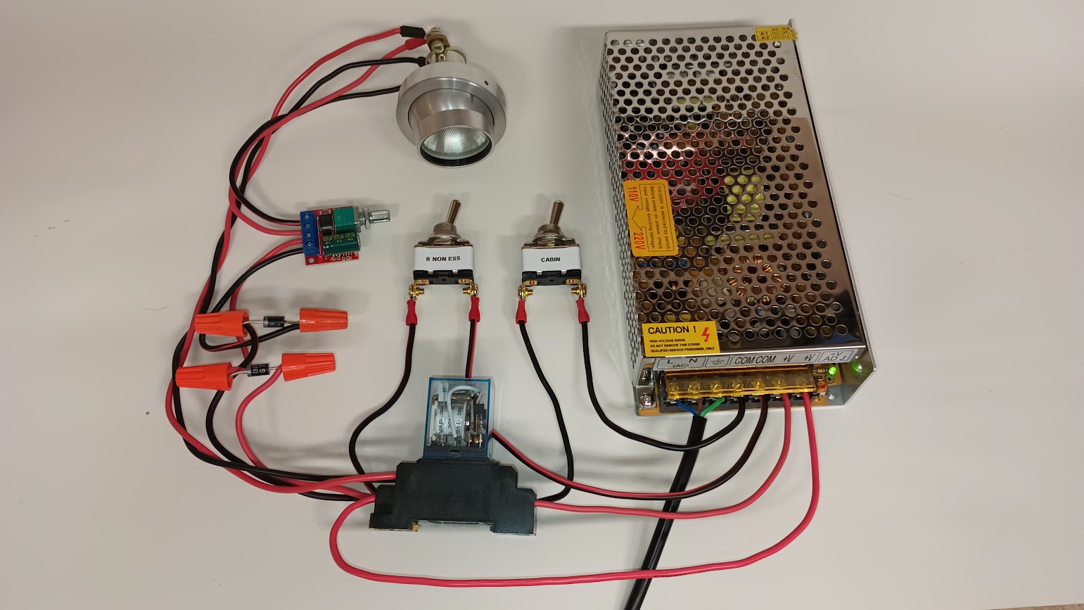
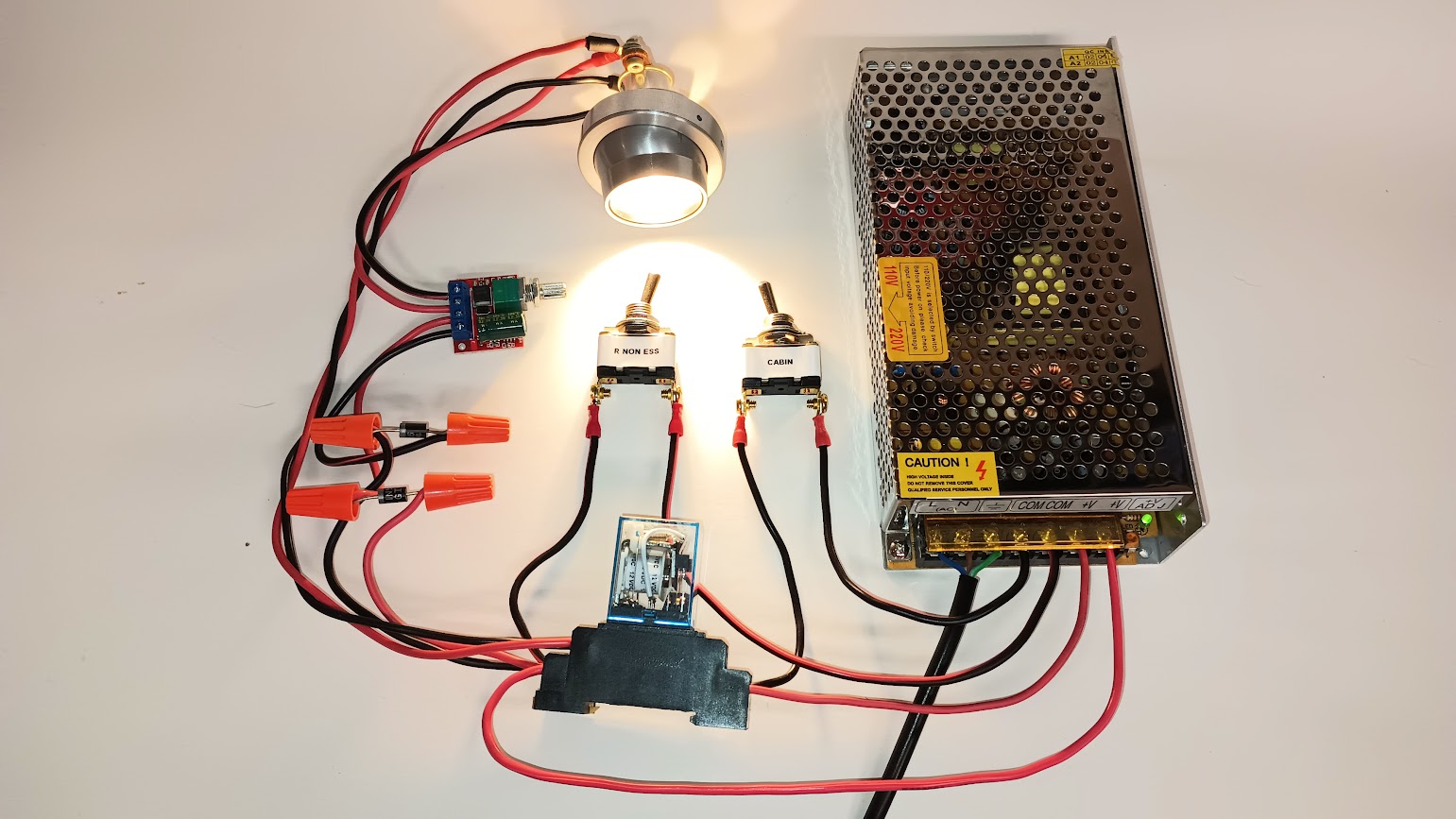
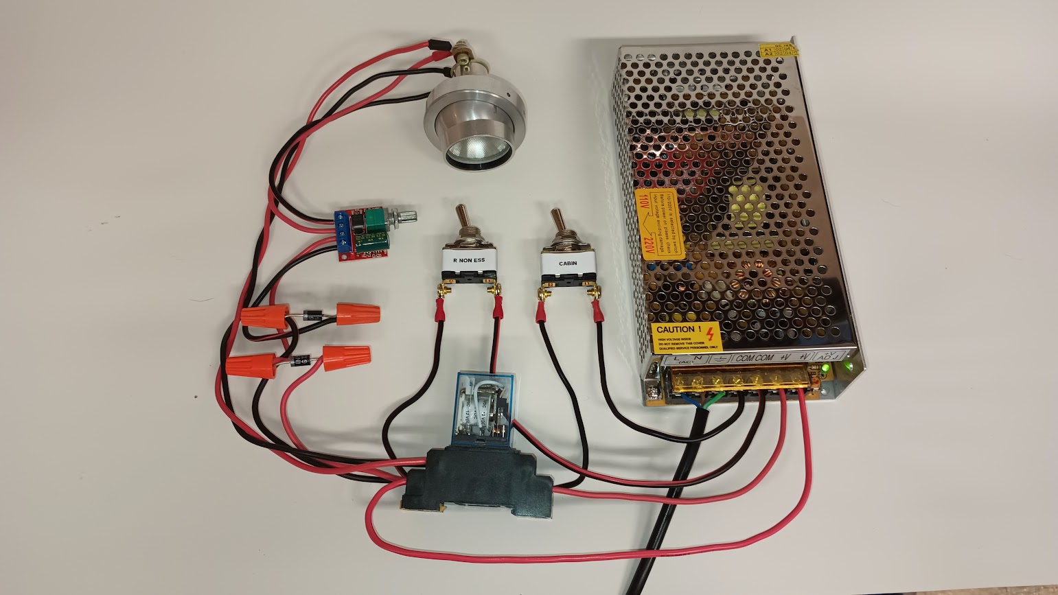
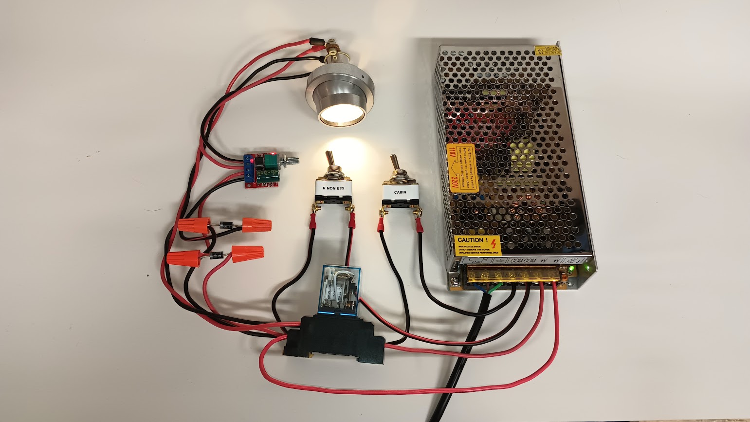
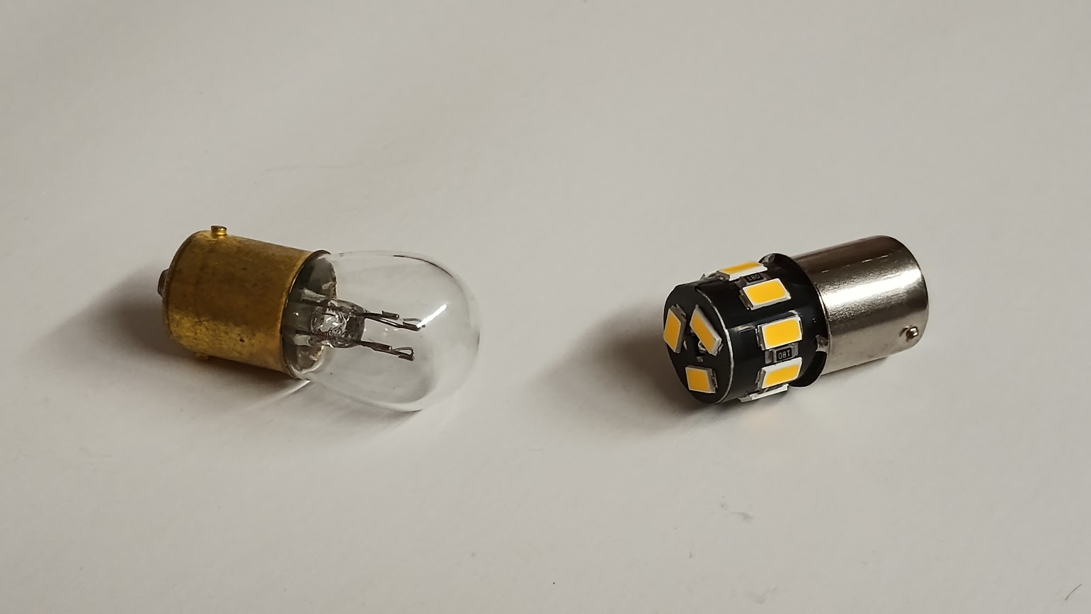
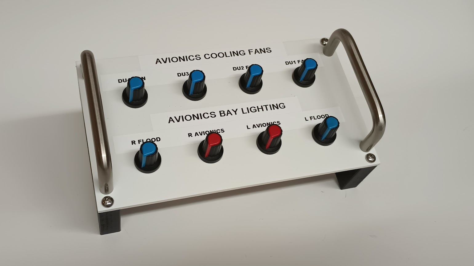
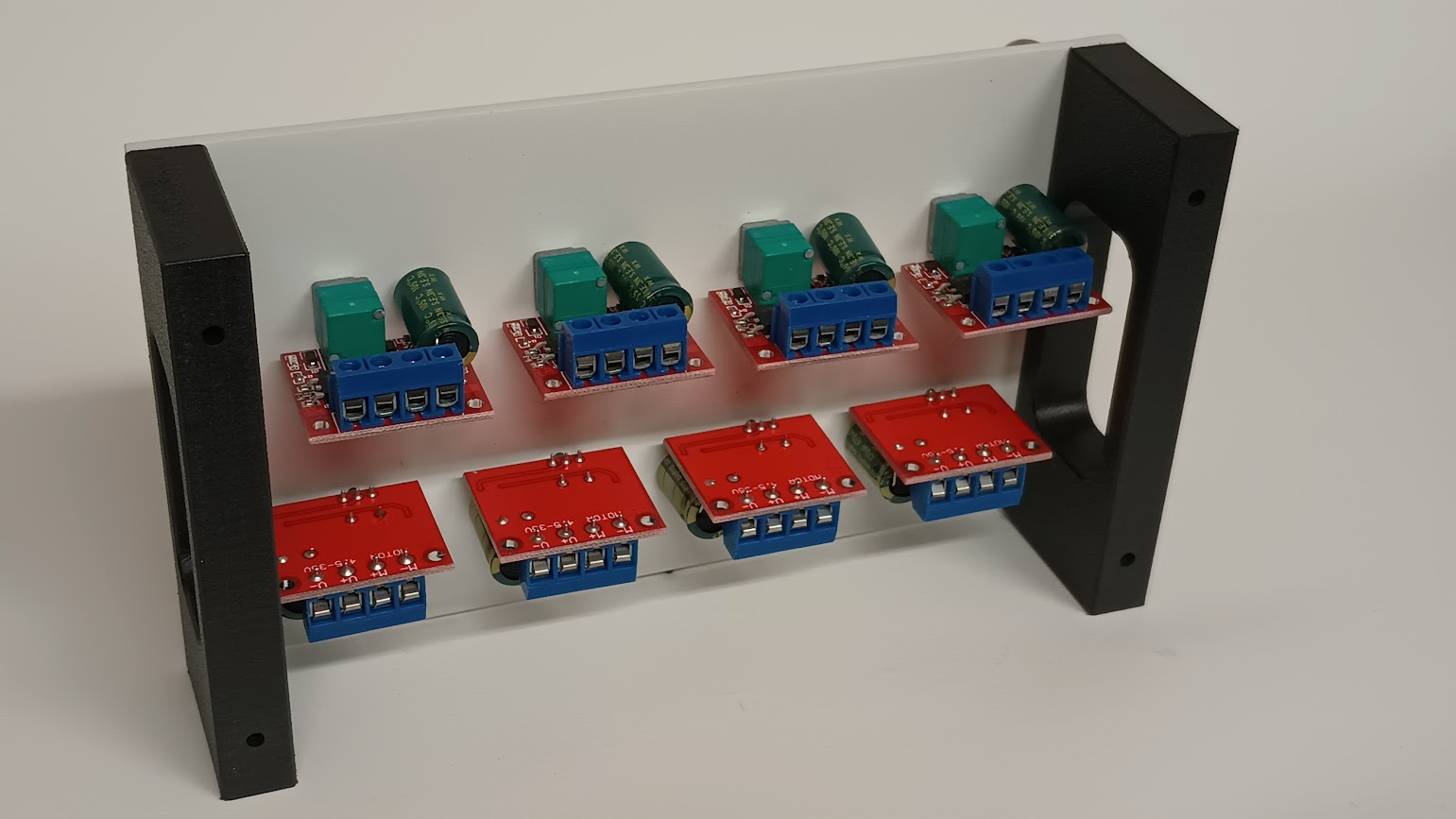
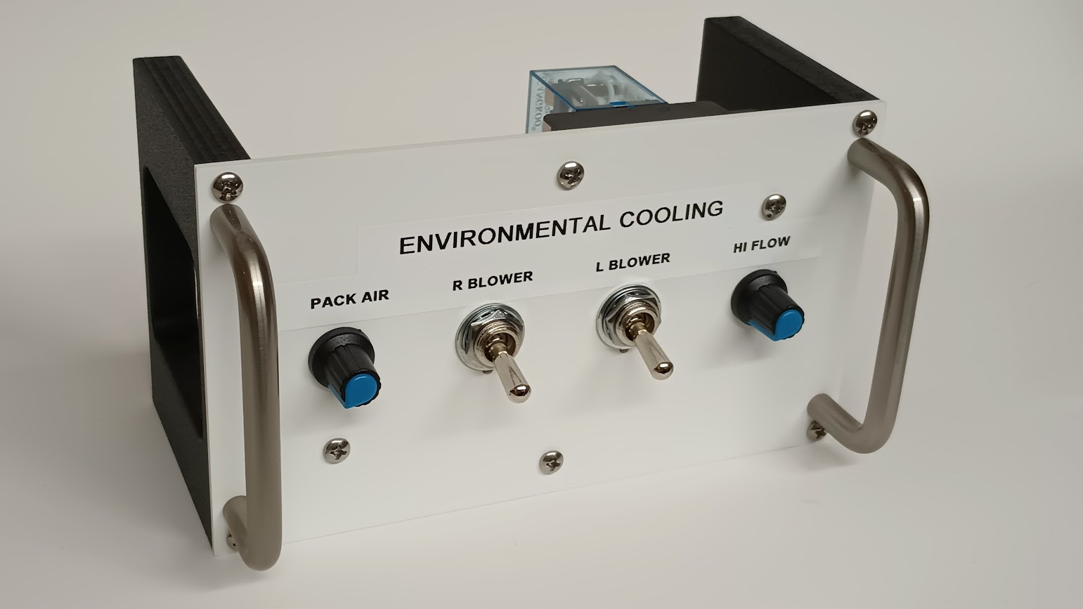
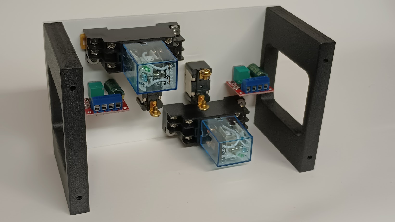
![]()
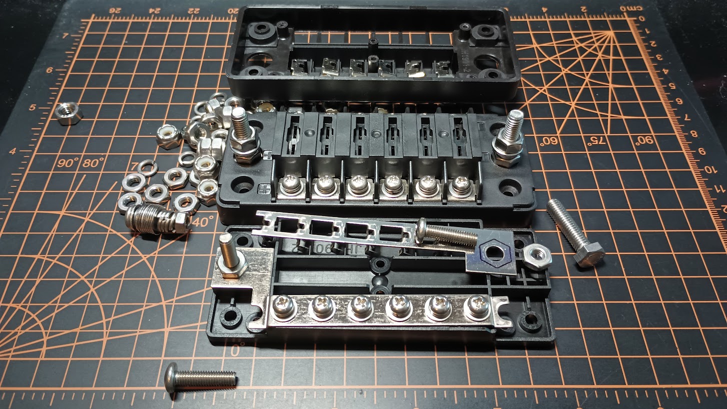
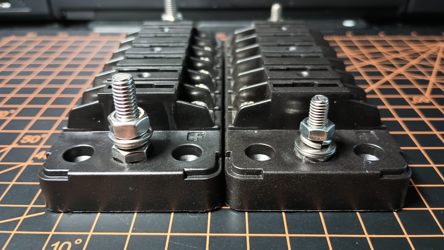
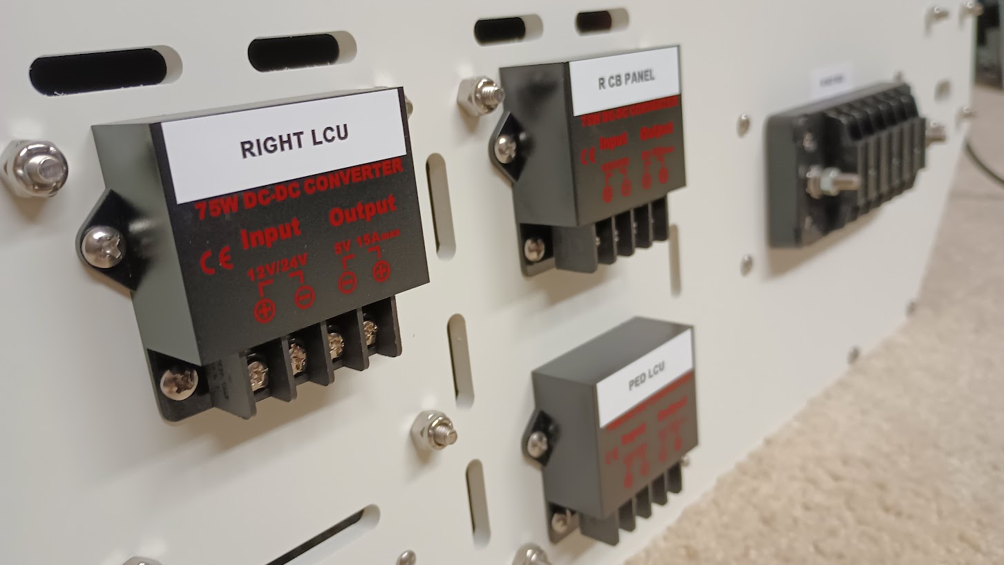
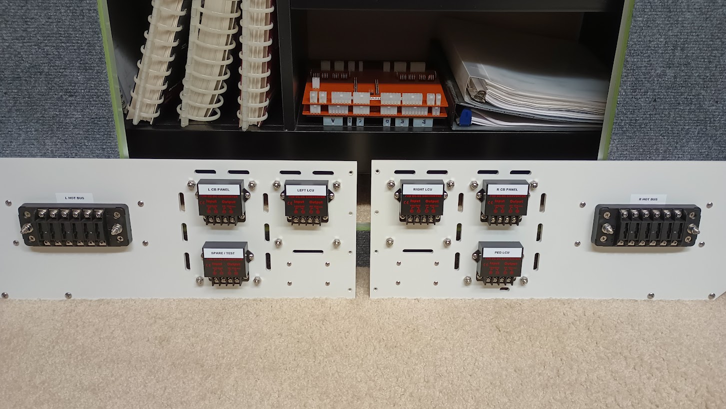
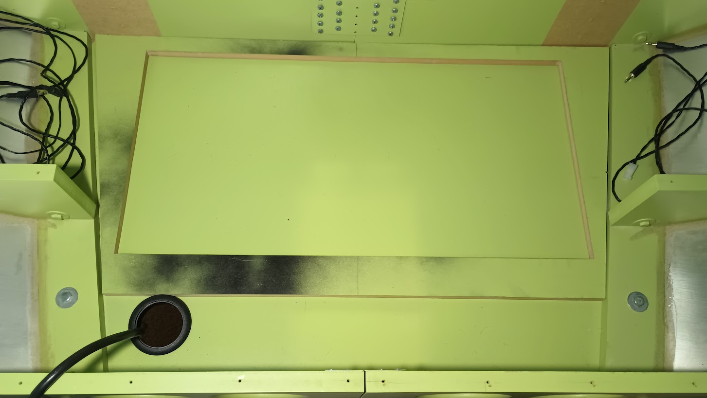
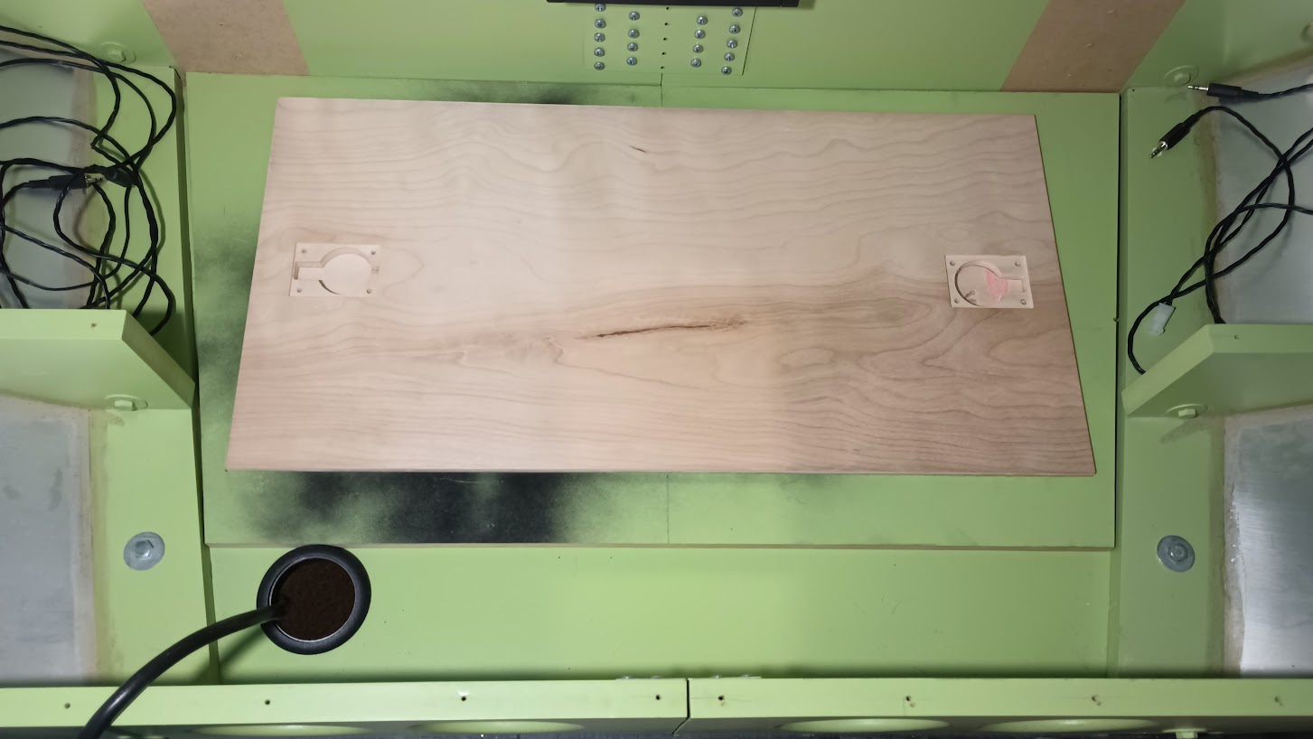
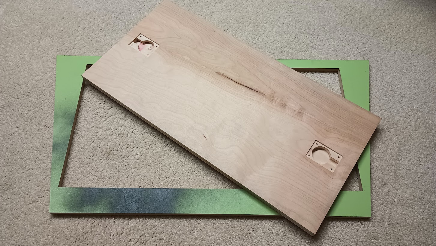
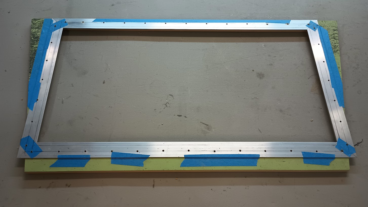
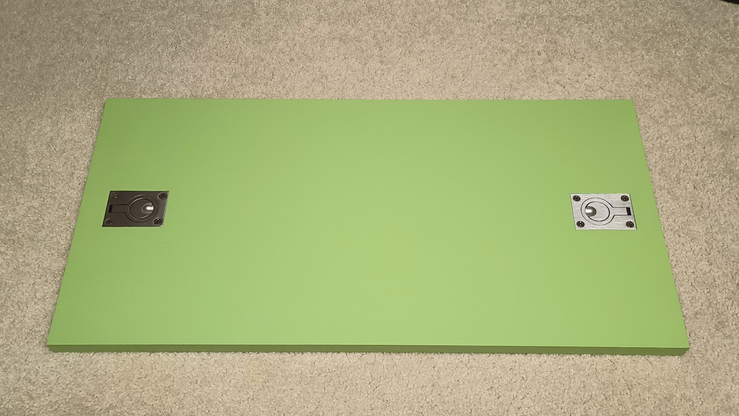
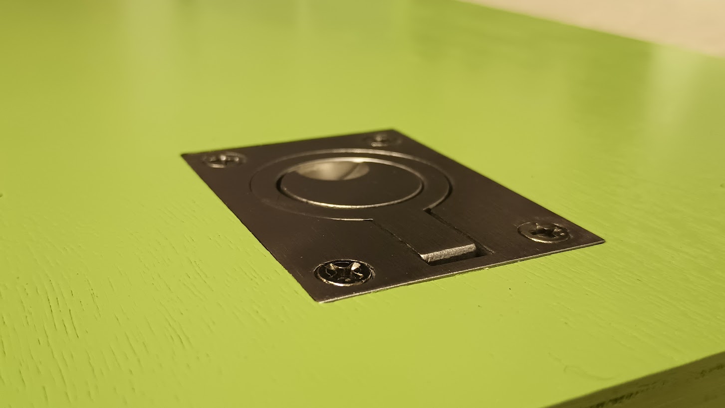
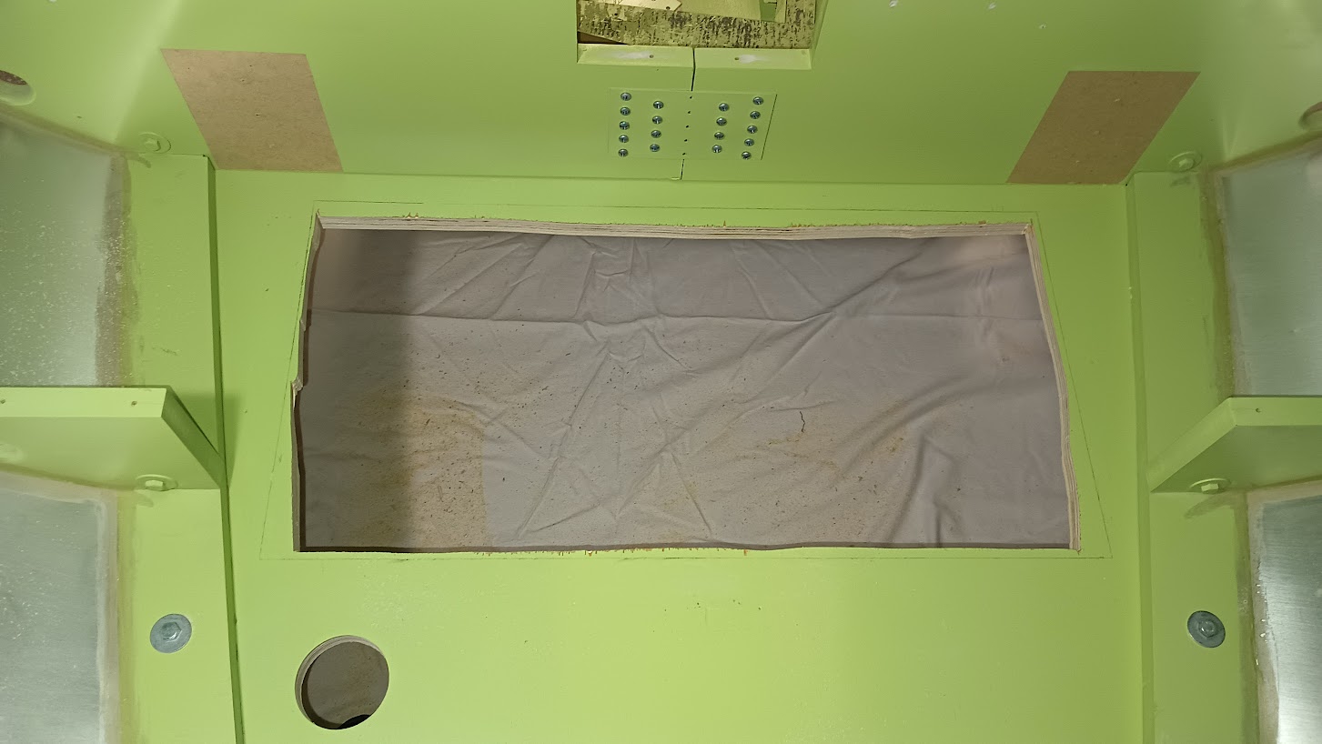
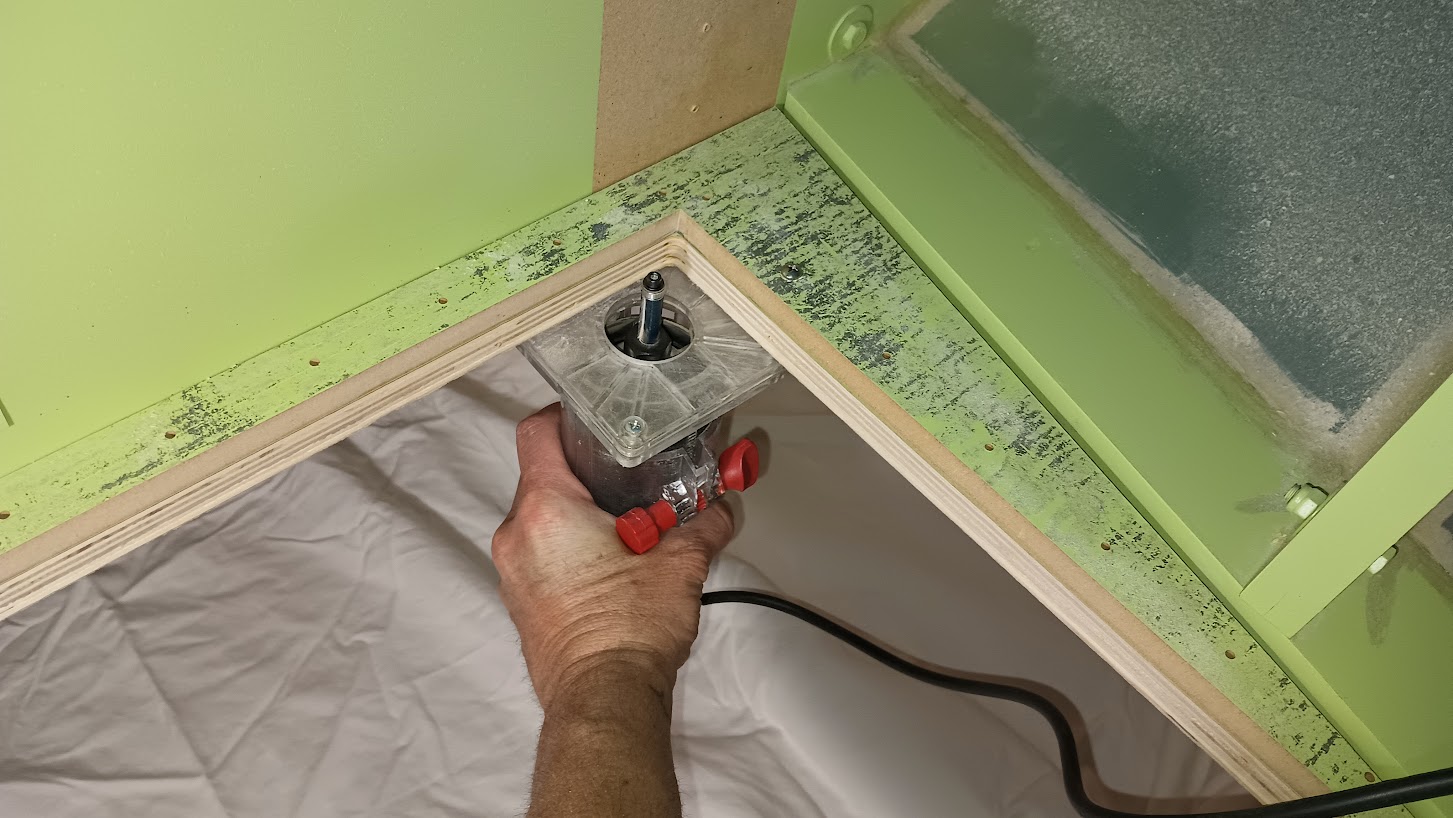
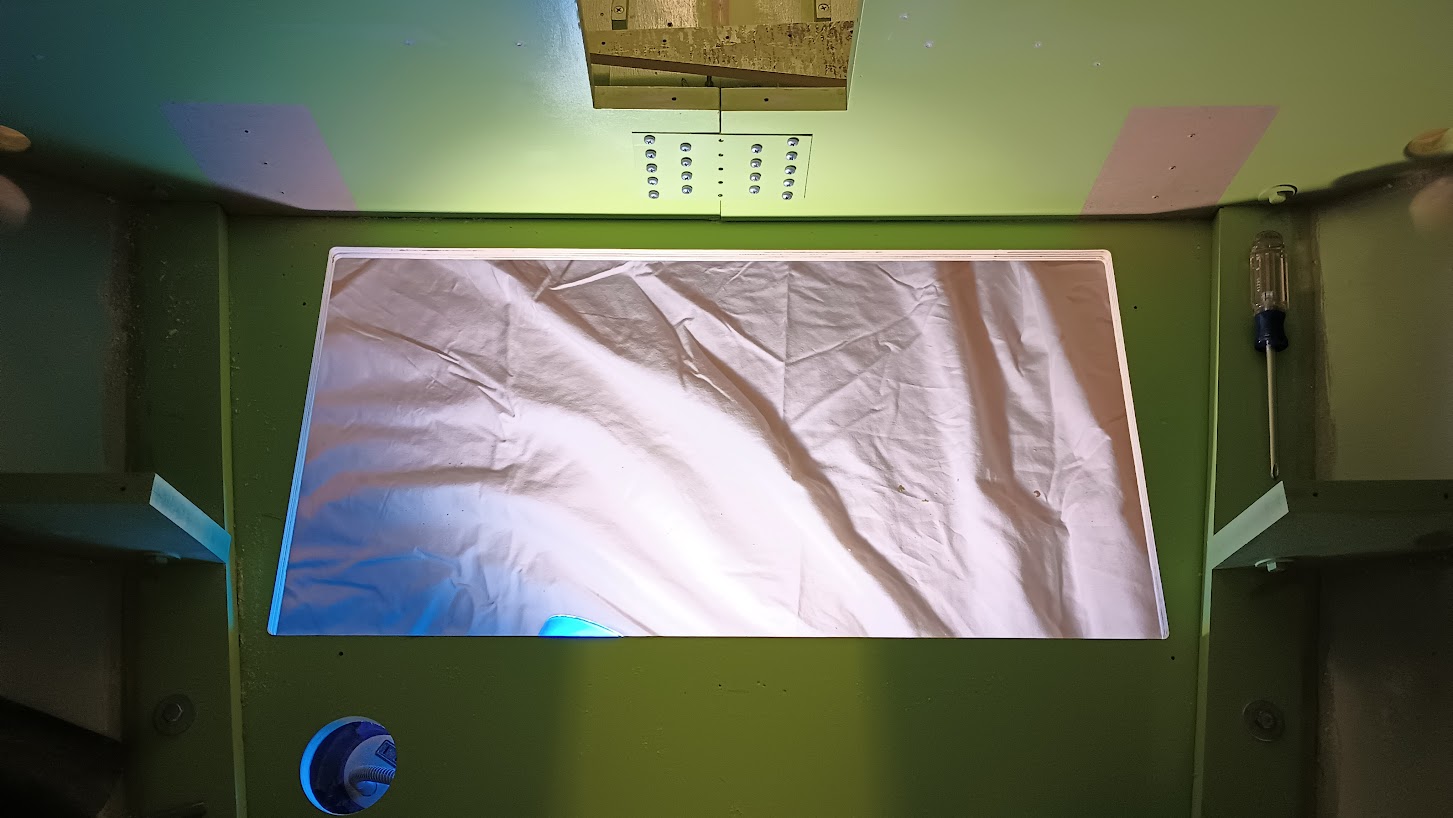
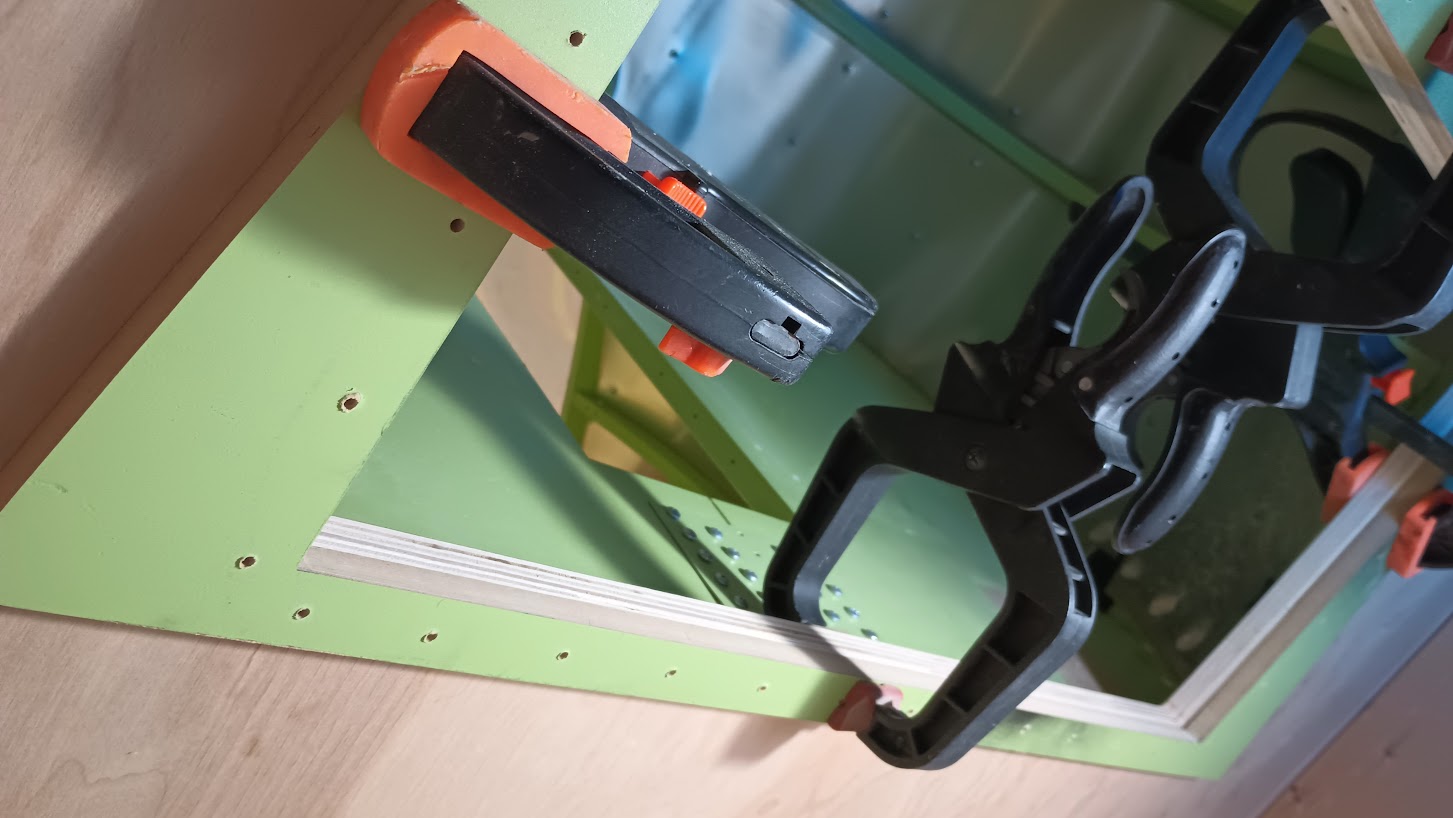
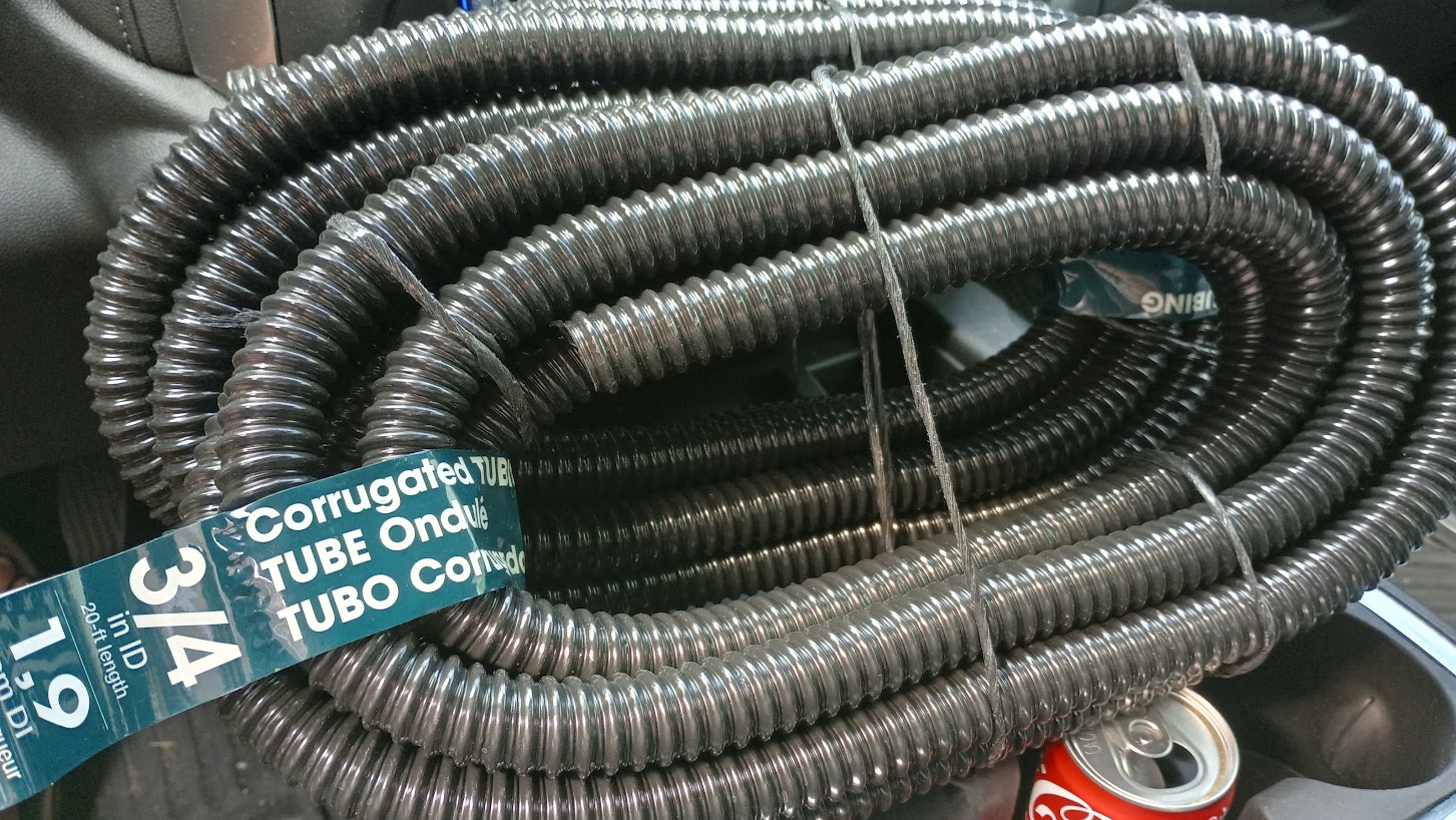
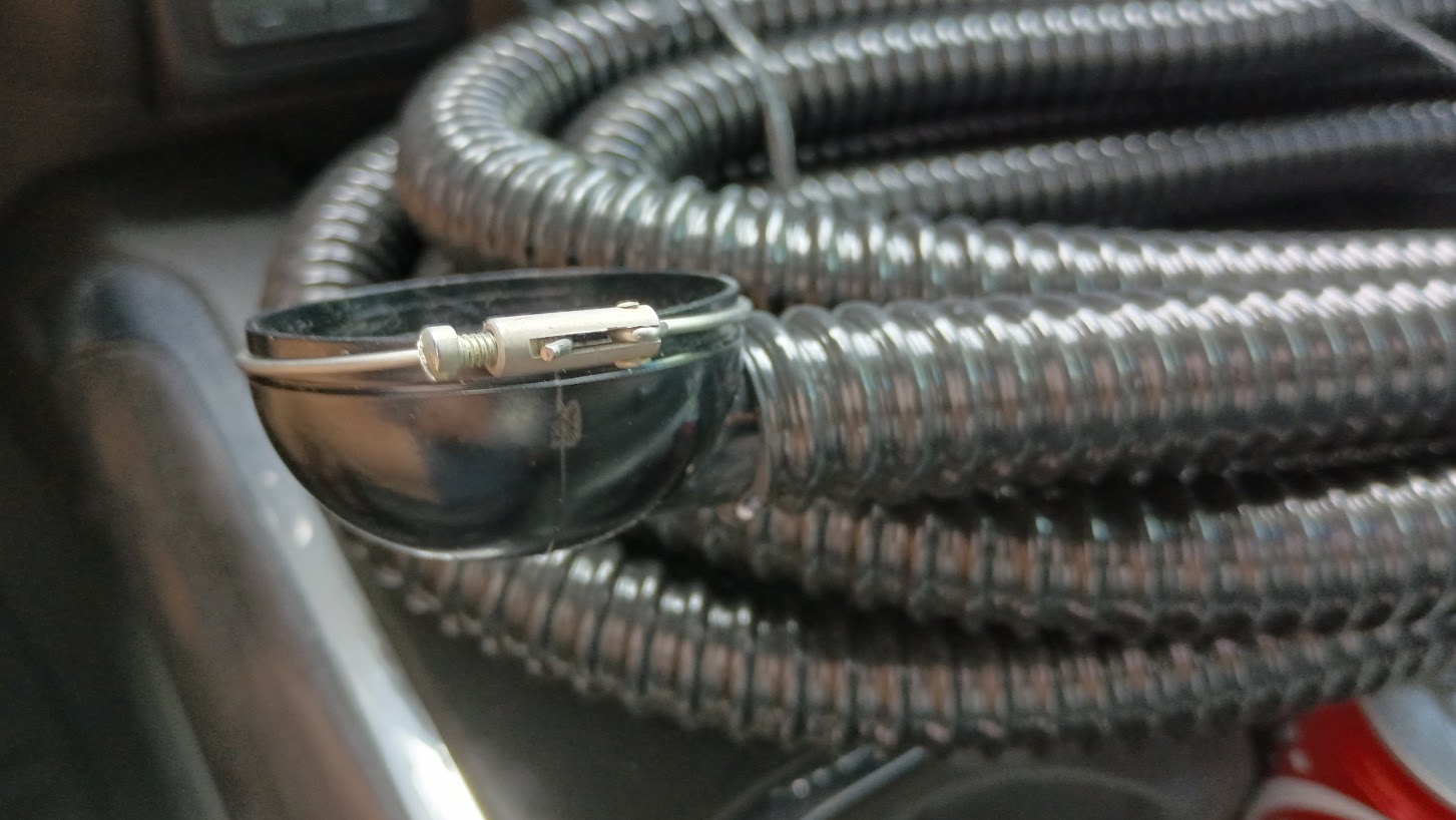
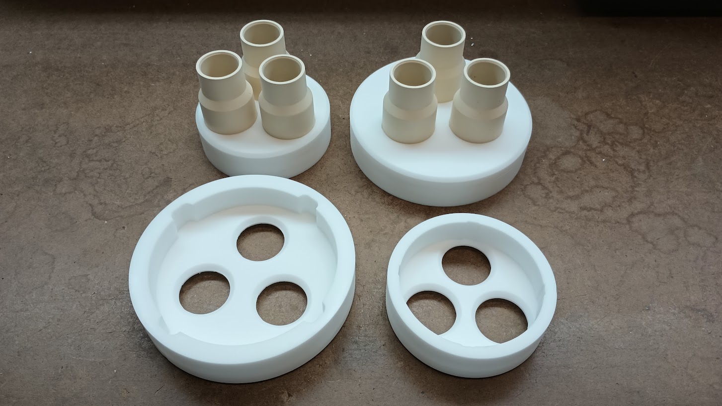
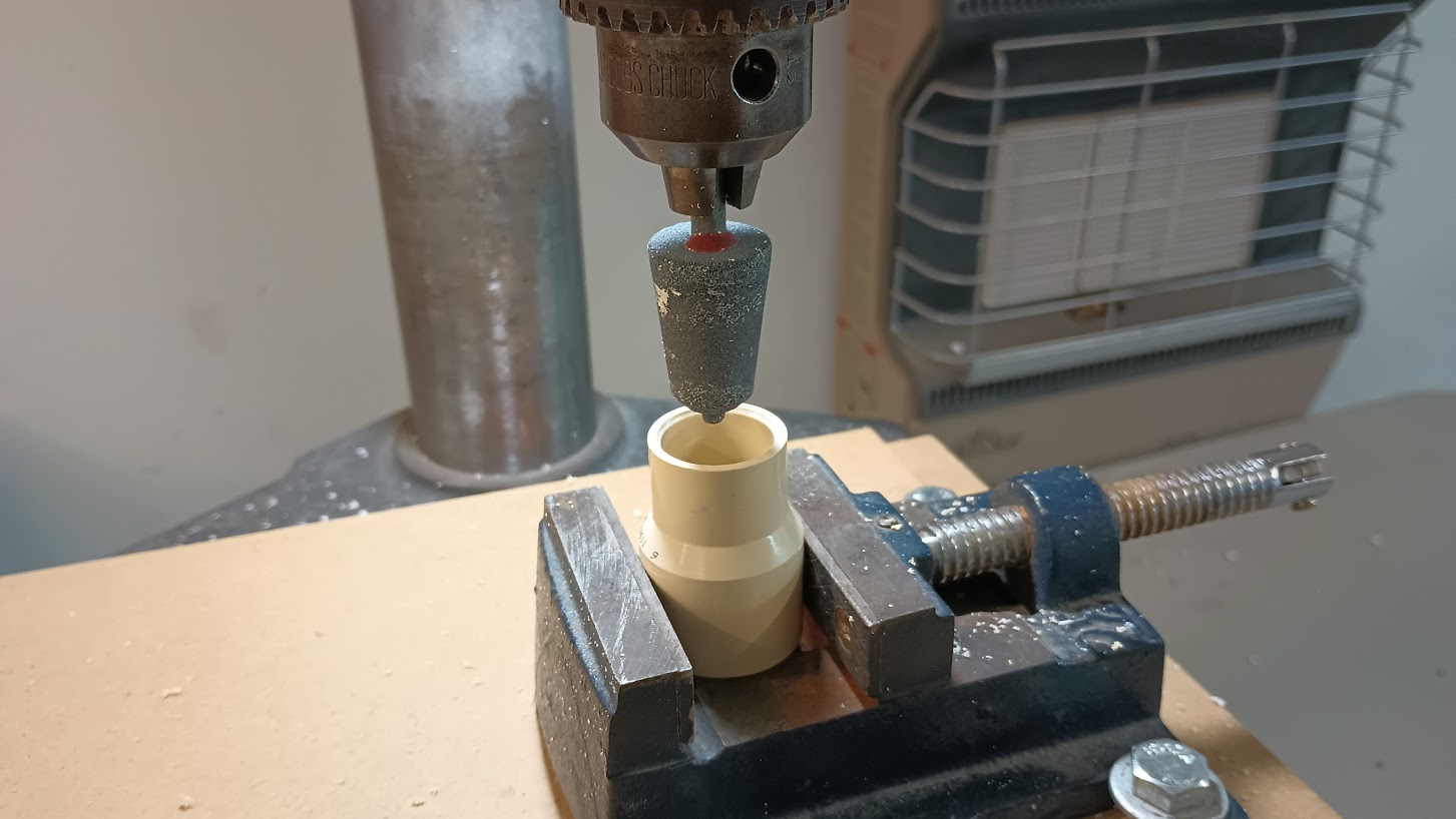
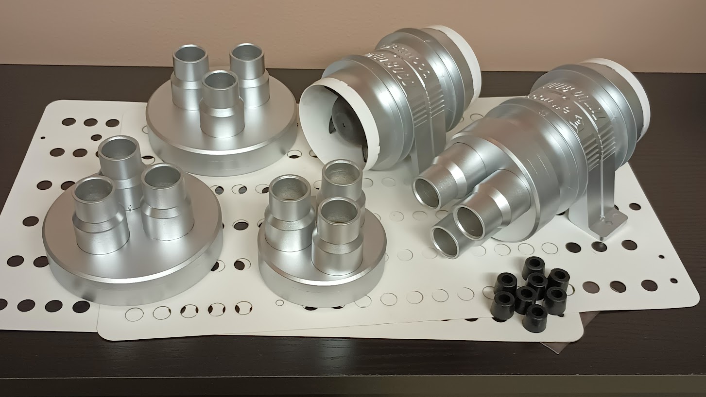
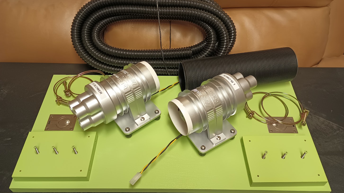
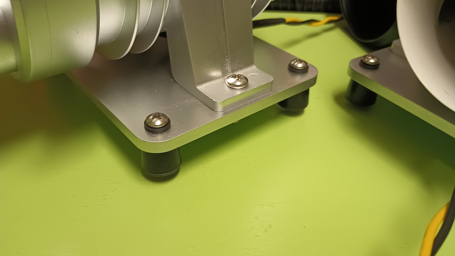
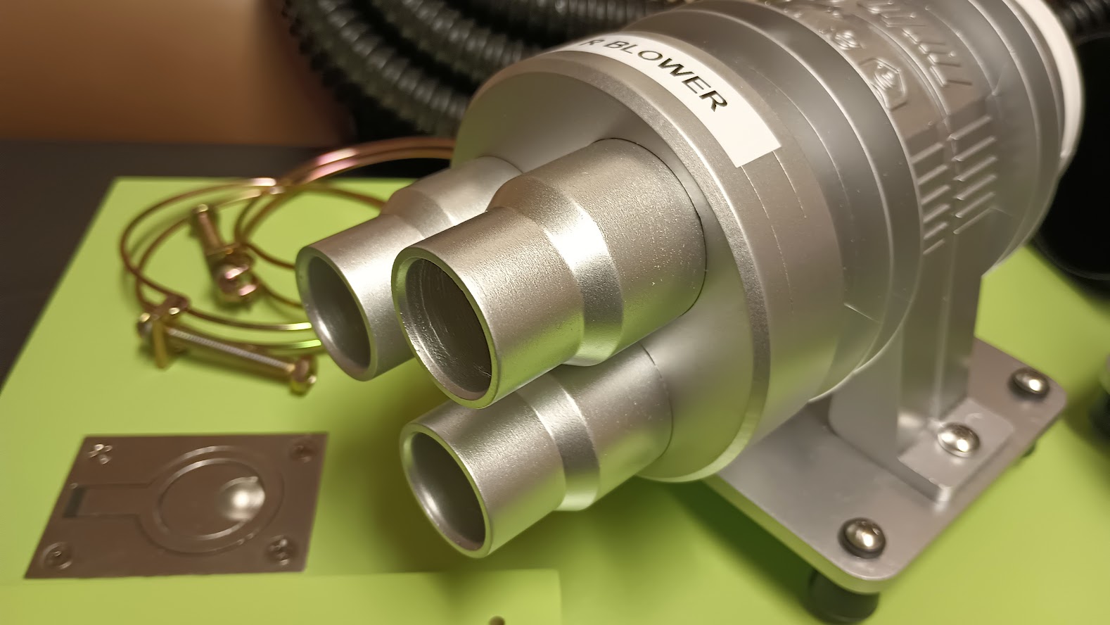
![]()
![]()
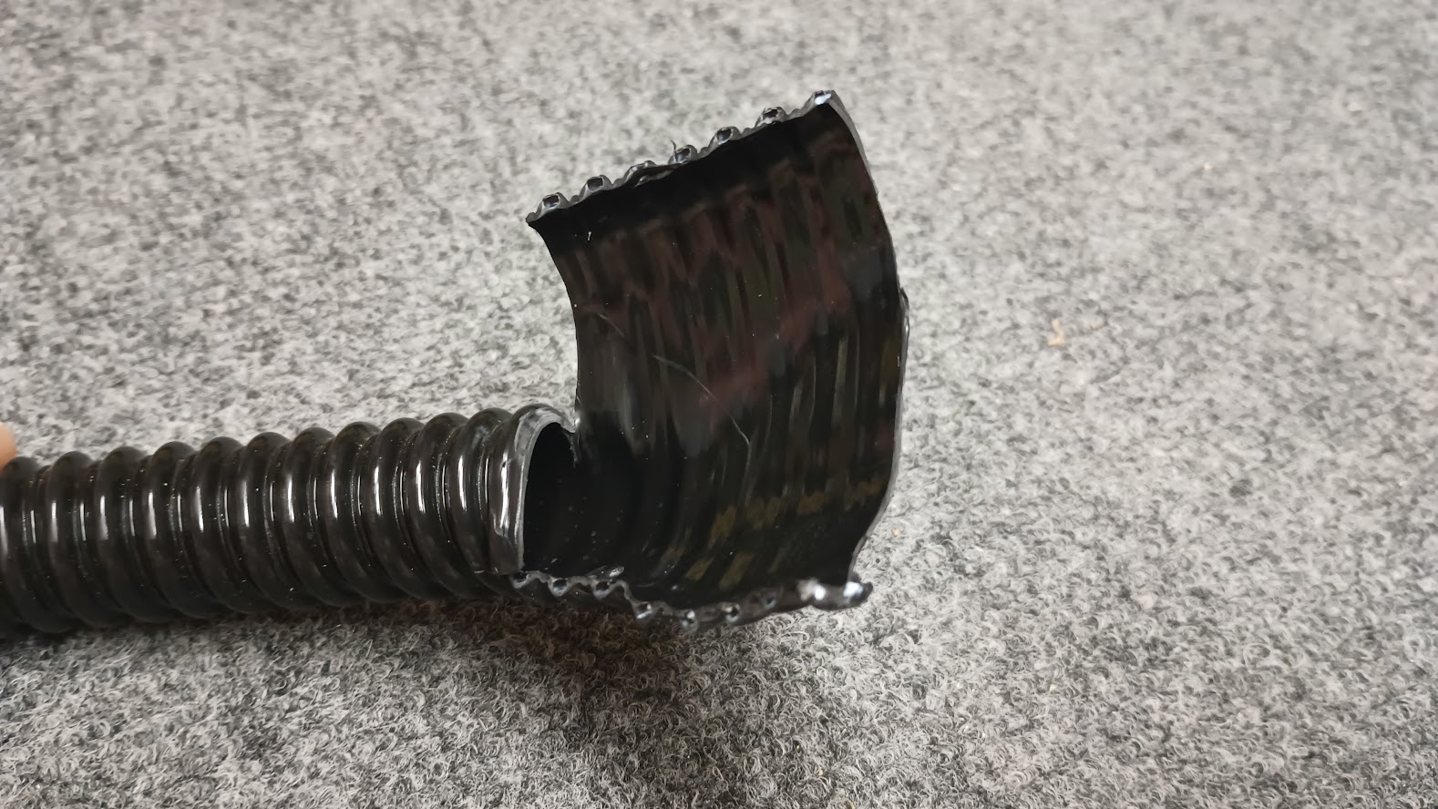
![]()


![]()


![]()
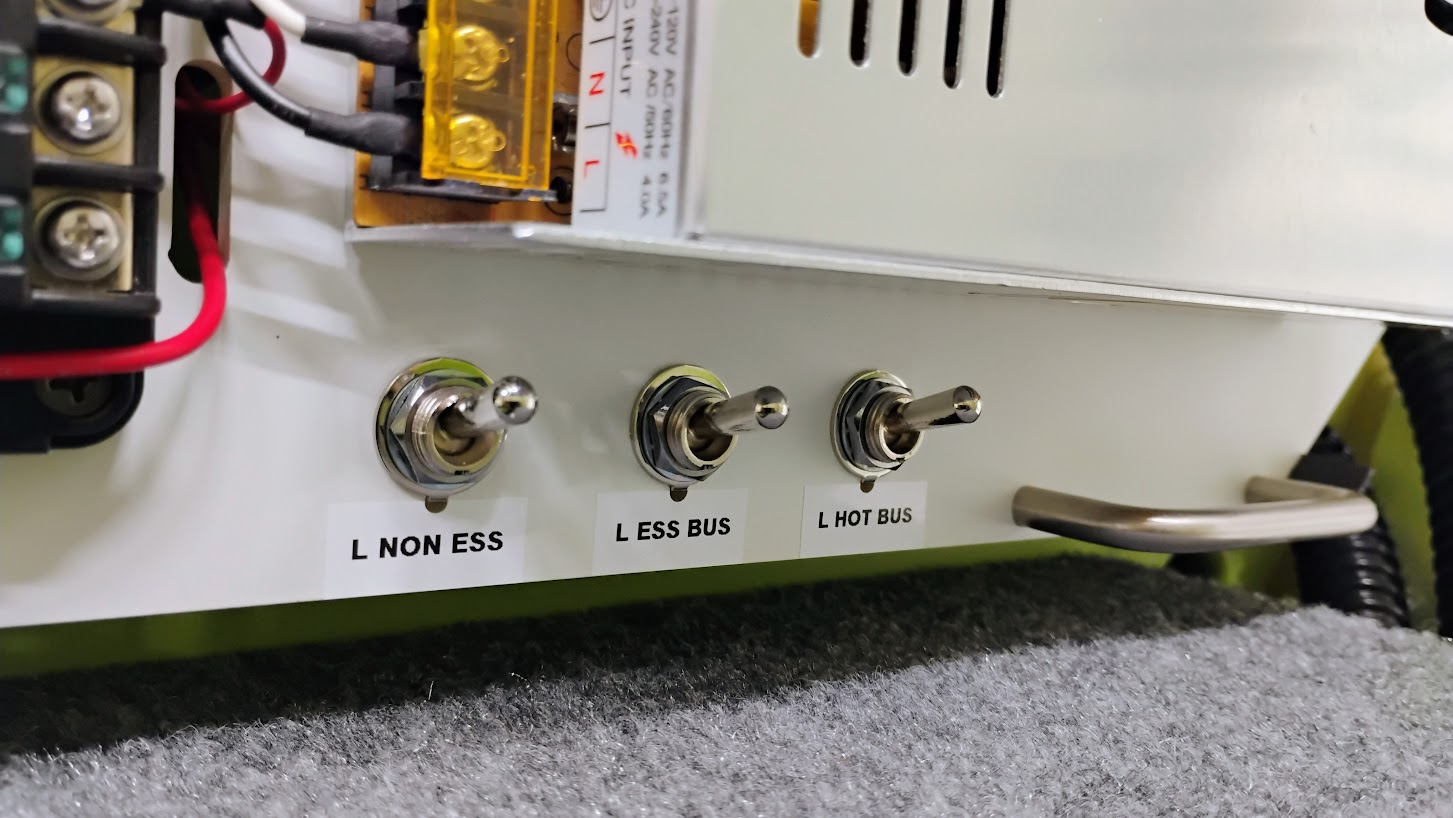
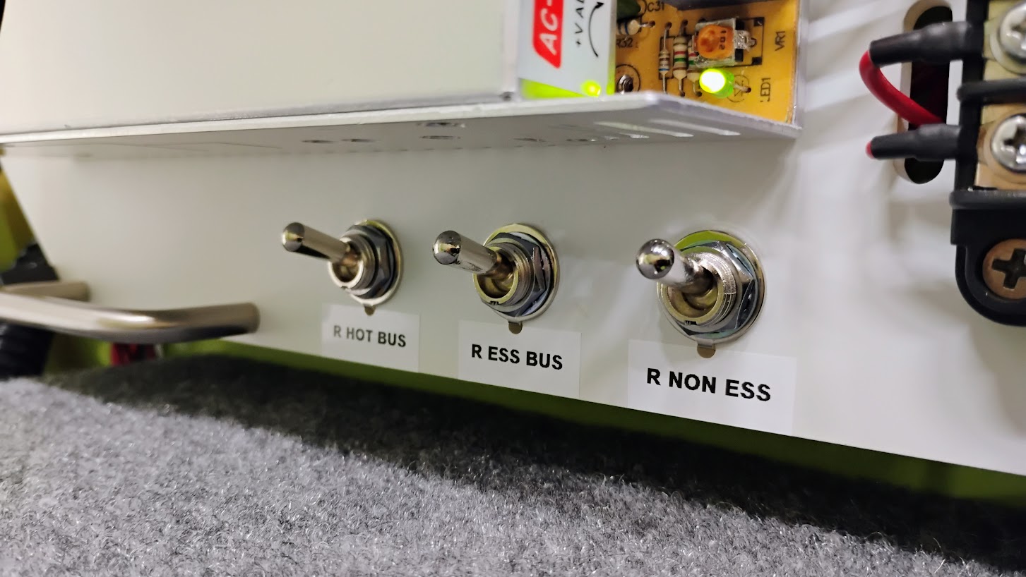
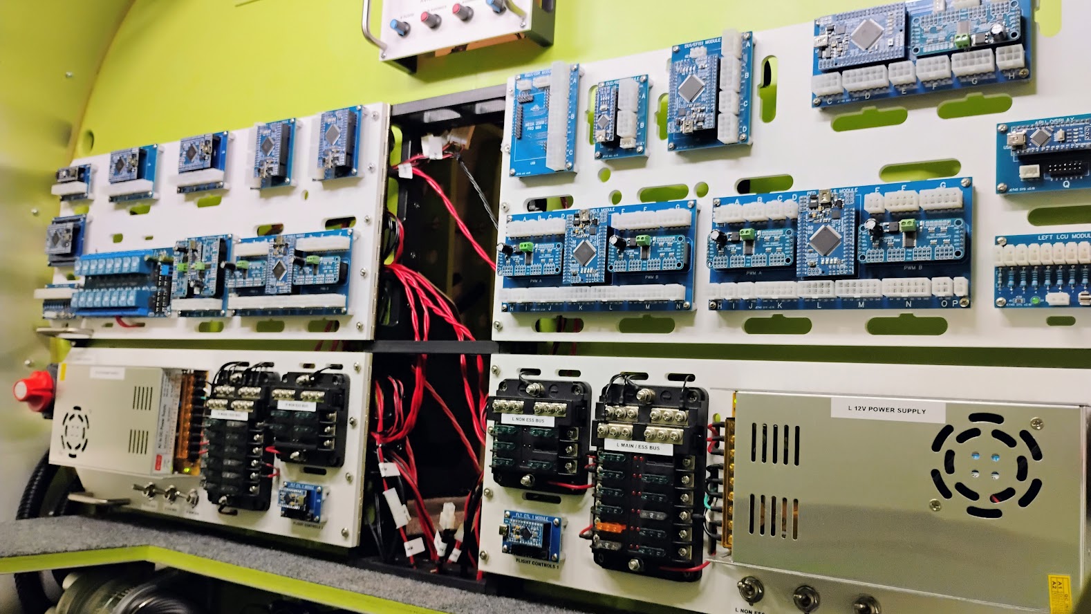
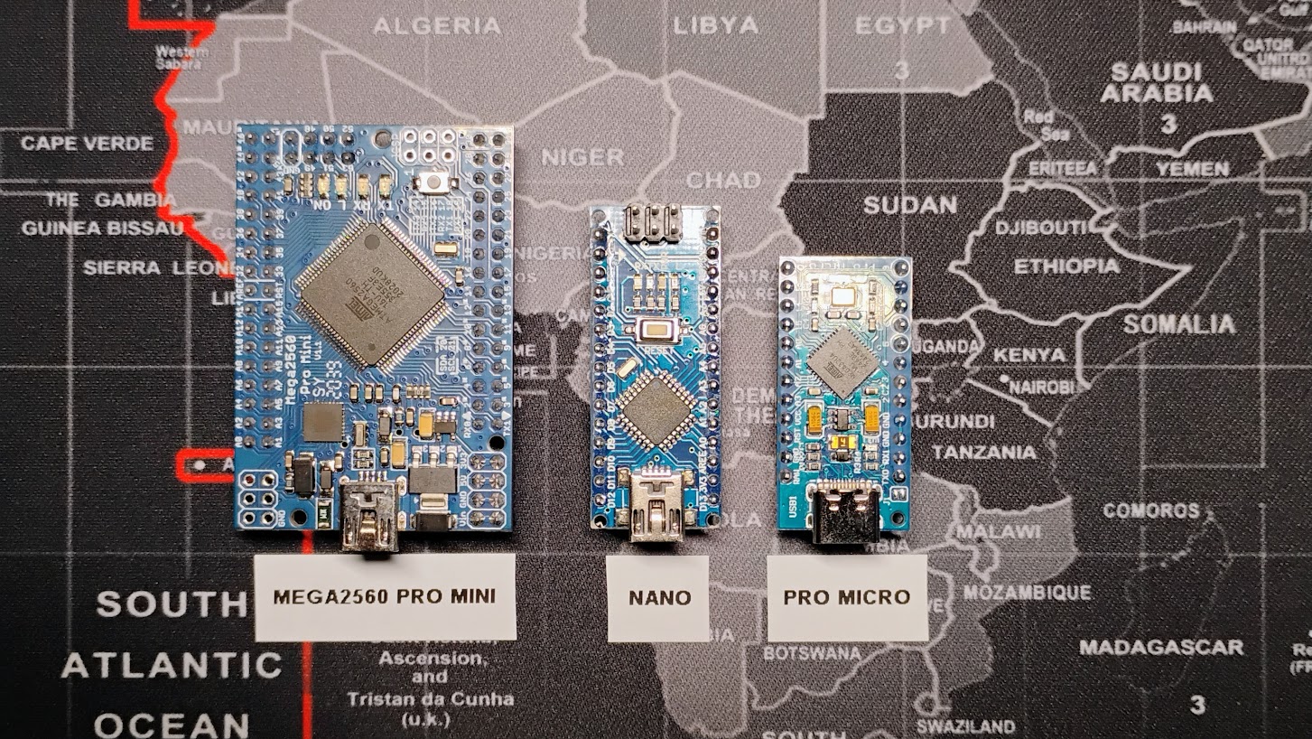
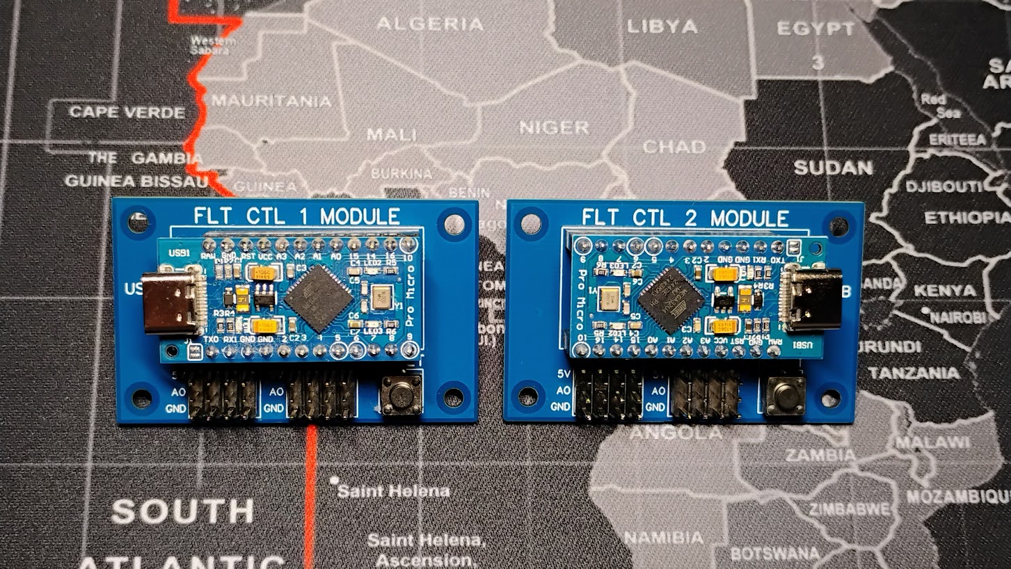
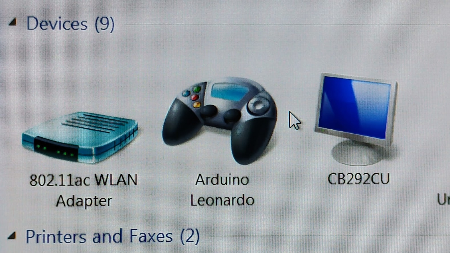
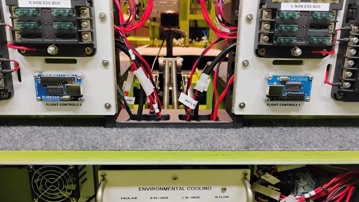
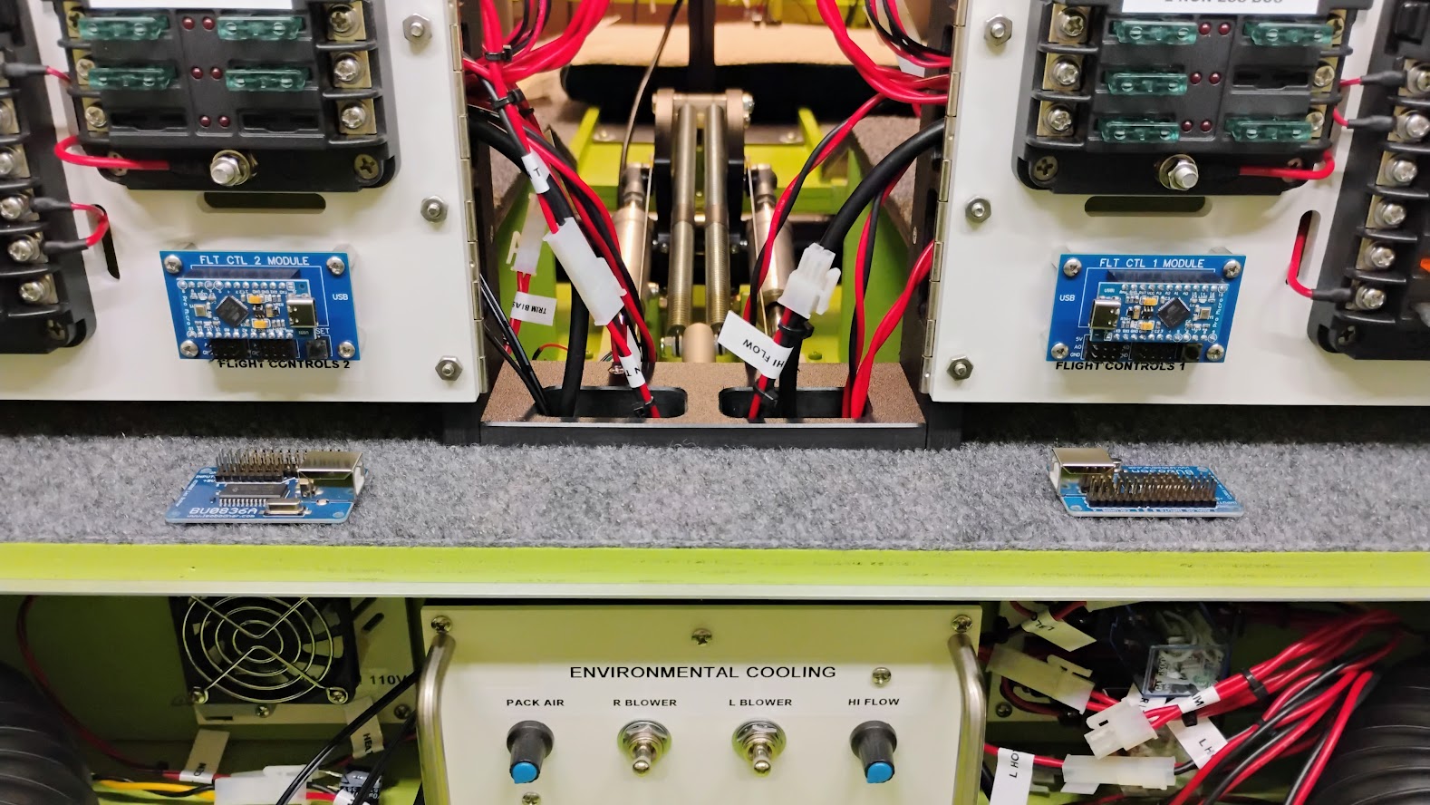
![]()
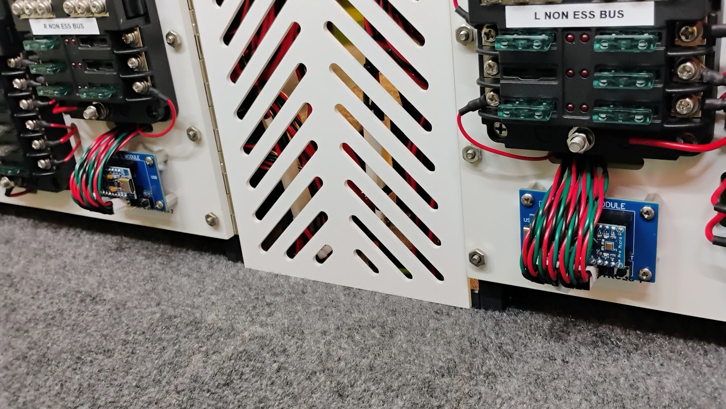
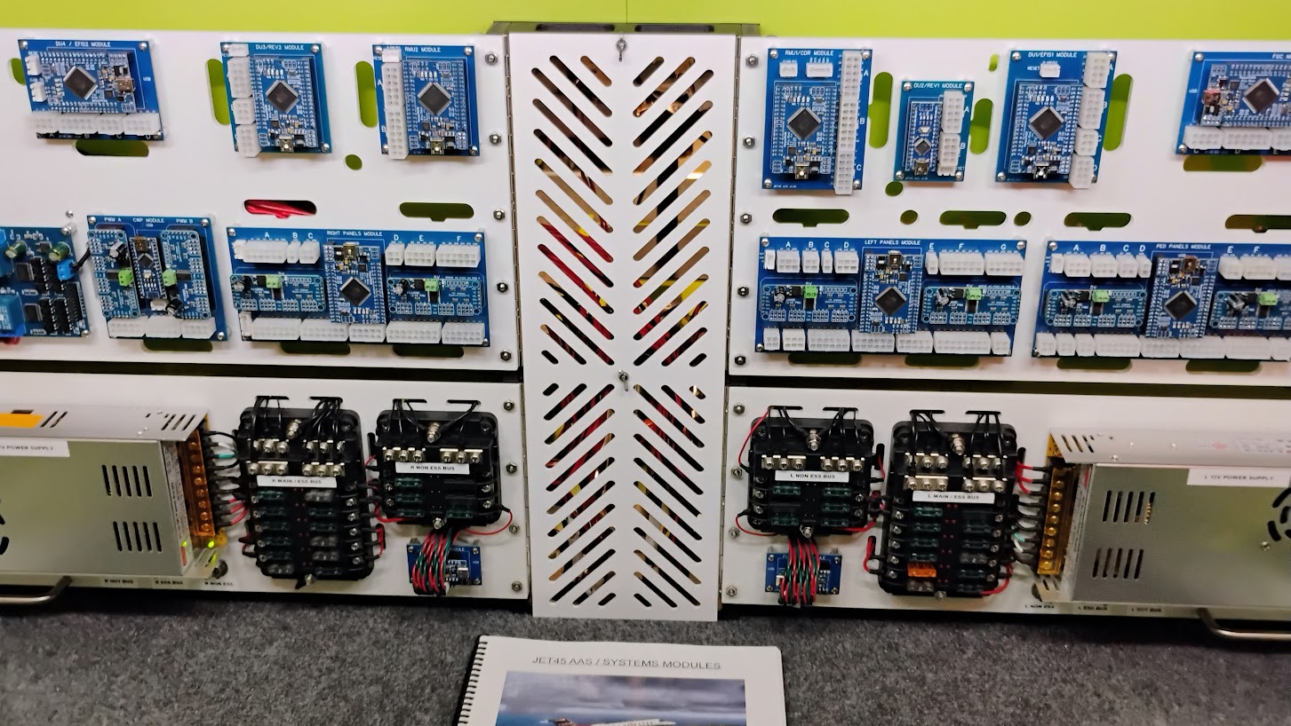
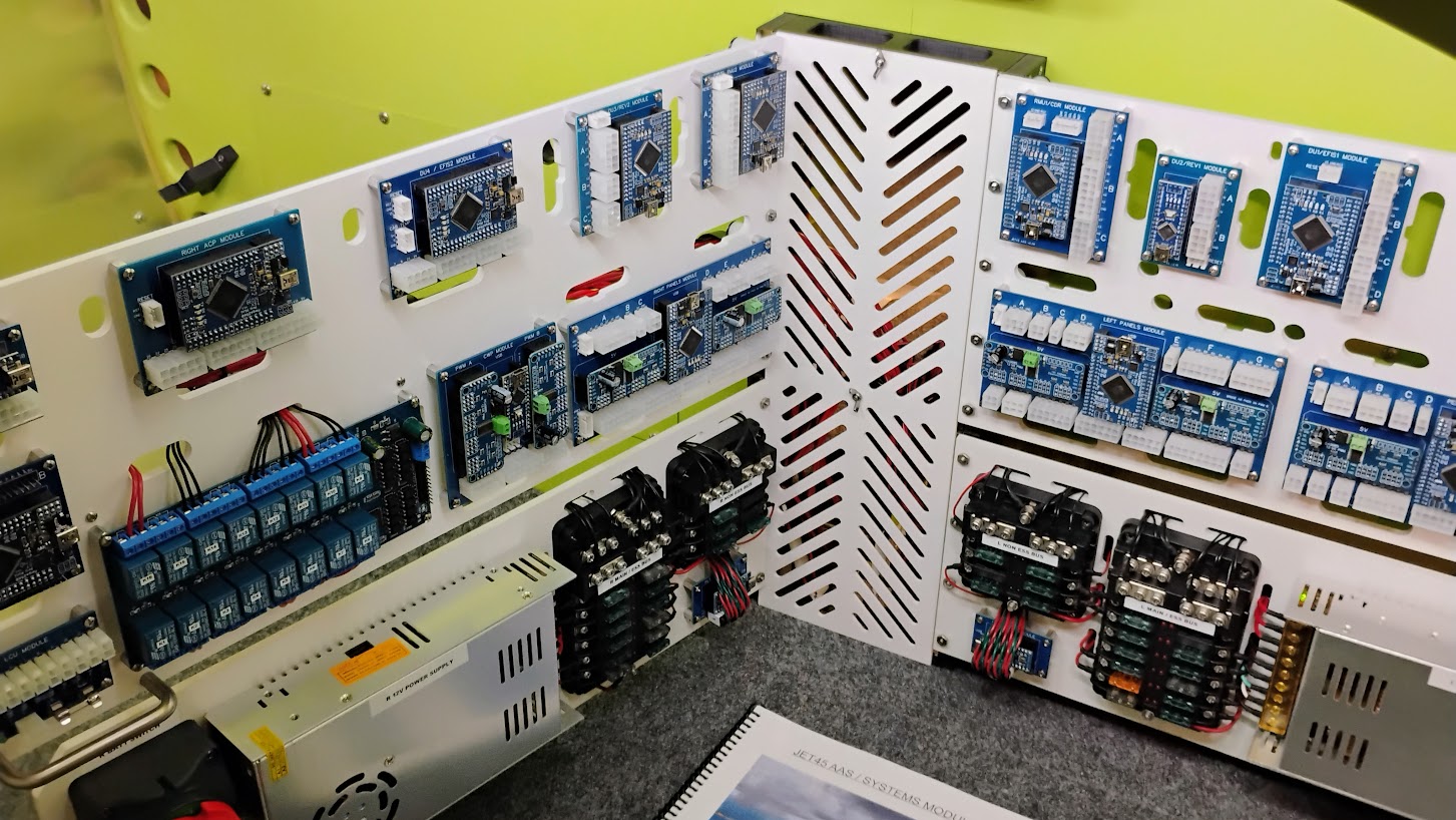
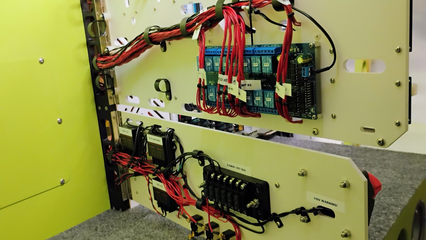
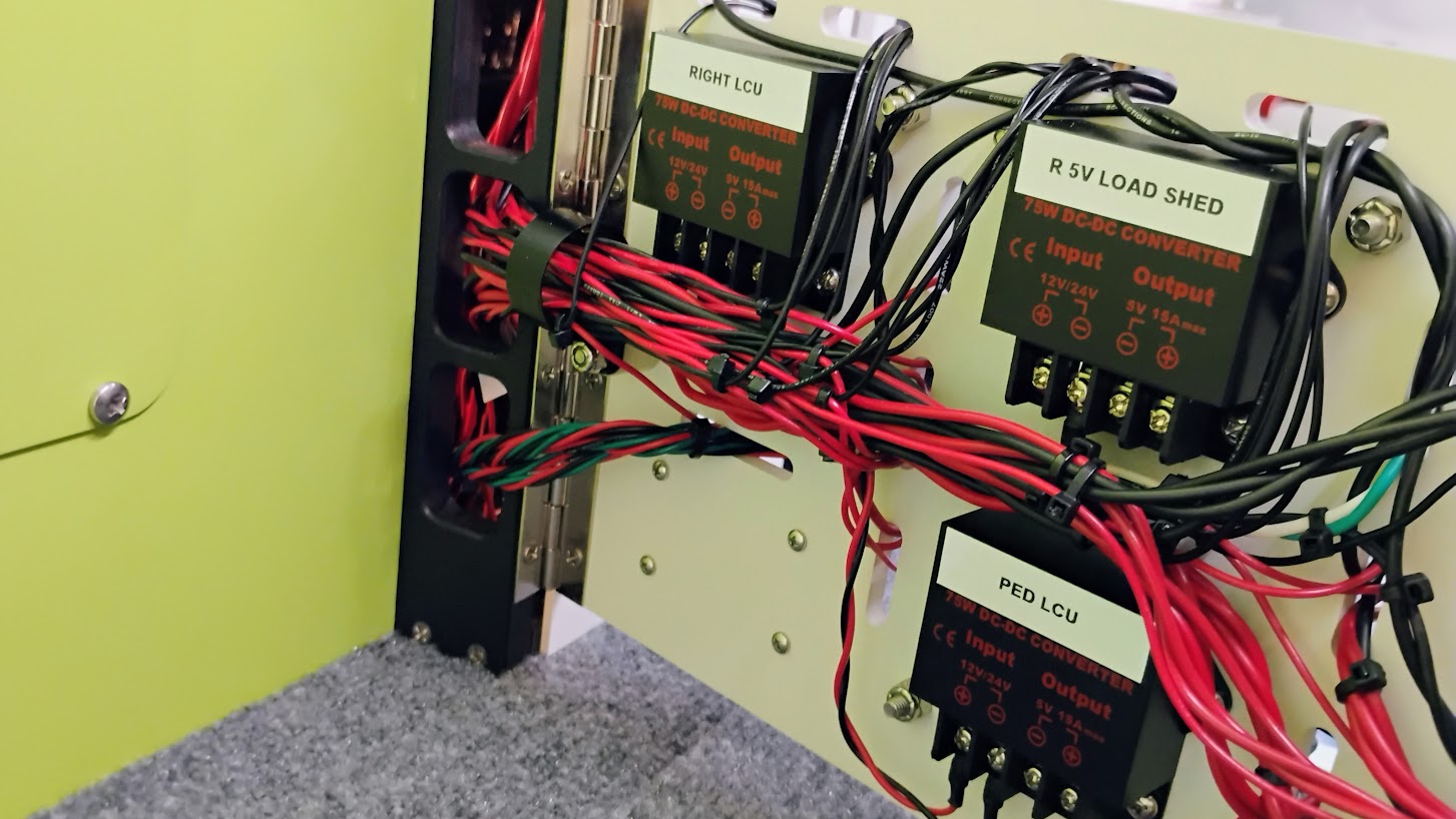
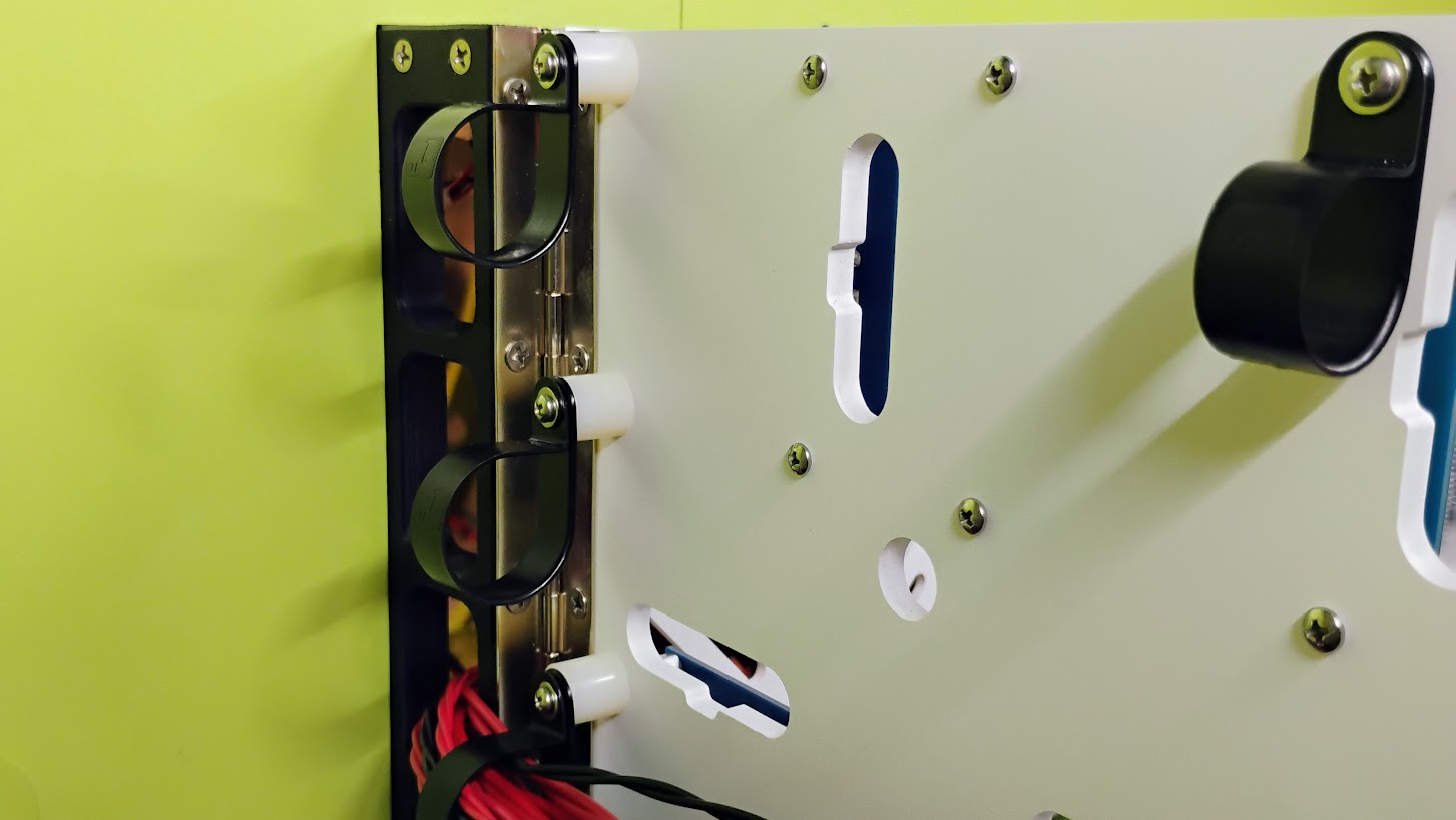
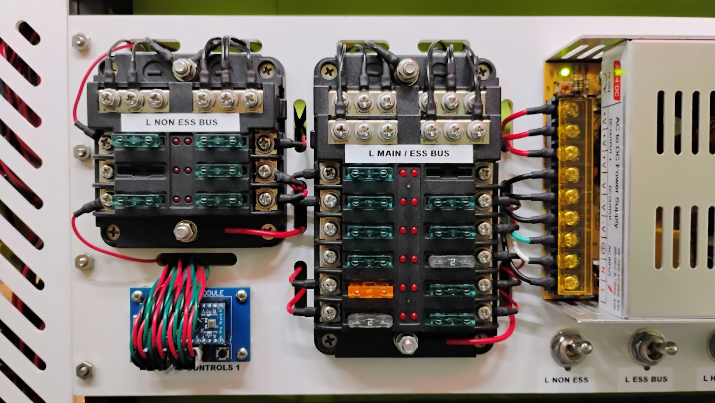
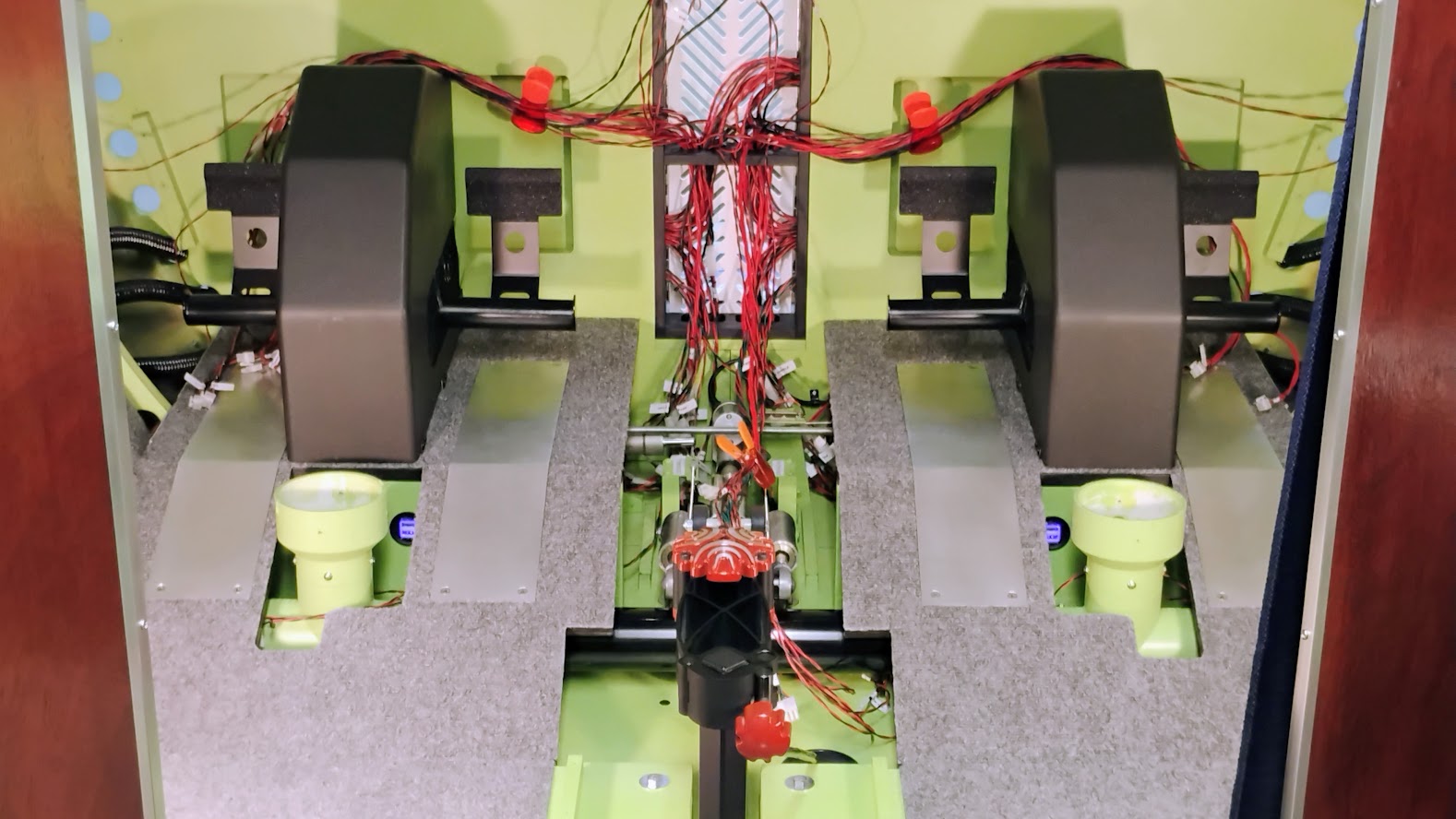
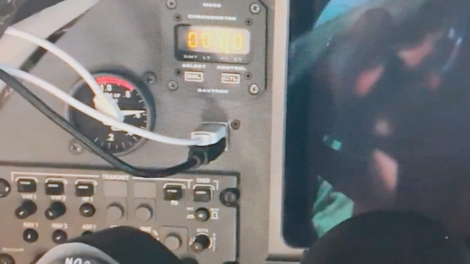
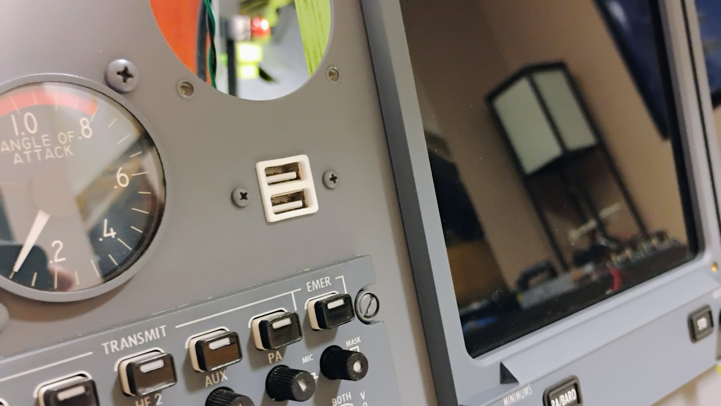
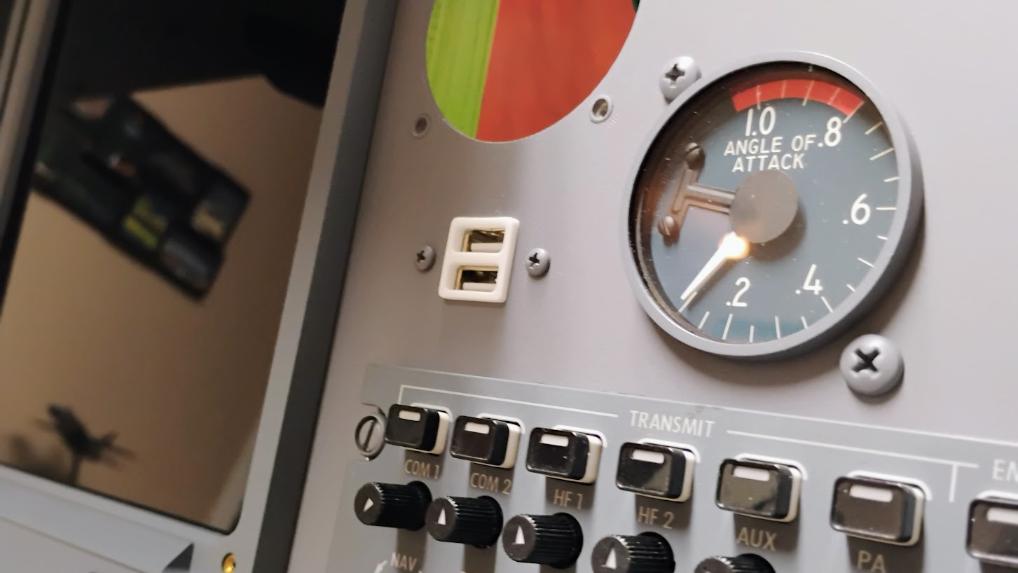
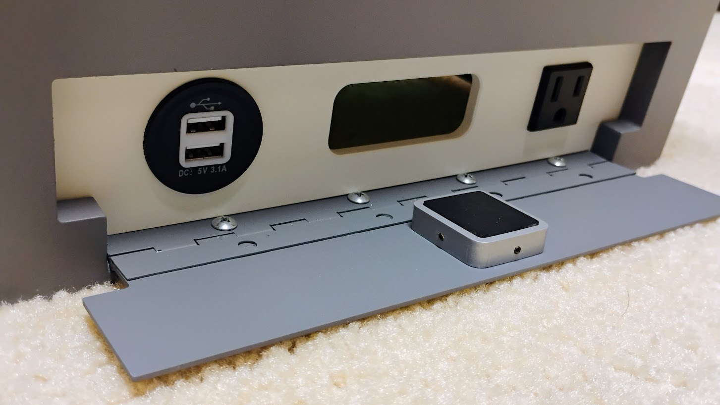
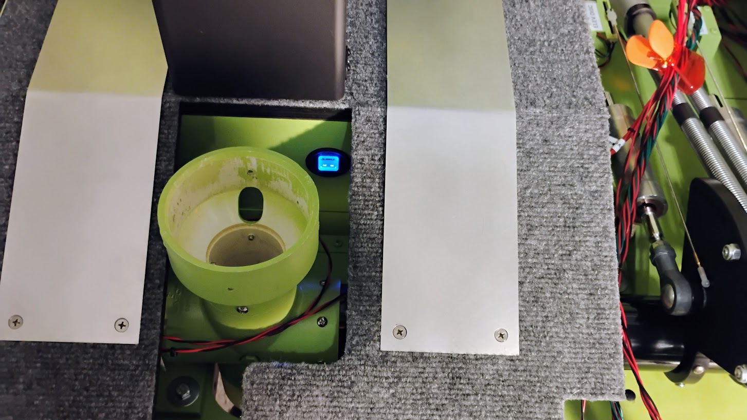
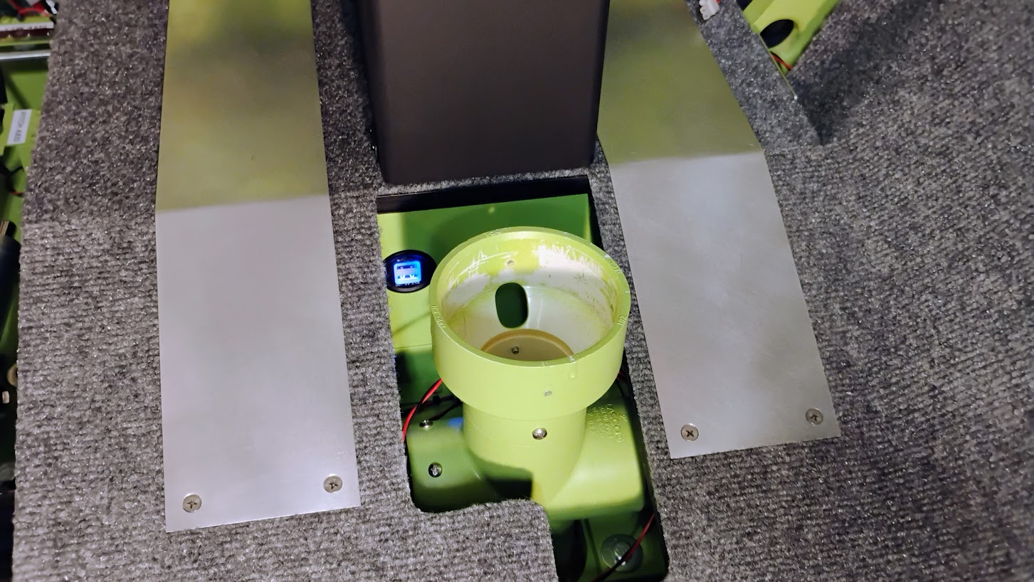
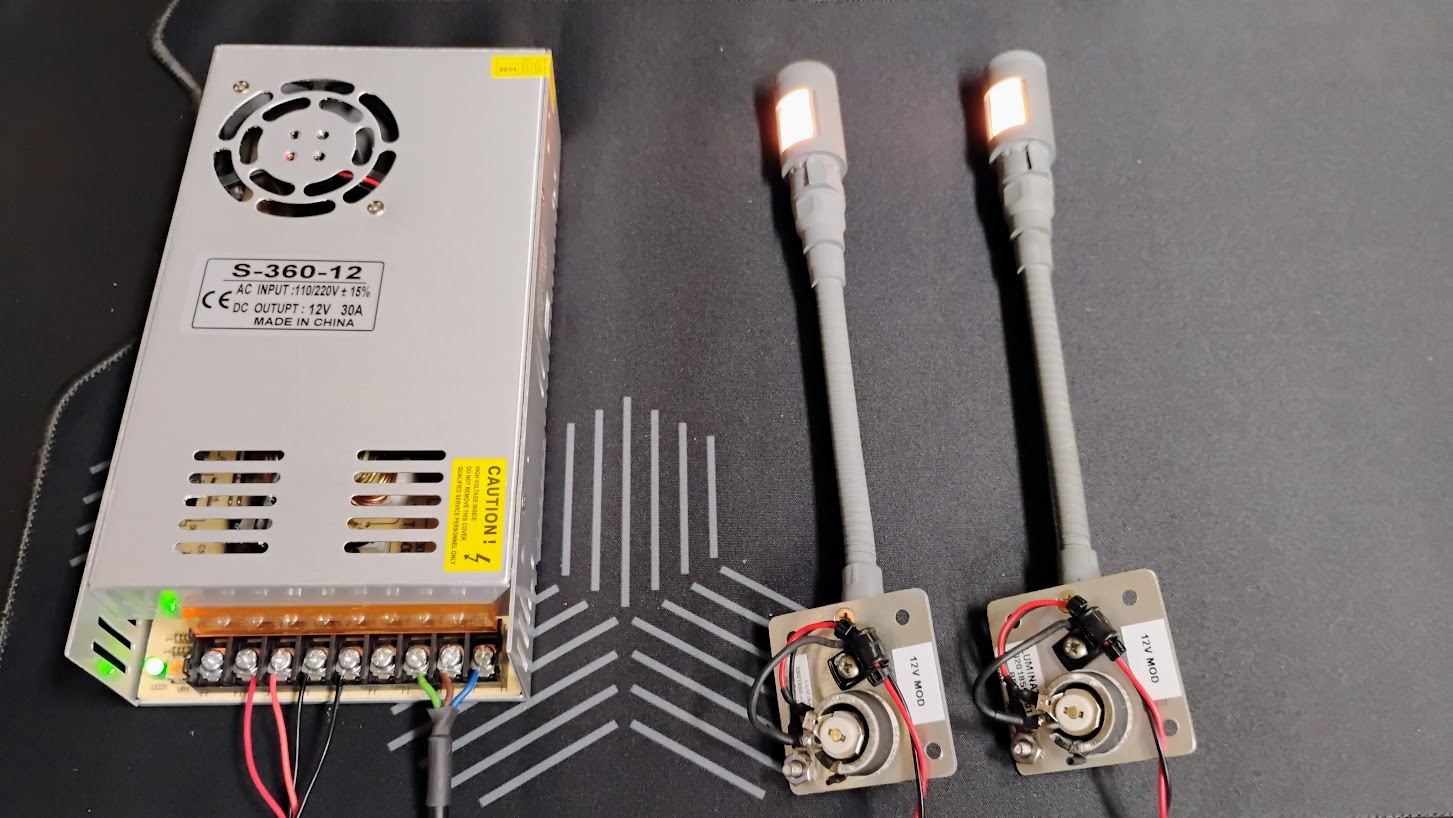
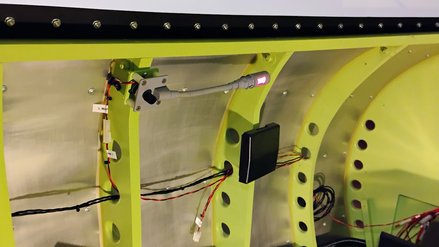
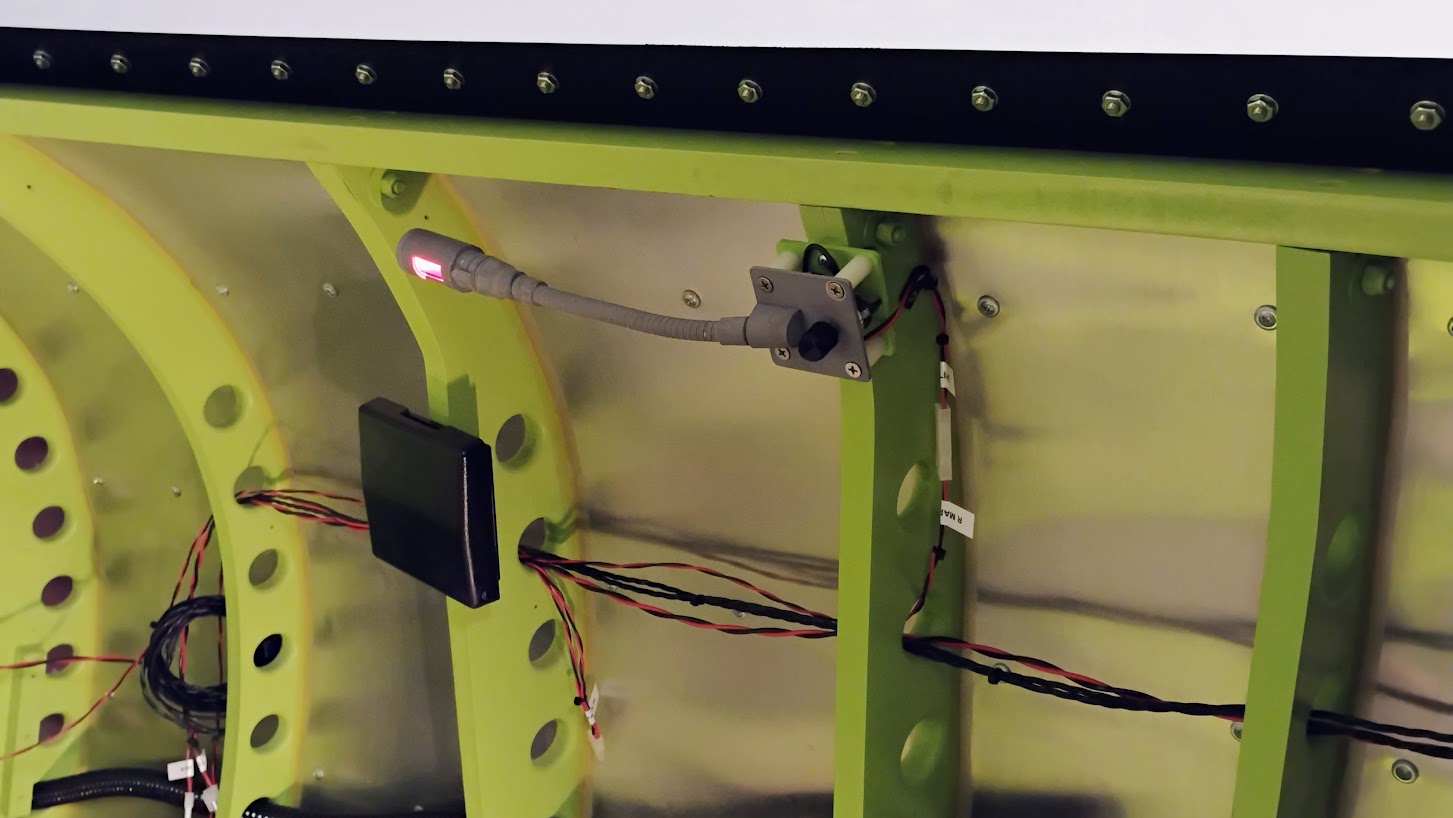
![]()
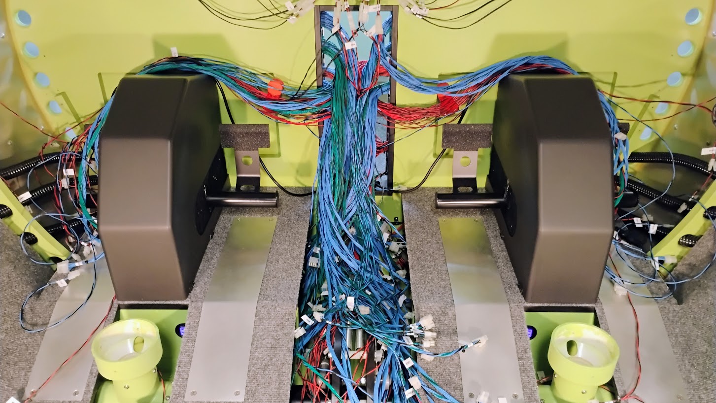
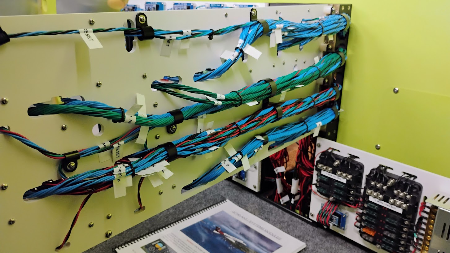
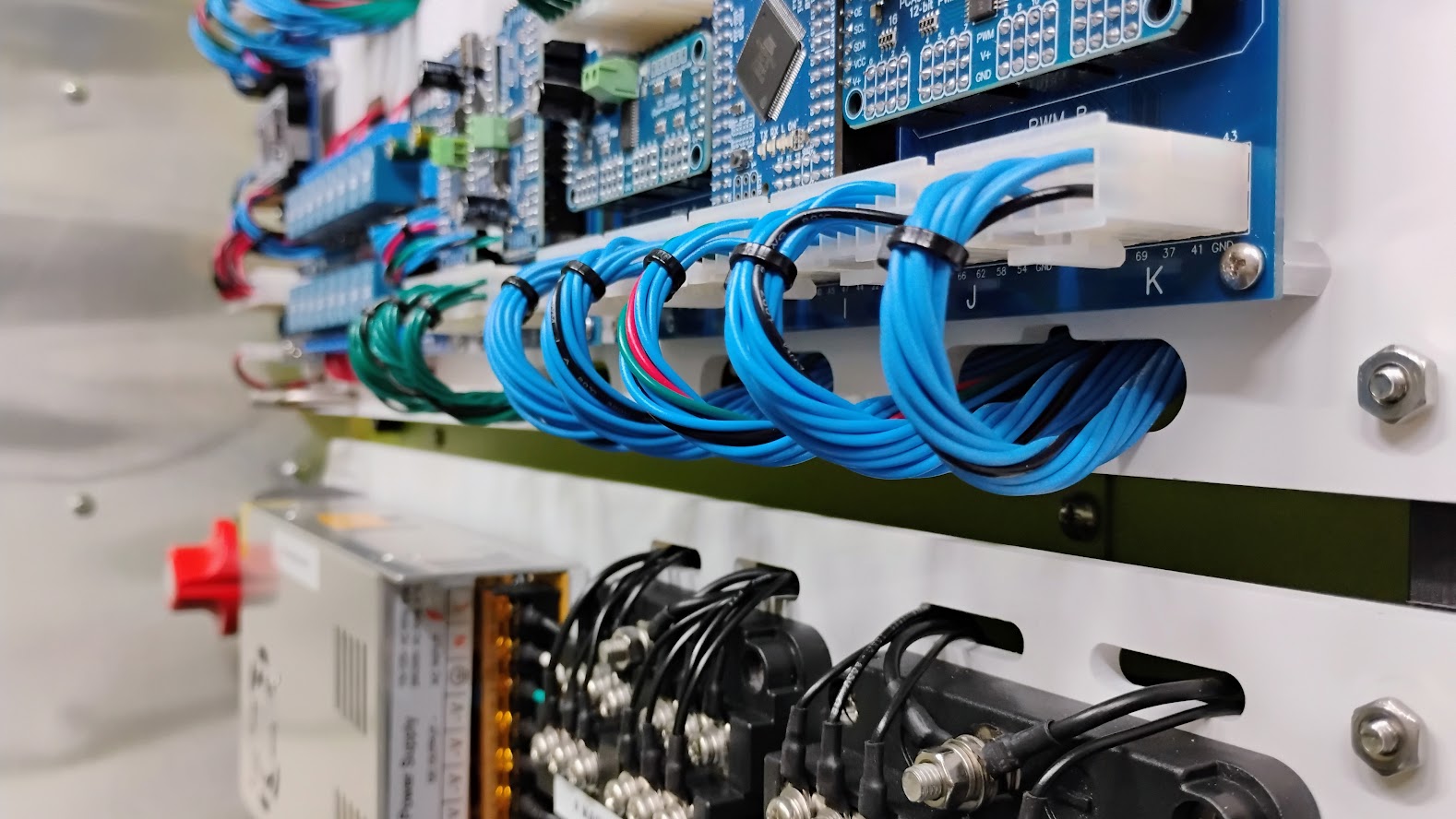
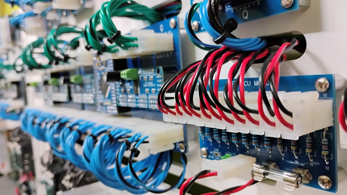
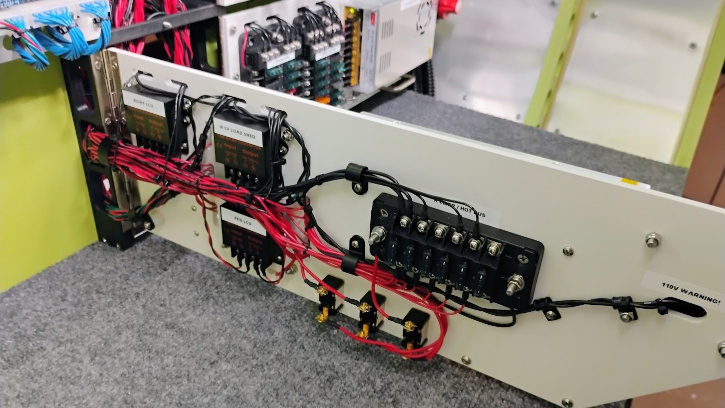
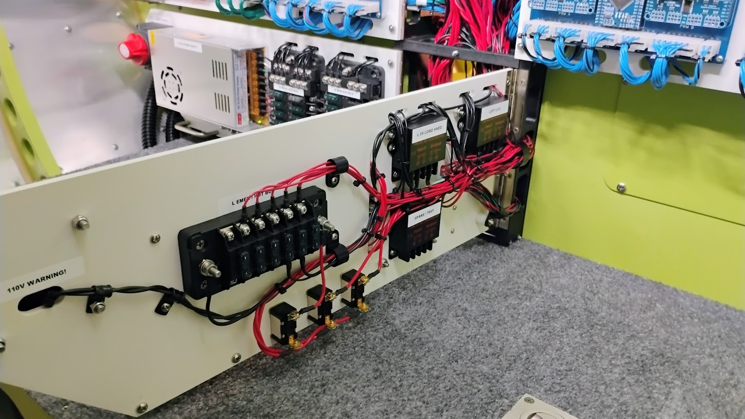
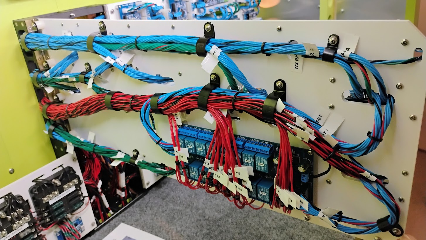
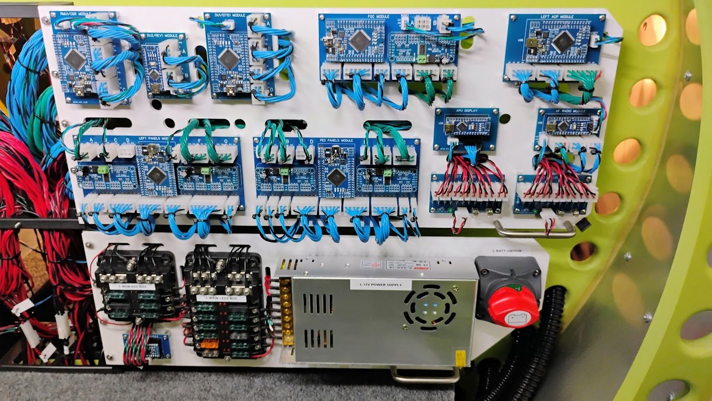
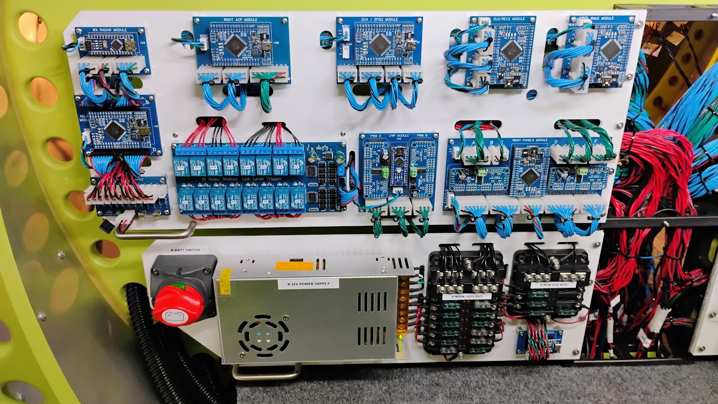
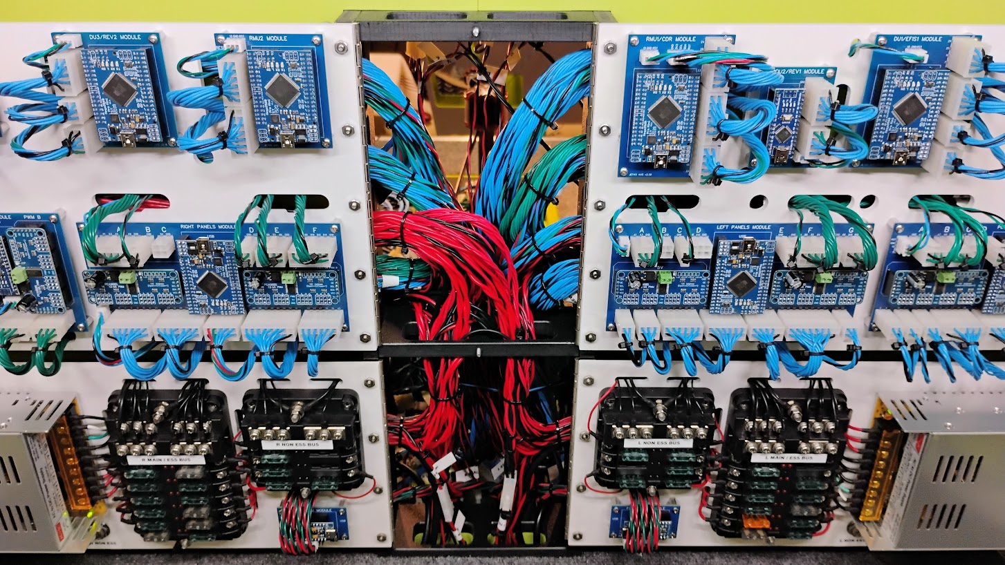
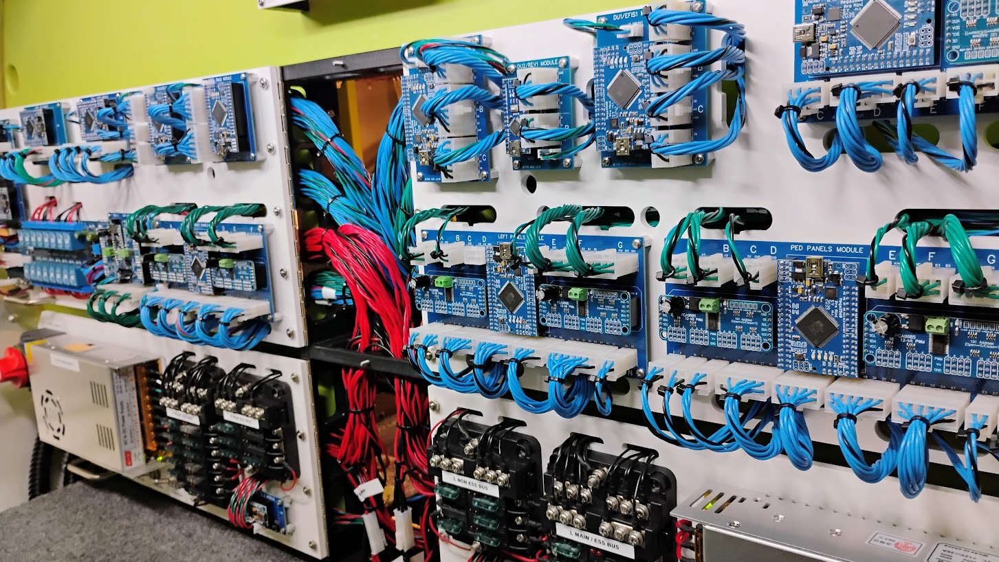
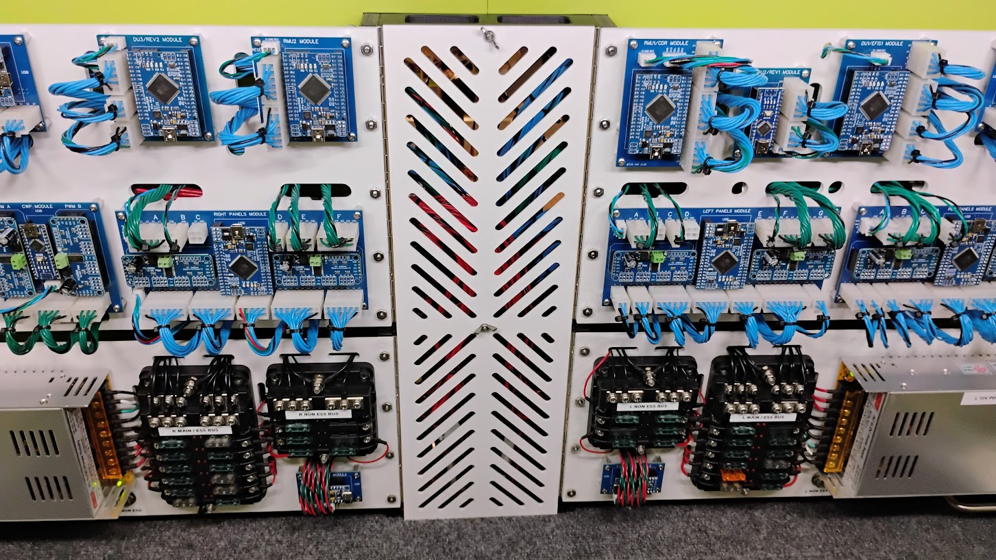
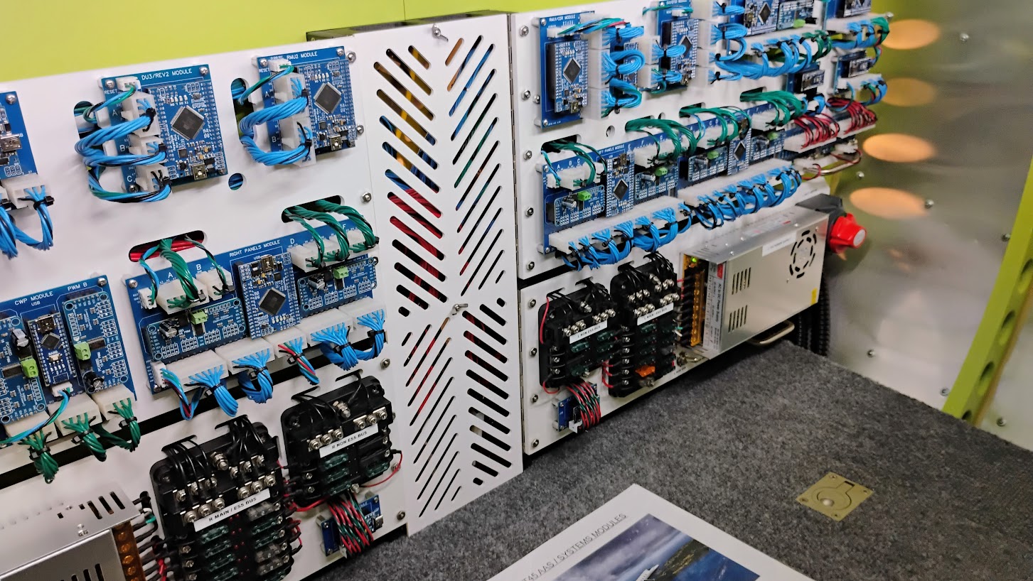
![]()
Forum NavigationAvionics Bay and Components v2.0
![]() #11 · January 14, 2023, 11:48 am
#11 · January 14, 2023, 11:48 am![]() #12 · May 6, 2023, 2:35 pm
#12 · May 6, 2023, 2:35 pm![]() #13 · May 7, 2023, 1:28 am
#13 · May 7, 2023, 1:28 am![]() #14 · May 7, 2023, 12:13 pm
#14 · May 7, 2023, 12:13 pm![]() #15 · June 14, 2024, 11:13 pm
#15 · June 14, 2024, 11:13 pm![]() #16 · July 18, 2024, 8:04 pm
#16 · July 18, 2024, 8:04 pm![]() #17 · June 1, 2025, 1:03 pmHunkaBurninLove, Mark Speechley and Roel have reacted to this post.HunkaBurninLoveMark SpeechleyRoel
#17 · June 1, 2025, 1:03 pmHunkaBurninLove, Mark Speechley and Roel have reacted to this post.HunkaBurninLoveMark SpeechleyRoel![]() #18 · June 28, 2025, 1:39 amHunkaBurninLove and Mark Speechley have reacted to this post.HunkaBurninLoveMark Speechley
#18 · June 28, 2025, 1:39 amHunkaBurninLove and Mark Speechley have reacted to this post.HunkaBurninLoveMark Speechley![]() #19 · August 26, 2025, 1:58 pmMark Speechley has reacted to this post.Mark Speechley
#19 · August 26, 2025, 1:58 pmMark Speechley has reacted to this post.Mark Speechley![]() #20 · August 26, 2025, 9:13 pmRon Rollo has reacted to this post.Ron Rollo
#20 · August 26, 2025, 9:13 pmRon Rollo has reacted to this post.Ron Rollo
2017-10-10