


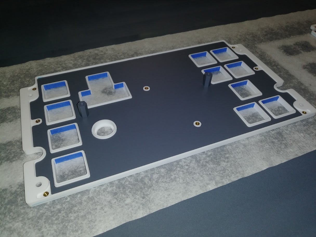
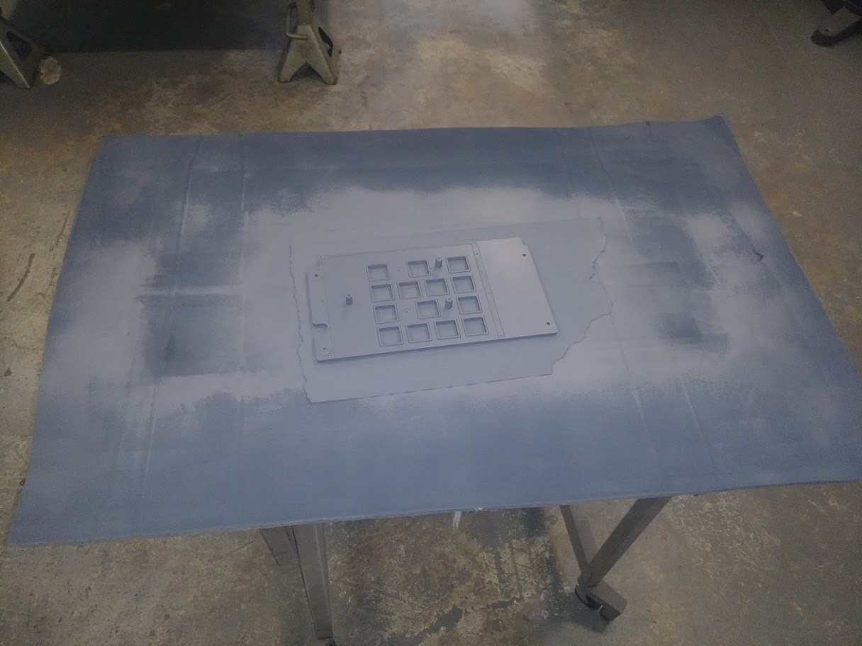
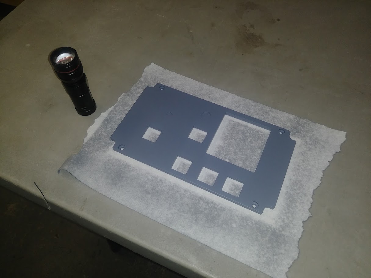
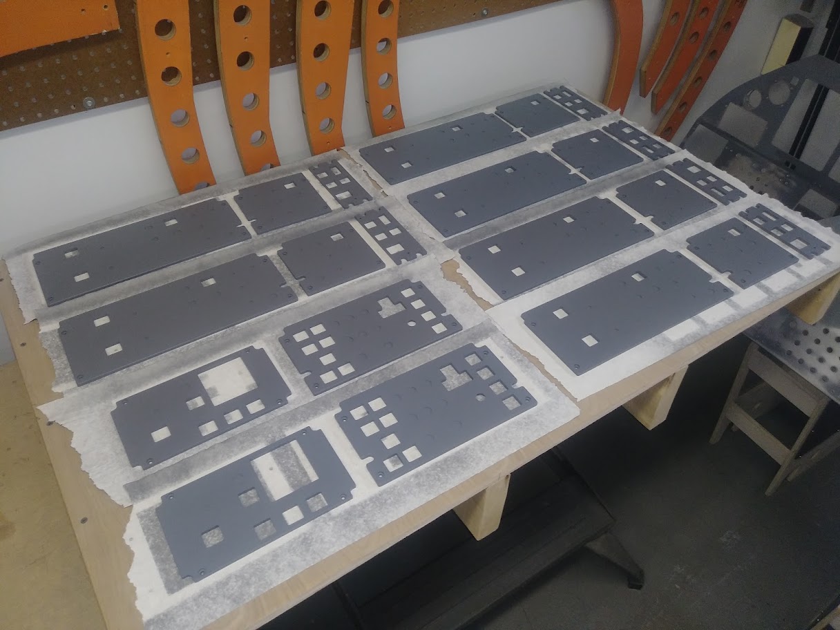
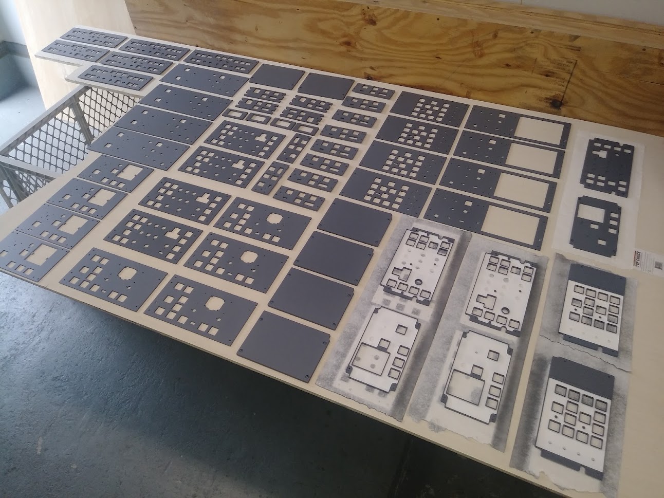
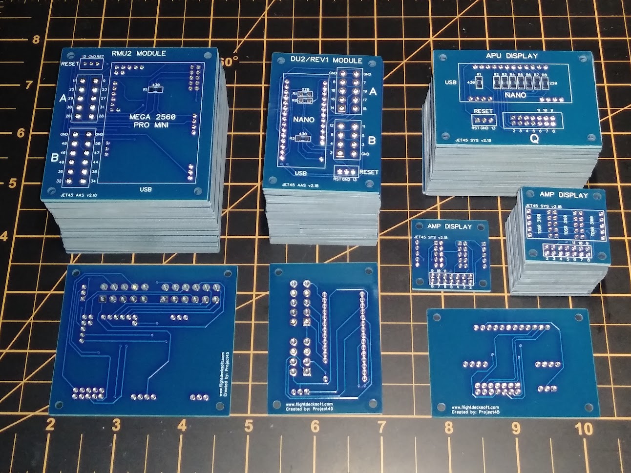
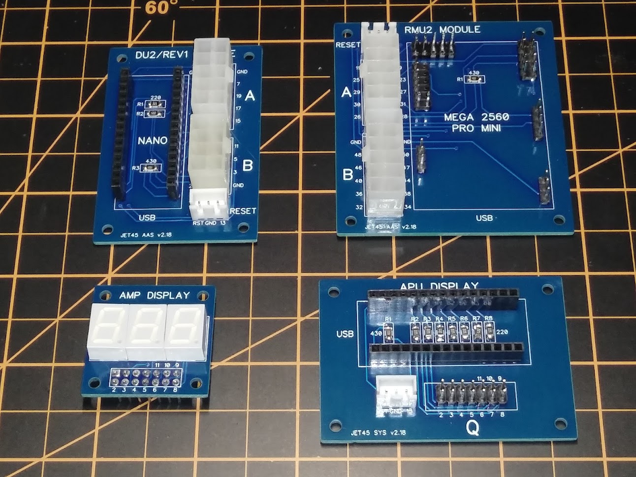
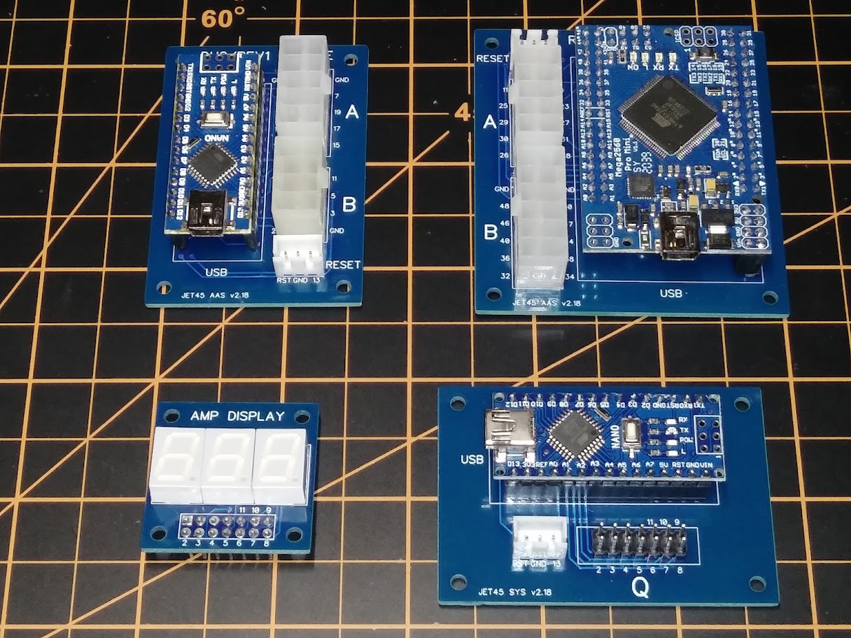
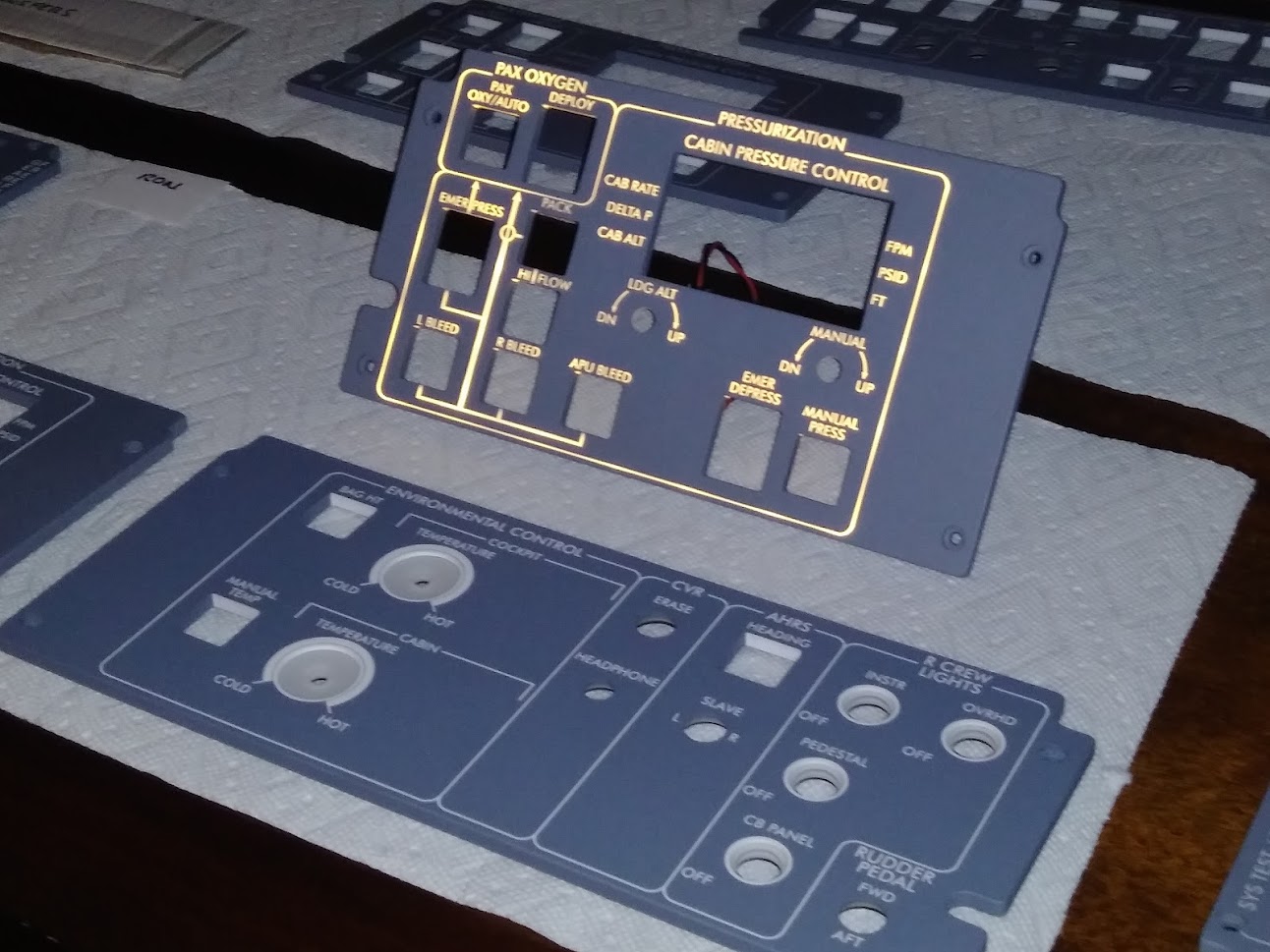
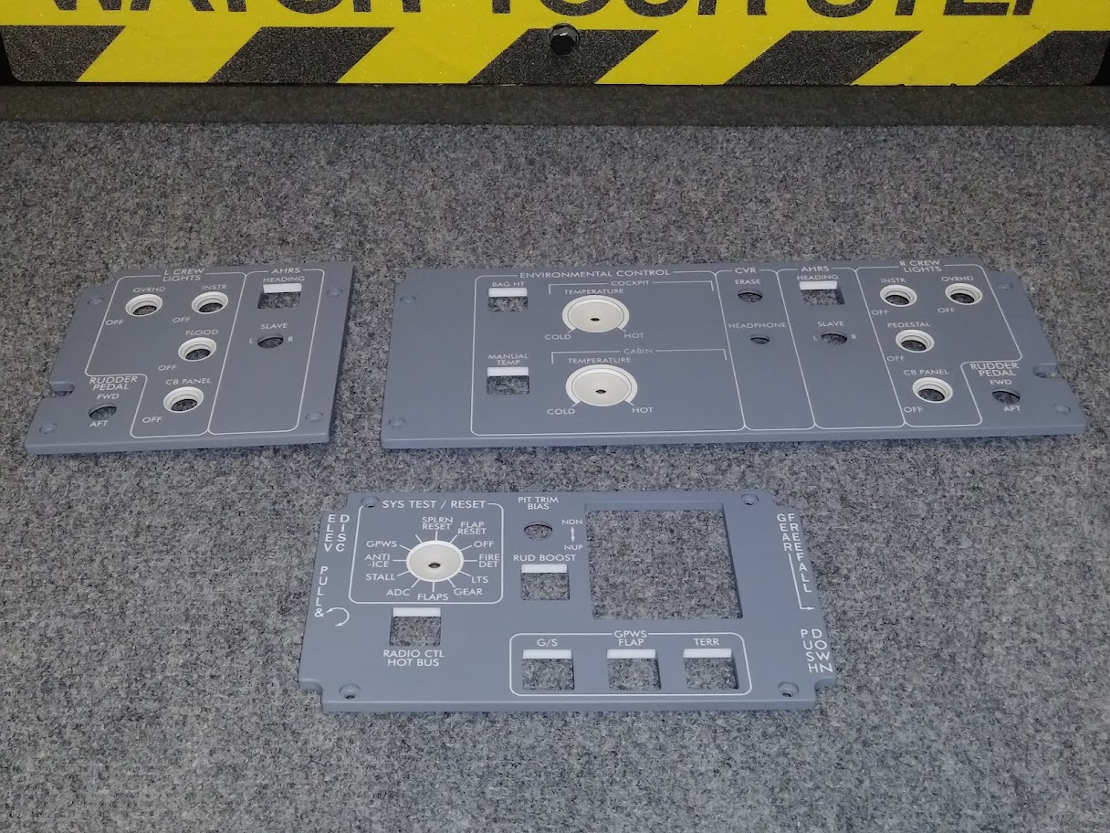
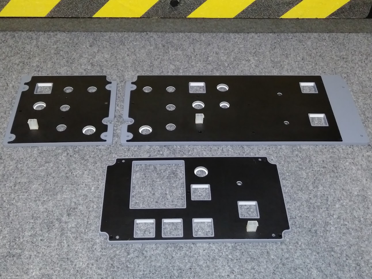
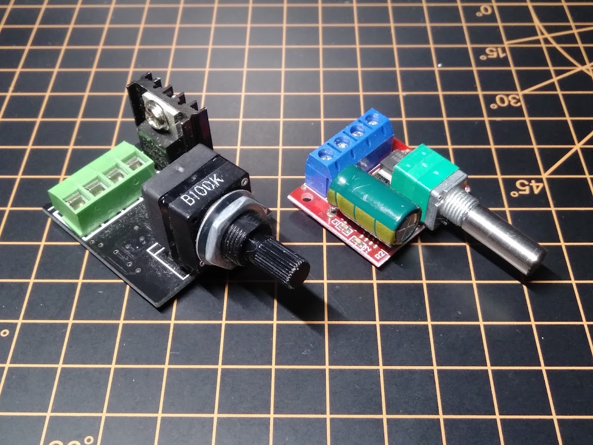
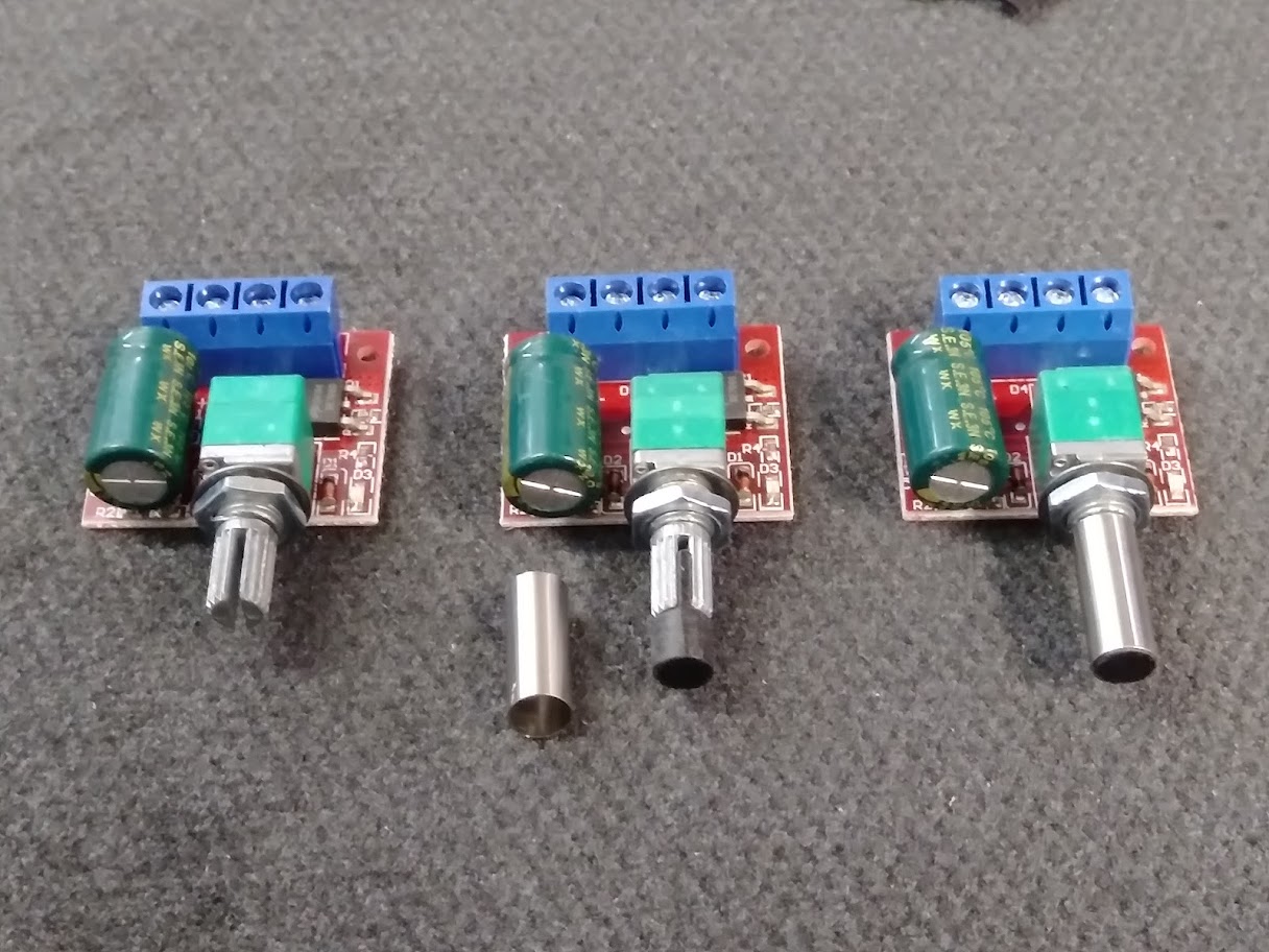
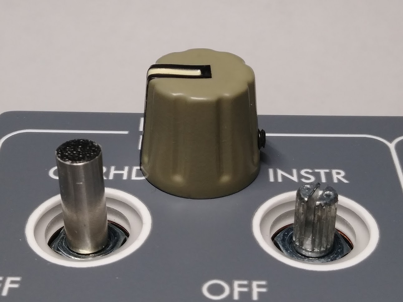
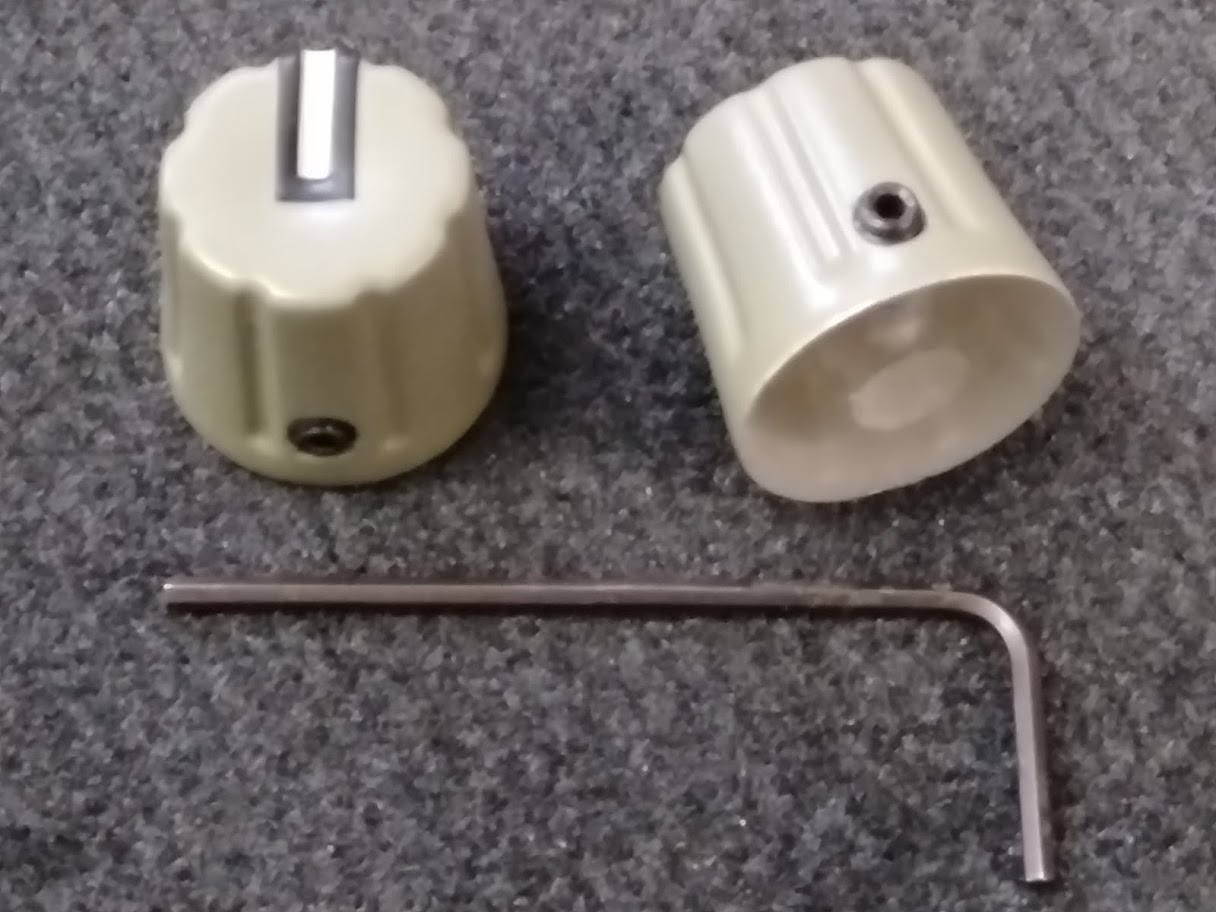
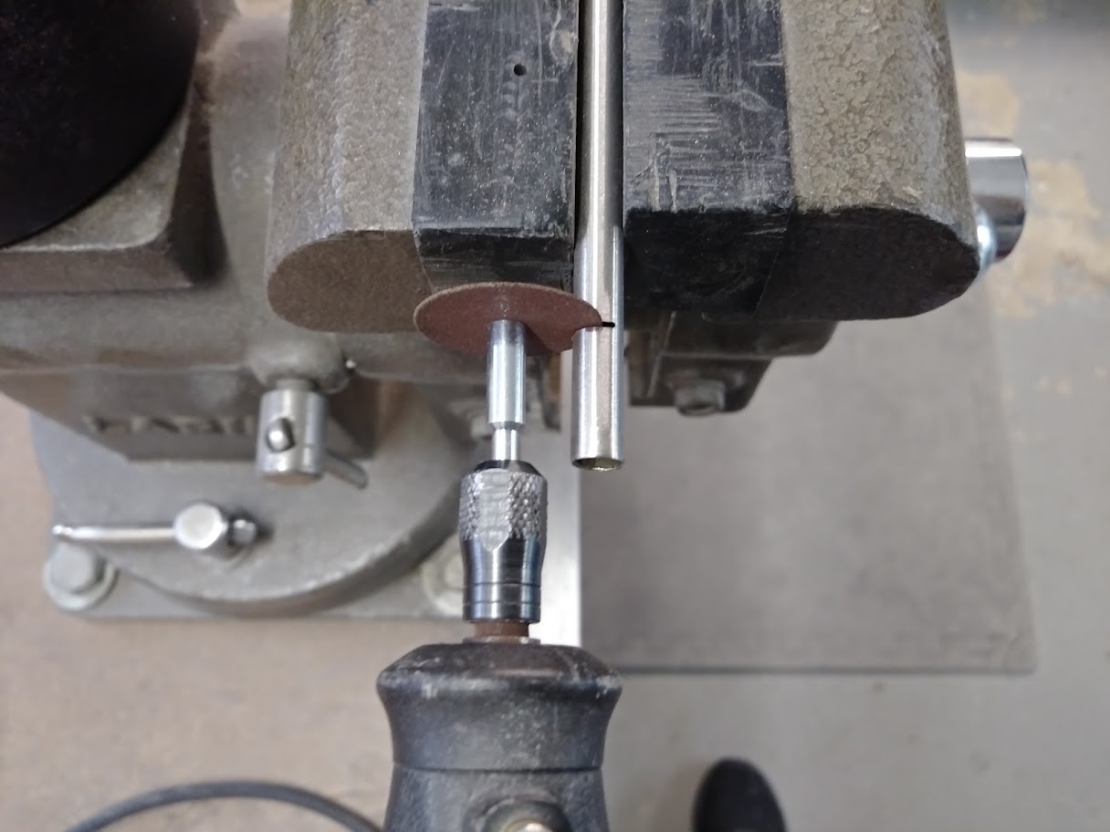
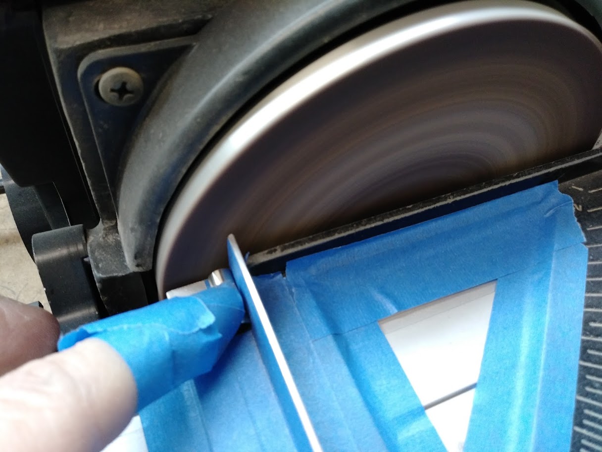
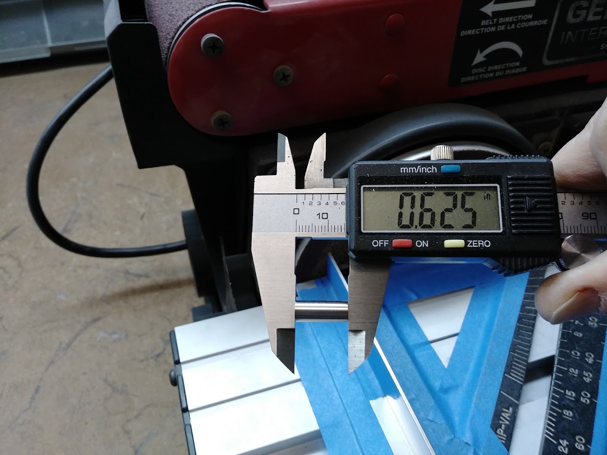
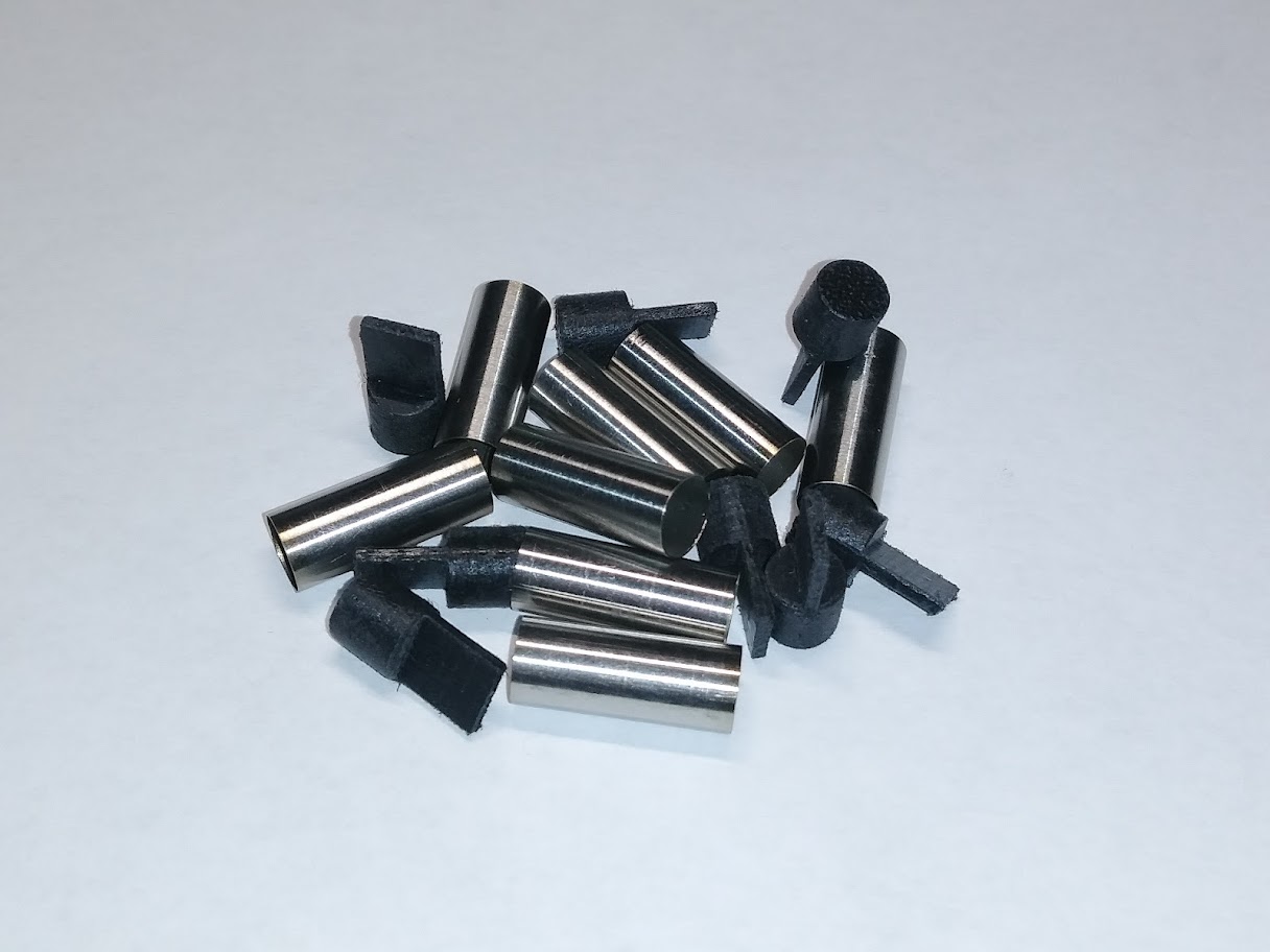
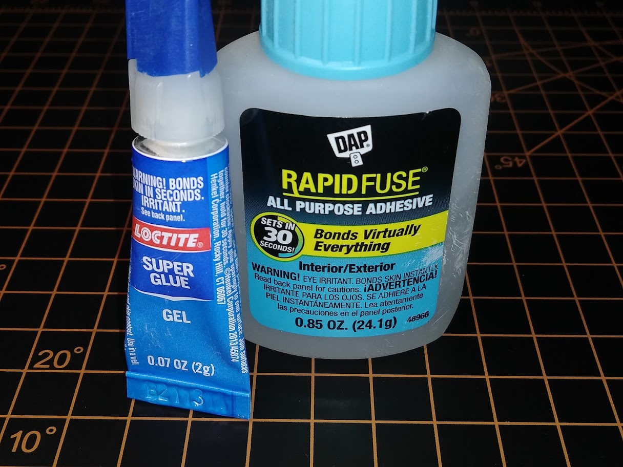
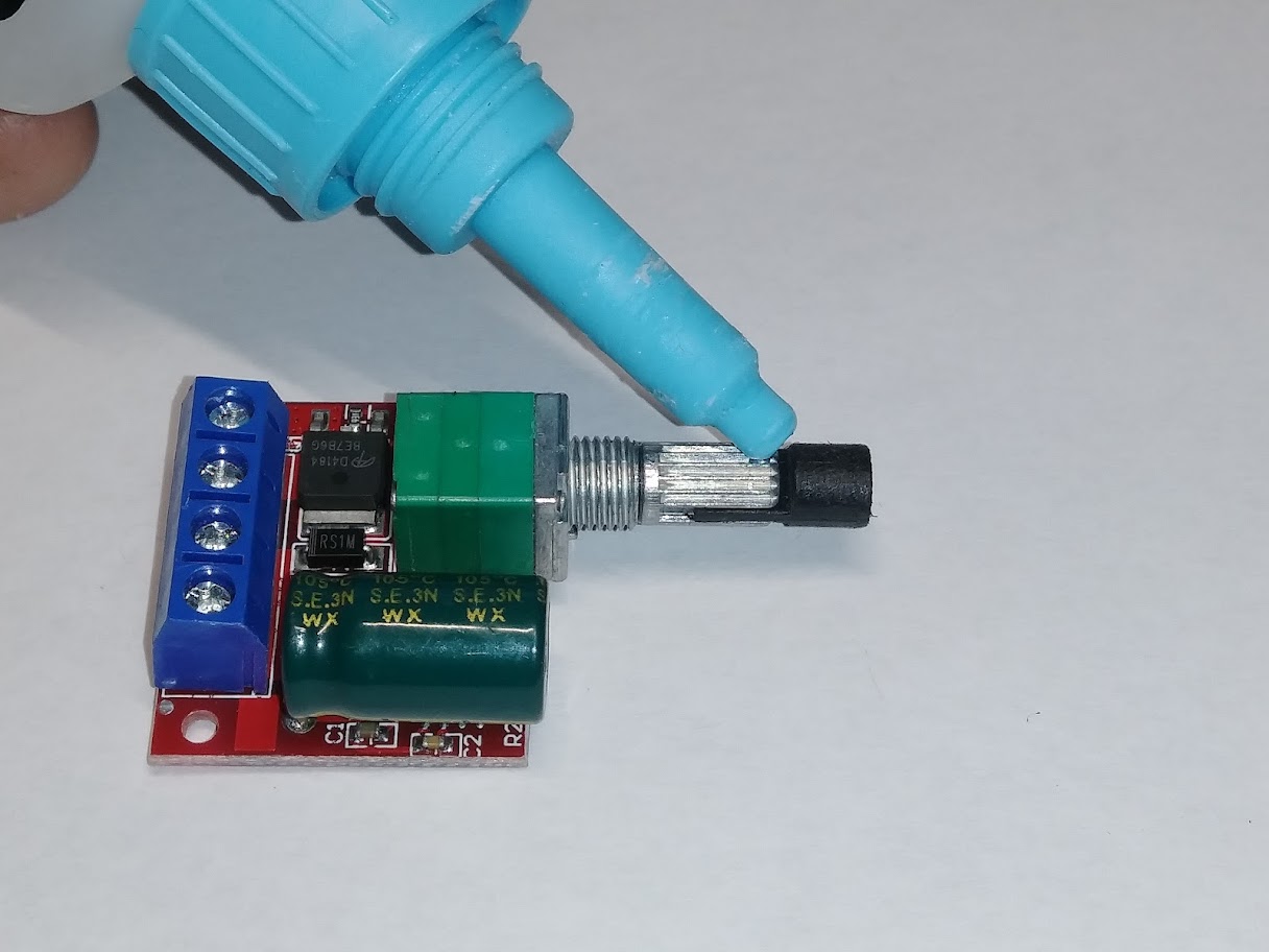
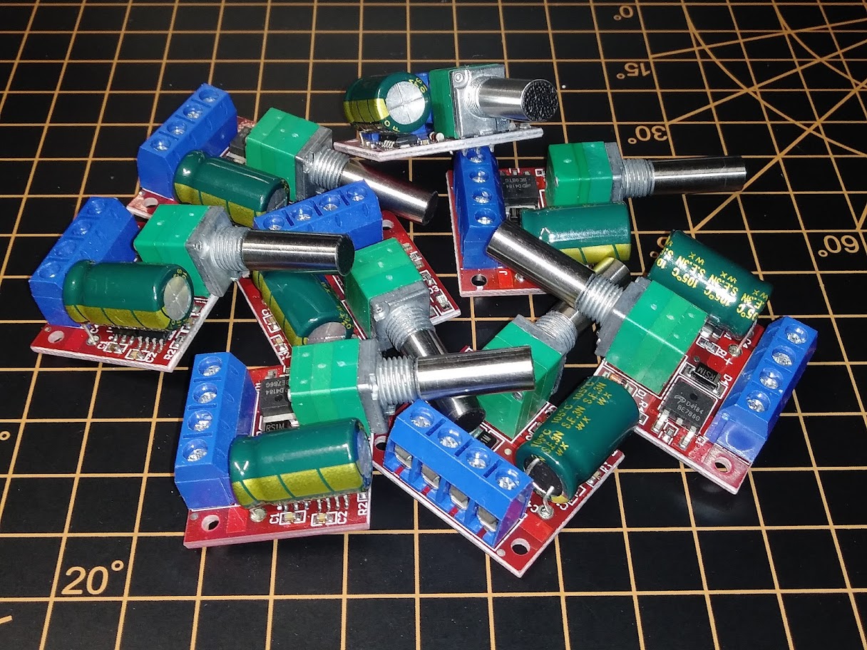
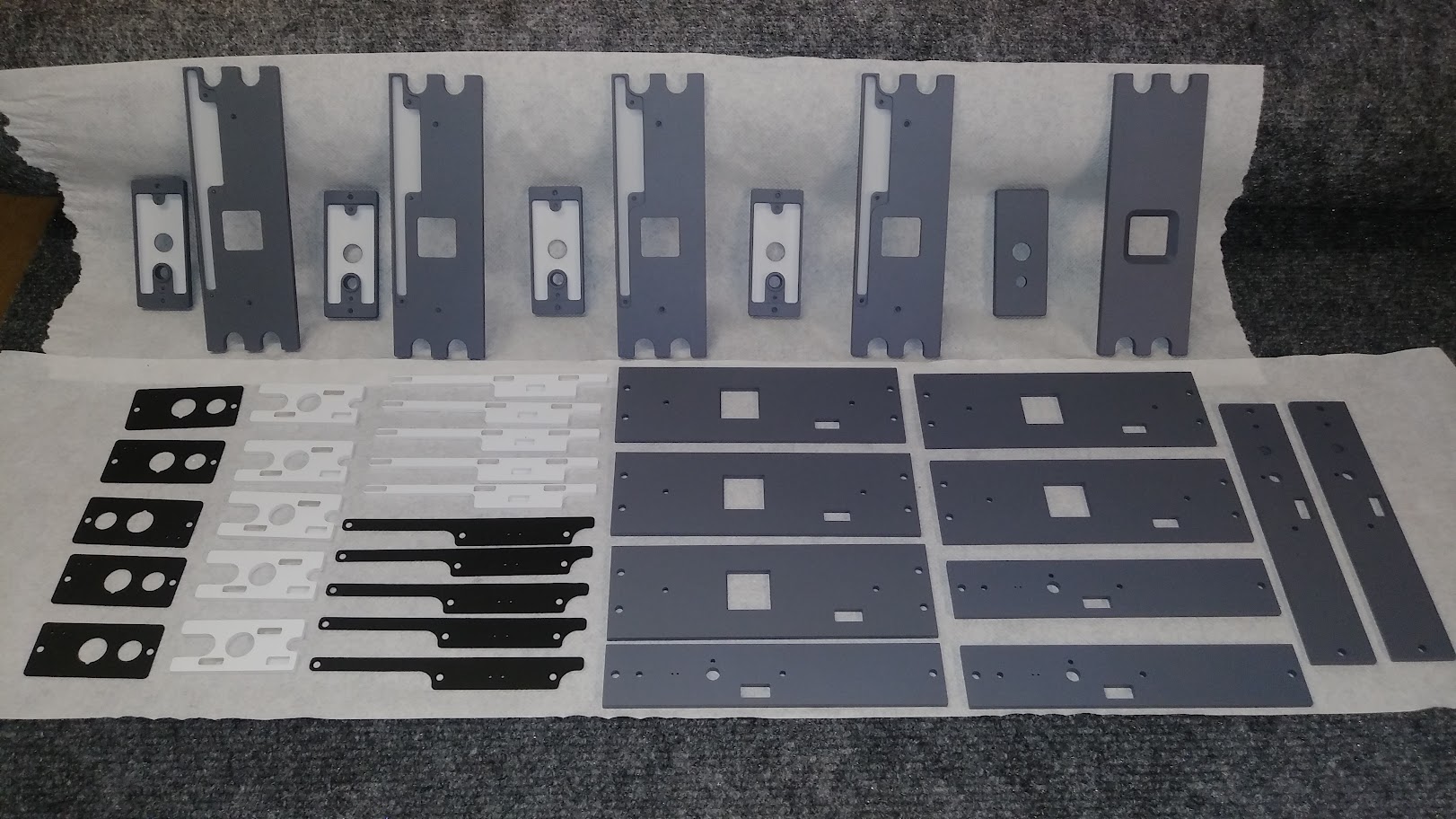
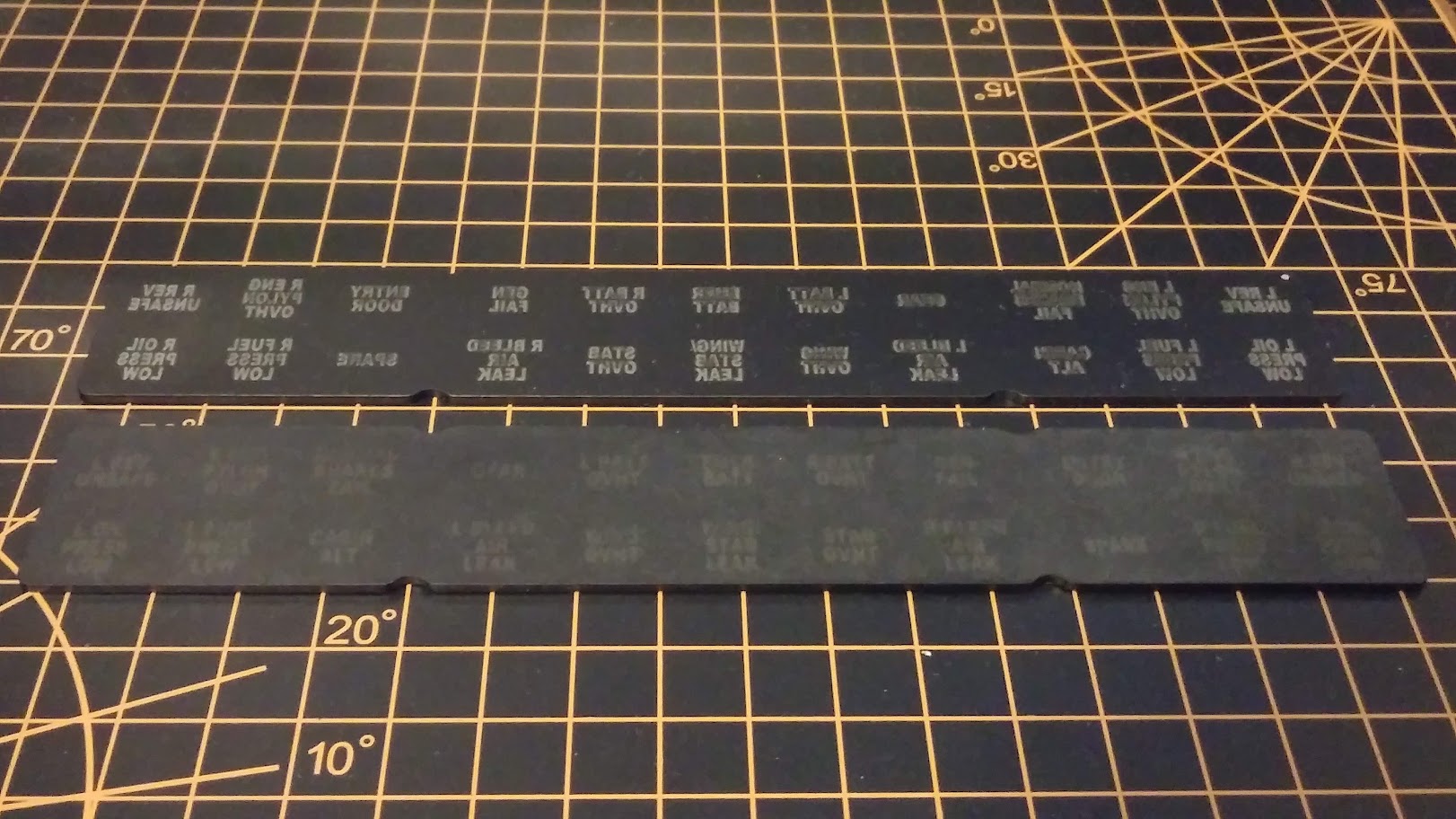
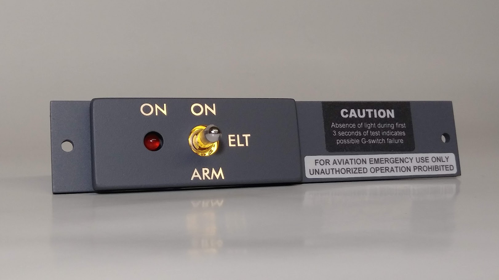
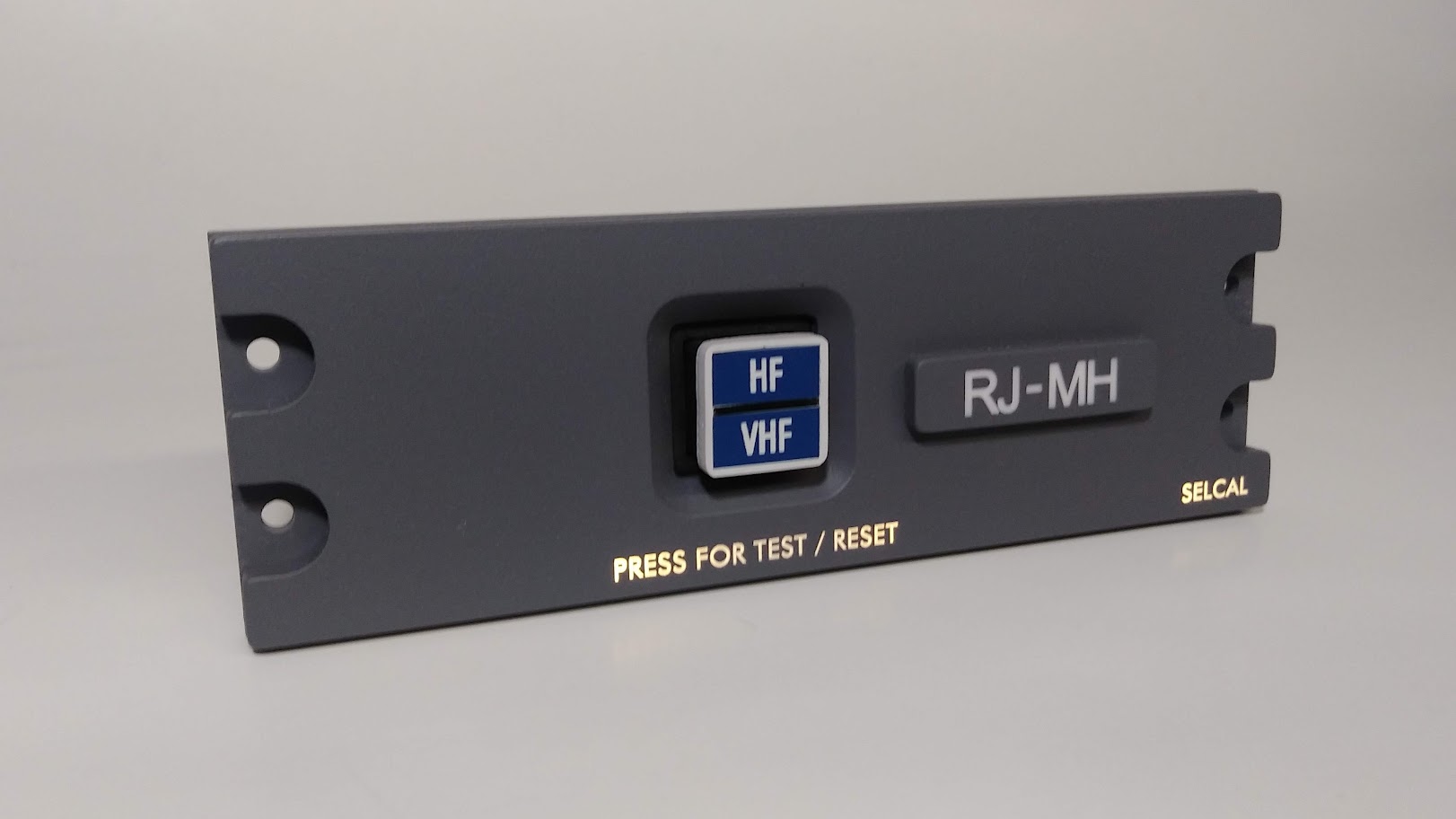
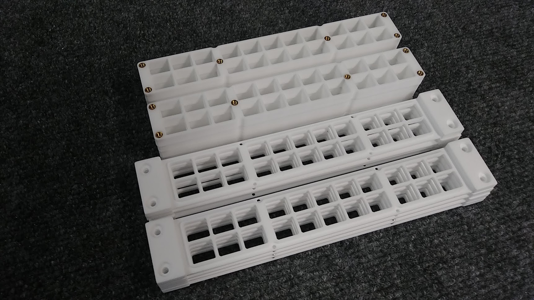
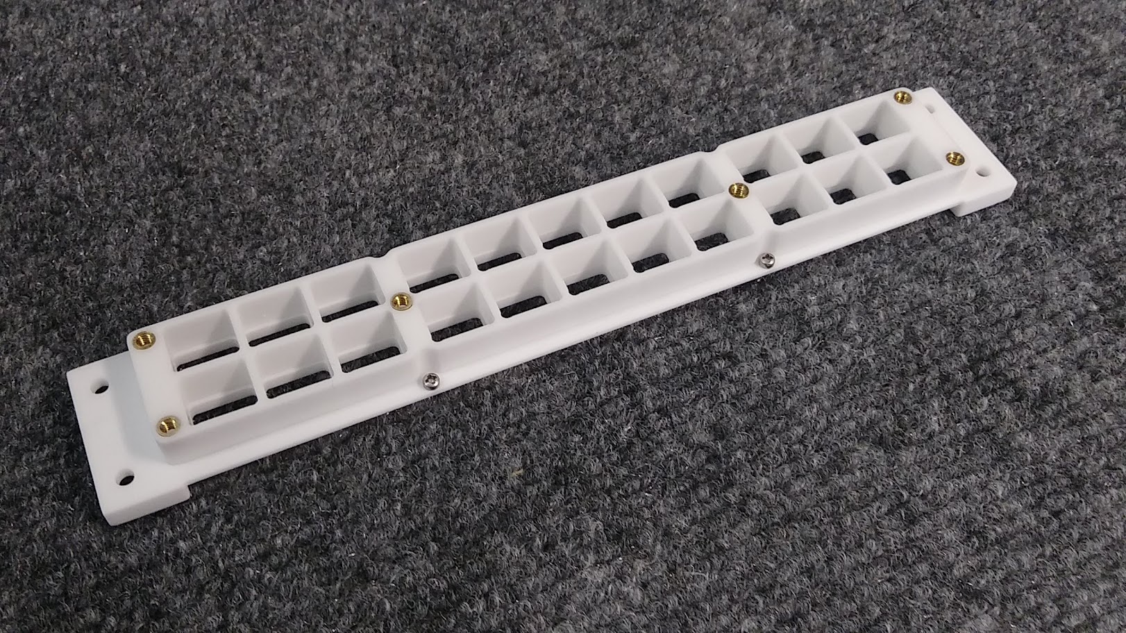
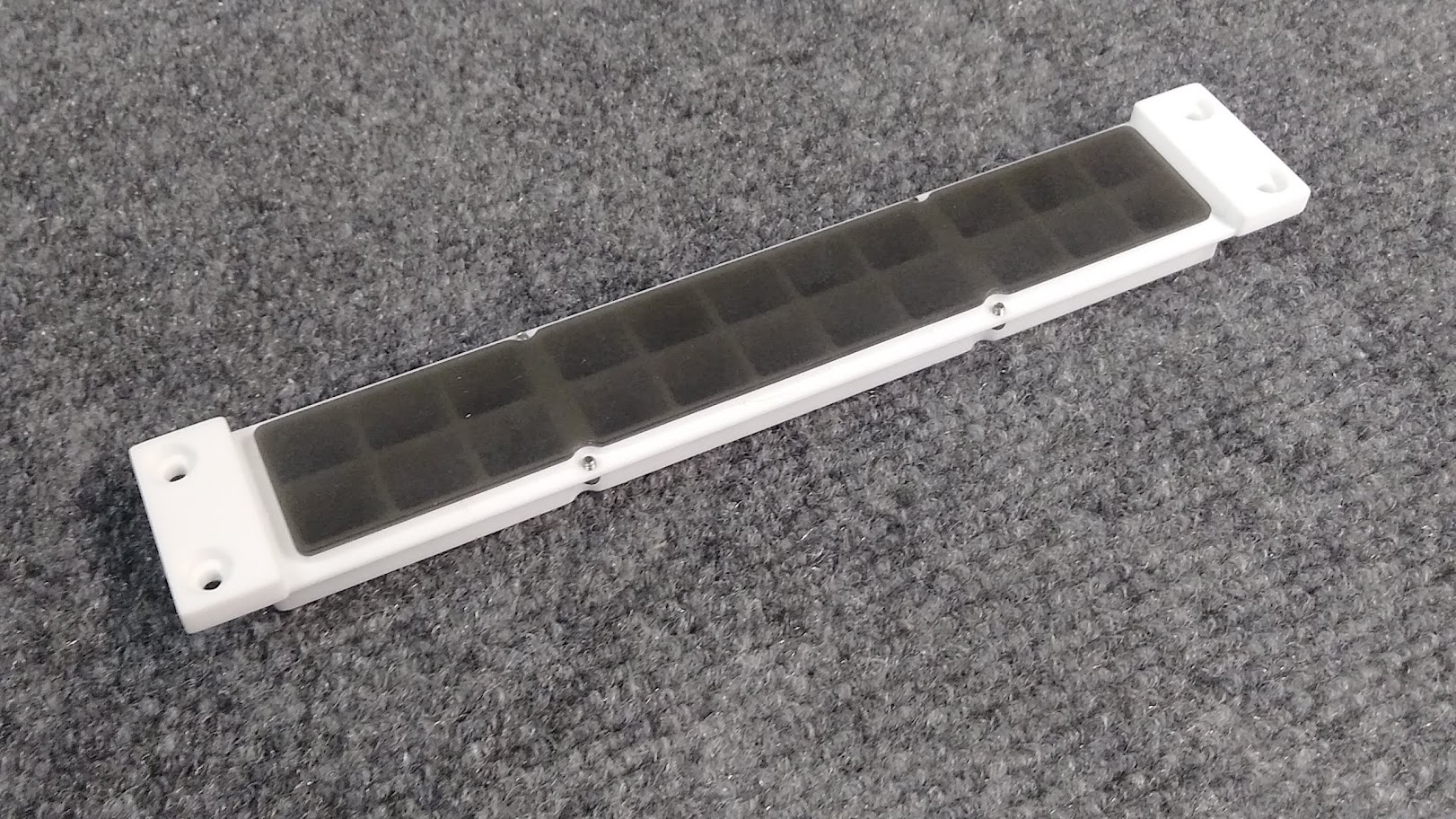
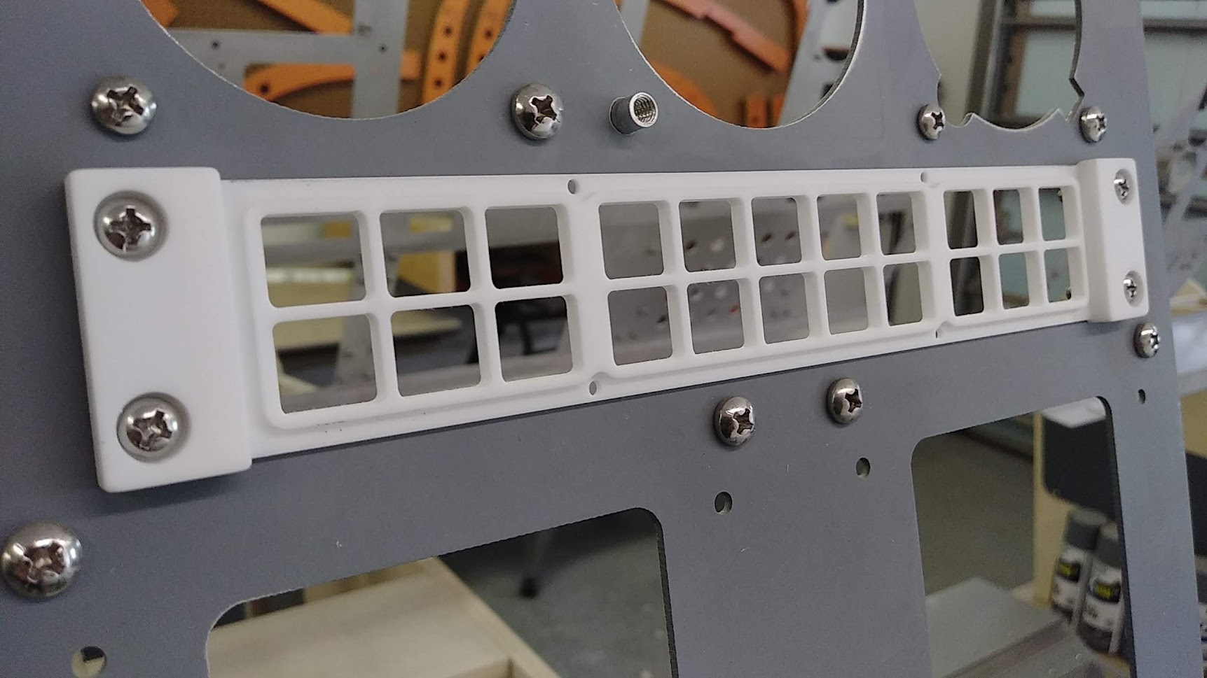
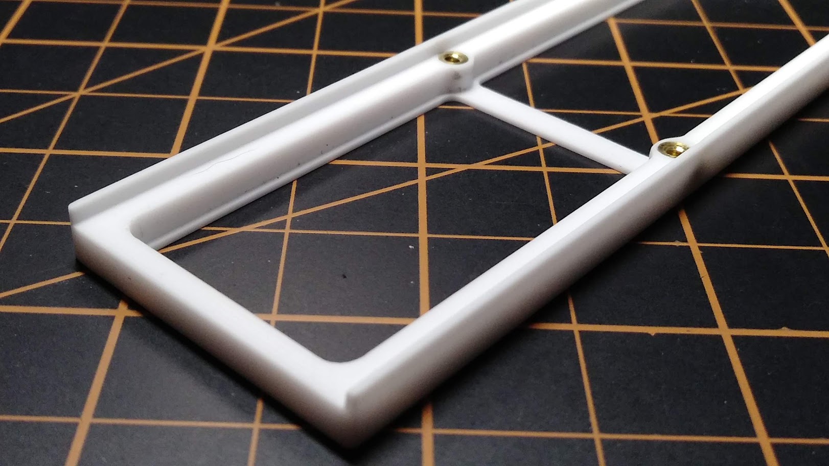
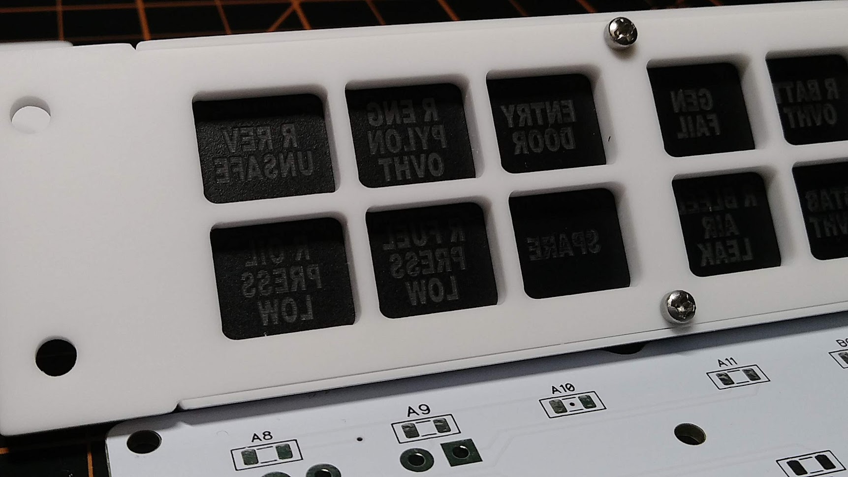
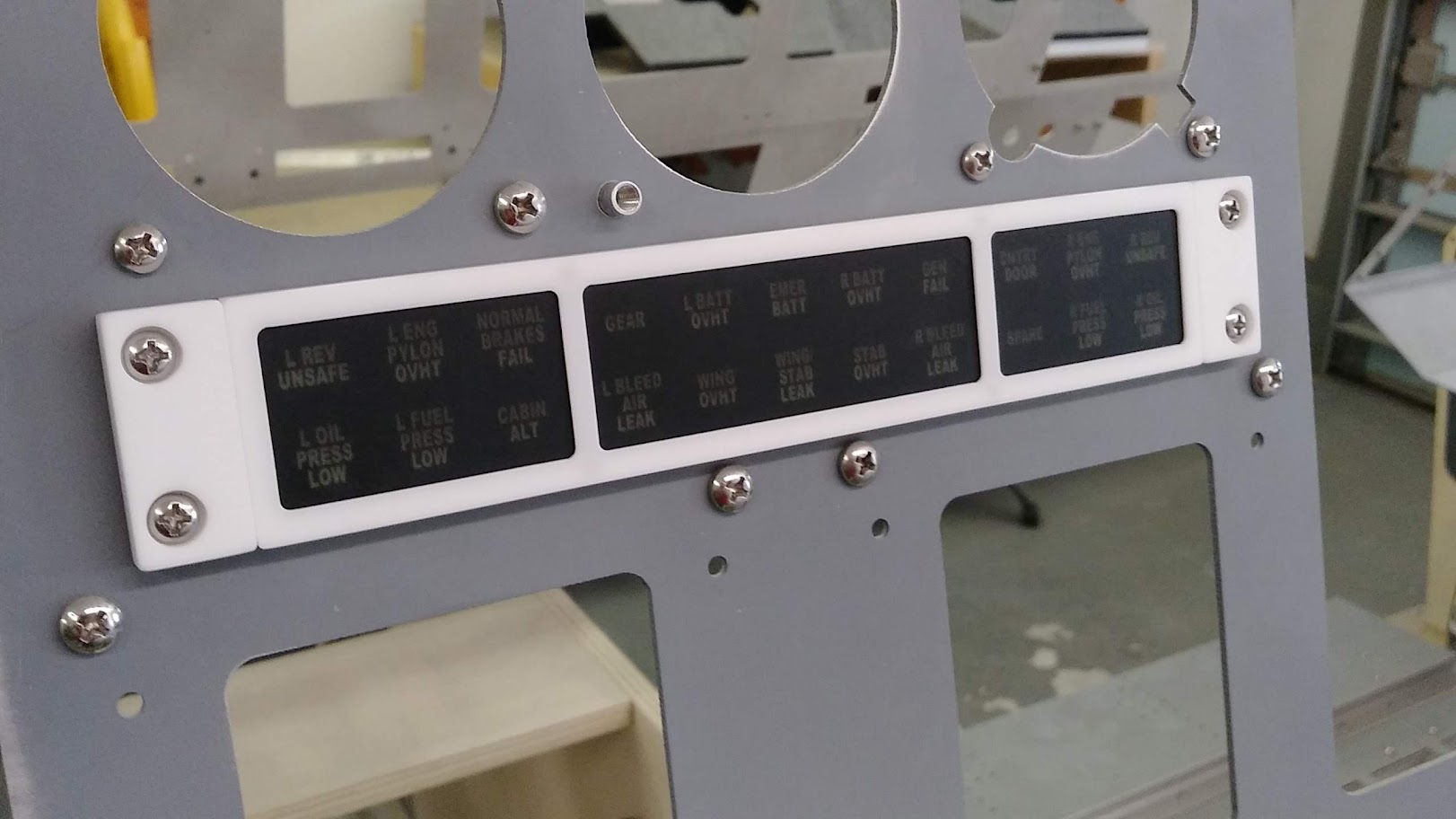
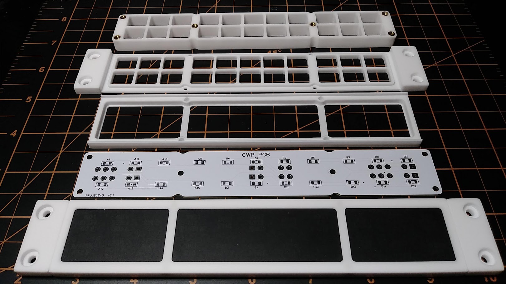
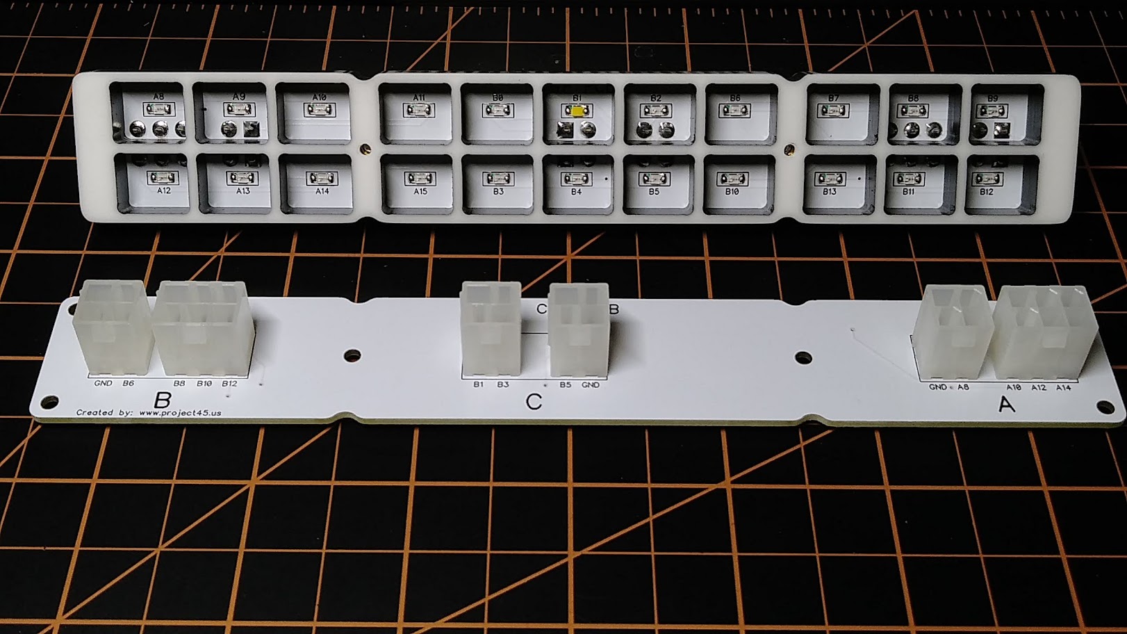
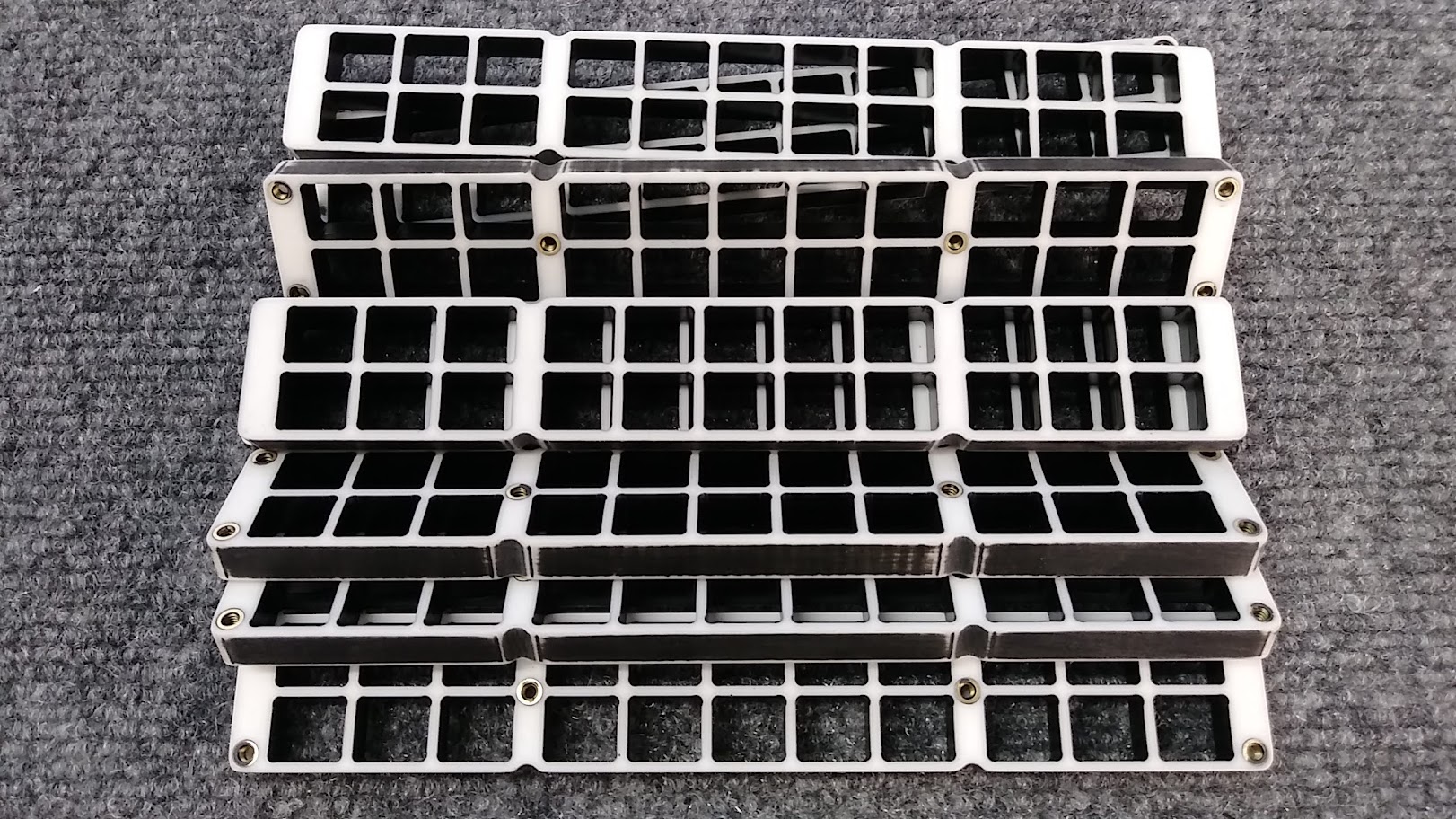
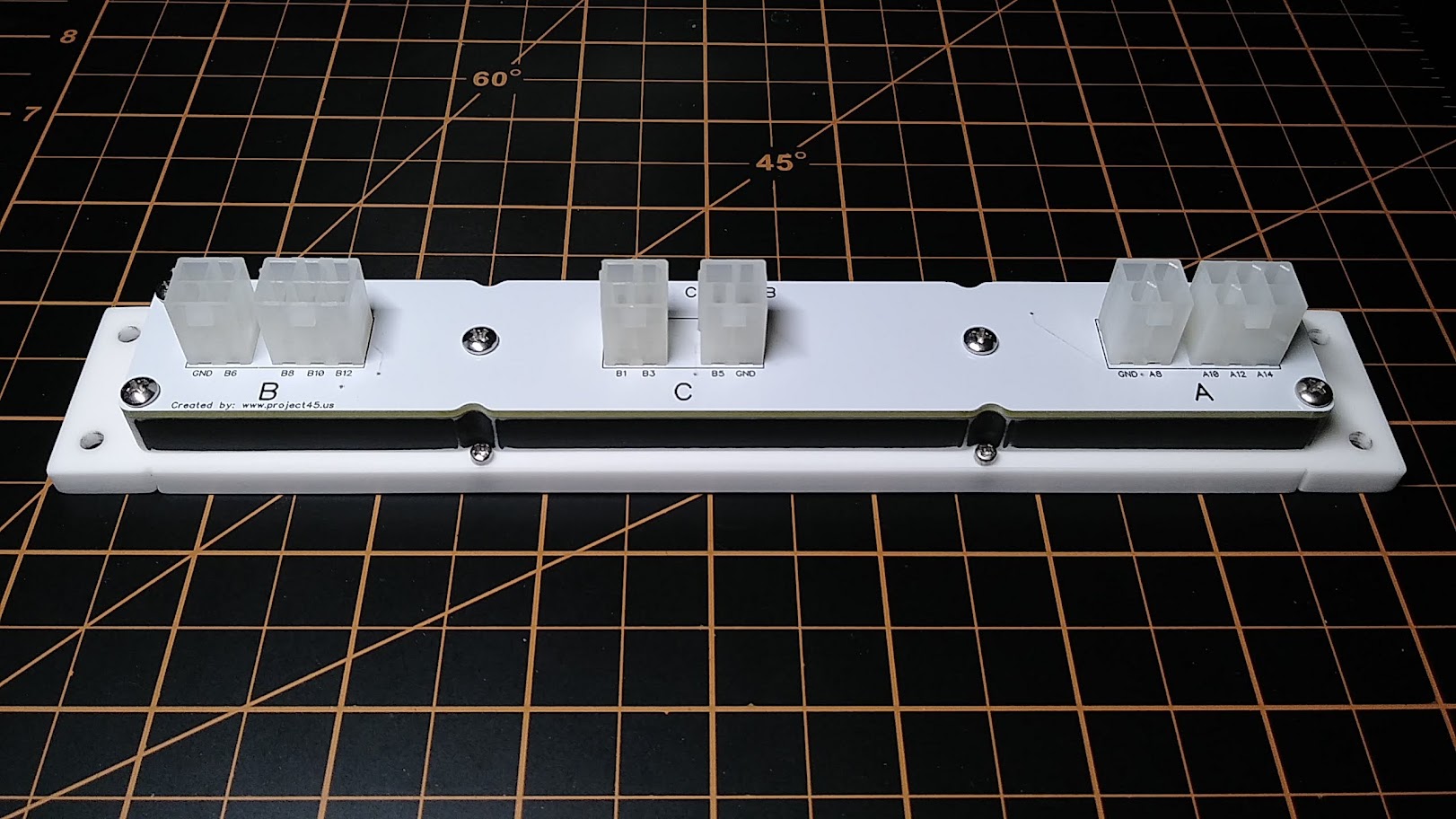
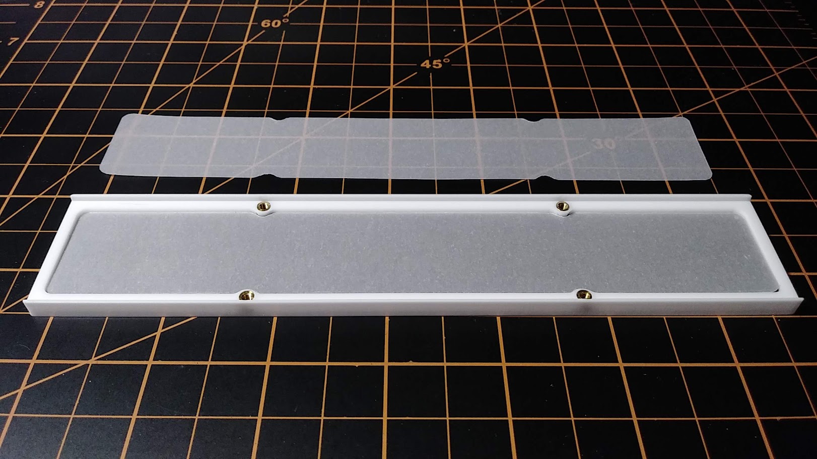
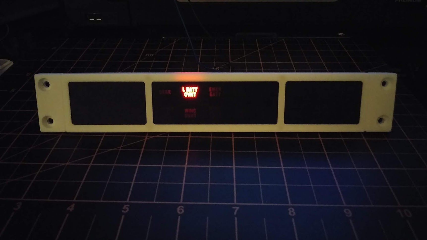
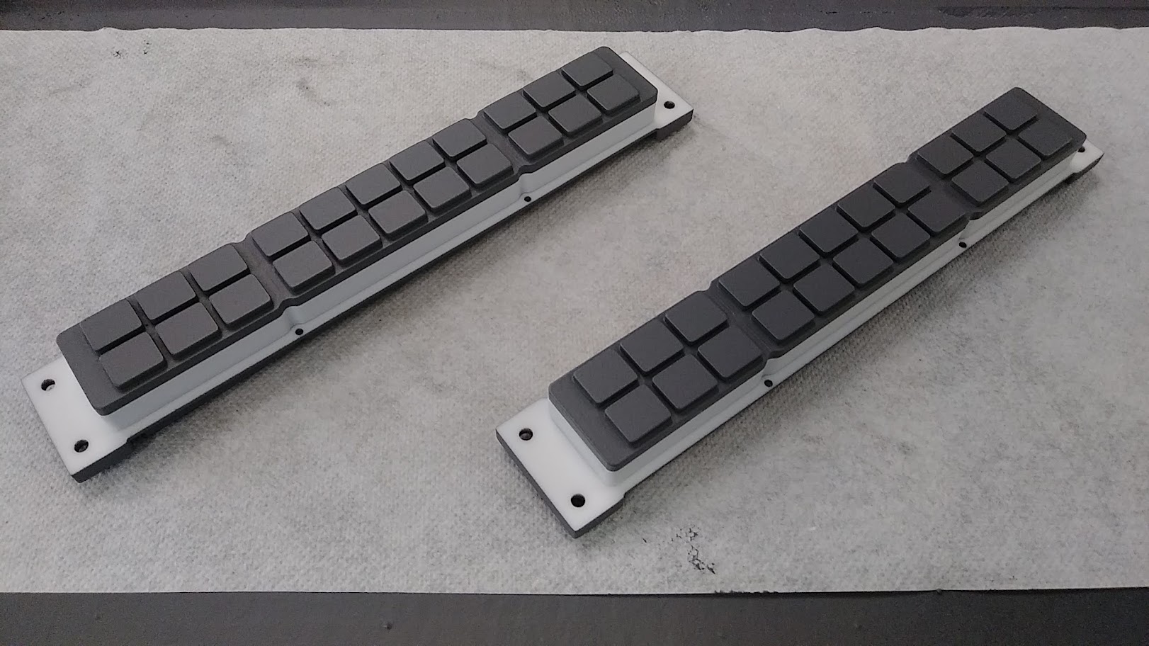
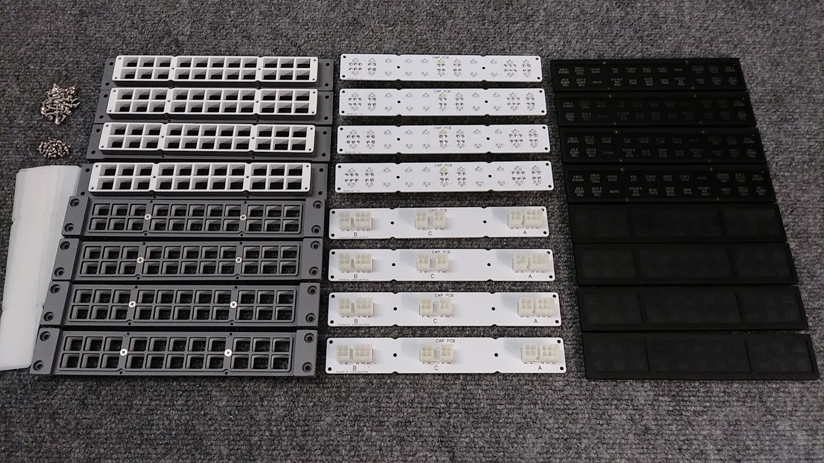
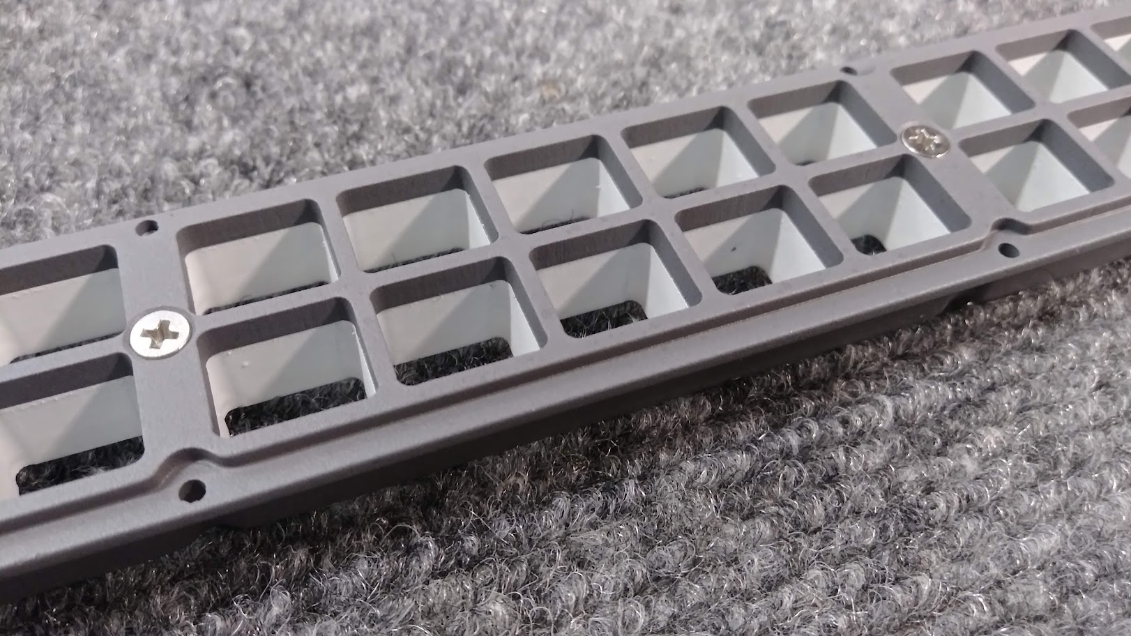
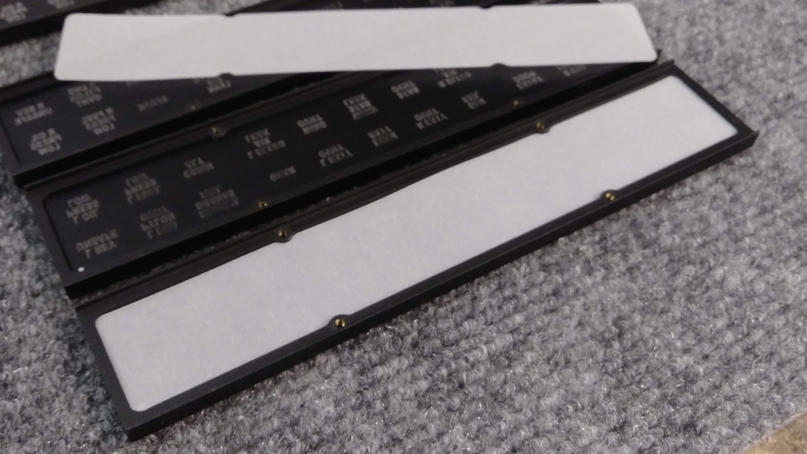
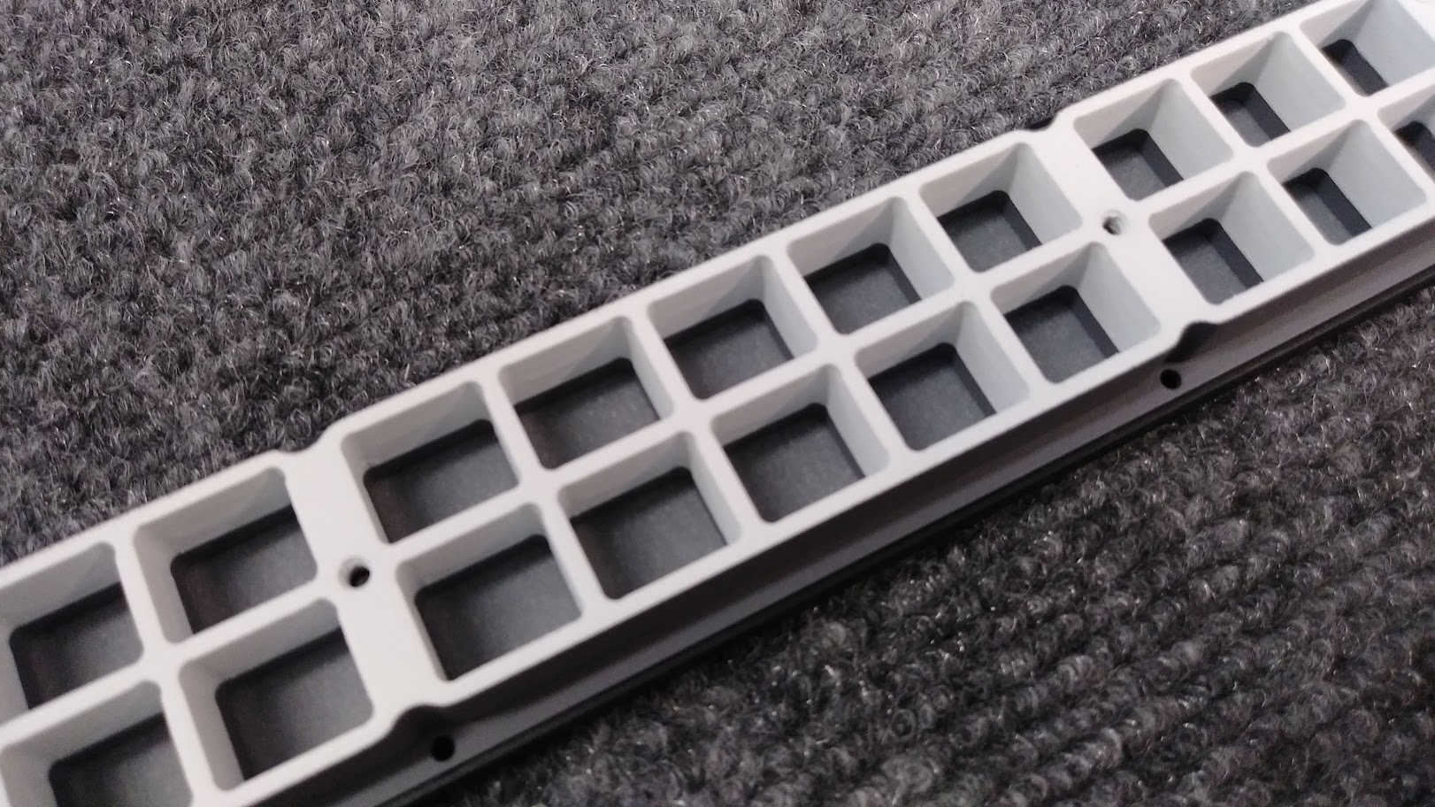
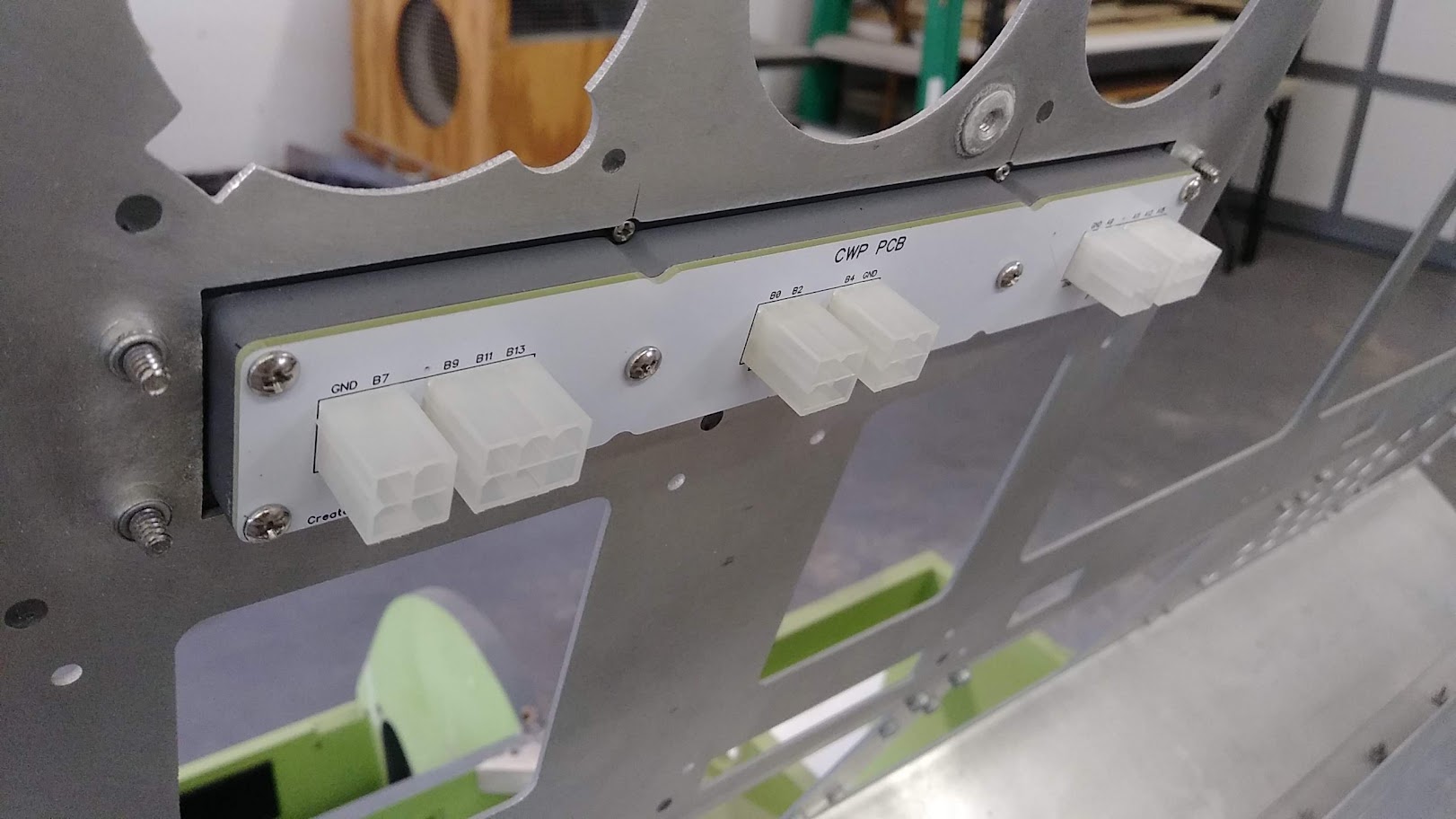
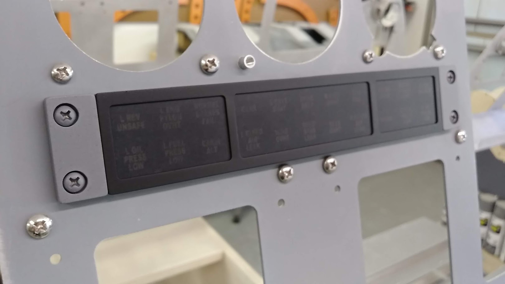
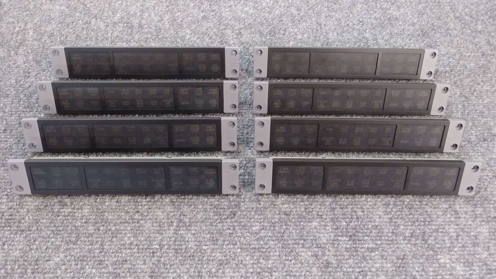
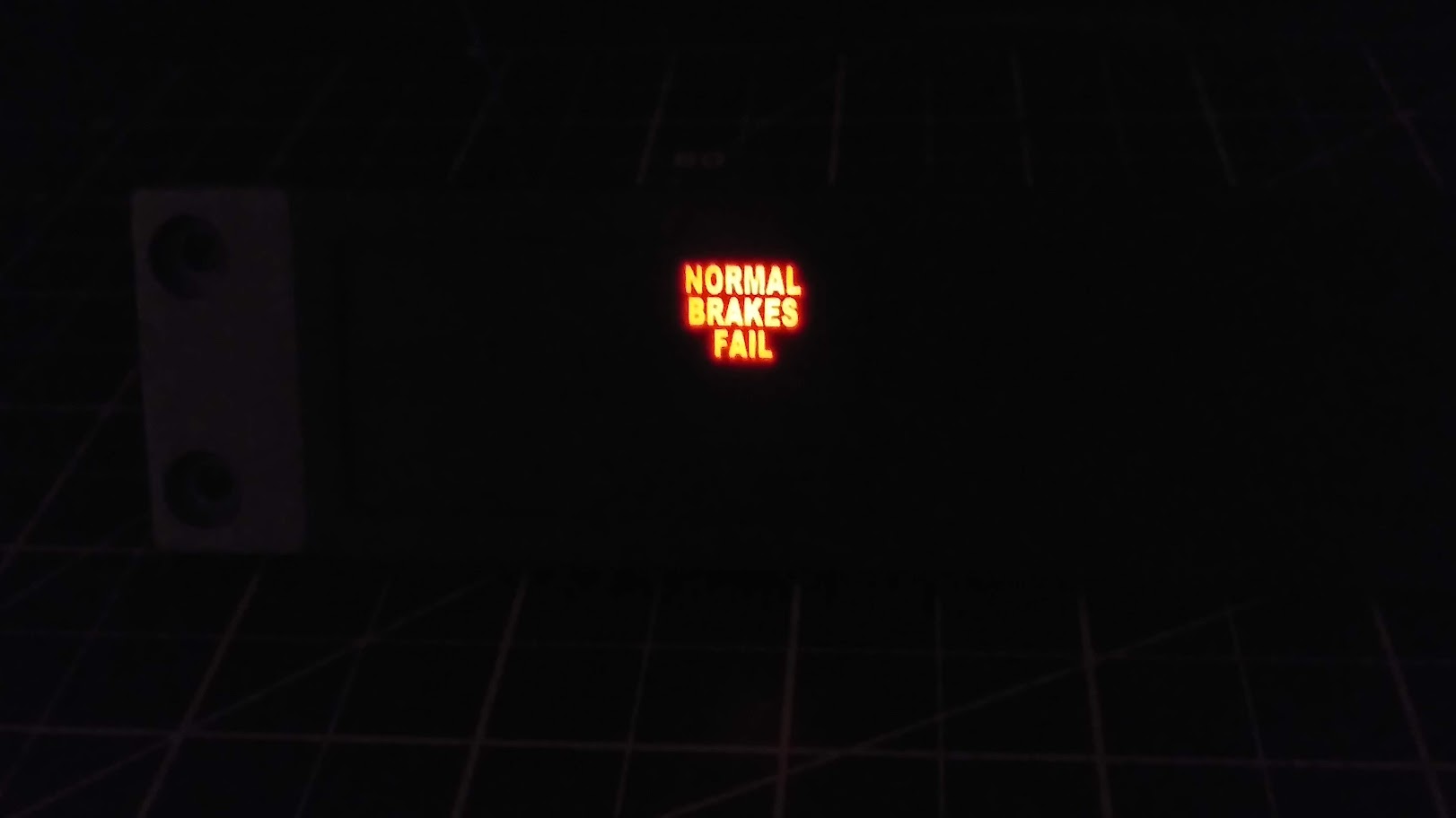
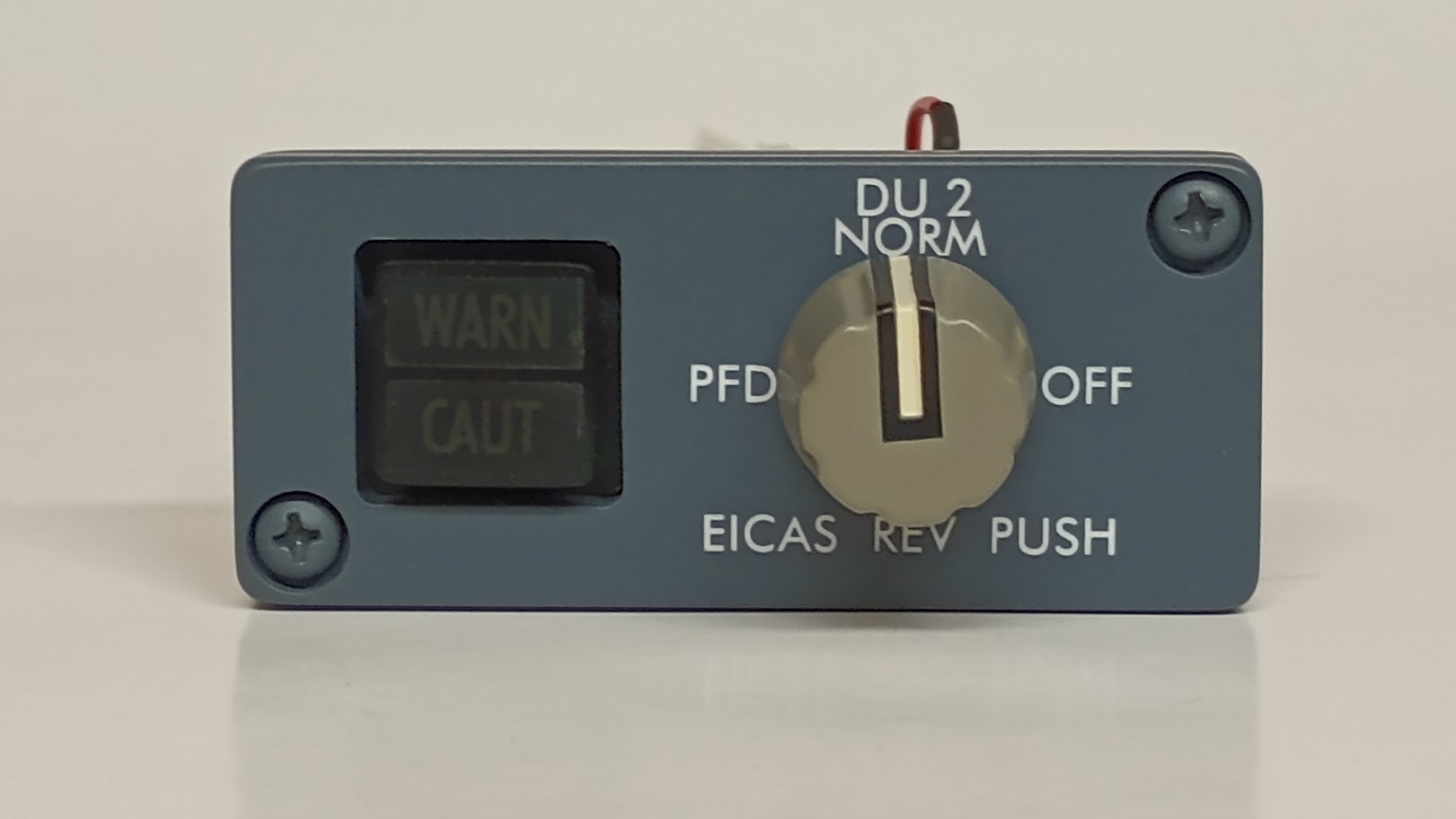
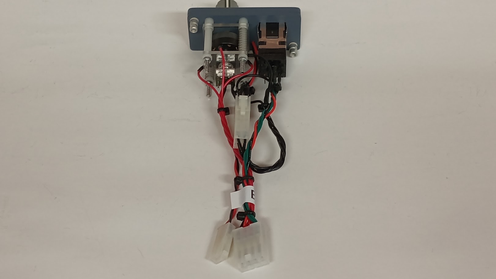
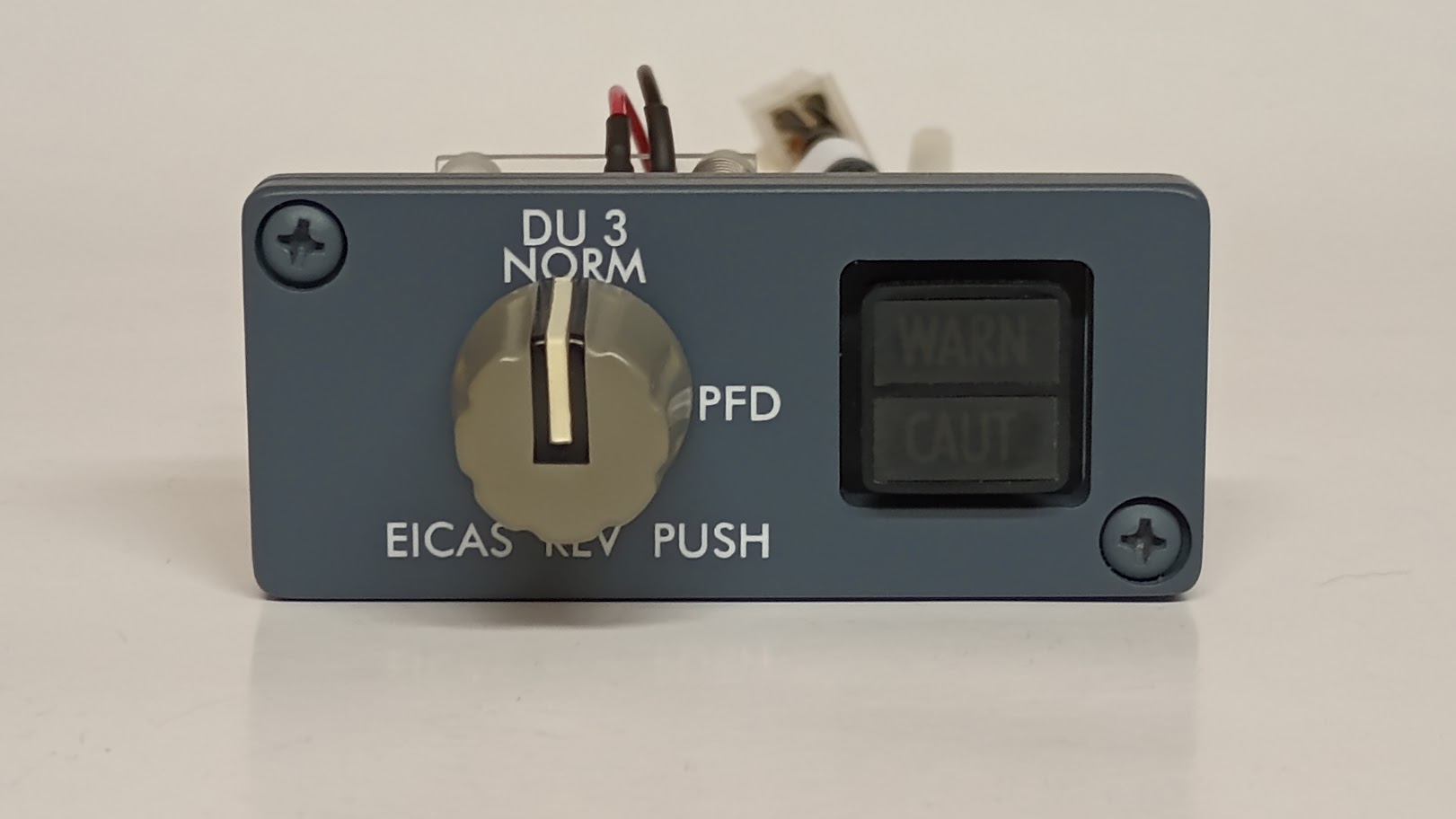
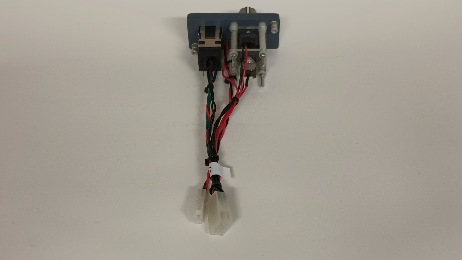
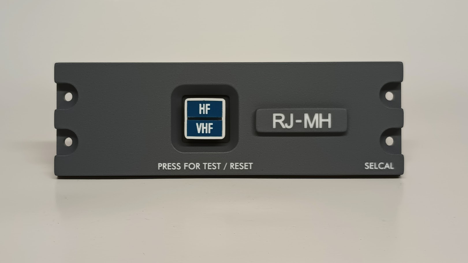
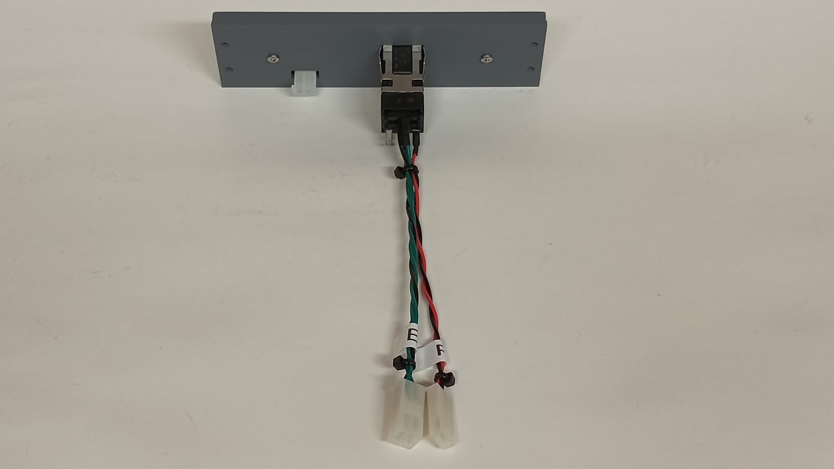
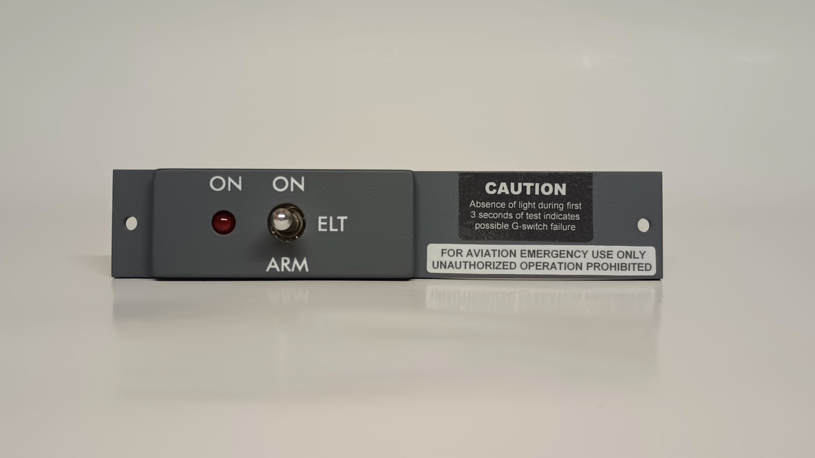
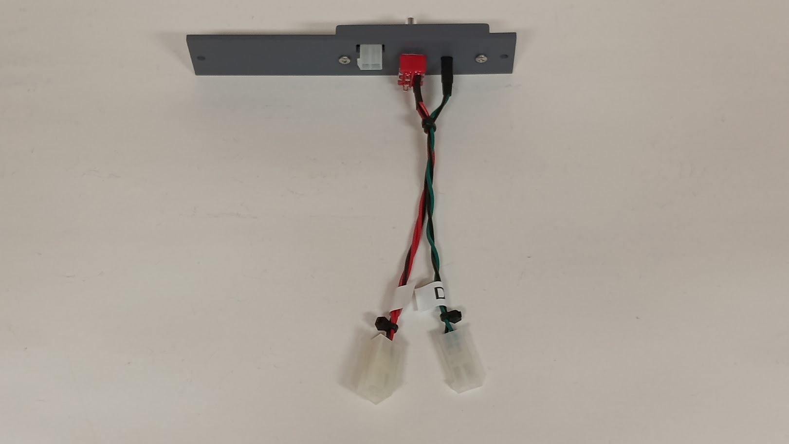
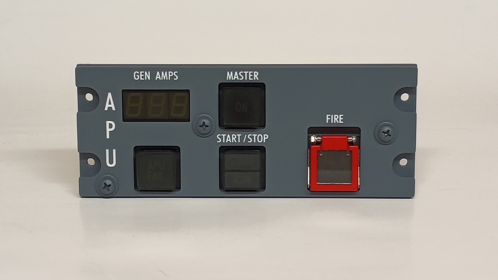
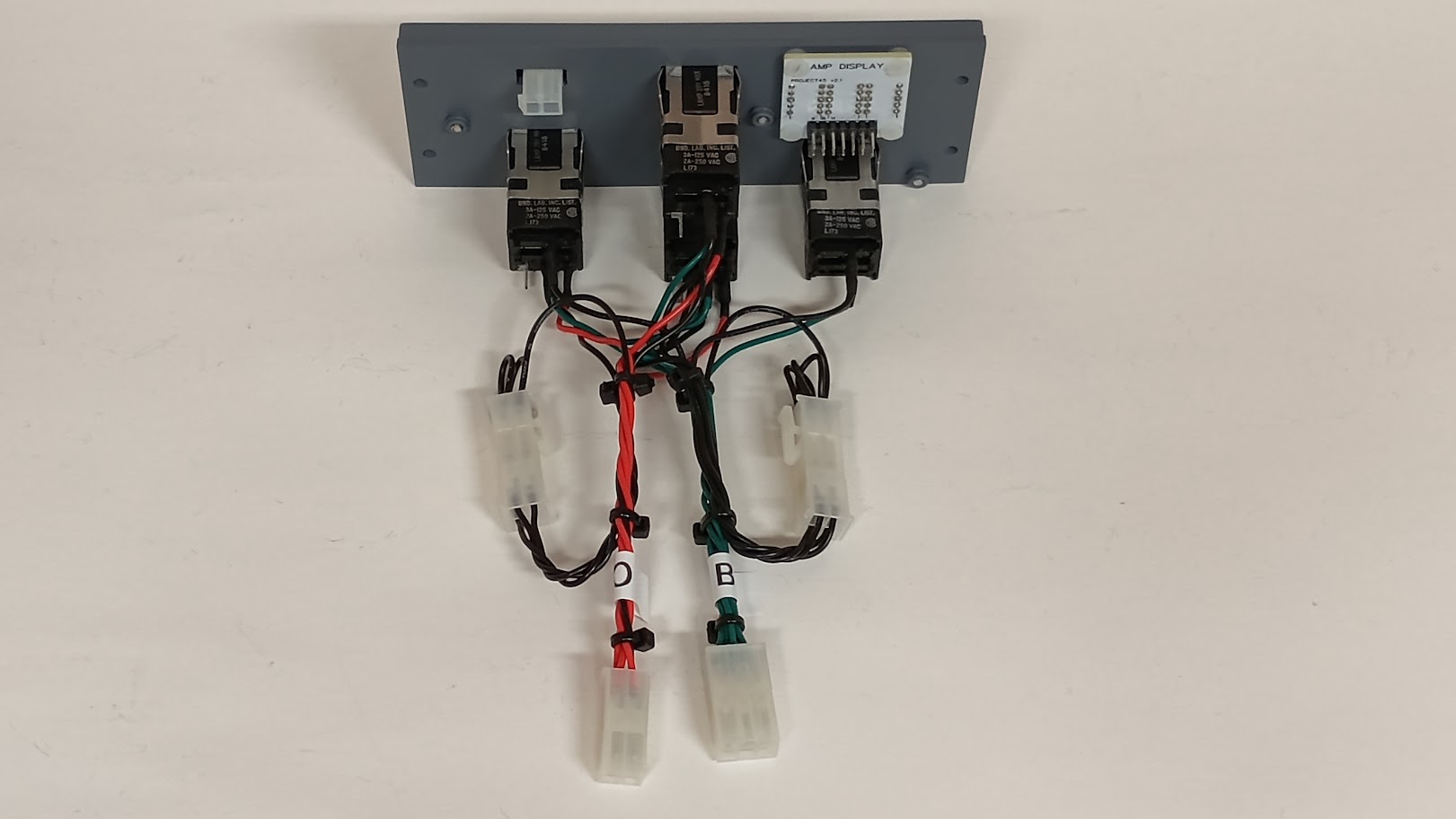
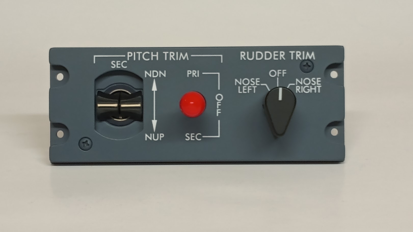
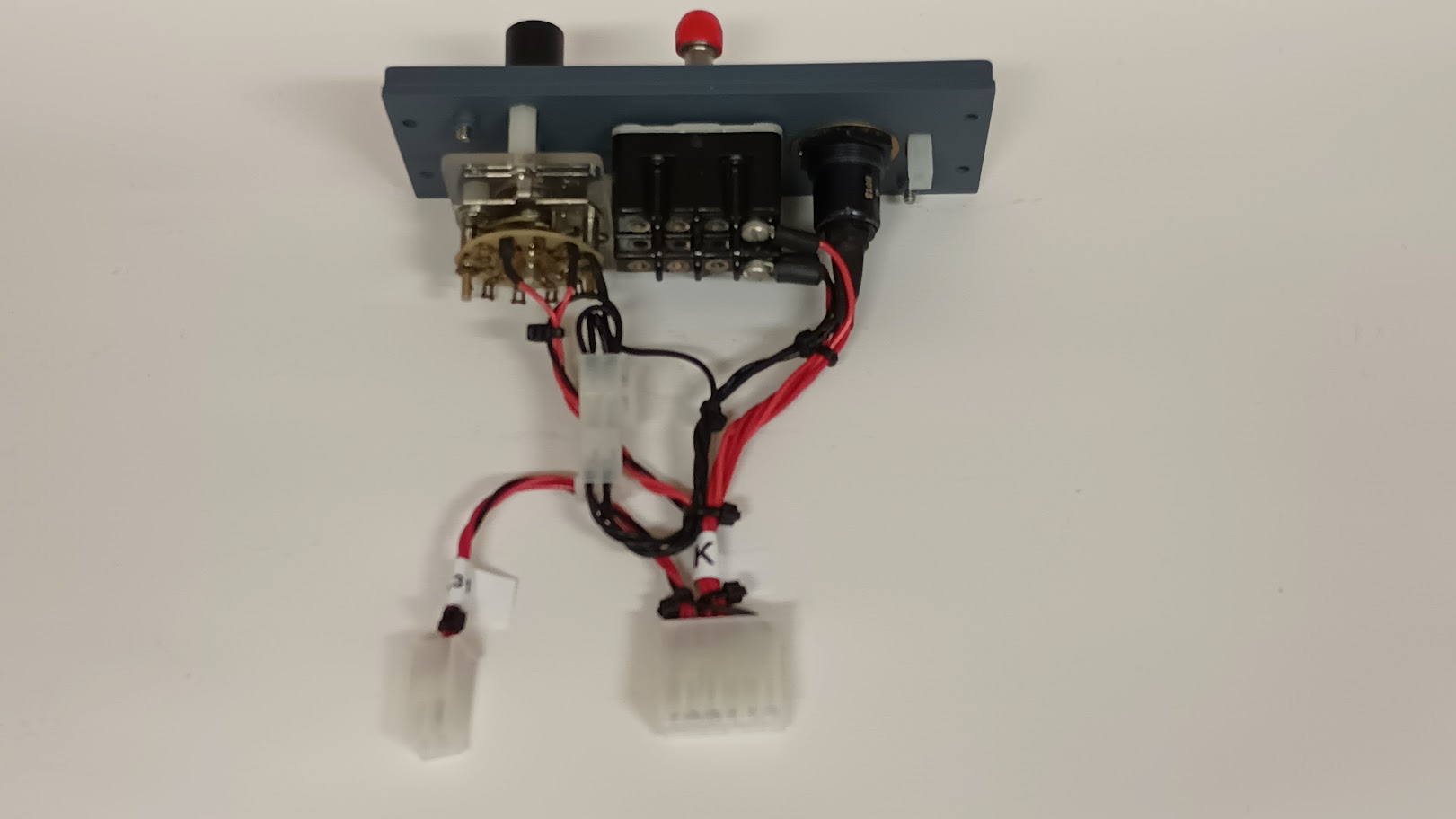
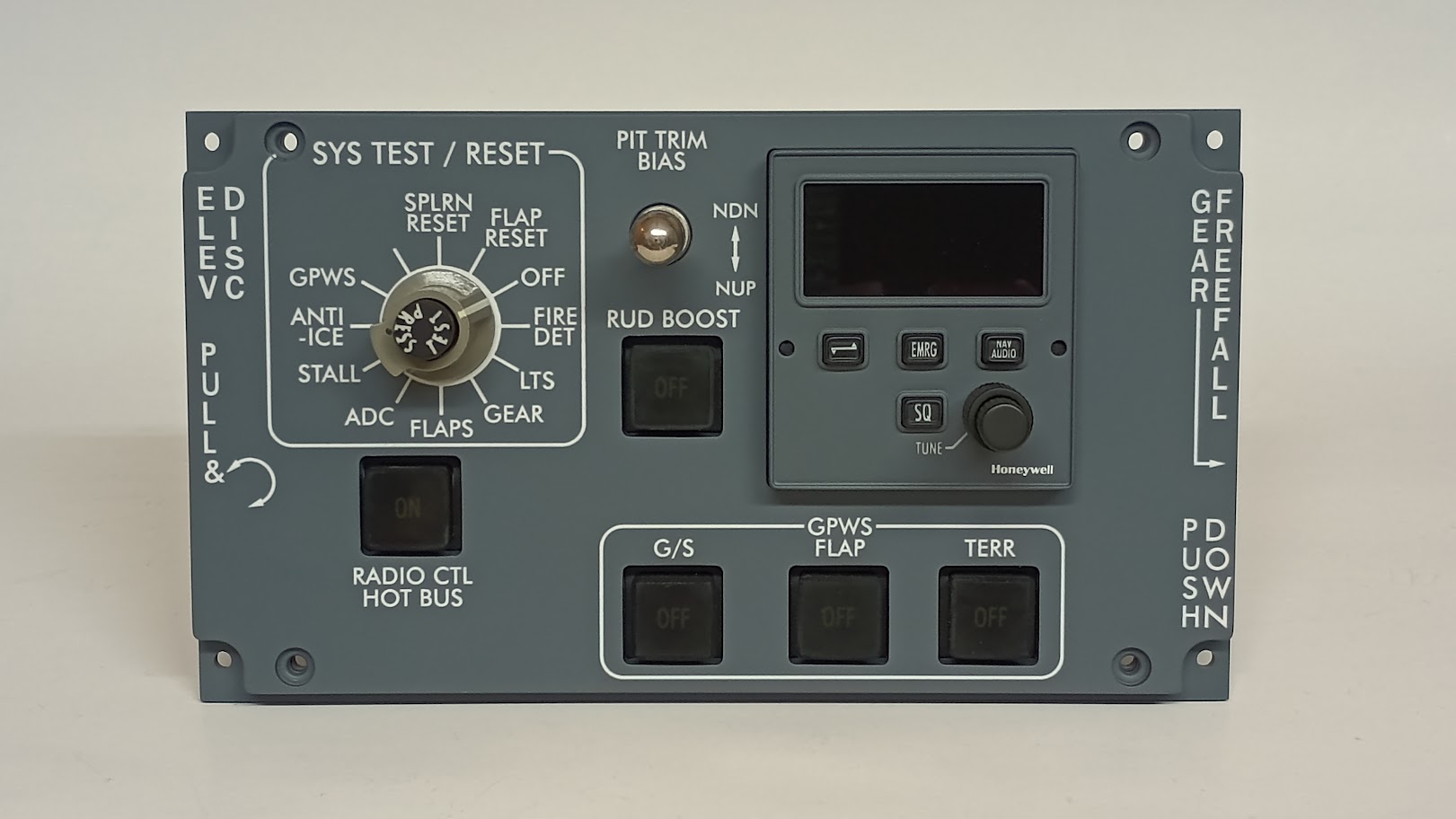
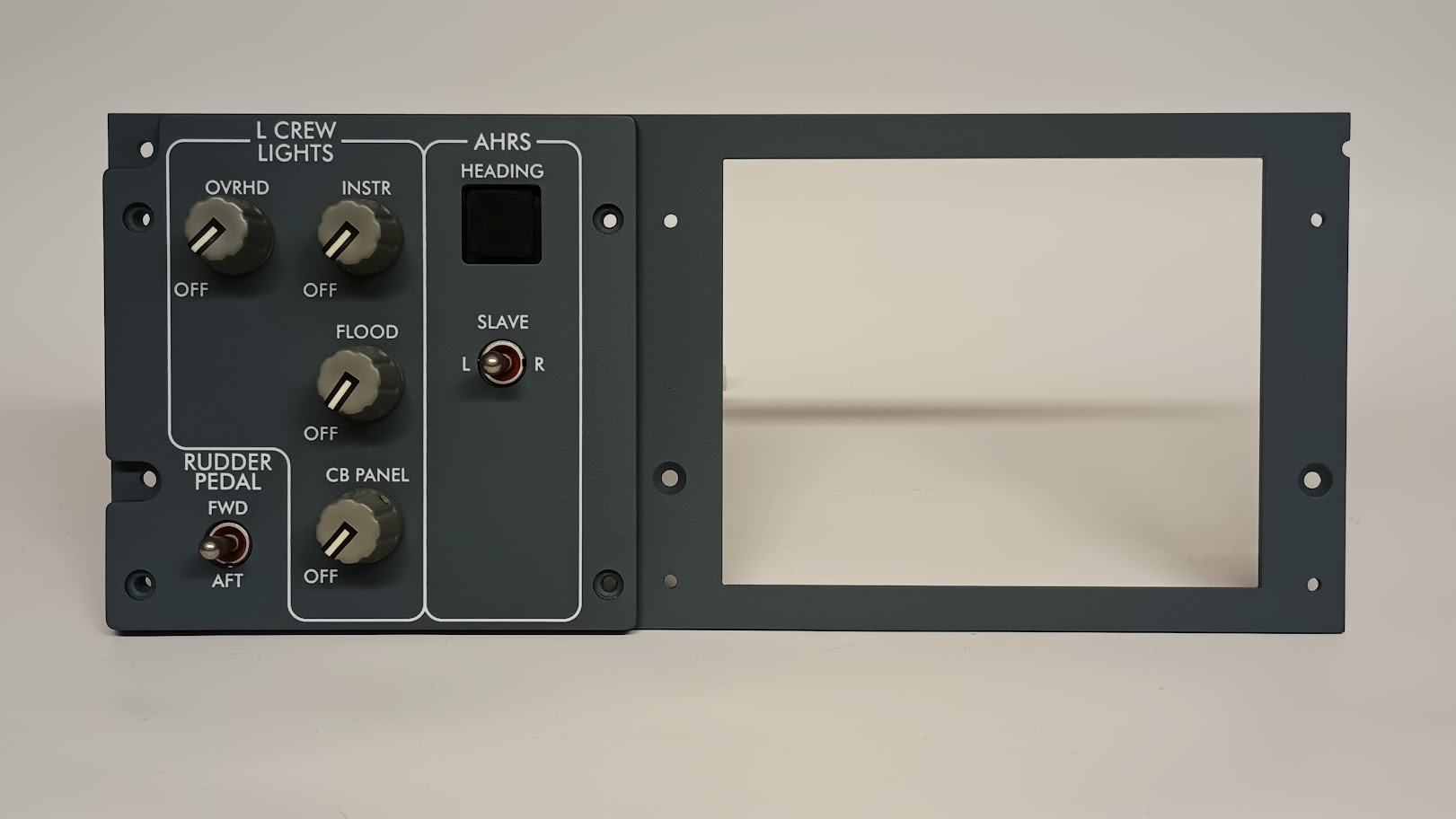
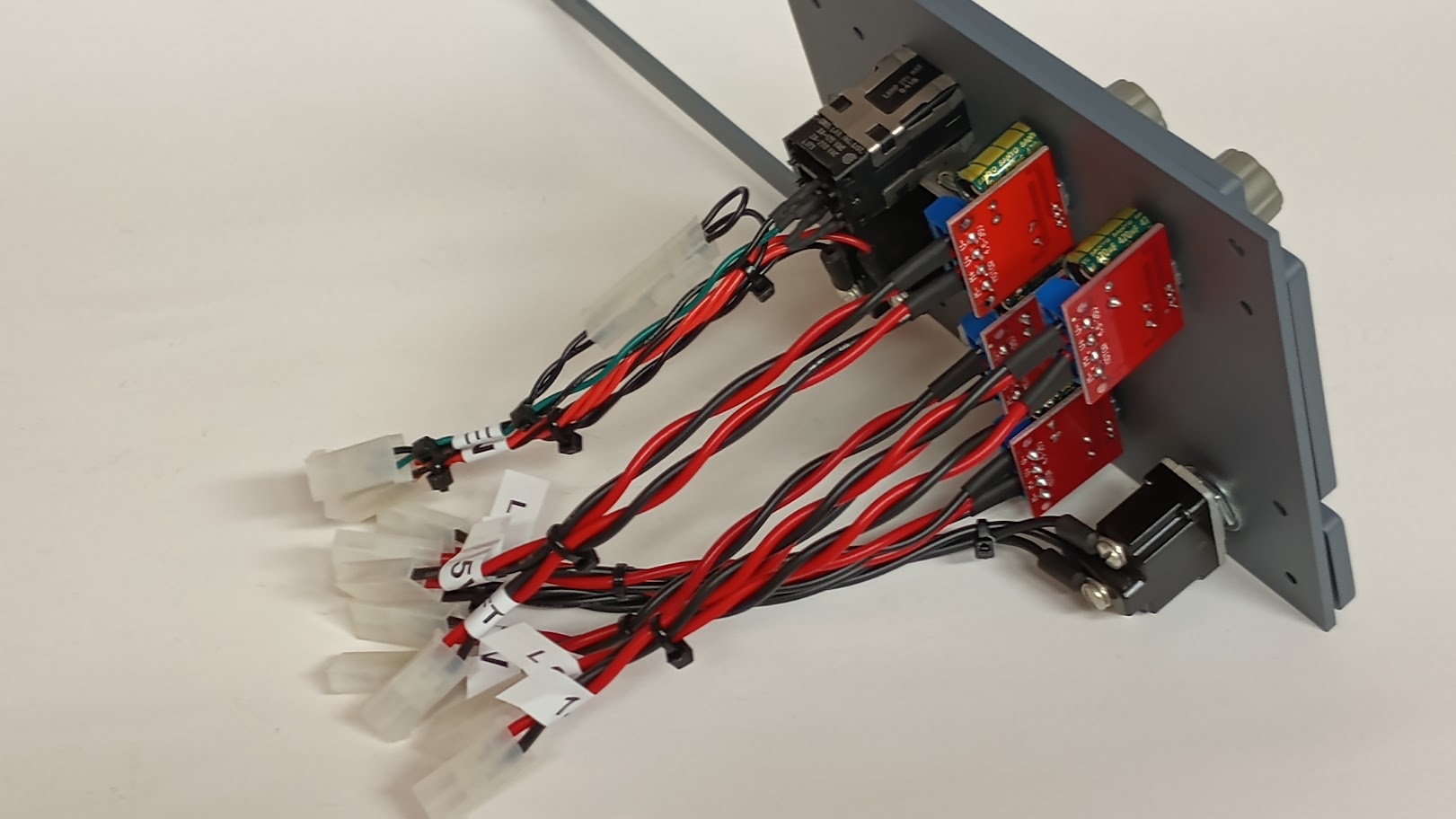
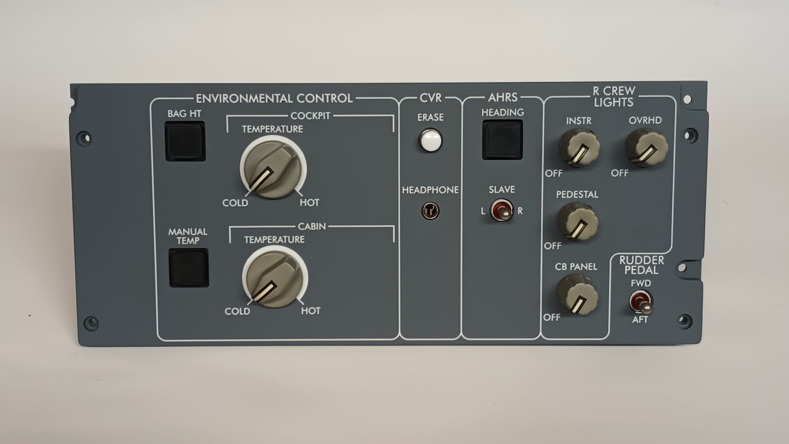
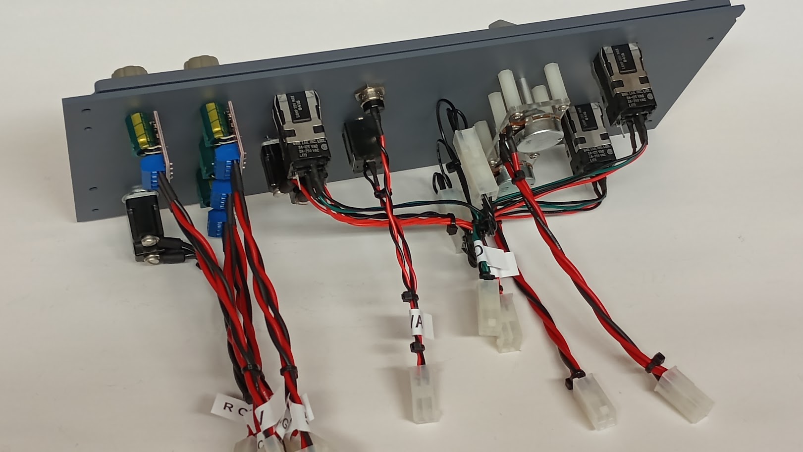
Another quick update. The past week I have been busy painting panels front and back. I am about 80% complete with this part of the process and will have all the panels painted in the next few days. The reason it takes so long to paint "a couple panels" is due to the masking of all the light bars that run across the top of the square switch holes. These light bars are designed to glow and shed a small amount of light on the switch body to make them easier to locate if they are not illuminated. (In normal flight conditions, all the switches in the flight deck are not illuminated) I am using Rust-Oleum Flat Gray Primer as a base and a finish coat on all front and backer panels. After the front panels dry, I checked them all to insure there is zero light bleed through the paint. In all cases so far, I have not had to add any paint. It is a fine balancing act.....too thin and light bleeds through. Too thick and the laser will not burn through all the paint! Here are a couple photos of several panels in various stages of the painting process. I am getting so close to finishing this panels that I can taste it.....probably just the paint in the air! Another quick update. The past week I have been busy painting panels front and back. I am about 80% complete with this part of the process and will have all the panels painted in the next few days. The reason it takes so long to paint "a couple panels" is due to the masking of all the light bars that run across the top of the square switch holes. These light bars are designed to glow and shed a small amount of light on the switch body to make them easier to locate if they are not illuminated. (In normal flight conditions, all the switches in the flight deck are not illuminated) I am using Rust-Oleum Flat Gray Primer as a base and a finish coat on all front and backer panels. After the front panels dry, I checked them all to insure there is zero light bleed through the paint. In all cases so far, I have not had to add any paint. It is a fine balancing act.....too thin and light bleeds through. Too thick and the laser will not burn through all the paint! Here are a couple photos of several panels in various stages of the painting process. I am getting so close to finishing this panels that I can taste it.....probably just the paint in the air! Quick update! All the panels are painted and are in the process of curing. For some reason, the last can of paint I used has left about six panels a little tacky even after several days. I can handle them but want to wait until they are completely dry before turning them over to the laser shop. The other issue I am working on is refining my artwork drawings. I am finding a few little things here and there but nothing terrible. However, the big thing that I am dealing with is when I import a dxf drawing into Coral Draw, the text shifts slightly and is a little larger than what I started with in the dxf drawing. To combat this, I am drawing "guide frames" around all the text artwork in the dxf drawing so that I know exactly where the text belongs in the cdr drawing. If it was just one or two panels this would not be a big deal but because I am going back and updating ALL my drawings, it is taking a little time. Probably the same amount of time as it takes to watch paint dry! If you are not into reading about watching paint dry, this might wake you up. Jason and I have been working hard at finalizing the Jet45 modules, particularly those that deal with the Advanced Avionics Suite. Just recently I have started converting the modules into pcb form and placed a couple test orders. A "couple" to a PCB manufacture is quantities around 25 by the way which is enough to get all of us started and then some! (Once we insure all is good with them) In the photo below, I have the DU2/REV1 Module, RMU2 Module and the APU Module with AMP display which is actually going to be part of the Jet45 Systems Software. Just to give you a sneak peak at what the final modules will look like, here they are with the Arduinos, plugs and stuff soldered in place! Not bad if you ask me! We are right on the front door steps of a truly plug and play solution for our Lear45! Again, a big thanks to Jason for envisioning this concept with such a complex project! Next step is to get these in Jason's hands early next week to do some further testing. There should be no difference between these and the previous clad versions with the exception that these PCBs look cool and take up less space. If all passes we will move forward with the rest of the Jet45 AAS modules and work to get a set in the hands of Mark S. to run them through the mill. Beats watching paint dry right? Quick update! All the panels are painted and are in the process of curing. For some reason, the last can of paint I used has left about six panels a little tacky even after several days. I can handle them but want to wait until they are completely dry before turning them over to the laser shop. The other issue I am working on is refining my artwork drawings. I am finding a few little things here and there but nothing terrible. However, the big thing that I am dealing with is when I import a dxf drawing into Coral Draw, the text shifts slightly and is a little larger than what I started with in the dxf drawing. To combat this, I am drawing "guide frames" around all the text artwork in the dxf drawing so that I know exactly where the text belongs in the cdr drawing. If it was just one or two panels this would not be a big deal but because I am going back and updating ALL my drawings, it is taking a little time. Probably the same amount of time as it takes to watch paint dry! If you are not into reading about watching paint dry, this might wake you up. Jason and I have been working hard at finalizing the Jet45 modules, particularly those that deal with the Advanced Avionics Suite. Just recently I have started converting the modules into pcb form and placed a couple test orders. A "couple" to a PCB manufacture is quantities around 25 by the way which is enough to get all of us started and then some! (Once we insure all is good with them) In the photo below, I have the DU2/REV1 Module, RMU2 Module and the APU Module with AMP display which is actually going to be part of the Jet45 Systems Software. Just to give you a sneak peak at what the final modules will look like, here they are with the Arduinos, plugs and stuff soldered in place! Not bad if you ask me! We are right on the front door steps of a truly plug and play solution for our Lear45! Again, a big thanks to Jason for envisioning this concept with such a complex project! Next step is to get these in Jason's hands early next week to do some further testing. There should be no difference between these and the previous clad versions with the exception that these PCBs look cool and take up less space. If all passes we will move forward with the rest of the Jet45 AAS modules and work to get a set in the hands of Mark S. to run them through the mill. Beats watching paint dry right? Finally, all the backlit panels are complete and most have been sent on their way to their new owners! However, I learned a couple lessons during the laser engraving process that I will share with everyone. First, we were forced to switch to a new paint, Rust-Oleum Flat Gray Primer which works and looks great. But it does require to be clear coated which I was not initially aware of. The clear flat takes any sheen out of the flat gray and strengthens the finish. It also helps hide any imperfections. It only takes a quick hit of clear to do the job. Don't saturate the panels with the clear flat or it could cause the paint under to bubble up. If applied properly, you are left with a perfect finish. Second, some of the larger front panels after they are milled out want to bow up. I had to make a clear blank panel to temporarily install in the front panels to pull them back to flat. This is important because the focus of the laser is critical. The blanks helped pull all the panels back to flat so that the lasers could engrave as close to it's focal point as possible. Once the panels are assembled for good and mounted properly, they are strong and flat. The last thing I learned is that I did not apply enough paint to the edges and had back lighting leaks. I was able to fix this by masking, taping, painting and clearing those edges. About 33% of my edges needed a little more paint. However, this might be the proper way to go about dealing with this issue. If you apply too much paint to the face of the panels, the lasers will not engrave through the paint. In other words, I was very careful to make sure I applied the exact thickness of paint to all the panels. And that amount is just enough to block the brightest light from a flash light. Our panels will never burn that bright so that was a great way to test. As it turned out, all the panels survived the laser engraving process and none in my opinion get a grade less than an A-, usually if you are working with 50 plus panels you end up with a couple that are B grade or C grade. Here are a couple photos of the panels: Pressurization Panel lit up! Left Crew, Environmental and System Test Panels.... The back side of those panels....... Here is a list of all the most recent panels and their pricing: Left Crew Panel $185 Electrical Panel $225 Gear / Hyd Panel $225 Pressurization Panel $245 Environmental Panel $245 Engine Panel $245 APU Panel $165 These panels have been added to the HANGAR PRODUCTS page! Finally, all the backlit panels are complete and most have been sent on their way to their new owners! However, I learned a couple lessons during the laser engraving process that I will share with everyone. First, we were forced to switch to a new paint, Rust-Oleum Flat Gray Primer which works and looks great. But it does require to be clear coated which I was not initially aware of. The clear flat takes any sheen out of the flat gray and strengthens the finish. It also helps hide any imperfections. It only takes a quick hit of clear to do the job. Don't saturate the panels with the clear flat or it could cause the paint under to bubble up. If applied properly, you are left with a perfect finish. Second, some of the larger front panels after they are milled out want to bow up. I had to make a clear blank panel to temporarily install in the front panels to pull them back to flat. This is important because the focus of the laser is critical. The blanks helped pull all the panels back to flat so that the lasers could engrave as close to it's focal point as possible. Once the panels are assembled for good and mounted properly, they are strong and flat. The last thing I learned is that I did not apply enough paint to the edges and had back lighting leaks. I was able to fix this by masking, taping, painting and clearing those edges. About 33% of my edges needed a little more paint. However, this might be the proper way to go about dealing with this issue. If you apply too much paint to the face of the panels, the lasers will not engrave through the paint. In other words, I was very careful to make sure I applied the exact thickness of paint to all the panels. And that amount is just enough to block the brightest light from a flash light. Our panels will never burn that bright so that was a great way to test. As it turned out, all the panels survived the laser engraving process and none in my opinion get a grade less than an A-, usually if you are working with 50 plus panels you end up with a couple that are B grade or C grade. Here are a couple photos of the panels: Pressurization Panel lit up! Left Crew, Environmental and System Test Panels.... The back side of those panels....... Here is a list of all the most recent panels and their pricing: Left Crew Panel $185 Electrical Panel $225 Gear / Hyd Panel $225 Pressurization Panel $245 Environmental Panel $245 Engine Panel $245 APU Panel $165 These panels have been added to the HANGAR PRODUCTS page! One of the biggest parts of the v2.0 update is moving from 12 volt to 5 volt backlighting. In order to make this happen, we have to update the 12 volt PWM dimmer potentiometers with new 5-35 volt PWM dimmer pots. (The PWM on the left is the old 12V and the PWM on the right is the new 5V) The new 5-35 volt PWMs work perfectly and are even equipped with a capacitor to help reduce noise! The only issue is that the new PWMs have a very short potentiometer shaft and are slightly under sized. The solution to this problem is simple but at the same time took a little time to find and fabricate the parts needed to address the issue. The photo below is a great illustration of what we get when we buy the 5 volt PWMs (left) , the solution to the short shaft issue (middle) and the final resolution to the problem (right). This photo shows the difference between the new and improved PWM shaft (left) and the old PWM shaft (right) Once the modification is complete, the final steps are slipping on the knobs and tightening them down with the set screws. There are two ways to go about getting a set of these Potentiometer Extension pieces. You can obtain them from the HANGAR45 PRODUCTS page or you can make them yourself if you have access to a CNC machine. The cost for a kit which is a set of eight is $45. If you are up to making the kit yourself, the first thing you will need to do is find some stainless steel tubing, .25" O.D. and .24" I.D with the side walls only being .005" thick. If you are thinking that this is super thin you would be thinking correctly! But surprisingly, it is strong and if made properly, the last thing that is going to fail is going to be the modified pot shafts. I tried a couple typical ways to cut the metal tubing but eventually settled into using a small cutting disk with my Drimel tool and a steady hand. The final length of these pieces needed to be exactly .625" long. My rough cuts with the disk were about .65" to .66" long. I then used a bench disk sander and a couple makeshift 90 degree braces to fine tune the pieces down to .625". The trick was to use tape on my finger to hold the pieces, keep them from spinning and to also insulate my finger from the friction heat. The final result is that all the stainless steel tubes are .625" long +/- .001" The small black "T" plugs are made with the CNC and those files are available upon request. They will be uploaded to the BUILDER RESOURCES page ASAP. These pieces are made of a hard but pliable Polly plastic. The photo below is a set of eight to make up a complete kit. These pieces are designed to be very tight and the tolerances are super close, so close that if cut with a worn bit, this will make a difference in the fit! Even if the fit is super tight, I recommend using a little gel to "seal the deal", bonding these pieces to the PWM shaft for good. On the subject of glue, be sure to use a glue gel that allows at least 30 seconds of set time. Either of these in the photo below work well. After pressing the "T" plug onto the PWM shaft, add a little gel at the joints. Wipe any extra away with a paper towel and then push the metal tube onto the shaft. Make sure to be careful to not push the tube too far down. You do not want the tube to contact the threads at the base of the encoder. The end result is that you will have a complete set of modified 5 volt PWM dimmer potentiometers ready to be installed onto your Left Crew and Environmental Panels! More panel related updates as they materialize! One of the biggest parts of the v2.0 update is moving from 12 volt to 5 volt backlighting. In order to make this happen, we have to update the 12 volt PWM dimmer potentiometers with new 5-35 volt PWM dimmer pots. (The PWM on the left is the old 12V and the PWM on the right is the new 5V) The new 5-35 volt PWMs work perfectly and are even equipped with a capacitor to help reduce noise! The only issue is that the new PWMs have a very short potentiometer shaft and are slightly under sized. The solution to this problem is simple but at the same time took a little time to find and fabricate the parts needed to address the issue. The photo below is a great illustration of what we get when we buy the 5 volt PWMs (left) , the solution to the short shaft issue (middle) and the final resolution to the problem (right). This photo shows the difference between the new and improved PWM shaft (left) and the old PWM shaft (right) Once the modification is complete, the final steps are slipping on the knobs and tightening them down with the set screws. There are two ways to go about getting a set of these Potentiometer Extension pieces. You can obtain them from the HANGAR45 PRODUCTS page or you can make them yourself if you have access to a CNC machine. The cost for a kit which is a set of eight is $45. If you are up to making the kit yourself, the first thing you will need to do is find some stainless steel tubing, .25" O.D. and .24" I.D with the side walls only being .005" thick. If you are thinking that this is super thin you would be thinking correctly! But surprisingly, it is strong and if made properly, the last thing that is going to fail is going to be the modified pot shafts. I tried a couple typical ways to cut the metal tubing but eventually settled into using a small cutting disk with my Drimel tool and a steady hand. The final length of these pieces needed to be exactly .625" long. My rough cuts with the disk were about .65" to .66" long. I then used a bench disk sander and a couple makeshift 90 degree braces to fine tune the pieces down to .625". The trick was to use tape on my finger to hold the pieces, keep them from spinning and to also insulate my finger from the friction heat. The final result is that all the stainless steel tubes are .625" long +/- .001" The small black "T" plugs are made with the CNC and those files are available upon request. They will be uploaded to the BUILDER RESOURCES page ASAP. These pieces are made of a hard but pliable Polly plastic. The photo below is a set of eight to make up a complete kit. These pieces are designed to be very tight and the tolerances are super close, so close that if cut with a worn bit, this will make a difference in the fit! Even if the fit is super tight, I recommend using a little gel to "seal the deal", bonding these pieces to the PWM shaft for good. On the subject of glue, be sure to use a glue gel that allows at least 30 seconds of set time. Either of these in the photo below work well. After pressing the "T" plug onto the PWM shaft, add a little gel at the joints. Wipe any extra away with a paper towel and then push the metal tube onto the shaft. Make sure to be careful to not push the tube too far down. You do not want the tube to contact the threads at the base of the encoder. The end result is that you will have a complete set of modified 5 volt PWM dimmer potentiometers ready to be installed onto your Left Crew and Environmental Panels! More panel related updates as they materialize! Now that the mother load of panels have been completed and behind me, I have a little time to take on a couple of the smaller and less important panels. Two of those new v2.0 panels would be the ELT and the SELCAL panels. Here is a snap shot of a couple pieces. If you already have earlier versions of the SELCAL and ELT panels, no need to order. However, the ELT panel requires a minor rework to become v2.0 compliant. The move is from a hardware logic solution to a software logic solution which requires replacement of the 12v red LED with a 3.2v red LED. You will find the full update on the ELT panel HERE Currently the front panels are at the laser shop and they should be back in a week or so. This is a small but necessary piece of the big puzzle just about complete! Additionally, I have just broke ground on the new v2.0 CWP (Crew Warning Panel). I am actually excited to be working on these because this is my first go around with the CWPs. Eric Tomlin created the earlier version for us all. Getting a chance to build a panel a little differently than all the others is my idea of fun and a challenge! The new v2.0 CWP will only have minor changes compared to the earlier version. First, it will now include the SPARE annunciation. The SPARE's only function is that it will illuminate during a light test. The second change will be improved light spread and the reduction of hot spots. One of the ways this will be achieved is that the light chambers behind the lens will be much deeper and protrude back into the MIP. This is only possible because of the new center monitor solution we are moving to consist of two 9" LCD screens, one for the standby gauges and one for the RMUs. This solution will leave a horizontal pocket in the space where the CWP will be, making it possible to have a deeper light chamber! Not much to see so far but several CWP lenses. They are cut, painted and laser engraved! This is the easy part of the CWP. What does this mean for you guys who already have a CWP? Well if you are happy with your early version CWP, there are no modifications needed to make it v2.0 compliant. Just follow the Jet45 AAS / Systems Module pinout document. More updates soon! Now that the mother load of panels have been completed and behind me, I have a little time to take on a couple of the smaller and less important panels. Two of those new v2.0 panels would be the ELT and the SELCAL panels. Here is a snap shot of a couple pieces. If you already have earlier versions of the SELCAL and ELT panels, no need to order. However, the ELT panel requires a minor rework to become v2.0 compliant. The move is from a hardware logic solution to a software logic solution which requires replacement of the 12v red LED with a 3.2v red LED. You will find the full update on the ELT panel HERE Currently the front panels are at the laser shop and they should be back in a week or so. This is a small but necessary piece of the big puzzle just about complete! Additionally, I have just broke ground on the new v2.0 CWP (Crew Warning Panel). I am actually excited to be working on these because this is my first go around with the CWPs. Eric Tomlin created the earlier version for us all. Getting a chance to build a panel a little differently than all the others is my idea of fun and a challenge! The new v2.0 CWP will only have minor changes compared to the earlier version. First, it will now include the SPARE annunciation. The SPARE's only function is that it will illuminate during a light test. The second change will be improved light spread and the reduction of hot spots. One of the ways this will be achieved is that the light chambers behind the lens will be much deeper and protrude back into the MIP. This is only possible because of the new center monitor solution we are moving to consist of two 9" LCD screens, one for the standby gauges and one for the RMUs. This solution will leave a horizontal pocket in the space where the CWP will be, making it possible to have a deeper light chamber! Not much to see so far but several CWP lenses. They are cut, painted and laser engraved! This is the easy part of the CWP. What does this mean for you guys who already have a CWP? Well if you are happy with your early version CWP, there are no modifications needed to make it v2.0 compliant. Just follow the Jet45 AAS / Systems Module pinout document. More updates soon! Hey guys, I completed a small run of v2.0 ELT and SELCAL panels a couple months ago and forgot to update this thread on that progress. I did update the ELT and the SELCAL threads and you can find more information on the finer details there. Here is a quick photo of the ELT panel. And here is the updated SELCAL panel. Next up.......the V2.0 Crew Warning Panel! I have already started them and now in full swing of getting them completed. The drawings are complete, the lenses are engraved and I have decided to go the route of using professional PCB for the components in place of the clad used in the version Eric made. As I mentioned above in the previous post, this V2.0 CWP is going to be designed to work with two dedicated LCD screens in place of the single LCD in portrait mode. One 9" LCD screen above for the standby gauges and one 9" LCD screen below for the RMUs. This will allow a free pocket of space behind the MIP to design and build the CWP! A question for you all, who needs the new V2.0 CWP? I have a short list of who is getting the new V2.0 CWP, but if you also want the new updated CWP, please contact me so that I can make sure I make enough and you get on the list. The price per unit will be $175, the same as what Eric first sold his version for over ten years ago. I expect to have them complete in three weeks! Hey guys, I completed a small run of v2.0 ELT and SELCAL panels a couple months ago and forgot to update this thread on that progress. I did update the ELT and the SELCAL threads and you can find more information on the finer details there. Here is a quick photo of the ELT panel. And here is the updated SELCAL panel. Next up.......the V2.0 Crew Warning Panel! I have already started them and now in full swing of getting them completed. The drawings are complete, the lenses are engraved and I have decided to go the route of using professional PCB for the components in place of the clad used in the version Eric made. As I mentioned above in the previous post, this V2.0 CWP is going to be designed to work with two dedicated LCD screens in place of the single LCD in portrait mode. One 9" LCD screen above for the standby gauges and one 9" LCD screen below for the RMUs. This will allow a free pocket of space behind the MIP to design and build the CWP! A question for you all, who needs the new V2.0 CWP? I have a short list of who is getting the new V2.0 CWP, but if you also want the new updated CWP, please contact me so that I can make sure I make enough and you get on the list. The price per unit will be $175, the same as what Eric first sold his version for over ten years ago. I expect to have them complete in three weeks! Quick update on the CWP progress. This past week I spent most of my time making some adjustments to the tool paths of the main body of the CWP. Because this CWP design is able to fall behind the MIP, it gives me no excuse not to solve the "hot spot" issue. The answer to the problem was to create a light chamber that sets the LEDs back further from the rear side of the lens. I am working on a run of eight CWPs. The main body will be made of two pieces bonded together. The CWP Backer and the CWP Light Chamber. These pieces are not yet bonded together but you can see how it will look and the benefits gained with this design. Back side view: Front side view with a dummy lens sitting in place: Recycled photo of the engraved lenses. No reason to be handling the real thing during the design and build up phase! Sneak peek at the new CWP mounted to the MIP! What is still missing from the CWP is the CWP Front Panel and the CWP PCB. I will have those completed by the end of next week. Another update soon! Quick update on the CWP progress. This past week I spent most of my time making some adjustments to the tool paths of the main body of the CWP. Because this CWP design is able to fall behind the MIP, it gives me no excuse not to solve the "hot spot" issue. The answer to the problem was to create a light chamber that sets the LEDs back further from the rear side of the lens. I am working on a run of eight CWPs. The main body will be made of two pieces bonded together. The CWP Backer and the CWP Light Chamber. These pieces are not yet bonded together but you can see how it will look and the benefits gained with this design. Back side view: Front side view with a dummy lens sitting in place: Recycled photo of the engraved lenses. No reason to be handling the real thing during the design and build up phase! Sneak peek at the new CWP mounted to the MIP! What is still missing from the CWP is the CWP Front Panel and the CWP PCB. I will have those completed by the end of next week. Another update soon! Another quick update on the CWP progress! This past week I completed the front panel part of the CWP which is the black top cover that frames the lens. It turns out this was one of the more challenging pieces I have cut because of the amount of material required to be removed. The milling time was as high as 90 minutes per piece but that could be reduced to under 60 minutes with some adjustments in the tool paths and speed. Tolerances were super tight from the 2-56 brass insert side walls to the front frame only being .0313" thick. This requires the CNC spoil board to be perfectly flat for starters. The CNC does the majority of the cutting but each piece has to be hand sanded in order to get the front pieces to fit onto the back piece. In this photo you see the back side of the two pieces and how tight the tolerances are. Several places on the CWP are very thin and could easily be broken during the manufacturing processes. But so far, (fingers crossed) nothing has broken and once the CWP is properly mounted to the MIP, it will be safe from breaking. Another test fit of the CWP on the v2.0 MIP now with the front panel and lens in place. Looking good! Here is a photo of all the major parts of the CWP. The CWP PCB arrived the other day as well. That turned out perfect! I had to split the plugs in two in order for the pins not interfering with the light chamber frame. This photo shows how the plugs were divided but are still considered a single plug. Speaking of the light chamber, I am in the process of painting the inside walls of the light chamber to keep the light from bleeding from one pocket into the others. What I am doing is spray painting and sanding several times. This is what two coats of flat black looks like with some sanding. Next I will hit them with flat white and then bond the light chambers to the back side of the CWP backer. As I have mentioned a couple times, this CWP is designed to flow behind the MIP. This is only possible due to the new way we are approaching the center monitor(s) issue. This photo clearly show how much of the CWP will be behind the MIP, not including the wiring harnesses! Paper filters are added to the CWP to remove the hot spots. The paper I am using is thick but translucent. This smooths out the light from the LEDs making the lettering look more uniform, crisp and clean. Last but not least, here is a sneak peak at an early light test. It's always hard to take good photos of what I am seeing. The actual color of the lettering is a deep red where as the photo looks a little orange and too bright. The light bleed that you see is real but to be expected because the paint process is not yet complete. Next week I will finish up on the sanding and paint process. Then all that is left is final assembly. One more update on the CWP and another major piece of our puzzle will be in the books! Another quick update on the CWP progress! This past week I completed the front panel part of the CWP which is the black top cover that frames the lens. It turns out this was one of the more challenging pieces I have cut because of the amount of material required to be removed. The milling time was as high as 90 minutes per piece but that could be reduced to under 60 minutes with some adjustments in the tool paths and speed. Tolerances were super tight from the 2-56 brass insert side walls to the front frame only being .0313" thick. This requires the CNC spoil board to be perfectly flat for starters. The CNC does the majority of the cutting but each piece has to be hand sanded in order to get the front pieces to fit onto the back piece. In this photo you see the back side of the two pieces and how tight the tolerances are. Several places on the CWP are very thin and could easily be broken during the manufacturing processes. But so far, (fingers crossed) nothing has broken and once the CWP is properly mounted to the MIP, it will be safe from breaking. Another test fit of the CWP on the v2.0 MIP now with the front panel and lens in place. Looking good! Here is a photo of all the major parts of the CWP. The CWP PCB arrived the other day as well. That turned out perfect! I had to split the plugs in two in order for the pins not interfering with the light chamber frame. This photo shows how the plugs were divided but are still considered a single plug. Speaking of the light chamber, I am in the process of painting the inside walls of the light chamber to keep the light from bleeding from one pocket into the others. What I am doing is spray painting and sanding several times. This is what two coats of flat black looks like with some sanding. Next I will hit them with flat white and then bond the light chambers to the back side of the CWP backer. As I have mentioned a couple times, this CWP is designed to flow behind the MIP. This is only possible due to the new way we are approaching the center monitor(s) issue. This photo clearly show how much of the CWP will be behind the MIP, not including the wiring harnesses! Paper filters are added to the CWP to remove the hot spots. The paper I am using is thick but translucent. This smooths out the light from the LEDs making the lettering look more uniform, crisp and clean. Last but not least, here is a sneak peak at an early light test. It's always hard to take good photos of what I am seeing. The actual color of the lettering is a deep red where as the photo looks a little orange and too bright. The light bleed that you see is real but to be expected because the paint process is not yet complete. Next week I will finish up on the sanding and paint process. Then all that is left is final assembly. One more update on the CWP and another major piece of our puzzle will be in the books! Final CWP update! Yesterday I finished up the Crew Warning Panels and they all turned out grade "A" or better. I will show you the final results at the end of this post but first, I want to cover a couple things that I had to do to get to this result. First, lots and lots of sanding. I was only making eight CWPs but if I had to make more, I would go back in the CAM program and make some adjustments so the tolerances would not be so tight. Making the adjustments manually was not too bad, just time consuming. I even removed a little extra material so that after the painting process, the parts would still fit together. This photo below shows part of the paint process. What you are looking at are paint plugs sitting on top of the back side of the CWPs. The trick was to keep the light from leaking into next door light chambers. As you saw in the previous post, I painted the light chambers black a couple time and then painted them white. I have about four coats of paint on the inside pockets of the light chambers, so much that the paint plugs don't fit in the pockets which is why they are sitting upside down! The goal was to keep the gray finish coat out of the light pockets and this worked. What we end up with are light pockets that are painted white to help reflect light and the main body of the panel painted gray. Here is a photo of everything painted and ready for final assembly, the moment I have been working towards! The first step in the assembly process was to bond the CWP Backer with the Light Chamber. I used screws in the center to help insure that the two pieces don't come apart due to the potential stresses of the wiring harnesses hanging off the back. The screws had to be perfectly countersunk so that they don't interfere with the lens. The ends of the light chamber were glued to the backer. Great shot of the white light chamber pockets also! The lenses popped into the CWP Front fairly easily as long as there was not too much paint. Speaking of paint, there is no risk of light bleed through the CWP Front panel, so no need to double coat them especially on the inside. Once the lenses are in place, the translucent paper filter lays on top. The tricky part of the assembly was pressing the CWP Front onto the CWP Backer. Lucky for me, I added just the right amount of paint to each piece and there were no issues. They all fit tight, but not so tight that there was a risk of anything breaking. Back side view of front piece pressed onto backer. Notice the paper filter? The easy part of adding the PCB to the back with six screws. The only thing to watch out for here was that the PCB board was right side up. Here is the complete CWP mounted in the MIP. As you can see, no room for a single LCD screen in portrait mode! Front side view. In a well lit room, like this one, the legends can barely be seen. In a dimly lit room, they can't be seen. The goal is we don't want to be able to see the legends unless they are illuminated. All in all, I don't think it is possible to make them look any better when it comes to hiding the legend while not illuminated. One last family photo of all the CWPs together before they are sent off to every corner of the globe! I have tested each of them and everything works perfectly. No light bleed and the color is perfect, bright but not too bright and the color is smooth throughout the legends. Believe it or not, the hardest part about this build was trying to take a photo that depicts exactly what my eye is seeing. This photo is the best that I could get but it is still not close to what I am seeing. To the naked eye, it is a deep smooth red, exactly the color and intensity you would want and expect. The photo makes it look orange, too bright and with a halo. That's not the case when observed in person. The Crew Warning Panel Discussion thread has been updated. Read about the operation and setup HERE More v2.0 Panel development coming soon! Final CWP update! Yesterday I finished up the Crew Warning Panels and they all turned out grade "A" or better. I will show you the final results at the end of this post but first, I want to cover a couple things that I had to do to get to this result. First, lots and lots of sanding. I was only making eight CWPs but if I had to make more, I would go back in the CAM program and make some adjustments so the tolerances would not be so tight. Making the adjustments manually was not too bad, just time consuming. I even removed a little extra material so that after the painting process, the parts would still fit together. This photo below shows part of the paint process. What you are looking at are paint plugs sitting on top of the back side of the CWPs. The trick was to keep the light from leaking into next door light chambers. As you saw in the previous post, I painted the light chambers black a couple time and then painted them white. I have about four coats of paint on the inside pockets of the light chambers, so much that the paint plugs don't fit in the pockets which is why they are sitting upside down! The goal was to keep the gray finish coat out of the light pockets and this worked. What we end up with are light pockets that are painted white to help reflect light and the main body of the panel painted gray. Here is a photo of everything painted and ready for final assembly, the moment I have been working towards! The first step in the assembly process was to bond the CWP Backer with the Light Chamber. I used screws in the center to help insure that the two pieces don't come apart due to the potential stresses of the wiring harnesses hanging off the back. The screws had to be perfectly countersunk so that they don't interfere with the lens. The ends of the light chamber were glued to the backer. Great shot of the white light chamber pockets also! The lenses popped into the CWP Front fairly easily as long as there was not too much paint. Speaking of paint, there is no risk of light bleed through the CWP Front panel, so no need to double coat them especially on the inside. Once the lenses are in place, the translucent paper filter lays on top. The tricky part of the assembly was pressing the CWP Front onto the CWP Backer. Lucky for me, I added just the right amount of paint to each piece and there were no issues. They all fit tight, but not so tight that there was a risk of anything breaking. Back side view of front piece pressed onto backer. Notice the paper filter? The easy part of adding the PCB to the back with six screws. The only thing to watch out for here was that the PCB board was right side up. Here is the complete CWP mounted in the MIP. As you can see, no room for a single LCD screen in portrait mode! Front side view. In a well lit room, like this one, the legends can barely be seen. In a dimly lit room, they can't be seen. The goal is we don't want to be able to see the legends unless they are illuminated. All in all, I don't think it is possible to make them look any better when it comes to hiding the legend while not illuminated. One last family photo of all the CWPs together before they are sent off to every corner of the globe! I have tested each of them and everything works perfectly. No light bleed and the color is perfect, bright but not too bright and the color is smooth throughout the legends. Believe it or not, the hardest part about this build was trying to take a photo that depicts exactly what my eye is seeing. This photo is the best that I could get but it is still not close to what I am seeing. To the naked eye, it is a deep smooth red, exactly the color and intensity you would want and expect. The photo makes it look orange, too bright and with a halo. That's not the case when observed in person. The Crew Warning Panel Discussion thread has been updated. Read about the operation and setup HERE More v2.0 Panel development coming soon! "Let the wiring begin!" A statement easier said than done. No matter if starting from complete scratch or reworking your panels from an earlier version, wiring up all the panels will take some time. There is nothing hard about the process, it's just time consuming. One thing we need to do no matter if wiring the panels for the first time or a rewire, is grouping the grounds in order to work with the new v2.0 Interface solution. Check out the latest post in the Wire Management and Solutions thread for additional information. Try to wire your panels as neat and secure as possible. Reducing the possibilities of Gremlins getting into your wiring will pay dividends ten times over in the long run. And it is easier to identify what is what while either building up your panels or trouble shooting issues if needed later on. A front and rear photo of each panel will be posted for illustration and to show all the hardware properly installed. All hardware part numbers have been listed in the Jet45 AAS Systems Modules document for easy access and identification! You can find the latest version of document HERE Starting with the smallest and easiest panels first, I am working up to the largest panels that will be posted later on in a separate post. Currently I am about a third of the way through this process! (Right click on any photo to enlarge) Left Reversion Panel: Right Reversion Panel: SELCAL Panel: ELT Panel: APU Panel: Pitch Trim Panel: System Test Panel: Left Crew Panel: Environmental Panel: As soon as the rest of the panels are populated and wired I will post them up. "Let the wiring begin!" A statement easier said than done. No matter if starting from complete scratch or reworking your panels from an earlier version, wiring up all the panels will take some time. There is nothing hard about the process, it's just time consuming. One thing we need to do no matter if wiring the panels for the first time or a rewire, is grouping the grounds in order to work with the new v2.0 Interface solution. Check out the latest post in the Wire Management and Solutions thread for additional information. Try to wire your panels as neat and secure as possible. Reducing the possibilities of Gremlins getting into your wiring will pay dividends ten times over in the long run. And it is easier to identify what is what while either building up your panels or trouble shooting issues if needed later on. A front and rear photo of each panel will be posted for illustration and to show all the hardware properly installed. All hardware part numbers have been listed in the Jet45 AAS Systems Modules document for easy access and identification! You can find the latest version of document HERE Starting with the smallest and easiest panels first, I am working up to the largest panels that will be posted later on in a separate post. Currently I am about a third of the way through this process! (Right click on any photo to enlarge) Left Reversion Panel: Right Reversion Panel: SELCAL Panel: ELT Panel: APU Panel: Pitch Trim Panel: System Test Panel: Left Crew Panel: Environmental Panel: As soon as the rest of the panels are populated and wired I will post them up. V2.0 Panel Progress by Project45
![]()
![]()
![]()
![]()
![]()
![]()
![]()
![]()
![]()
![]()

Forum NavigationV2.0 Panel Progress by Project45
![]() #21 · September 13, 2021, 3:35 pm
#21 · September 13, 2021, 3:35 pm![]() #22 · September 24, 2021, 7:41 am
#22 · September 24, 2021, 7:41 am![]() #23 · December 6, 2021, 8:58 am
#23 · December 6, 2021, 8:58 am![]() #24 · January 29, 2022, 11:59 pm
#24 · January 29, 2022, 11:59 pm![]() #25 · April 2, 2022, 12:18 am
#25 · April 2, 2022, 12:18 am![]() #26 · July 3, 2022, 4:50 pm
#26 · July 3, 2022, 4:50 pm![]() #27 · July 10, 2022, 1:30 pm
#27 · July 10, 2022, 1:30 pm![]() #28 · July 17, 2022, 12:51 am
#28 · July 17, 2022, 12:51 am![]() #29 · July 22, 2022, 2:40 pm
#29 · July 22, 2022, 2:40 pm![]() #30 · September 29, 2022, 10:20 am
#30 · September 29, 2022, 10:20 am
2017-10-10