


Hey guys, Over the past two months we have been super busy designing an all new fully functional RMU v2.0 which will include professionally made pcb, a professionally made one piece Silicone Keypad and a couple other cool improvements. This version will include the four buttons that were left behind in the first RMU version, the 1/2, SQ, TST and DME buttons. The planning/designing phase is now complete and we are gearing up to start production on the Radio Management Units (RMUs) v2.0! But before I start this new RMU thread, I needed to do a little forum house keeping. Previously, I had the Display Units and the v1.0 RMUs grouped together in one thread. Now you will find the v1.0 RMUs here followed by the v2.0 RMUs as I post updates on them. The Display Units now have their own dedicated thread. I expect to have the first batch of v2.0 RMUs completed no later than March 2024, depending on how many other side projects come into play. RMUs v1.0 The following archived information is in reference to the older v1.0 RMUs. (Original thread started on 05-05-15 by Ron Rollo) What to expect with the v1.0 RMUs. They will be designed to mount directly to the aluminum MIP with the LCD directly behind the MIP to provide the displays. This has always been a challenge because it limits us to design everything within the bezels which is about a half inch thick. No hardware will be allowed to protrude behind the aluminum MIP with the exception of the wires which will either be a flat ribbon cable or wires bound flat so that they will fit between the front of the LCD screen and the back side of the aluminum MIP. (Like some of us have now) The RMUs will work with Jet45 AAS because of the custom offsets within Jet45. They will be back lit, including the buttons to match Eric's panels as close as possible. The RMUs will be designed to work with the Pokeys56U interface cards and to take advantage of Mark L's utility that he design for the RMUs. The RMUs will have one common ground including the dual rotatory encoder. I decide to go with one common ground for all the hardware (dual encoder and push buttons) because when it comes right down to it, we are all going to have to use Mark's utility and the Pokeys56U interface cards. I spent many months trying to find an easy way to get the RMUs working without the utility and finally gave in to the idea. Thanks Mark for creating this software utility! I have completed the basic design of the PCB trace lines and have also decided to add in the little green light detector in the upper right corner. It will illuminate very softly making it look like it is working to detect the light level which would adjust the brightness of the back lighting. The RMUs will be backlit but this little green LED is just eye candy and will not have a function other than being dimly lit. Here is a sneak peak at the work in CAD so far: One of the biggest improvements over Vince's design is the fact that the dual encoder will be mounted on the same piece of double sided clad as everything else. This will give the encoder a solid base to sit on and will not wobble or work loose. I am hoping to have a working prototype of the PCB in about a week. UPDATE: As promised, I have some really neat photos of the first RMU prototype: There are 30 SMD LEDs mounted to the front side of the clad. Each LED has it's own resistor so in the rare case an LED goes out it will not effect the others. Also notice the green indicator LED in the top right corner. This is replicating the light sensor: I still have a ways to go but I can say that I am 99% complete with the design work. I will be offering the RMUs in kit form and in Plug and Play form. The RMU Kit will be $245 each and will include everything needed to complete one RMU. So make sure you let me know you want two. The RMU Plug and Play will be $395 each. They will be completely assembled with a couple 10 inch wiring harnesses coming out of the back side of them. If you want or need a wiring harness to the PoKeys card ad $45 per RMU. If interested, you can either email me or post in this thread. UPDATE: I advanced the RMUs a little further this week and I am very happy with the way that they are progressing. In this photo you can see that I have the wires soldered to the PCB clad and routed back through the backer panel. This wiring design is very simple for the end user. There are 20 red signal lines and one common ground. And then there are the two lines for the 12 volt power for the back lighting. It does not get easier than that: The back side of the RMU is just as simple. It is clean and the wires will flow easily out of the bottom between the aluminum MIP and the LCD screen. I am using 22 gauge wires. If you go with a kit, you might try 24 gauge if you want to go a little thinner: A closer look at the wires spilling out of the bottom of the RMU. Next week I should have the front of the RMU completed. The idea is that it will just snap onto what we have so far. (Posted by Randy Buchanan on 06-01-15) As always nice job. I wanted to be first on the list to order 2 complete RMU assemblies and I am sure there will be lots of orders for this bad boy. Thanks for doing the work for us! (Posted by Mark Speechley on 06-03-15) Ron, great job. Vince's RMU's have been problematic, especially one of them for me, so please put me down for one (1) plug and play RMU. I would use my RMU's more ....if they worked. (Posted by Ron Rollo on 06-03-15) Thanks guys, I guess I have no choice but to deliver a high quality RMU. I will say this, the RMU is a pretty complicated panel and it has a lot going on with it. That is the hard part of the design, trying to keep several aspects of the RMU in mind all at the same time. Lighting, fit, button movement, etc... Tomorrow I will be back at cutting parts and by Friday I should have some more photos. I got you down for one plug and play RMU Mark! UPDATE: I had a bit of a change of course with the RMU. I decided to build up what I had rather than to build the RMU front panel prototype. It took every bit of spare time over the past two weeks but they are done, the first batch anyway: Now I have no excuse to get to work on the RMU front panel. Keep your eyes open for the next update! UPDATE: Today I had an opportunity to design and make a template as a guide to alter the current aluminum MIPs. The current MIPs in the builder's hands are designed to accept Vince's RMUs. I have already updated the MIP drawings so that the MIP will be able to accept the Project45 RMUs as well as Vince's RMU design in the future. So for those of you who already have an aluminum MIP but are waiting on a set of Project45 RMUs, you will need to do this little modification to your MIP. This is the RMU template that your will get from me to make things a little easier for you. To take the guess work out of it: Take care in lining it up on the MIP. You might find that flipping it over fits the four mounting holes better. But all we really want to do is mark the lines where we want to open up the access hole for the wires and plugs more: I did mine in pencil. All the aluminum in the area of the marked lines must go in order for the wires and plugs from the Project45 RMUs to pass through the MIP: Vince's RMUs will still work with this modified MIP by the way. "More than one way to skin a cat?" I said that somewhere else not too long ago. Same thing applies here. I always try to find the easiest way with the tools that I have on hand. So first I removed as much material as possible with a metal drill bit along the inside perimeter of the lines: Then I broke out the bigger pieces using a set of cutting pliers. Be careful not to bend the MIP: Next I removed as much material as I could with a Dremel tool without getting too close to the lines: Last but not least, I finished off the edges with a metal file. Looks almost like it was cut with a water jet: This will insure that the wires and plugs to the RMUs will pass through the MIP with no issues! UPDATE: As promised, I have something to show everyone. This was my first attempt. The second one is even better. Next Tuesday I will have four solid days to get some serious work done on them. UPDATE: Sorry for the delayed update but we have a brand new member to the family. Baby Jett Maddox McCallum! (This makes me a step grandfather being that this little guy is the son of my wife's oldest son Christopher.) He arrived December 10th 2015 at 2242pm. In the future you will be seeing a lot of him here in the hangar flying the sim and getting involved in flight sim stuff. Anyway, last week my father and I got a lot of work done with the RMU faces. I am making six complete sets which most are accounted for so if you are interested and have not yet indicated that you want a set please do so. I like to try to knock several sets out at a time. Each piece takes one hour and fifteen minutes to cut on just the back side. The front side will take another hour! I did do a quick test to see how the buttons are going to work and they are going to be awesome! More photos next week. (Posted by Mark Speechley on 12-13-15) Congratulations on your grandson Jett. I imagine his nickname will be Lear? (Posted by Ron Rollo on 12-14-15) Thanks guys. I can't wait to show Jett all about the Lear sim and aviation in general. As for daughter boards, keeping it simple is key. And staying on task is the other key. I have wired up my RMU's three times now and everything that I have learned has made it into this design of the RMUs with "Simple" in mind. I also recommend using three Pokeys57U cards as I have pointed out in another thread. The idea of using a daughter board was in an effort to keep the cost down from purchasing two or three Pokeys cards. But for an additional $120 (the cost of two additional Pokeys cards) you can be headache free! The daughter board required that the one Pokeys card use the Matrix system where you would have wires sharing signals. I'm not sure how that would effect encoder set up. And, it would require another support program running in the background. So I have decided that the best way to move forward with the RMUs and DUs is to use three Pokeys56U or Pokeys57U cards and be done with it. And since I have gone this route (along with a few other fixes) I have had no problems at all. I just finished cutting the front panels to the RMUs. I have 16 which is 8 sets. I made a few extras for you stragglers out there. Each front panel took 2.5 hours to cut front and back. Mathematically that's 40 hours of cutting for just the front panel part of the RMU. I am surprised my CNC and router held up! Here is a photo of the stack of goodies: (Posted by Steve Cooke on 01-08-16) Nice. Is that 1/4" acrylic? I just purchased a CO2 laser engraver/cutter. The excitement is building as I wait for this thing. The lead time on production for it was a bit longer than originally anticipated but looking forward to doing all sorts of stuff with this thing. Ron, I'll be shooting you an email when I get home from work tonight on ordering the Alloy MIP/GS and covers. I'm just about ready for them. Paint on the pedestals has taken longer than anticipated due to all the rain. I've been shooting paint with my spray gun for a clean even coat and it has been turning out good. I'll have to post some pics of what I have tonight but it's just the simulated anti-corrosion green. I'm going to swing by hobby lobby to see if they have a can of gunship gray and attempt to get a paint match at Lowes this weekend. What kind of paint is used for gunship gray. Are we using flat, semi gloss, etc? Any particular brand over another? How about Latex, enamel or oil? (Posted by Shane Barnes on 01-08-16) Hey Steve, it's Model Master by Testor's. FS36118 Gunship Gray. It's a flat enamel. For your "matched" paint you can choose whatever you'd like but prototypically it's a flat finish throughout the cockpit. I sprayed a piece of four inch by 4 inch acrylic with the gunship gray and took the panel to Lowes for matching. Came out really good. Was far easier shooting the pedestal and MIP tower this way with a spray gun versus cans of gunship gray and cheaper. (Posted by Ron Rollo on 01-08-16) Hey guys thanks for the comments. I got a pretty good start on the buttons today. I should have all the parts cut out for the buttons by the end of my next set of days off. Steve, the front panel is .5" thick cast acrylic. And with that said, it actually measures in at around .45" Unfortunately, cast plastics vary in thickness due to the way it is created. But none the less, it is thick! But not as thick as the real RMU which makes it even more challenging to squeeze everything within such a small space. (Posted by Steve Cooke on 01-08-16) I've noticed cast acrylic varying in it's thickness. I would have never guessed the real RMU's to be so thick. I was guessing around .25". Nice work though, I hope mine come out that well. (Posted by Shane Barnes on 01-09-16) Ron and I were able to look at a real RMU. Ron didn't think I noticed but I could see the wheels spinning as he took mental notes of that RMU adding to the research he has done. Countless hours have been spent searching for photos, documents, real parts, anything we could get our hands on that would help in developing authentic looking parts for the project. All that work has paid off as attested by the many parts that Ron, Eric T., Mark, Tom, Eric G, and I am sure I am forgetting someone , has made available. Also the research has helped with all the information available to Lear builders. Looking back when I first started this project, I am amazed at how far we have come. (Posted by Ron Rollo on 01-09-16) Well said Shane. For a split second I thought about making the RMUs the same thickness as the real ones, but then I thought, "Why?" I can't recall what the real thickness is but it is about a 1/8th thicker than what I ended up going with. The first reason is the next thickest plastic stock is 3/4" thick which is more expensive compared to .5"ish. The amount of time it would take to mill down the thicker material was a factor. Last but not least, the mechanical aspects of the panel seems to work perfectly with the .5" thickness. The overall thickness is closer to .65" once you add in the backer panel. Just some food for thought. (Posted by Steve Cooke on 01-09-16) Okay. My research I was going off of was a 737 when I was originally looking into that. So all the panels are 1/2"? If so that will change up my design which will live me more room for everything. I was working on 1/4-3/8" thickness not counting the backer board. (Posted by Ron Rollo on 01-10-16) Hey Steve, your thinking was correct! The short answer is that most of the front panels in the Lear45 are .25" thick and the backers to those panels use .125" thick plastic. In this thread we are talking about the RMUs which are twice as thick as a typical panel in the Lear45. While we are at it, the other .5" thick panels or bezels belong to the Display Units, the CDU/FMS and the CDR. Everything else uses a .25" front and a .125" backer. (Keep in mind that the cast varies in thickness ans is usually a little thinner.) Sorry for any confusion and I hope this helps clear things up. In the meantime, this past week, my father, Ron Sr. and I have cut out over 500 pieces, mostly the button bodies and the button caps. However, the CNC finally died two days ago when the Z axis fried itself and the breakout board. I had a spare Z axis chip but the breakout board had to be ordered and will be here in a few days. The good news is I have enough parts cut out to complete everyone's current orders with the exception of the RMU encoder knobs. However, as long as I don't run into any more CNC surprises, they will be cut out within 10 days as well. Now for the tedious task of sanding, trimming, fitting, painting and prepping things for the laser shop! UPDATE: I have been working hard on sanding and filing all the button pieces. They are also glued together. Just a little more sanding and off to painting them. I would have a few photos of the progress but as you probably already know, my main computer is down and I can't get photos uploaded easily. Also still waiting to hear back from Probotix in reference to my two blown stepper driver chips. Right now my CNC machine is nothing more than a fancy computerized drill press! But as it is, I still have plenty of work to do without the CNC and it is not keeping me from moving forward. Not yet anyway. UPDATE: Quick update on the RMUs. The CNC is back up and running, although I think I may still have an issue with my Z axis sticking from time to time. (That's not good) I have completed most of the sanding and gluing of the buttons: I still need to cut out six more sets before I get to the painting and laser engraving part. With that said, I am currently working on getting things ready for the big day, April 16th 2016, Hangar Day! So although I am slowly working on the RMUs, they have been put on a side burner until after the big day. In case you are unaware of what I am talking about, we are planning to get as many Hangar45 members together here in Jax as we can for a day of fun, flying and friends. See post three HERE UPDATE: Hangar Day is behind us now and I have been busy working on the RMU buttons. I had six more sets to complete before painting and engraving. By the end of this day, I will have those six sets finally completed and we will be ready for the next steps in this process. (And by the end of this evening, my wife Michelle and I will be in Denver Colorado to meet with Randy Buchanan tomorrow. See you tomorrow Randy!) On a bit of a side note, Eric and I have been working on new techniques to make some of the panel and plastic work easier. And in one case, just possible. My hopes are that these new ideas will make the button making process faster and less labor intensive. It won't help with this batch of RMUs but will help with future sets and the DU buttons. Don't worry, the quality will be the same in both cases. (Posted by Shane Barnes on 05-11-16) Watching for updates to the RMU's! Nice seeing you take on this product and offer the Project45 version so it can be offered again after a long absence. I will be replacing the set I have with Project45 RMU's! (Posted by Ron Rollo on 05-18-16) I have finally got all the little buttons cut, glued, sanded and painted! Man, what an epic project. I felt like I was walking through quick sand: I have seventeen sets of buttons which will take care of eight sets of RMUs. This should be more than enough to take care of all of our members for a while anyway. Off to the laser shop next Tuesday. I have started on the dual rotary encoder knob design. These will be cut next Tuesday as well. UPDATE: For all you guys waiting forever for these RMUs, we are getting close. I got the buttons back from the laser shop a few days ago. Thanks to Lynn and her staff: This is the first test fit and I could not be happier. I am still using Vince's set of RMUs and plan to until they give me good reason to switch out. But man, these things are going to be nice and anyone who has a set on order, you will not be disappointed. At least I know a guy who makes RMUs when that day comes for myself! The money shot: These photos were taken with my smart phone and I am still trying to figure out the best way to take photos with it. But trust me, they look great! Now to get back to sanding, fiddling and painting. UPDATE: Finally guys, I am in the process of finishing up several sets and getting them out! Here are a few photos of the final product: If you happened to get a set of functional backers a few months ago and are waiting on the front panel and buttons, you will have to follow this simple tutorial. It should not take more than an hour to do both RMUs. The issue is that the tolerance to snap the front panel onto the clad is too tight and a small amount of material needs to be removed from the edges of the copper clad. So please take a look at this tutorial: First lets identify the problem. It may be hard to see in this photo but the copper clad is suppose to be inserted into the front panel: In this photo, you can see where it is not properly seated: There are two ways to help correct this. First, a flat sanding block. I am using 60 grit sand paper here: Second option, a Dremel tool. I ended up using both to achieve the desired fit: One small design error on my part is that I did not leave enough clearance in the front panel for this little solder joint that I am pointing at in this photo: To correct this, notch out a little section in this area of the inside front panel. I used the Dremel tool: And this is what it should look like once completed! The copper clad fits into the front panel which helps prevent light bleed from the panel. Very little light bleed slipping out: (Posted by Ron Rollo on 07-08-16) CONTINUATION: One other thing that you may have to do is shave out the inside of the button holes to remove some extra paint. I hit the front panels with four coats of paint to insure that there is no light bleeding through the paint: I used an Exacto knife to do this. Remove just enough until the buttons fit into the holes and are not impeded by the extra paint. Again, this tutorial only applies to a few of you guys and if you need or want to, you can always just send them back to me and I will take care of this for you. The function and feel of the switches are perfect, at least with the first set that I have complete. Shane is getting a set mailed out today and he will be able to compare this set to the set from Vince. UPDATE: The knobs are complete which means the RMUs are in the bag fellas! Some of you have already received them and others are still waiting. If you would like to get a set, contact me now while I am still in the RMU mood! Here are the completed photos of the RMUs now including the knobs: The back lighting of all the functions look near perfect! And what that means is that they look better than the real aircraft parts! In other words, they might look too good to fool you real world pilots! Enjoy the photos and the new functionality the the Project45 RMUs! (Posted by Shane Barnes on 08-11-16) I received the RMU's I purchased from Ron in the mail and you are really going to like them. The feel of the push switches is really nice and the encoder is solidly mounted as well and I really like the backlighting. Having a source for the RMU's is a great addition and as with all Ron's products, you will not be disappointed! I'm looking forward to adding them to my build next year when I plan on doing some updates to the sim and pulling the MIP out. (Posted by Mark Speechley on 08-11-16) Mine arrived and totally agree with Shane. So grateful that we have a great resource for parts in the Hangar group. Anyone holding off considering ordering then I'd jump on board if Ron still has spares. I have Vince's RMU's and have had endless trouble with them, I am so excited to finally have this aspect of the sim sorted. All coming together nicely now. Thanks Ron. (Posted by Jeff Peters on 08-11-16) I just ordered my set about 30 minutes ago. What has two thumbs pointing backwards and is very excited...THIS GUY (I'm pointing at myself) (Posted by Ron Rollo on 08-11-16) Thanks guys! I only wish I could have got them out to you all sooner. To date, they are the most complicated piece that I have put together so far. Along the way, I picked up several new skills and tricks with the designing and building of the RMUs. So hopefully the DUs that I have planned later this year won't take as long. Fingers crossed anyway. I do need to build some more RMUs, at least the PCB and backers. At least to have a couple sets standing by. I know there are at least three guys that will be asking for a set in the next few months or so. Thanks again and very happy to help fellow Lear45 builders! (Posted by Ron Rollo on 07-08-16) Today I tweaked the RMU drawings and started working on four more sets just to have on standby. There are no major design changes with this next RMU batch. I did move that one solder point in so we do not have to dremel the front panel. The other changes were simply better fit to reduce assembly time. A Hundredth of an inch here and there kind of stuff. (End of archived RMUs v1.0 ) Hey guys, Over the past two months we have been super busy designing an all new fully functional RMU v2.0 which will include professionally made pcb, a professionally made one piece Silicone Keypad and a couple other cool improvements. This version will include the four buttons that were left behind in the first RMU version, the 1/2, SQ, TST and DME buttons. The planning/designing phase is now complete and we are gearing up to start production on the Radio Management Units (RMUs) v2.0! But before I start this new RMU thread, I needed to do a little forum house keeping. Previously, I had the Display Units and the v1.0 RMUs grouped together in one thread. Now you will find the v1.0 RMUs here followed by the v2.0 RMUs as I post updates on them. The Display Units now have their own dedicated thread. I expect to have the first batch of v2.0 RMUs completed no later than March 2024, depending on how many other side projects come into play. RMUs v1.0 The following archived information is in reference to the older v1.0 RMUs. (Original thread started on 05-05-15 by Ron Rollo) What to expect with the v1.0 RMUs. They will be designed to mount directly to the aluminum MIP with the LCD directly behind the MIP to provide the displays. This has always been a challenge because it limits us to design everything within the bezels which is about a half inch thick. No hardware will be allowed to protrude behind the aluminum MIP with the exception of the wires which will either be a flat ribbon cable or wires bound flat so that they will fit between the front of the LCD screen and the back side of the aluminum MIP. (Like some of us have now) The RMUs will work with Jet45 AAS because of the custom offsets within Jet45. They will be back lit, including the buttons to match Eric's panels as close as possible. The RMUs will be designed to work with the Pokeys56U interface cards and to take advantage of Mark L's utility that he design for the RMUs. The RMUs will have one common ground including the dual rotatory encoder. I decide to go with one common ground for all the hardware (dual encoder and push buttons) because when it comes right down to it, we are all going to have to use Mark's utility and the Pokeys56U interface cards. I spent many months trying to find an easy way to get the RMUs working without the utility and finally gave in to the idea. Thanks Mark for creating this software utility! I have completed the basic design of the PCB trace lines and have also decided to add in the little green light detector in the upper right corner. It will illuminate very softly making it look like it is working to detect the light level which would adjust the brightness of the back lighting. The RMUs will be backlit but this little green LED is just eye candy and will not have a function other than being dimly lit. Here is a sneak peak at the work in CAD so far: One of the biggest improvements over Vince's design is the fact that the dual encoder will be mounted on the same piece of double sided clad as everything else. This will give the encoder a solid base to sit on and will not wobble or work loose. I am hoping to have a working prototype of the PCB in about a week. UPDATE: As promised, I have some really neat photos of the first RMU prototype: There are 30 SMD LEDs mounted to the front side of the clad. Each LED has it's own resistor so in the rare case an LED goes out it will not effect the others. Also notice the green indicator LED in the top right corner. This is replicating the light sensor: I still have a ways to go but I can say that I am 99% complete with the design work. I will be offering the RMUs in kit form and in Plug and Play form. The RMU Kit will be $245 each and will include everything needed to complete one RMU. So make sure you let me know you want two. The RMU Plug and Play will be $395 each. They will be completely assembled with a couple 10 inch wiring harnesses coming out of the back side of them. If you want or need a wiring harness to the PoKeys card ad $45 per RMU. If interested, you can either email me or post in this thread. UPDATE: I advanced the RMUs a little further this week and I am very happy with the way that they are progressing. In this photo you can see that I have the wires soldered to the PCB clad and routed back through the backer panel. This wiring design is very simple for the end user. There are 20 red signal lines and one common ground. And then there are the two lines for the 12 volt power for the back lighting. It does not get easier than that: The back side of the RMU is just as simple. It is clean and the wires will flow easily out of the bottom between the aluminum MIP and the LCD screen. I am using 22 gauge wires. If you go with a kit, you might try 24 gauge if you want to go a little thinner: A closer look at the wires spilling out of the bottom of the RMU. Next week I should have the front of the RMU completed. The idea is that it will just snap onto what we have so far. (Posted by Randy Buchanan on 06-01-15) As always nice job. I wanted to be first on the list to order 2 complete RMU assemblies and I am sure there will be lots of orders for this bad boy. Thanks for doing the work for us! (Posted by Mark Speechley on 06-03-15) Ron, great job. Vince's RMU's have been problematic, especially one of them for me, so please put me down for one (1) plug and play RMU. I would use my RMU's more ....if they worked. (Posted by Ron Rollo on 06-03-15) Thanks guys, I guess I have no choice but to deliver a high quality RMU. I will say this, the RMU is a pretty complicated panel and it has a lot going on with it. That is the hard part of the design, trying to keep several aspects of the RMU in mind all at the same time. Lighting, fit, button movement, etc... Tomorrow I will be back at cutting parts and by Friday I should have some more photos. I got you down for one plug and play RMU Mark! UPDATE: I had a bit of a change of course with the RMU. I decided to build up what I had rather than to build the RMU front panel prototype. It took every bit of spare time over the past two weeks but they are done, the first batch anyway: Now I have no excuse to get to work on the RMU front panel. Keep your eyes open for the next update! UPDATE: Today I had an opportunity to design and make a template as a guide to alter the current aluminum MIPs. The current MIPs in the builder's hands are designed to accept Vince's RMUs. I have already updated the MIP drawings so that the MIP will be able to accept the Project45 RMUs as well as Vince's RMU design in the future. So for those of you who already have an aluminum MIP but are waiting on a set of Project45 RMUs, you will need to do this little modification to your MIP. This is the RMU template that your will get from me to make things a little easier for you. To take the guess work out of it: Take care in lining it up on the MIP. You might find that flipping it over fits the four mounting holes better. But all we really want to do is mark the lines where we want to open up the access hole for the wires and plugs more: I did mine in pencil. All the aluminum in the area of the marked lines must go in order for the wires and plugs from the Project45 RMUs to pass through the MIP: Vince's RMUs will still work with this modified MIP by the way. "More than one way to skin a cat?" I said that somewhere else not too long ago. Same thing applies here. I always try to find the easiest way with the tools that I have on hand. So first I removed as much material as possible with a metal drill bit along the inside perimeter of the lines: Then I broke out the bigger pieces using a set of cutting pliers. Be careful not to bend the MIP: Next I removed as much material as I could with a Dremel tool without getting too close to the lines: Last but not least, I finished off the edges with a metal file. Looks almost like it was cut with a water jet: This will insure that the wires and plugs to the RMUs will pass through the MIP with no issues! UPDATE: As promised, I have something to show everyone. This was my first attempt. The second one is even better. Next Tuesday I will have four solid days to get some serious work done on them. UPDATE: Sorry for the delayed update but we have a brand new member to the family. Baby Jett Maddox McCallum! (This makes me a step grandfather being that this little guy is the son of my wife's oldest son Christopher.) He arrived December 10th 2015 at 2242pm. In the future you will be seeing a lot of him here in the hangar flying the sim and getting involved in flight sim stuff. Anyway, last week my father and I got a lot of work done with the RMU faces. I am making six complete sets which most are accounted for so if you are interested and have not yet indicated that you want a set please do so. I like to try to knock several sets out at a time. Each piece takes one hour and fifteen minutes to cut on just the back side. The front side will take another hour! I did do a quick test to see how the buttons are going to work and they are going to be awesome! More photos next week. (Posted by Mark Speechley on 12-13-15) Congratulations on your grandson Jett. I imagine his nickname will be Lear? (Posted by Ron Rollo on 12-14-15) Thanks guys. I can't wait to show Jett all about the Lear sim and aviation in general. As for daughter boards, keeping it simple is key. And staying on task is the other key. I have wired up my RMU's three times now and everything that I have learned has made it into this design of the RMUs with "Simple" in mind. I also recommend using three Pokeys57U cards as I have pointed out in another thread. The idea of using a daughter board was in an effort to keep the cost down from purchasing two or three Pokeys cards. But for an additional $120 (the cost of two additional Pokeys cards) you can be headache free! The daughter board required that the one Pokeys card use the Matrix system where you would have wires sharing signals. I'm not sure how that would effect encoder set up. And, it would require another support program running in the background. So I have decided that the best way to move forward with the RMUs and DUs is to use three Pokeys56U or Pokeys57U cards and be done with it. And since I have gone this route (along with a few other fixes) I have had no problems at all. I just finished cutting the front panels to the RMUs. I have 16 which is 8 sets. I made a few extras for you stragglers out there. Each front panel took 2.5 hours to cut front and back. Mathematically that's 40 hours of cutting for just the front panel part of the RMU. I am surprised my CNC and router held up! Here is a photo of the stack of goodies: (Posted by Steve Cooke on 01-08-16) Nice. Is that 1/4" acrylic? I just purchased a CO2 laser engraver/cutter. The excitement is building as I wait for this thing. The lead time on production for it was a bit longer than originally anticipated but looking forward to doing all sorts of stuff with this thing. Ron, I'll be shooting you an email when I get home from work tonight on ordering the Alloy MIP/GS and covers. I'm just about ready for them. Paint on the pedestals has taken longer than anticipated due to all the rain. I've been shooting paint with my spray gun for a clean even coat and it has been turning out good. I'll have to post some pics of what I have tonight but it's just the simulated anti-corrosion green. I'm going to swing by hobby lobby to see if they have a can of gunship gray and attempt to get a paint match at Lowes this weekend. What kind of paint is used for gunship gray. Are we using flat, semi gloss, etc? Any particular brand over another? How about Latex, enamel or oil? (Posted by Shane Barnes on 01-08-16) Hey Steve, it's Model Master by Testor's. FS36118 Gunship Gray. It's a flat enamel. For your "matched" paint you can choose whatever you'd like but prototypically it's a flat finish throughout the cockpit. I sprayed a piece of four inch by 4 inch acrylic with the gunship gray and took the panel to Lowes for matching. Came out really good. Was far easier shooting the pedestal and MIP tower this way with a spray gun versus cans of gunship gray and cheaper. (Posted by Ron Rollo on 01-08-16) Hey guys thanks for the comments. I got a pretty good start on the buttons today. I should have all the parts cut out for the buttons by the end of my next set of days off. Steve, the front panel is .5" thick cast acrylic. And with that said, it actually measures in at around .45" Unfortunately, cast plastics vary in thickness due to the way it is created. But none the less, it is thick! But not as thick as the real RMU which makes it even more challenging to squeeze everything within such a small space. (Posted by Steve Cooke on 01-08-16) I've noticed cast acrylic varying in it's thickness. I would have never guessed the real RMU's to be so thick. I was guessing around .25". Nice work though, I hope mine come out that well. (Posted by Shane Barnes on 01-09-16) Ron and I were able to look at a real RMU. Ron didn't think I noticed but I could see the wheels spinning as he took mental notes of that RMU adding to the research he has done. Countless hours have been spent searching for photos, documents, real parts, anything we could get our hands on that would help in developing authentic looking parts for the project. All that work has paid off as attested by the many parts that Ron, Eric T., Mark, Tom, Eric G, and I am sure I am forgetting someone , has made available. Also the research has helped with all the information available to Lear builders. Looking back when I first started this project, I am amazed at how far we have come. (Posted by Ron Rollo on 01-09-16) Well said Shane. For a split second I thought about making the RMUs the same thickness as the real ones, but then I thought, "Why?" I can't recall what the real thickness is but it is about a 1/8th thicker than what I ended up going with. The first reason is the next thickest plastic stock is 3/4" thick which is more expensive compared to .5"ish. The amount of time it would take to mill down the thicker material was a factor. Last but not least, the mechanical aspects of the panel seems to work perfectly with the .5" thickness. The overall thickness is closer to .65" once you add in the backer panel. Just some food for thought. (Posted by Steve Cooke on 01-09-16) Okay. My research I was going off of was a 737 when I was originally looking into that. So all the panels are 1/2"? If so that will change up my design which will live me more room for everything. I was working on 1/4-3/8" thickness not counting the backer board. (Posted by Ron Rollo on 01-10-16) Hey Steve, your thinking was correct! The short answer is that most of the front panels in the Lear45 are .25" thick and the backers to those panels use .125" thick plastic. In this thread we are talking about the RMUs which are twice as thick as a typical panel in the Lear45. While we are at it, the other .5" thick panels or bezels belong to the Display Units, the CDU/FMS and the CDR. Everything else uses a .25" front and a .125" backer. (Keep in mind that the cast varies in thickness ans is usually a little thinner.) Sorry for any confusion and I hope this helps clear things up. In the meantime, this past week, my father, Ron Sr. and I have cut out over 500 pieces, mostly the button bodies and the button caps. However, the CNC finally died two days ago when the Z axis fried itself and the breakout board. I had a spare Z axis chip but the breakout board had to be ordered and will be here in a few days. The good news is I have enough parts cut out to complete everyone's current orders with the exception of the RMU encoder knobs. However, as long as I don't run into any more CNC surprises, they will be cut out within 10 days as well. Now for the tedious task of sanding, trimming, fitting, painting and prepping things for the laser shop! UPDATE: I have been working hard on sanding and filing all the button pieces. They are also glued together. Just a little more sanding and off to painting them. I would have a few photos of the progress but as you probably already know, my main computer is down and I can't get photos uploaded easily. Also still waiting to hear back from Probotix in reference to my two blown stepper driver chips. Right now my CNC machine is nothing more than a fancy computerized drill press! But as it is, I still have plenty of work to do without the CNC and it is not keeping me from moving forward. Not yet anyway. UPDATE: Quick update on the RMUs. The CNC is back up and running, although I think I may still have an issue with my Z axis sticking from time to time. (That's not good) I have completed most of the sanding and gluing of the buttons: I still need to cut out six more sets before I get to the painting and laser engraving part. With that said, I am currently working on getting things ready for the big day, April 16th 2016, Hangar Day! So although I am slowly working on the RMUs, they have been put on a side burner until after the big day. In case you are unaware of what I am talking about, we are planning to get as many Hangar45 members together here in Jax as we can for a day of fun, flying and friends. See post three HERE UPDATE: Hangar Day is behind us now and I have been busy working on the RMU buttons. I had six more sets to complete before painting and engraving. By the end of this day, I will have those six sets finally completed and we will be ready for the next steps in this process. (And by the end of this evening, my wife Michelle and I will be in Denver Colorado to meet with Randy Buchanan tomorrow. See you tomorrow Randy!) On a bit of a side note, Eric and I have been working on new techniques to make some of the panel and plastic work easier. And in one case, just possible. My hopes are that these new ideas will make the button making process faster and less labor intensive. It won't help with this batch of RMUs but will help with future sets and the DU buttons. Don't worry, the quality will be the same in both cases. (Posted by Shane Barnes on 05-11-16) Watching for updates to the RMU's! Nice seeing you take on this product and offer the Project45 version so it can be offered again after a long absence. I will be replacing the set I have with Project45 RMU's! (Posted by Ron Rollo on 05-18-16) I have finally got all the little buttons cut, glued, sanded and painted! Man, what an epic project. I felt like I was walking through quick sand: I have seventeen sets of buttons which will take care of eight sets of RMUs. This should be more than enough to take care of all of our members for a while anyway. Off to the laser shop next Tuesday. I have started on the dual rotary encoder knob design. These will be cut next Tuesday as well. UPDATE: For all you guys waiting forever for these RMUs, we are getting close. I got the buttons back from the laser shop a few days ago. Thanks to Lynn and her staff: This is the first test fit and I could not be happier. I am still using Vince's set of RMUs and plan to until they give me good reason to switch out. But man, these things are going to be nice and anyone who has a set on order, you will not be disappointed. At least I know a guy who makes RMUs when that day comes for myself! The money shot: These photos were taken with my smart phone and I am still trying to figure out the best way to take photos with it. But trust me, they look great! Now to get back to sanding, fiddling and painting. UPDATE: Finally guys, I am in the process of finishing up several sets and getting them out! Here are a few photos of the final product: If you happened to get a set of functional backers a few months ago and are waiting on the front panel and buttons, you will have to follow this simple tutorial. It should not take more than an hour to do both RMUs. The issue is that the tolerance to snap the front panel onto the clad is too tight and a small amount of material needs to be removed from the edges of the copper clad. So please take a look at this tutorial: First lets identify the problem. It may be hard to see in this photo but the copper clad is suppose to be inserted into the front panel: In this photo, you can see where it is not properly seated: There are two ways to help correct this. First, a flat sanding block. I am using 60 grit sand paper here: Second option, a Dremel tool. I ended up using both to achieve the desired fit: One small design error on my part is that I did not leave enough clearance in the front panel for this little solder joint that I am pointing at in this photo: To correct this, notch out a little section in this area of the inside front panel. I used the Dremel tool: And this is what it should look like once completed! The copper clad fits into the front panel which helps prevent light bleed from the panel. Very little light bleed slipping out: (Posted by Ron Rollo on 07-08-16) CONTINUATION: One other thing that you may have to do is shave out the inside of the button holes to remove some extra paint. I hit the front panels with four coats of paint to insure that there is no light bleeding through the paint: I used an Exacto knife to do this. Remove just enough until the buttons fit into the holes and are not impeded by the extra paint. Again, this tutorial only applies to a few of you guys and if you need or want to, you can always just send them back to me and I will take care of this for you. The function and feel of the switches are perfect, at least with the first set that I have complete. Shane is getting a set mailed out today and he will be able to compare this set to the set from Vince. UPDATE: The knobs are complete which means the RMUs are in the bag fellas! Some of you have already received them and others are still waiting. If you would like to get a set, contact me now while I am still in the RMU mood! Here are the completed photos of the RMUs now including the knobs: The back lighting of all the functions look near perfect! And what that means is that they look better than the real aircraft parts! In other words, they might look too good to fool you real world pilots! Enjoy the photos and the new functionality the the Project45 RMUs! (Posted by Shane Barnes on 08-11-16) I received the RMU's I purchased from Ron in the mail and you are really going to like them. The feel of the push switches is really nice and the encoder is solidly mounted as well and I really like the backlighting. Having a source for the RMU's is a great addition and as with all Ron's products, you will not be disappointed! I'm looking forward to adding them to my build next year when I plan on doing some updates to the sim and pulling the MIP out. (Posted by Mark Speechley on 08-11-16) Mine arrived and totally agree with Shane. So grateful that we have a great resource for parts in the Hangar group. Anyone holding off considering ordering then I'd jump on board if Ron still has spares. I have Vince's RMU's and have had endless trouble with them, I am so excited to finally have this aspect of the sim sorted. All coming together nicely now. Thanks Ron. (Posted by Jeff Peters on 08-11-16) I just ordered my set about 30 minutes ago. What has two thumbs pointing backwards and is very excited...THIS GUY (I'm pointing at myself) (Posted by Ron Rollo on 08-11-16) Thanks guys! I only wish I could have got them out to you all sooner. To date, they are the most complicated piece that I have put together so far. Along the way, I picked up several new skills and tricks with the designing and building of the RMUs. So hopefully the DUs that I have planned later this year won't take as long. Fingers crossed anyway. I do need to build some more RMUs, at least the PCB and backers. At least to have a couple sets standing by. I know there are at least three guys that will be asking for a set in the next few months or so. Thanks again and very happy to help fellow Lear45 builders! (Posted by Ron Rollo on 07-08-16) Today I tweaked the RMU drawings and started working on four more sets just to have on standby. There are no major design changes with this next RMU batch. I did move that one solder point in so we do not have to dremel the front panel. The other changes were simply better fit to reduce assembly time. A Hundredth of an inch here and there kind of stuff. (End of archived RMUs v1.0 ) RMUs v2.0 This is the start of the new RMUs v2.0 postings! This is an all new fully functional RMU v2.0 which will include professionally made pcb, a professionally made one piece Silicone Keypad and a couple other cool improvements. This version will include the four buttons that were left behind in the first RMU version, the 1/2, SQ, TST and DME buttons. As I mentioned previously, we are finished with the design phase. I want to thank DonnyRay for sending me one of his authentic RMUs to insure the scale of this replica is spot on. (See photo below) For those with Eagle Eyes, you will note that this RMU does not have the inside beveled edges around the display screen. That's okay, I was able to still scale the replica RMU based on this example. Here is a snap shot of the RMU Master drawing. As always, the DXF, G-Code and any other related drawings will be released once everything has been checked and proven. One of the most time consuming aspects of the RMU and other more complex panels like the CDU and CDR are the buttons. It is possible to make them using a CNC machine and a laser engraver which is how they were made for the RMU v1.0 panels, but the chances of something going wrong during each step of the process is high. This is why we are moving to professionally made Silicone Keypads wherever possible. The tooling cost is high but the end results are perfection as long as everything is correct in the design process. This is another reason why it took several weeks to make sure everything was squared away in the drawings. Thanks to Will Sasse for his help in converting the 2D dxf button design drawings to 3D! A couple weeks ago I sent the files off to a manufacturing company and today the Silicone Keypads arrived! Take a look. They turned out perfect! As you can see, they are all built into one piece, they have the raised rim around the top edge and most importantly, they are backlightable. You might notice in the photo that I went ahead and had some CDR Silicone Keypads made since I had some dead space in the center of the RMU keypads. And did you know that the size of the CDR buttons are exactly the same size as the RMU LSK buttons? In a way, the RMU is being designed and built around the Silicone Keypad. In other words, if at this point fine tuning is required, it will be done in other aspects of the RMU, not the keypad. The Silicone Keypad is locked in due to the high tooling cost of the plug and molds. Another equally important part of the RMU design is the PCB. All hardware is mounted to this one board making it neat and easy to manage. Everything is already drawn out and ready to go, I just need to place the order. This next PCB order actually has several other unrelated pieces of PCB in it. All PCB is drawn and ready to go, but I like to take a few days to let it sit in case something that needs tweaking is discovered. Here is the RMU PCB front side drawings: Rear side: Once these arrive and are in hand, everything else can be made in house using a CNC machine and a laser engraver. The first batch will only be a total of ten units, which is five sets. All but one set has been accounted for. If you would like to get on this list, please let me know and I will adjust the build count as needed. I am aiming to keep the price around $295 per unit or $590 per set. In comparison, Vince's RMUs and my first version of the RMUs were around $750 per set and that was several years ago! The ability to reduce the price this much is due to using Silicone Keypads and the professionally made PCB, easier to assemble and a lower price! More updates on the RMUs soon. RMUs v2.0 This is the start of the new RMUs v2.0 postings! This is an all new fully functional RMU v2.0 which will include professionally made pcb, a professionally made one piece Silicone Keypad and a couple other cool improvements. This version will include the four buttons that were left behind in the first RMU version, the 1/2, SQ, TST and DME buttons. As I mentioned previously, we are finished with the design phase. I want to thank DonnyRay for sending me one of his authentic RMUs to insure the scale of this replica is spot on. (See photo below) For those with Eagle Eyes, you will note that this RMU does not have the inside beveled edges around the display screen. That's okay, I was able to still scale the replica RMU based on this example. Here is a snap shot of the RMU Master drawing. As always, the DXF, G-Code and any other related drawings will be released once everything has been checked and proven. One of the most time consuming aspects of the RMU and other more complex panels like the CDU and CDR are the buttons. It is possible to make them using a CNC machine and a laser engraver which is how they were made for the RMU v1.0 panels, but the chances of something going wrong during each step of the process is high. This is why we are moving to professionally made Silicone Keypads wherever possible. The tooling cost is high but the end results are perfection as long as everything is correct in the design process. This is another reason why it took several weeks to make sure everything was squared away in the drawings. Thanks to Will Sasse for his help in converting the 2D dxf button design drawings to 3D! A couple weeks ago I sent the files off to a manufacturing company and today the Silicone Keypads arrived! Take a look. They turned out perfect! As you can see, they are all built into one piece, they have the raised rim around the top edge and most importantly, they are backlightable. You might notice in the photo that I went ahead and had some CDR Silicone Keypads made since I had some dead space in the center of the RMU keypads. And did you know that the size of the CDR buttons are exactly the same size as the RMU LSK buttons? In a way, the RMU is being designed and built around the Silicone Keypad. In other words, if at this point fine tuning is required, it will be done in other aspects of the RMU, not the keypad. The Silicone Keypad is locked in due to the high tooling cost of the plug and molds. Another equally important part of the RMU design is the PCB. All hardware is mounted to this one board making it neat and easy to manage. Everything is already drawn out and ready to go, I just need to place the order. This next PCB order actually has several other unrelated pieces of PCB in it. All PCB is drawn and ready to go, but I like to take a few days to let it sit in case something that needs tweaking is discovered. Here is the RMU PCB front side drawings: Rear side: Once these arrive and are in hand, everything else can be made in house using a CNC machine and a laser engraver. The first batch will only be a total of ten units, which is five sets. All but one set has been accounted for. If you would like to get on this list, please let me know and I will adjust the build count as needed. I am aiming to keep the price around $295 per unit or $590 per set. In comparison, Vince's RMUs and my first version of the RMUs were around $750 per set and that was several years ago! The ability to reduce the price this much is due to using Silicone Keypads and the professionally made PCB, easier to assemble and a lower price! More updates on the RMUs soon. I really like the improvement to silicon keypads and the addition of the PCB's to all of these components. These look great! Looking forward to adding these new and improved features to L45-007 V2 build. I really like the improvement to silicon keypads and the addition of the PCB's to all of these components. These look great! Looking forward to adding these new and improved features to L45-007 V2 build. Hey guys, Happy New year! Hope everyone had a great holiday season. Here is to another productive sim building year. I think the work we have done in 2023 is setting us up perfectly for 2024! Over the holiday break I was busy soldering several panels, not just the RMUs. Recently I finished them all up, well almost. I am still waiting for a few hardware parts to arrive in order to complete them. Today the 12v translucent green LEDs came in that replicate the ambient light sensor in the top right corner of the RMUs so I was able to finish the RMU PCBs. I am working on a batch of ten. It's really cool seeing the artwork above in my previous post transform into real parts! Here is a close up of all the SMDs and hardware soldered to the PCB. Here is a photo of the backside of the RMU PCB. One of the tricks to making this design work is nearly everything on the backside of the PCB has to be flush. This means all through hole pins have to be snipped short so they sit inside the PCB. Remember a couple months ago I had the RMU Silicone Keypads made and delivered. Here is a Silicone Keypad setting on top of the RMU PCB. The light spread is already perfect and that's without the internal light plate. At this point the rest of the manufacturing process is 100% in my hands by way of the CNC and the laser engraver. With that said, in my opinion, the only way forward with making panels is to use these resources available to us. Subcontracting out some of the work, in this case, the PCB which takes the place of double sided clad and the Silicone Keypads, which takes place of making each button meticulously in multiple pieces and crossing your fingers that nothing goes wrong during the laser engraving process. Not to mention we end up with a more superior product that is more affordable. In the next few weeks I will be starting the CNC and laser engraving work. We are past the half way point with the new v2.0 RMU! If you need or want a set, please get with me in the next couple weeks so I can add a few more sets into the current batch if needed. More updates soon! Hey guys, Happy New year! Hope everyone had a great holiday season. Here is to another productive sim building year. I think the work we have done in 2023 is setting us up perfectly for 2024! Over the holiday break I was busy soldering several panels, not just the RMUs. Recently I finished them all up, well almost. I am still waiting for a few hardware parts to arrive in order to complete them. Today the 12v translucent green LEDs came in that replicate the ambient light sensor in the top right corner of the RMUs so I was able to finish the RMU PCBs. I am working on a batch of ten. It's really cool seeing the artwork above in my previous post transform into real parts! Here is a close up of all the SMDs and hardware soldered to the PCB. Here is a photo of the backside of the RMU PCB. One of the tricks to making this design work is nearly everything on the backside of the PCB has to be flush. This means all through hole pins have to be snipped short so they sit inside the PCB. Remember a couple months ago I had the RMU Silicone Keypads made and delivered. Here is a Silicone Keypad setting on top of the RMU PCB. The light spread is already perfect and that's without the internal light plate. At this point the rest of the manufacturing process is 100% in my hands by way of the CNC and the laser engraver. With that said, in my opinion, the only way forward with making panels is to use these resources available to us. Subcontracting out some of the work, in this case, the PCB which takes the place of double sided clad and the Silicone Keypads, which takes place of making each button meticulously in multiple pieces and crossing your fingers that nothing goes wrong during the laser engraving process. Not to mention we end up with a more superior product that is more affordable. In the next few weeks I will be starting the CNC and laser engraving work. We are past the half way point with the new v2.0 RMU! If you need or want a set, please get with me in the next couple weeks so I can add a few more sets into the current batch if needed. More updates soon! Great work Ron! The new PCB's look really nice not to mention the backlit keypads! I think the addition of the silicone keypads to several of the components was an excellent idea. Great work Ron! The new PCB's look really nice not to mention the backlit keypads! I think the addition of the silicone keypads to several of the components was an excellent idea. Believe it or not, I am starting the final stages of finishing the v2.0 RMUs! Looking back at my last post in January 2024, I was all set to make this last push but apparently, more important sim projects popped up on the radar. Well today, it's hard to find a more critical project within the project that needs to be completed. Both Shane and I are at a point where we can't move forward with installing the MIP once and for all until the RMUs are installed. The new v2.0 RMUs mount to the backside of the MIP, meaning the MIP has to be removed which is why mine is still outside of the shell. The photo below shows everything test fit pretty well so far. I even have the Jet45 software running and displayed in the correct locations. Clearly you can see the RMUs are missing their front panels and buttons, but not for long. This past week I have gone through the RMU v2.0 DXF drawings and refined the G-code for the parts still needing to be made. Fortunately just a little tweaking here and there is all that was needed. As I mentioned in a previous post, I am planning on making five sets, (ten RMUs) So far I have the internal Light Plates cut, the Smoked Lenses cut, the .5" cast front panel blanks cut and a couple Paint Plugs. Additionally and very importantly, I have a fresh CNC machine spoil board leveled out and ready to go. Anytime you are cutting 3D pocketed parts and or with recessed faces, (the RMU front panel has both), the spoil board has to be perfectly flat. Starting Monday I will be running the back side of the front panels. I expect each one will take at least 90 minutes X 10. In other words, I expect the CNC machine to be running all week long! I will have another update on the progress next Friday. Believe it or not, I am starting the final stages of finishing the v2.0 RMUs! Looking back at my last post in January 2024, I was all set to make this last push but apparently, more important sim projects popped up on the radar. Well today, it's hard to find a more critical project within the project that needs to be completed. Both Shane and I are at a point where we can't move forward with installing the MIP once and for all until the RMUs are installed. The new v2.0 RMUs mount to the backside of the MIP, meaning the MIP has to be removed which is why mine is still outside of the shell. The photo below shows everything test fit pretty well so far. I even have the Jet45 software running and displayed in the correct locations. Clearly you can see the RMUs are missing their front panels and buttons, but not for long. This past week I have gone through the RMU v2.0 DXF drawings and refined the G-code for the parts still needing to be made. Fortunately just a little tweaking here and there is all that was needed. As I mentioned in a previous post, I am planning on making five sets, (ten RMUs) So far I have the internal Light Plates cut, the Smoked Lenses cut, the .5" cast front panel blanks cut and a couple Paint Plugs. Additionally and very importantly, I have a fresh CNC machine spoil board leveled out and ready to go. Anytime you are cutting 3D pocketed parts and or with recessed faces, (the RMU front panel has both), the spoil board has to be perfectly flat. Starting Monday I will be running the back side of the front panels. I expect each one will take at least 90 minutes X 10. In other words, I expect the CNC machine to be running all week long! I will have another update on the progress next Friday. Weekend RMU production update! For the most part, everything has gone very smooth. No wasted plastic and no broken bits. I had to make some additional G-code adjustments which is to be expected. This week I was able to mill the rear side of all ten front panels and the front side of six of them. Only four from front side mills to go. In case you were wondering, the rear side mill which is done first takes about 90 minutes with a feed rate of around 20 IPM. The only tool needed is a 3/32" endmill for all cuts. So once started and the bugs worked out of the G-code, it just mills for 90 minutes. There is a stop about one minute into the milling process that allows me to move the router out of the way and install the four hold down screws. Once the CNC is started back up, it's free to run until complete leaving me free to work on other things like sanding or installing the brass inserts. And if I happen to be away when the milling process ends, the part is safe because of the four hold down screws. Here is a photo of the backside milling just getting started. Notice the numbers marked at the four corners. This is the thickness of the material in that area. It's sold as being 1/2" thick but I have seen it delivered as thin as .43" and as thick as .47" never .50" as advertised but I believe it's an industry standard for all materials to be slightly thinner. The average for .50" cast I have found is .45" and with this batch, most of the material is very close to .45". This piece I am cutting above was less than .003" difference in each corner which is within my tolerance rules. But six of my raw RMU blanks were not so good, .448" in one corner and .472 in another. This requires leveling which in other words means "mowing the grass" as I call it. I set the bit about .001" above the lowest spot on the blank and manually go back and forth so that the entire blank is about .448" to .449" in this case. This way internal parts, pcb, lenses, keypads, etc. will fit perfectly. If you know anything about machining materials, whether metals, woods or plastics, tolerance issues will creep into your work, so you have to do what you can to control these issues. In the end, there will be minor tolerance differences but without taking steps like above, the tolerance issues would balloon out of control to the point that the parts would become useless. Once all the rear sides are cut, it's fairly easy to cut the front side, just flip the part over and use the same four hold down screws. Now in order for this to work, the G-code has to be set up properly in your cam program. And what I mean by that is just make sure the bottom left corner is sitting directly on the zero X axis and zero Y axis points. All you CNC guys know this stuff but for the guys that are not familiar with CNC machines, this is how we make complex double sided back milled parts. Here is the stack of parts. Only four more front side mills to go. By the way, the front side mill takes about 35 minutes but requires two tool changes. The milling process starts with a 1/16" double flute bit to mill down the front side and open up the button holes. The next bit is a 90 degree bevel bit to make the 45 degree bevel around the display opening. Last but not least, a 3/32" bit to release the front panel from the internal block where the four hold down screws are. How does it all fit? Like a glove! It's always a little stressful test fitting for the first time fearing that maybe something was missed. Thankfully, not in this case. Here is the rear side with the PCB screwed into place. And here is the front side! It's hard to see but the 45 degree bevel is there along with the recessed front face. The recessed front face milling turned out incredibly well. It's very smooth and not a lot of filling and sanding will be required. Here is a closer look at how the Silicone keypads fit into the RMU front panel button holes. Guaranteed, no light bleed! I was planning for the milling of the front panels to take two weeks. After Monday, I will be complete with the milling and somehow completed this part of the job four days early! Also, the spare set I am making has been claimed. So if you were on the fence about getting a pair of v2.0 RMUs, it will have to wait until the next batch is produced. Another update next Friday. If all goes well, the RMUs will be completed and in the mail in no more than two weeks time! Weekend RMU production update! For the most part, everything has gone very smooth. No wasted plastic and no broken bits. I had to make some additional G-code adjustments which is to be expected. This week I was able to mill the rear side of all ten front panels and the front side of six of them. Only four from front side mills to go. In case you were wondering, the rear side mill which is done first takes about 90 minutes with a feed rate of around 20 IPM. The only tool needed is a 3/32" endmill for all cuts. So once started and the bugs worked out of the G-code, it just mills for 90 minutes. There is a stop about one minute into the milling process that allows me to move the router out of the way and install the four hold down screws. Once the CNC is started back up, it's free to run until complete leaving me free to work on other things like sanding or installing the brass inserts. And if I happen to be away when the milling process ends, the part is safe because of the four hold down screws. Here is a photo of the backside milling just getting started. Notice the numbers marked at the four corners. This is the thickness of the material in that area. It's sold as being 1/2" thick but I have seen it delivered as thin as .43" and as thick as .47" never .50" as advertised but I believe it's an industry standard for all materials to be slightly thinner. The average for .50" cast I have found is .45" and with this batch, most of the material is very close to .45". This piece I am cutting above was less than .003" difference in each corner which is within my tolerance rules. But six of my raw RMU blanks were not so good, .448" in one corner and .472 in another. This requires leveling which in other words means "mowing the grass" as I call it. I set the bit about .001" above the lowest spot on the blank and manually go back and forth so that the entire blank is about .448" to .449" in this case. This way internal parts, pcb, lenses, keypads, etc. will fit perfectly. If you know anything about machining materials, whether metals, woods or plastics, tolerance issues will creep into your work, so you have to do what you can to control these issues. In the end, there will be minor tolerance differences but without taking steps like above, the tolerance issues would balloon out of control to the point that the parts would become useless. Once all the rear sides are cut, it's fairly easy to cut the front side, just flip the part over and use the same four hold down screws. Now in order for this to work, the G-code has to be set up properly in your cam program. And what I mean by that is just make sure the bottom left corner is sitting directly on the zero X axis and zero Y axis points. All you CNC guys know this stuff but for the guys that are not familiar with CNC machines, this is how we make complex double sided back milled parts. Here is the stack of parts. Only four more front side mills to go. By the way, the front side mill takes about 35 minutes but requires two tool changes. The milling process starts with a 1/16" double flute bit to mill down the front side and open up the button holes. The next bit is a 90 degree bevel bit to make the 45 degree bevel around the display opening. Last but not least, a 3/32" bit to release the front panel from the internal block where the four hold down screws are. How does it all fit? Like a glove! It's always a little stressful test fitting for the first time fearing that maybe something was missed. Thankfully, not in this case. Here is the rear side with the PCB screwed into place. And here is the front side! It's hard to see but the 45 degree bevel is there along with the recessed front face. The recessed front face milling turned out incredibly well. It's very smooth and not a lot of filling and sanding will be required. Here is a closer look at how the Silicone keypads fit into the RMU front panel button holes. Guaranteed, no light bleed! I was planning for the milling of the front panels to take two weeks. After Monday, I will be complete with the milling and somehow completed this part of the job four days early! Also, the spare set I am making has been claimed. So if you were on the fence about getting a pair of v2.0 RMUs, it will have to wait until the next batch is produced. Another update next Friday. If all goes well, the RMUs will be completed and in the mail in no more than two weeks time! Hey guys, Quick update on the RMU progress. This week I was able to get all ten front panels cut front and back. It took an additional couple days to get them sanded down to remove the majority of the tool marks. Here I have them masked up from the back side ready for paint! And here I have the first primer coat of paint applied. It's a sandable primer so after a couple hours, I will be able to sand down the paint which is used to fill in the last bits of tool marks. And this is where the wheels fell off the bus......... After 24 hours of dry time which is more than enough, the paint was still tacky. As a matter of fact, 48 hours later as I type this, they are still tacky and certainly not sandable! So I have been set back removing the paint the hard way to try this again in a few day but with a different can of paint. This is the same problem I go through about one out of ten cans of Rustoleum spray paint, there appears to be no hardener in the can! The painting conditions were perfect by the way, a warm bright sunny Florida day. If this happens to you, the first thing to do is shoot the parts with a clear flat coat. I have found that the clear coats have a LOT of hardener in them and actually help dry up the tacky paint in minutes. If I did not have to sand the parts again, this trick would have been good enough to actually finish the panels and move on to the next step(s). Ahhhh, set backs. They suck but they happen and it's part of the process. I guess I was lucky that I did not break any bits or waste any plastic during the cutting so maybe my luck was due to run out. So besides being put back in sanding timeout, I am working on updated v2.0 knobs. I petty much have them sorted with one cut out so far but don't want to share any photos until I have them all completed next week. They are 100% to scale based on measurements obtained from a real RMU borrowed from DonnyRay. Getting closer and making progress despite the setbacks. Another update next week. Hey guys, Quick update on the RMU progress. This week I was able to get all ten front panels cut front and back. It took an additional couple days to get them sanded down to remove the majority of the tool marks. Here I have them masked up from the back side ready for paint! And here I have the first primer coat of paint applied. It's a sandable primer so after a couple hours, I will be able to sand down the paint which is used to fill in the last bits of tool marks. And this is where the wheels fell off the bus......... After 24 hours of dry time which is more than enough, the paint was still tacky. As a matter of fact, 48 hours later as I type this, they are still tacky and certainly not sandable! So I have been set back removing the paint the hard way to try this again in a few day but with a different can of paint. This is the same problem I go through about one out of ten cans of Rustoleum spray paint, there appears to be no hardener in the can! The painting conditions were perfect by the way, a warm bright sunny Florida day. If this happens to you, the first thing to do is shoot the parts with a clear flat coat. I have found that the clear coats have a LOT of hardener in them and actually help dry up the tacky paint in minutes. If I did not have to sand the parts again, this trick would have been good enough to actually finish the panels and move on to the next step(s). Ahhhh, set backs. They suck but they happen and it's part of the process. I guess I was lucky that I did not break any bits or waste any plastic during the cutting so maybe my luck was due to run out. So besides being put back in sanding timeout, I am working on updated v2.0 knobs. I petty much have them sorted with one cut out so far but don't want to share any photos until I have them all completed next week. They are 100% to scale based on measurements obtained from a real RMU borrowed from DonnyRay. Getting closer and making progress despite the setbacks. Another update next week. Hey guys, Got another RMU update for you. It took the better part of two days removing the tacky paint from the RMU front panels. Once 95% of the paint was removed, I hit them with clear flat to harden up any remaining tacky paint. To insure this never happens again, I will always do some paint test samples with a couple different cans to insure I don't end up with more tacky paint. In any case, the plan was to sand the panels to fill in the remaining tool marks, so either way I was going to be sanding the panels, I was just hoping for dry paint! It's hard to see but I have clear paint plugs in the rear pockets of the panels to block the paint from getting in places I don't want it. These photos show how much more the first coat of paint helped fill in some of the tool marks. Also, take note that the three standoffs screwed into the paint plug also make great legs to keep the panel off the surface. This insures the panel will not become part of the back spray surface! There are several steps to the painting process: These steps don't even count the first primer coats that get sanded down. Additional coats were required on a couple panels that were letting light pass through the side walls. The arrows are pointing to the sides I need to hit again. And then another shot of clear coat! The point is painting is not as simple as one coat and done. Some of these panels have as many as 10 painting steps from start to finish. In the end, they will have minimal tool marks and no light will bleed through them. Here is a photo of the majority of the panels. (the last set is still in the painting process) Now they just need to cure for a couple days. Monday I will be working on the Drytransfers and the laser engraving. In other RMU production news, the knobs are complete! These are 100% to scale and are made from the center scrap piece from where the RMU lens would be. I want to share with you guys a few things that I learned while making these. First, the material is .45" thick which is THICK for cast plastic but not nearly as thick to make the knobs in just one piece. Besides, it's hard to find bits that have a DOC (depth of cut) more than .375" and also a smaller diameter like what I am using, 1/16" endmill bit. Second, because I needed to use a 1/16" bit to make the knurls cuts and no one makes a 1/16" bit that has a .5" DOC, I had to modify a .375" DOC bit by grinding down the shaft above the cutting flutes. Easy work with a bench grinder but time consuming. Third, the knobs have to be made in two parts and then glued together. This is why you see four pieces to make two knobs. (Just in case you are not aware, the RMUs uses a dual rotary encoder and uses two knobs, an inner knob and an outer knob.) Last point, because the depth of cut is so deep for a modified 1/16" double flute bit, I found it necessary to create a relief channel outside of the knobs, especially where the knurls will be. The relief channels go .4" deep leaving about .05" worth of material to continue to hold the knob in place until the final knurl cuts are made. This way plastic does not gather in the deep narrow channel. Otherwise, if you don't do this, the bit will break and the knurls will be wrecked. Here are a couple sets after sanding. One set is glued together already. The painting process is not nearly as tricky as the RMU front panel, but the knobs do require a flat clear coat. You might notice I have a set of v1.0 knobs mixed in with this batch of v2.0 knobs. (I have a v1.0 RMU set that needs a set of knobs.) Take a good close look at the end results. These are a significant improvement over the v1.0 knobs. Just a few more days to go until the RMUs are complete. Laser engraving, Drytransfers and final assembly coming up! Hey guys, Got another RMU update for you. It took the better part of two days removing the tacky paint from the RMU front panels. Once 95% of the paint was removed, I hit them with clear flat to harden up any remaining tacky paint. To insure this never happens again, I will always do some paint test samples with a couple different cans to insure I don't end up with more tacky paint. In any case, the plan was to sand the panels to fill in the remaining tool marks, so either way I was going to be sanding the panels, I was just hoping for dry paint! It's hard to see but I have clear paint plugs in the rear pockets of the panels to block the paint from getting in places I don't want it. These photos show how much more the first coat of paint helped fill in some of the tool marks. Also, take note that the three standoffs screwed into the paint plug also make great legs to keep the panel off the surface. This insures the panel will not become part of the back spray surface! There are several steps to the painting process: These steps don't even count the first primer coats that get sanded down. Additional coats were required on a couple panels that were letting light pass through the side walls. The arrows are pointing to the sides I need to hit again. And then another shot of clear coat! The point is painting is not as simple as one coat and done. Some of these panels have as many as 10 painting steps from start to finish. In the end, they will have minimal tool marks and no light will bleed through them. Here is a photo of the majority of the panels. (the last set is still in the painting process) Now they just need to cure for a couple days. Monday I will be working on the Drytransfers and the laser engraving. In other RMU production news, the knobs are complete! These are 100% to scale and are made from the center scrap piece from where the RMU lens would be. I want to share with you guys a few things that I learned while making these. First, the material is .45" thick which is THICK for cast plastic but not nearly as thick to make the knobs in just one piece. Besides, it's hard to find bits that have a DOC (depth of cut) more than .375" and also a smaller diameter like what I am using, 1/16" endmill bit. Second, because I needed to use a 1/16" bit to make the knurls cuts and no one makes a 1/16" bit that has a .5" DOC, I had to modify a .375" DOC bit by grinding down the shaft above the cutting flutes. Easy work with a bench grinder but time consuming. Third, the knobs have to be made in two parts and then glued together. This is why you see four pieces to make two knobs. (Just in case you are not aware, the RMUs uses a dual rotary encoder and uses two knobs, an inner knob and an outer knob.) Last point, because the depth of cut is so deep for a modified 1/16" double flute bit, I found it necessary to create a relief channel outside of the knobs, especially where the knurls will be. The relief channels go .4" deep leaving about .05" worth of material to continue to hold the knob in place until the final knurl cuts are made. This way plastic does not gather in the deep narrow channel. Otherwise, if you don't do this, the bit will break and the knurls will be wrecked. Here are a couple sets after sanding. One set is glued together already. The painting process is not nearly as tricky as the RMU front panel, but the knobs do require a flat clear coat. You might notice I have a set of v1.0 knobs mixed in with this batch of v2.0 knobs. (I have a v1.0 RMU set that needs a set of knobs.) Take a good close look at the end results. These are a significant improvement over the v1.0 knobs. Just a few more days to go until the RMUs are complete. Laser engraving, Drytransfers and final assembly coming up! Hey guys, The v2.0 RMUs are finally complete! A couple days ago I fired up the laser engraver for the first time in almost a year and had to relearn how to use it. You know the old saying, "use it or loose it" when it comes to knowledge. Thankfully this laser is more or less like using a printer, sort of, and as long as everything is working properly, it's easy to get back up to speed. The part that is scary is that in this case, it's not like I am printing on an endless supply of plain paper. If I screw up with paper, no big deal, just try again until it's right. But in the case of laser engraving parts that take weeks to make, it can be a little nerve racking. I did paint up a couple test pieces and laser engraved them first which turned out fine. In the case of the RMU front panel, it is literally the easiest of all panels to engrave because it is just a single word "TUNE" and the alignment does not have to be exactly perfect. But that does not mean I don't have to use stabilization jigs! The laser engraving head is fast and can cause vibrations and can cause the part to move unless the part is heavy enough to stabilize itself. Even the slightest movement of the part will cause the engraving process to ruin the work. Using jigs to hold the piece in place insures there will be no issues. I will add that I had to run the engraving file twice to get through the paint. Running once left the engraving looking gray and milky. Running the file a second time cleaned away any residual paint leaving nice white letters. Finally, the fabrication part of the RMU build is complete! Assembly is fairly easy. And that's it! NOTE: When you are ready to install the RMUs to your MIP, you will have to remove the four Nylon screws and the paper mask. The paper mask will be placed on the front side of the MIP with the RMU and the nylon screws will attach from the backside of the MIP. The paper mask also doubles as an insulator to protect the solder points on the rear side of the pcb from shorting out on the aluminum MIP. Additionally, if you ordered the RMU "Plug and Play" version, the wires and plugs will be installed and included. (not shown above) The challenging part about the RMUs and the Display Units for that matter is that we have to insure that the space behind the RMUs and DUs is flat and clear of obstructions. Here is an overall shot of what it looks like behind the RMUs and the DUs. And a closer look at just the space behind the RMUs. Take note of how the RMU wires have to lay flat as they pass through the opening in the MIP. And here is a series of photos with Jet45 working within the backlit RMU bezels! Closer look at the knobs and front face milling! (right click to enlarge) Also note that the viewing angle of the LCD screens is fine from extreme left or right. Find more information on the LCD Monitors for the Center MIP that are behind the RMU bezels HERE What does the v2.0 RMU include or improve on over the v1.0 RMU? NOTE: Although the new v2.0 RMU includes input pins for the TST, SQ, 1/2, and DME buttons, they are currently not assigned and operational within Jet45 at this time. But at least they are now available for future development! If you are interested in set or any other parts please visit the Hangar Products page HERE Whats next? Hey guys, The v2.0 RMUs are finally complete! A couple days ago I fired up the laser engraver for the first time in almost a year and had to relearn how to use it. You know the old saying, "use it or loose it" when it comes to knowledge. Thankfully this laser is more or less like using a printer, sort of, and as long as everything is working properly, it's easy to get back up to speed. The part that is scary is that in this case, it's not like I am printing on an endless supply of plain paper. If I screw up with paper, no big deal, just try again until it's right. But in the case of laser engraving parts that take weeks to make, it can be a little nerve racking. I did paint up a couple test pieces and laser engraved them first which turned out fine. In the case of the RMU front panel, it is literally the easiest of all panels to engrave because it is just a single word "TUNE" and the alignment does not have to be exactly perfect. But that does not mean I don't have to use stabilization jigs! The laser engraving head is fast and can cause vibrations and can cause the part to move unless the part is heavy enough to stabilize itself. Even the slightest movement of the part will cause the engraving process to ruin the work. Using jigs to hold the piece in place insures there will be no issues. I will add that I had to run the engraving file twice to get through the paint. Running once left the engraving looking gray and milky. Running the file a second time cleaned away any residual paint leaving nice white letters. Finally, the fabrication part of the RMU build is complete! Assembly is fairly easy. And that's it! NOTE: When you are ready to install the RMUs to your MIP, you will have to remove the four Nylon screws and the paper mask. The paper mask will be placed on the front side of the MIP with the RMU and the nylon screws will attach from the backside of the MIP. The paper mask also doubles as an insulator to protect the solder points on the rear side of the pcb from shorting out on the aluminum MIP. Additionally, if you ordered the RMU "Plug and Play" version, the wires and plugs will be installed and included. (not shown above) The challenging part about the RMUs and the Display Units for that matter is that we have to insure that the space behind the RMUs and DUs is flat and clear of obstructions. Here is an overall shot of what it looks like behind the RMUs and the DUs. And a closer look at just the space behind the RMUs. Take note of how the RMU wires have to lay flat as they pass through the opening in the MIP. And here is a series of photos with Jet45 working within the backlit RMU bezels! Closer look at the knobs and front face milling! (right click to enlarge) Also note that the viewing angle of the LCD screens is fine from extreme left or right. Find more information on the LCD Monitors for the Center MIP that are behind the RMU bezels HERE What does the v2.0 RMU include or improve on over the v1.0 RMU? NOTE: Although the new v2.0 RMU includes input pins for the TST, SQ, 1/2, and DME buttons, they are currently not assigned and operational within Jet45 at this time. But at least they are now available for future development! If you are interested in set or any other parts please visit the Hangar Products page HERE Whats next? RMU Development by Project45
![]()
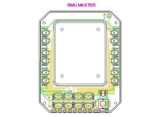
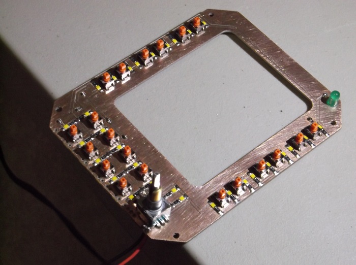
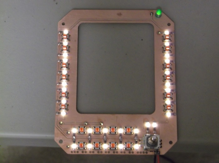
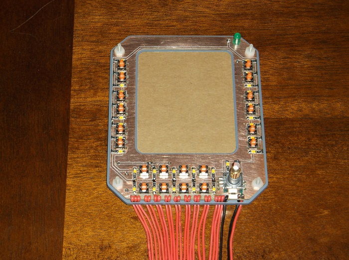
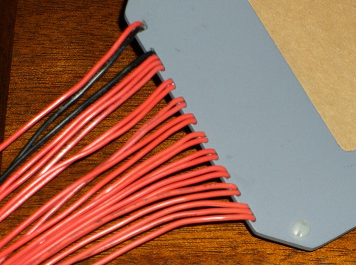
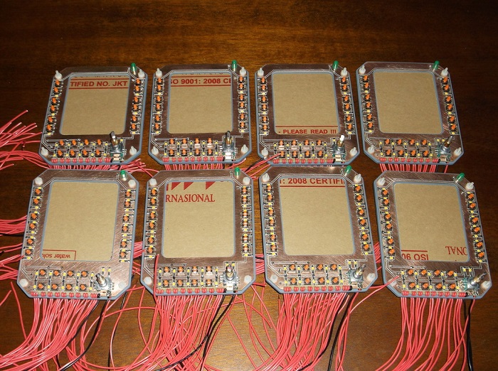
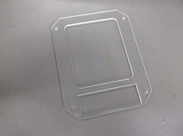
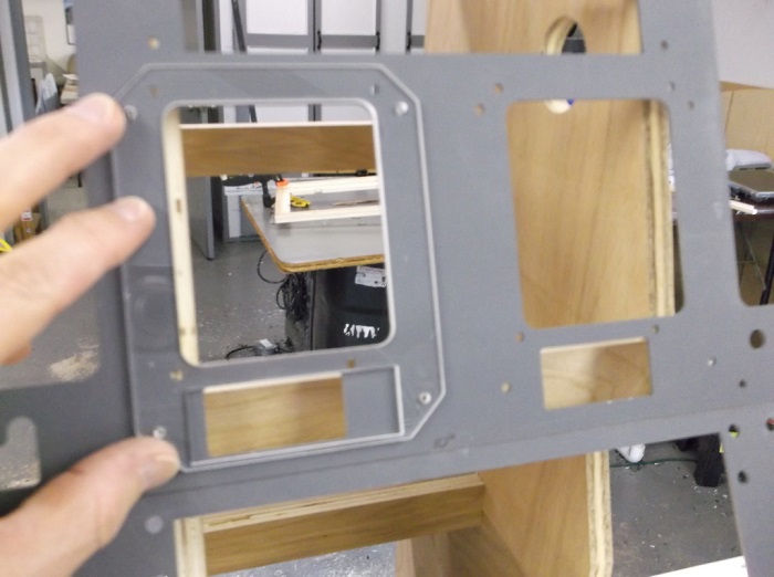
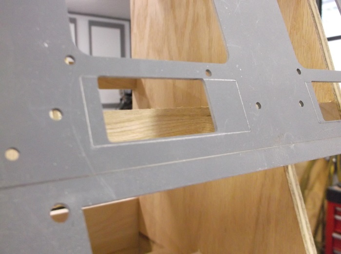
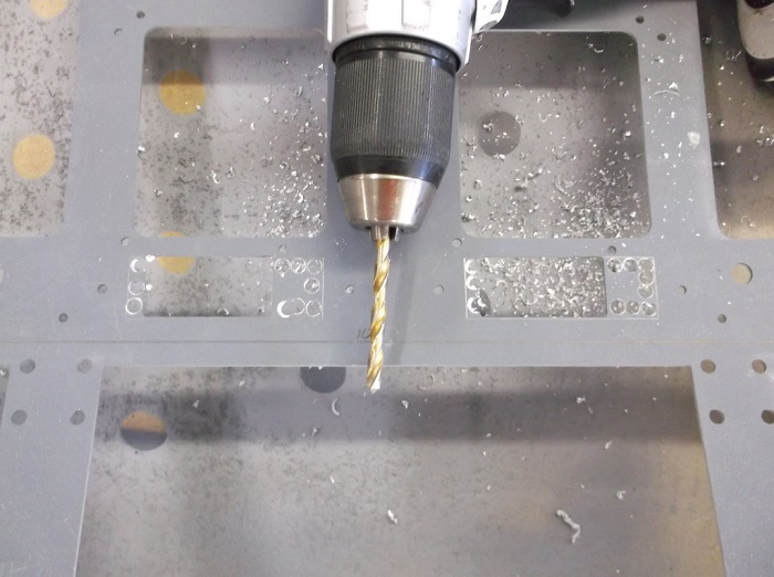
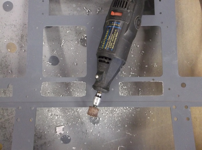
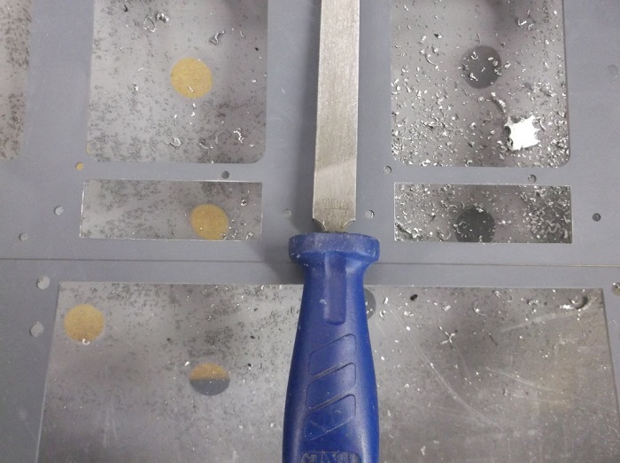
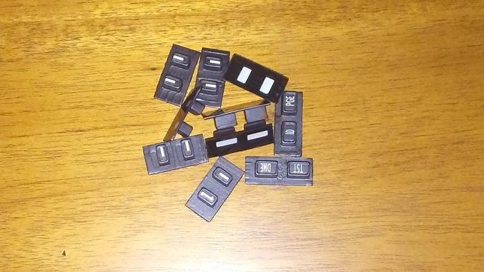
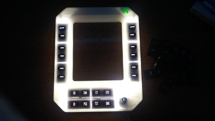
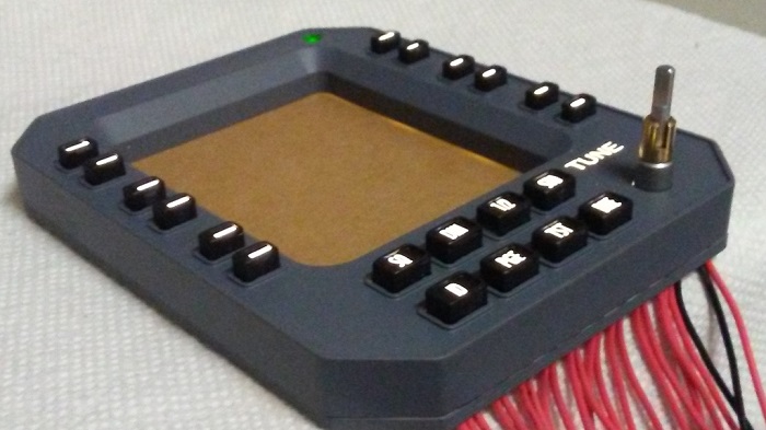
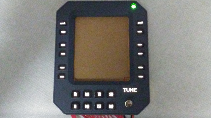
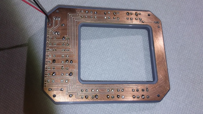

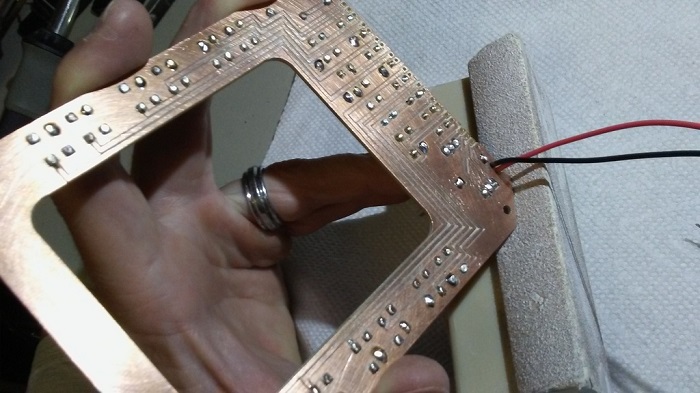
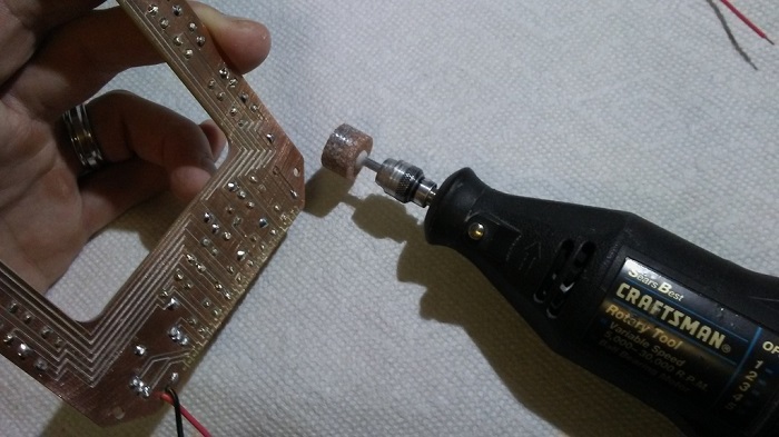
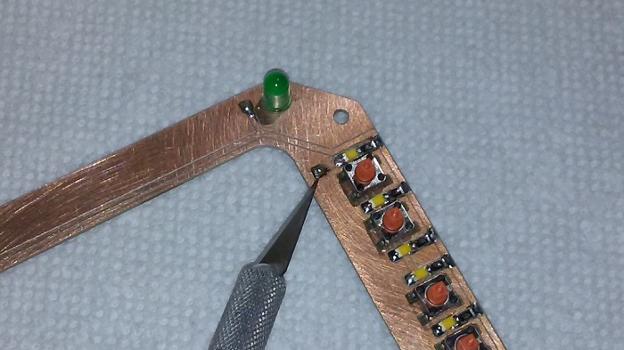
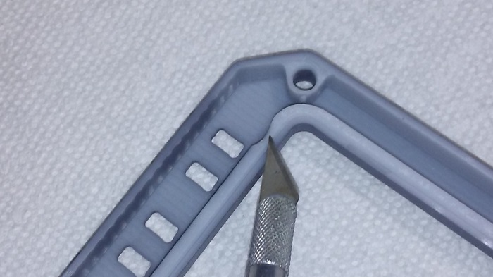
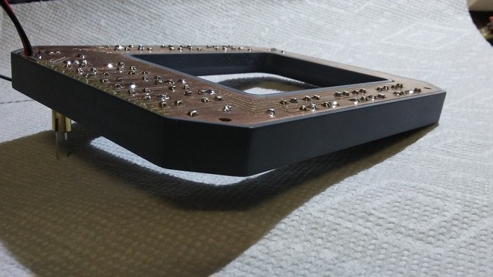
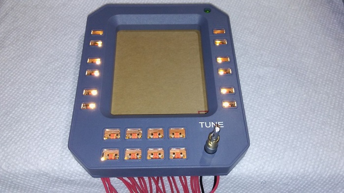
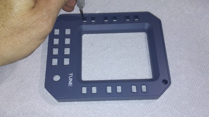
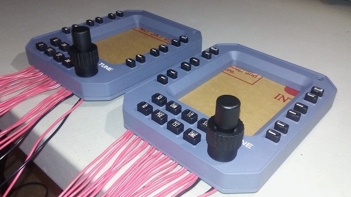
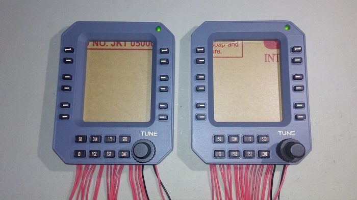
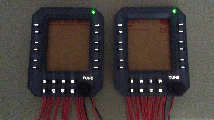
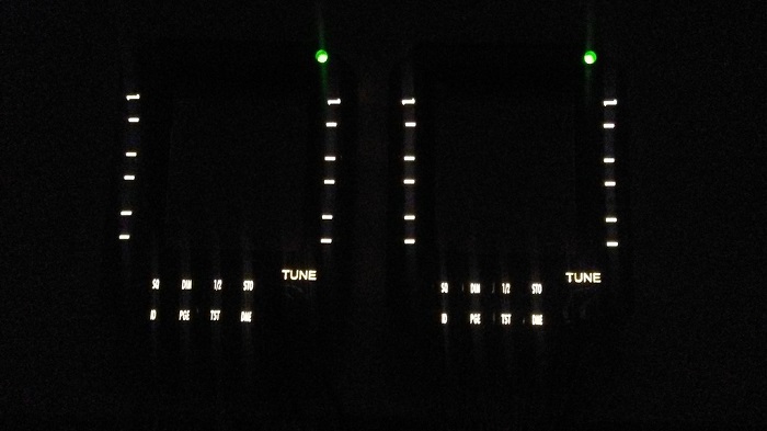
![]()
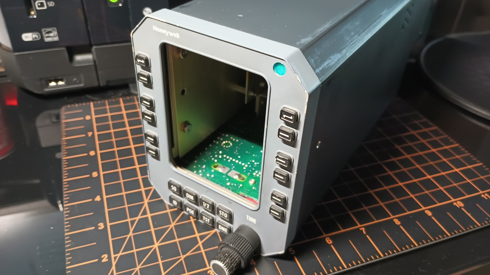

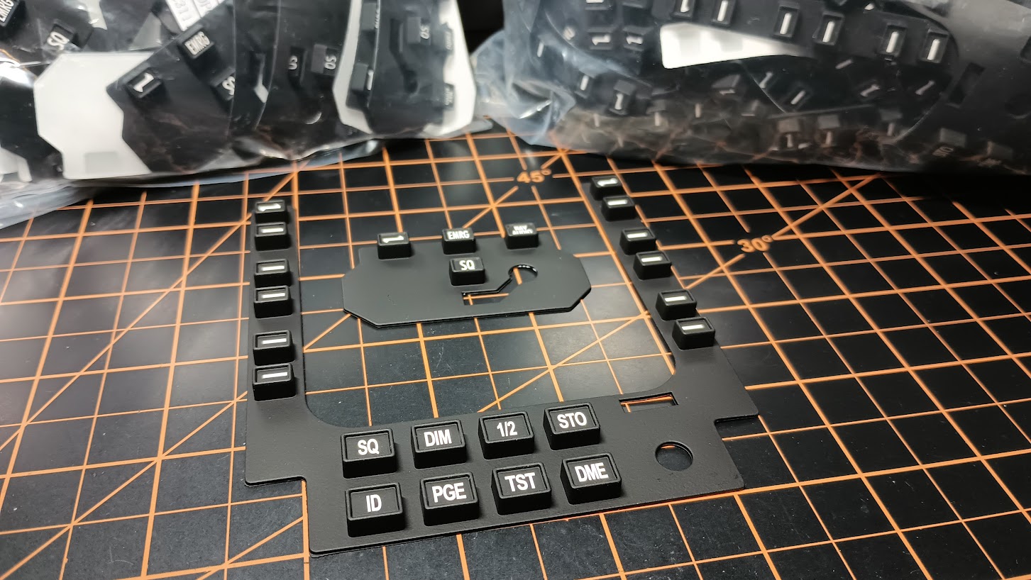
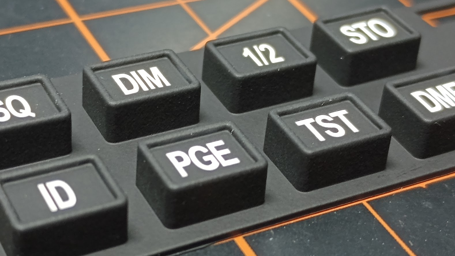
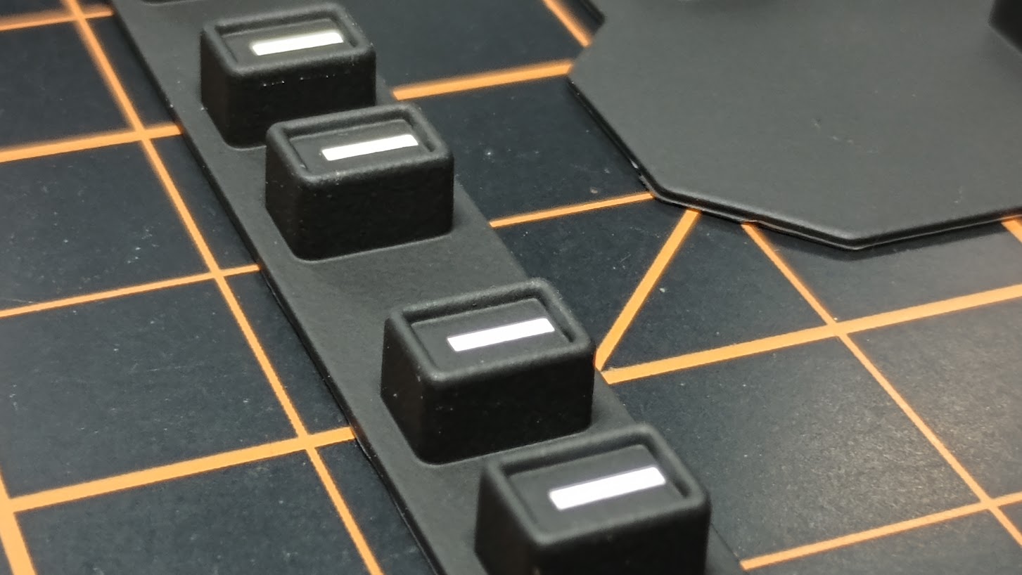
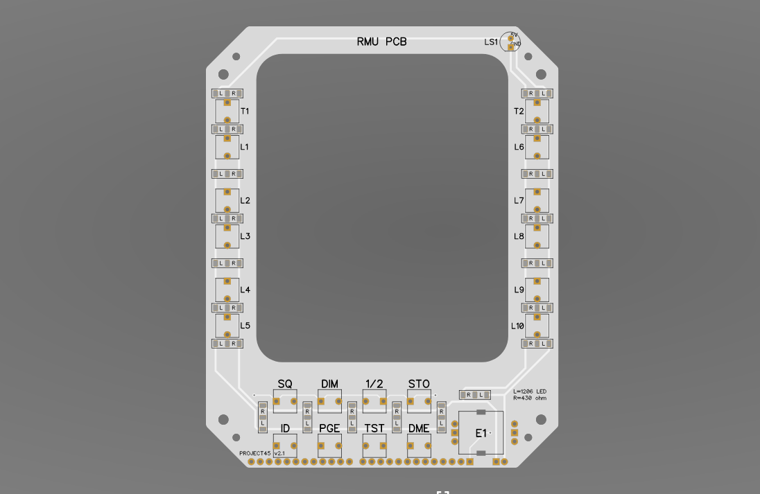
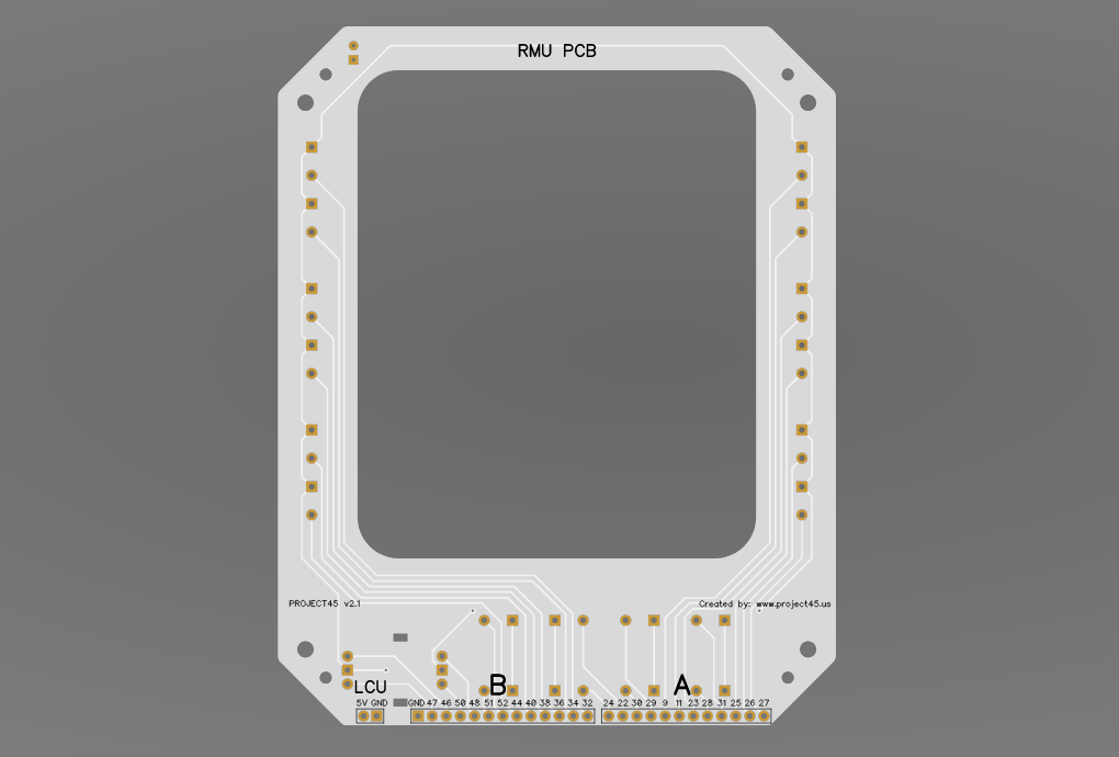
![]()
![]()
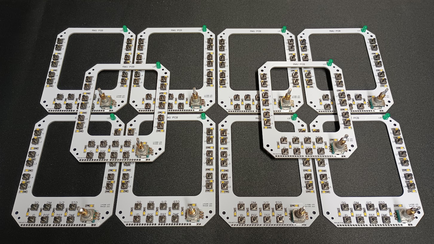
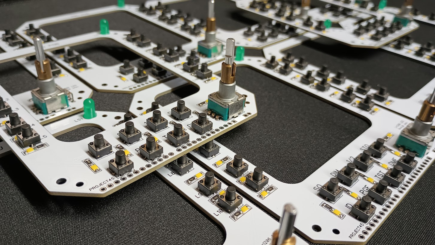
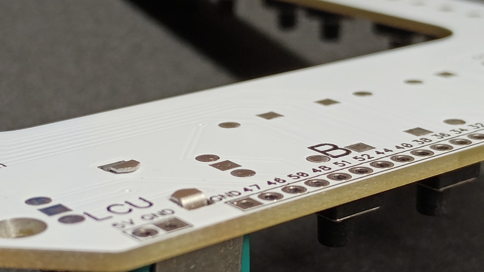
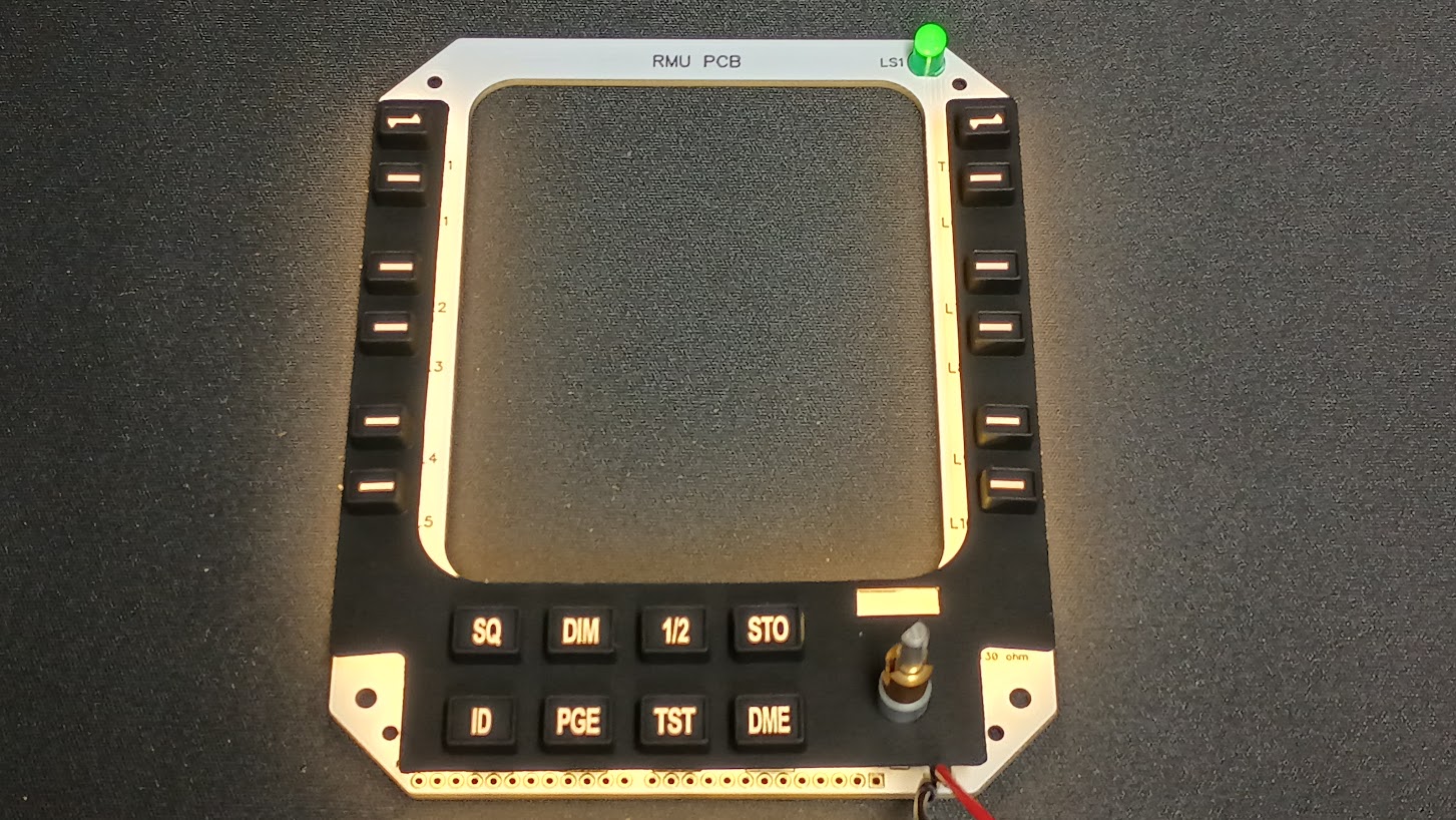
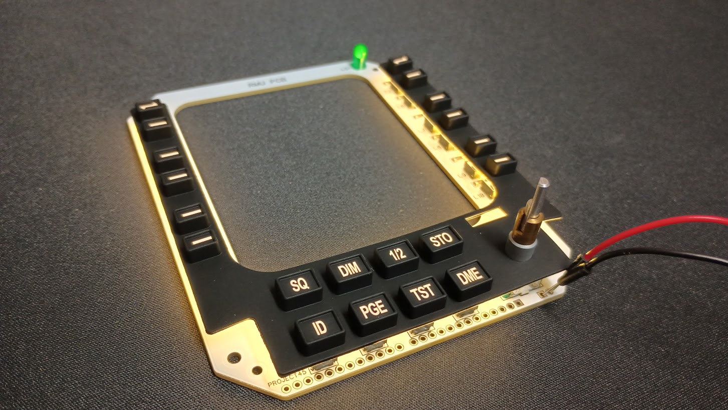
![]()
![]()

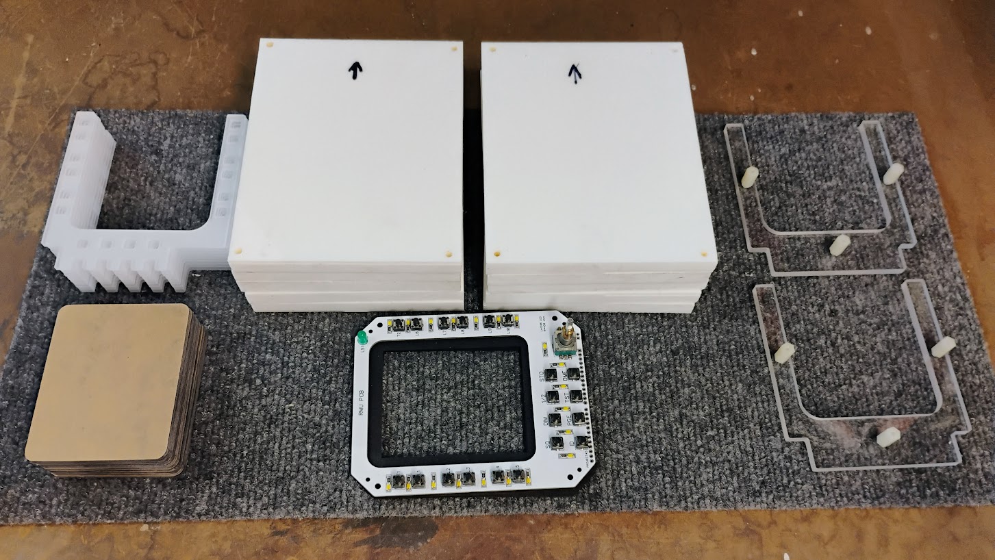
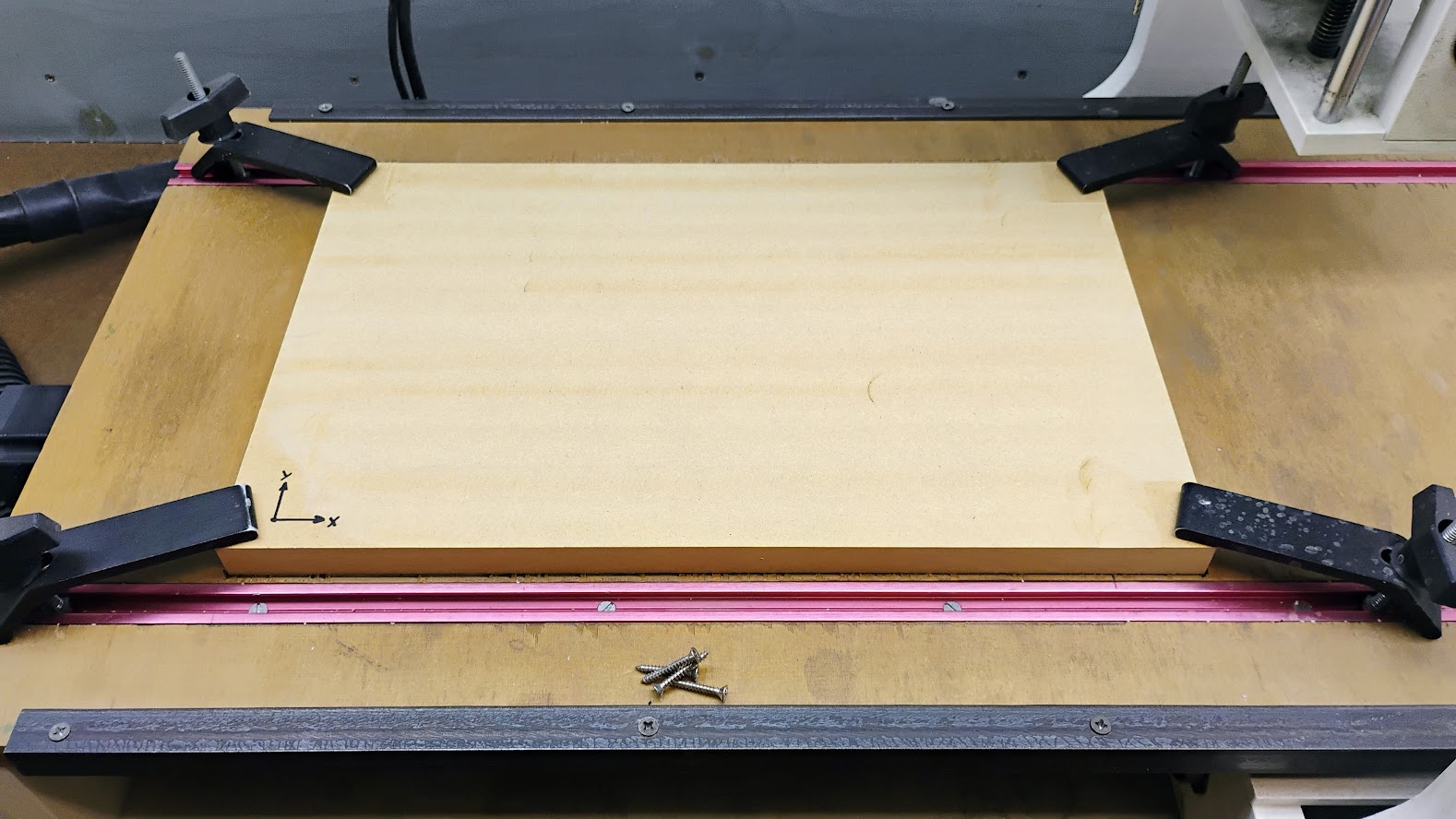
![]()
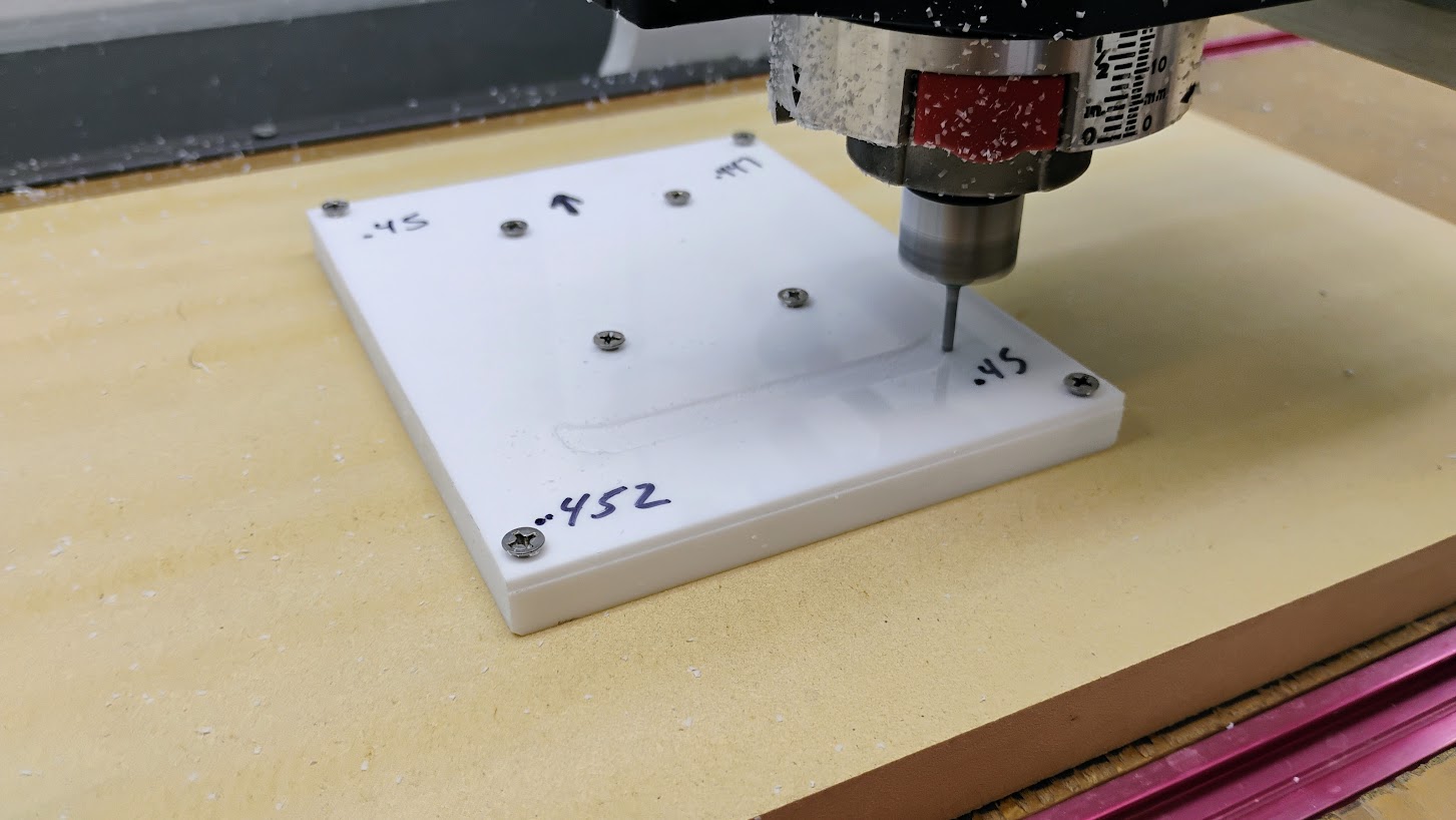
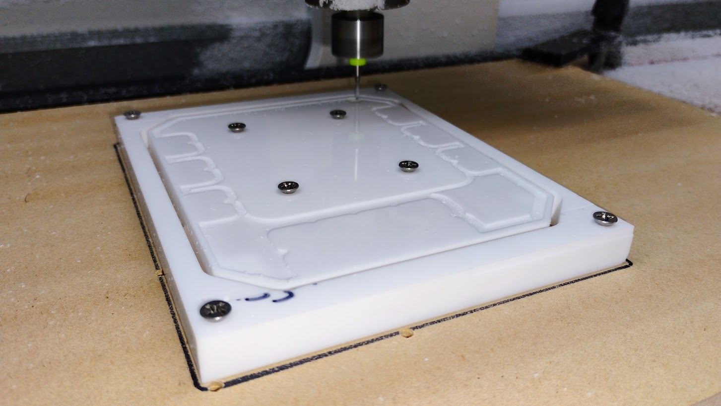
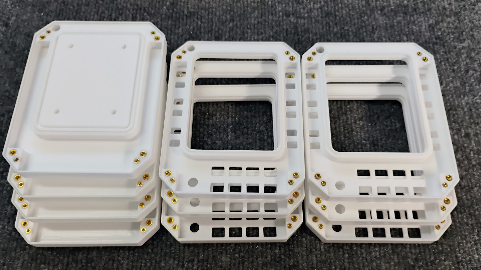
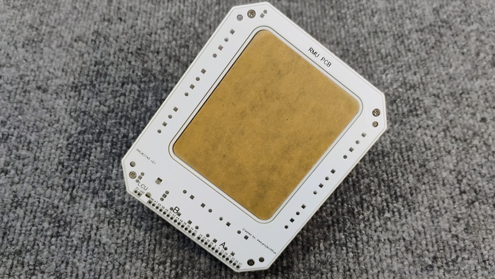
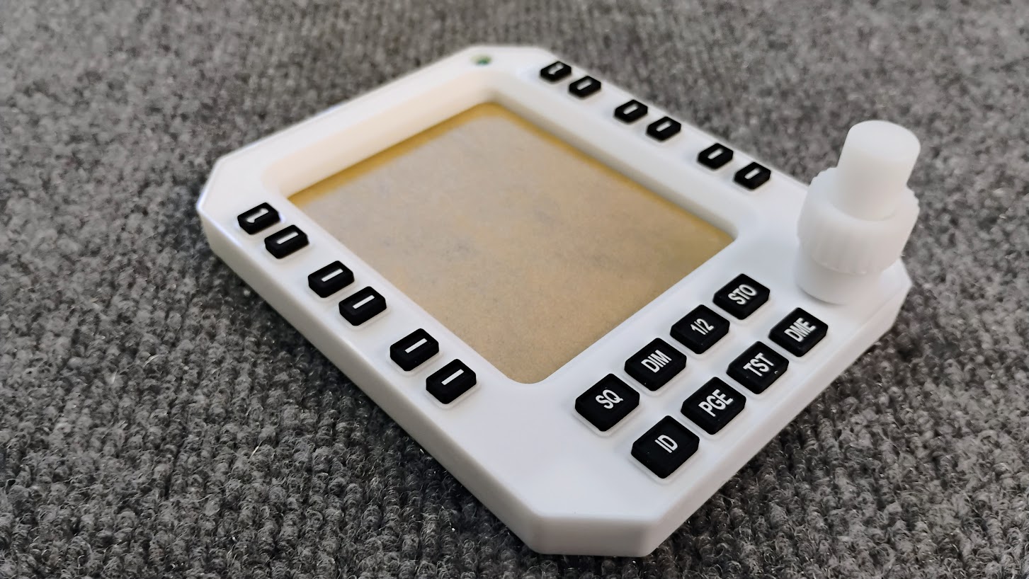
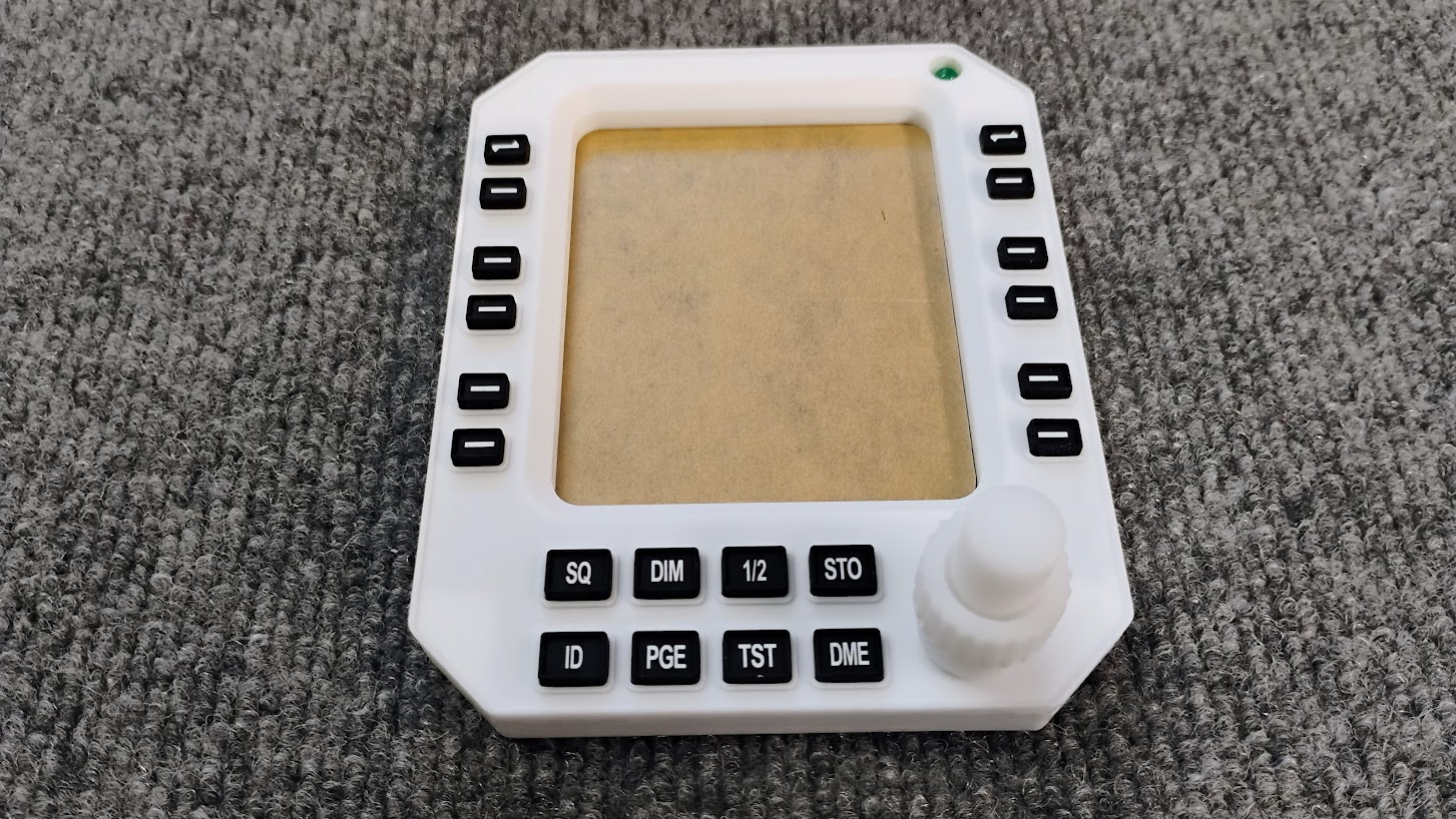
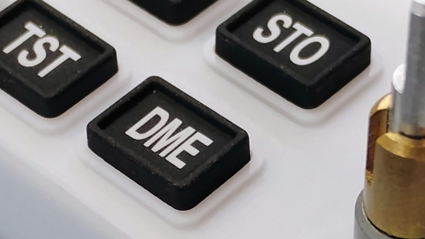
![]()
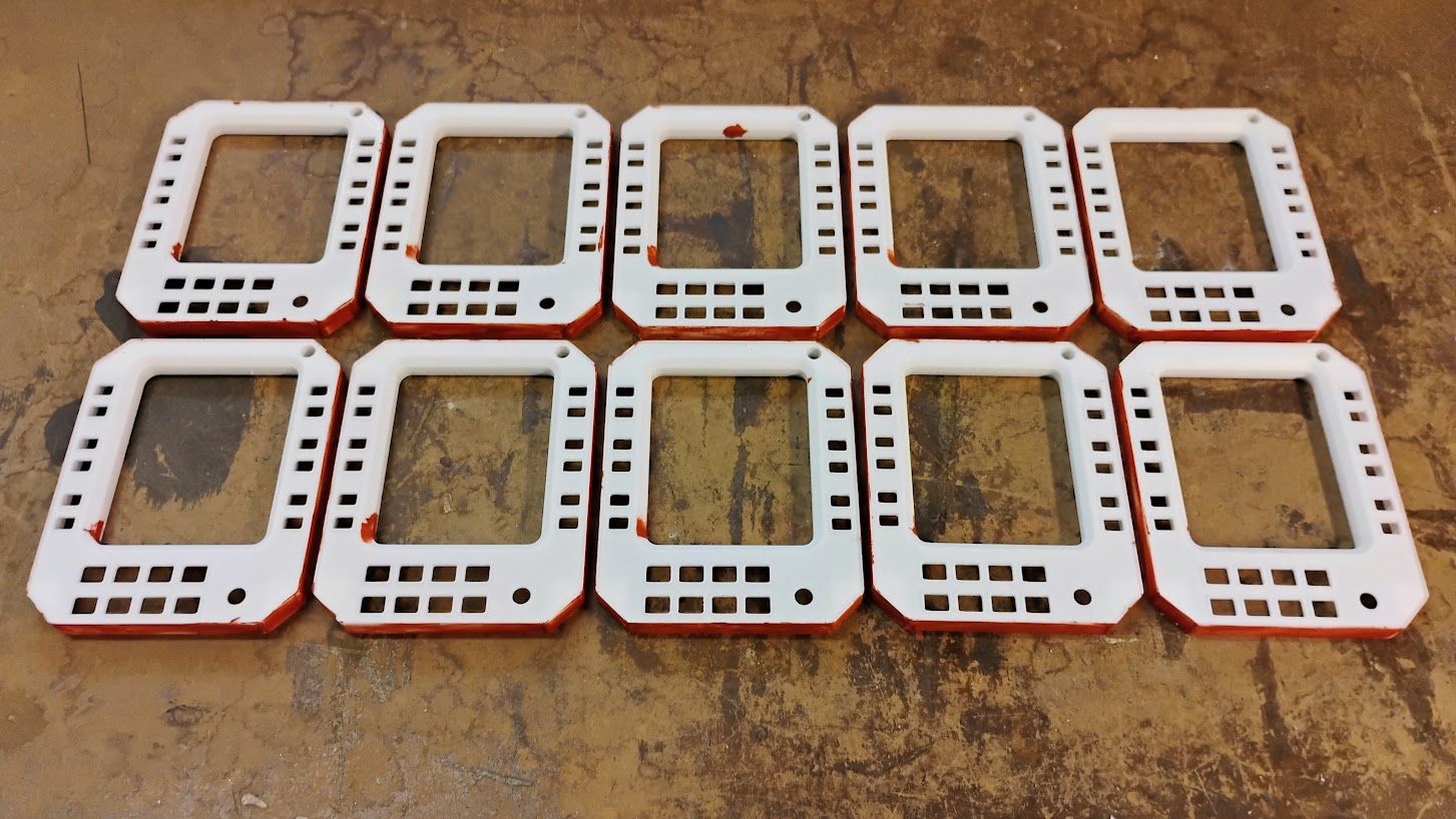
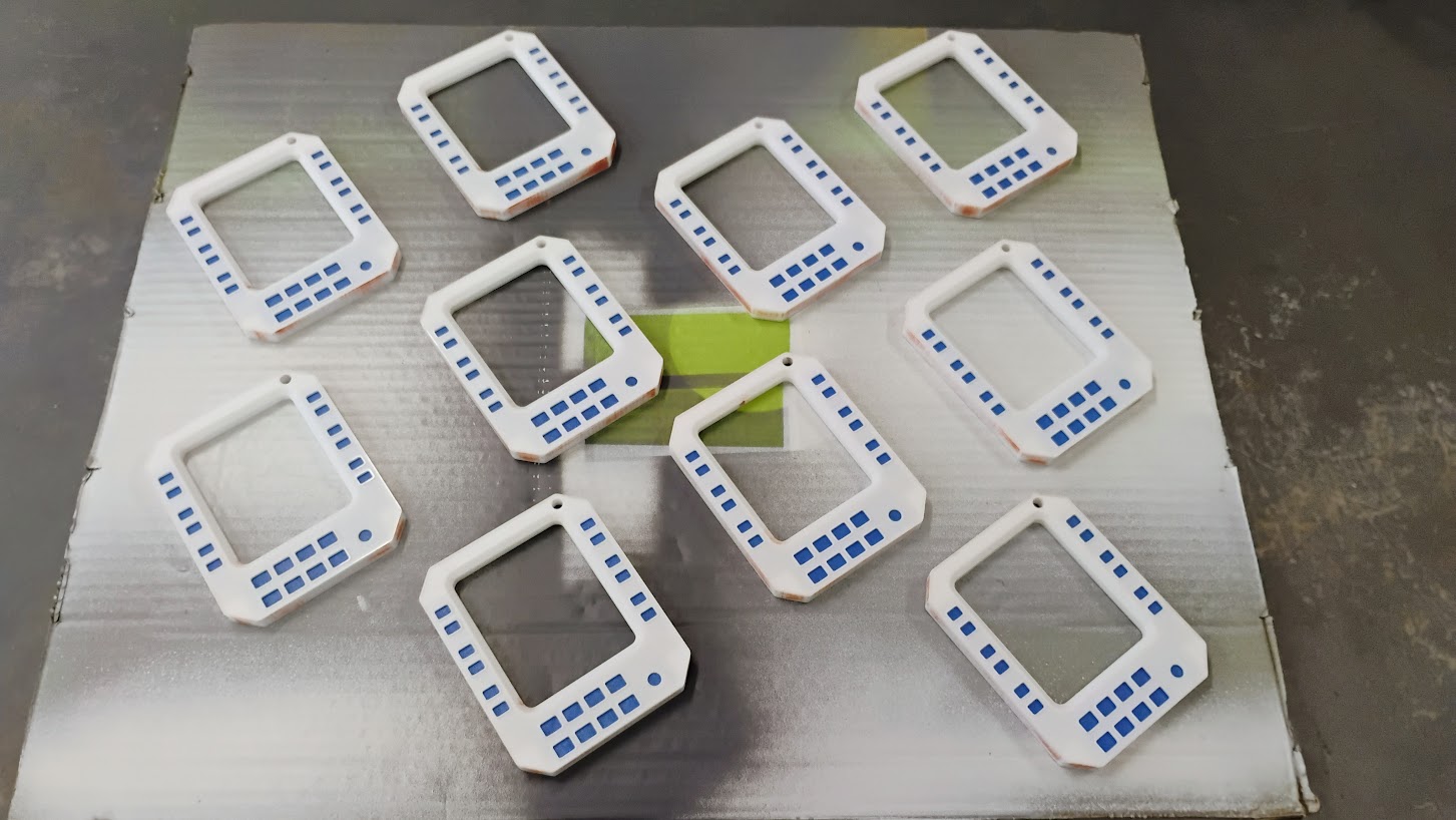
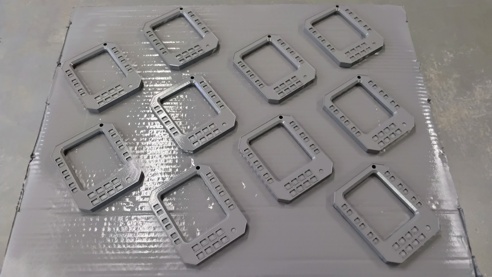
![]()
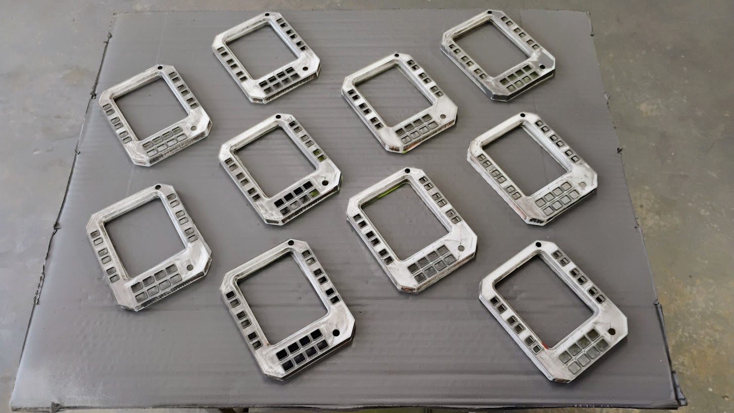
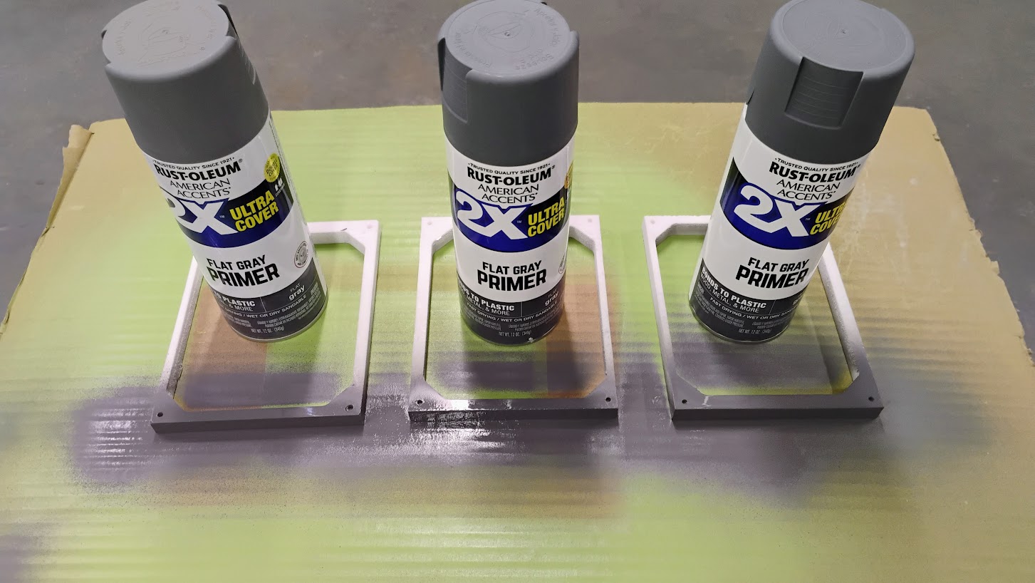
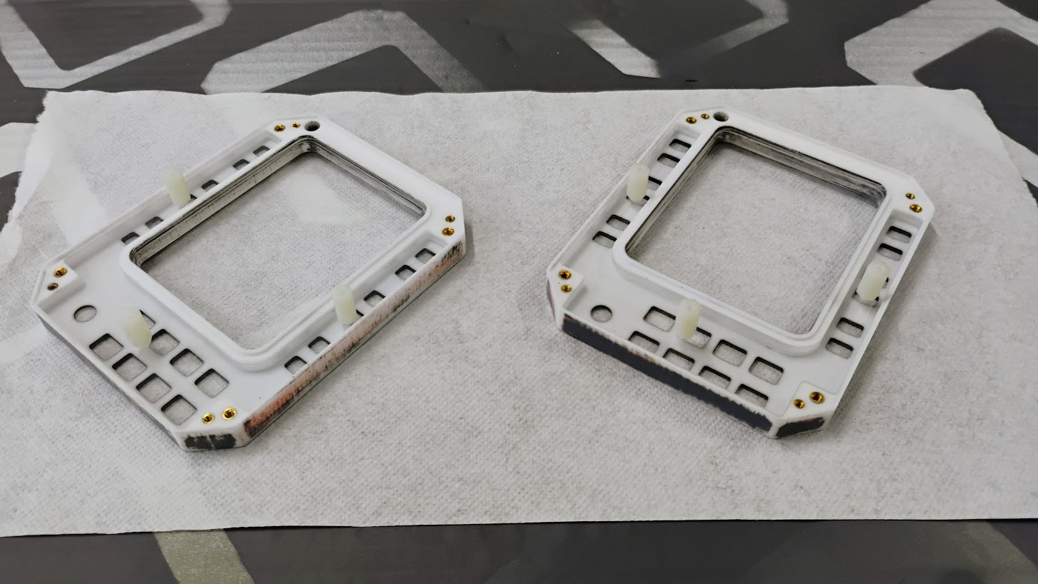
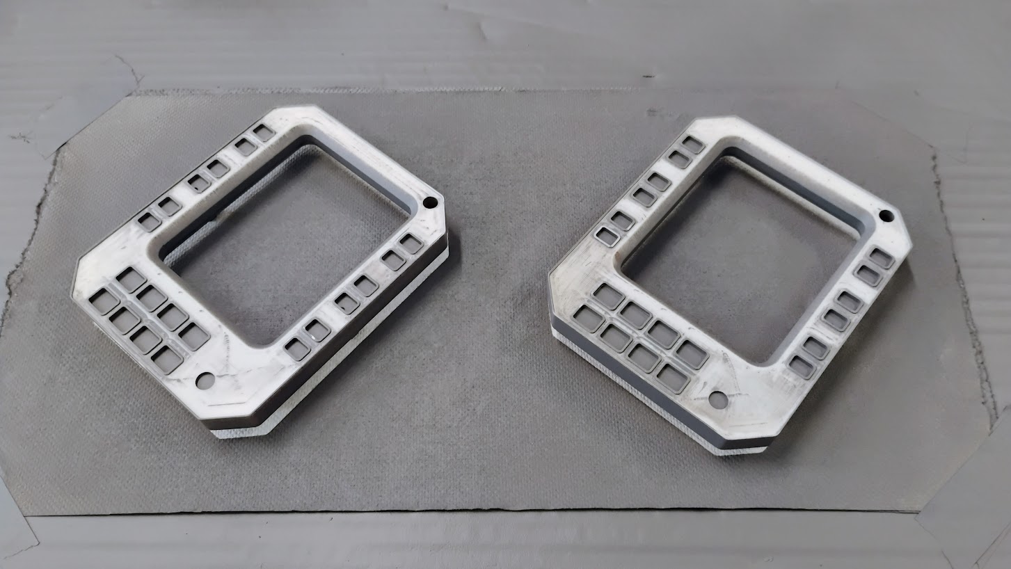
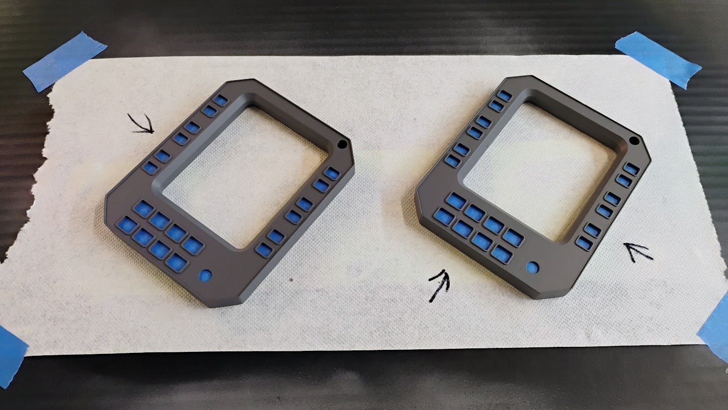
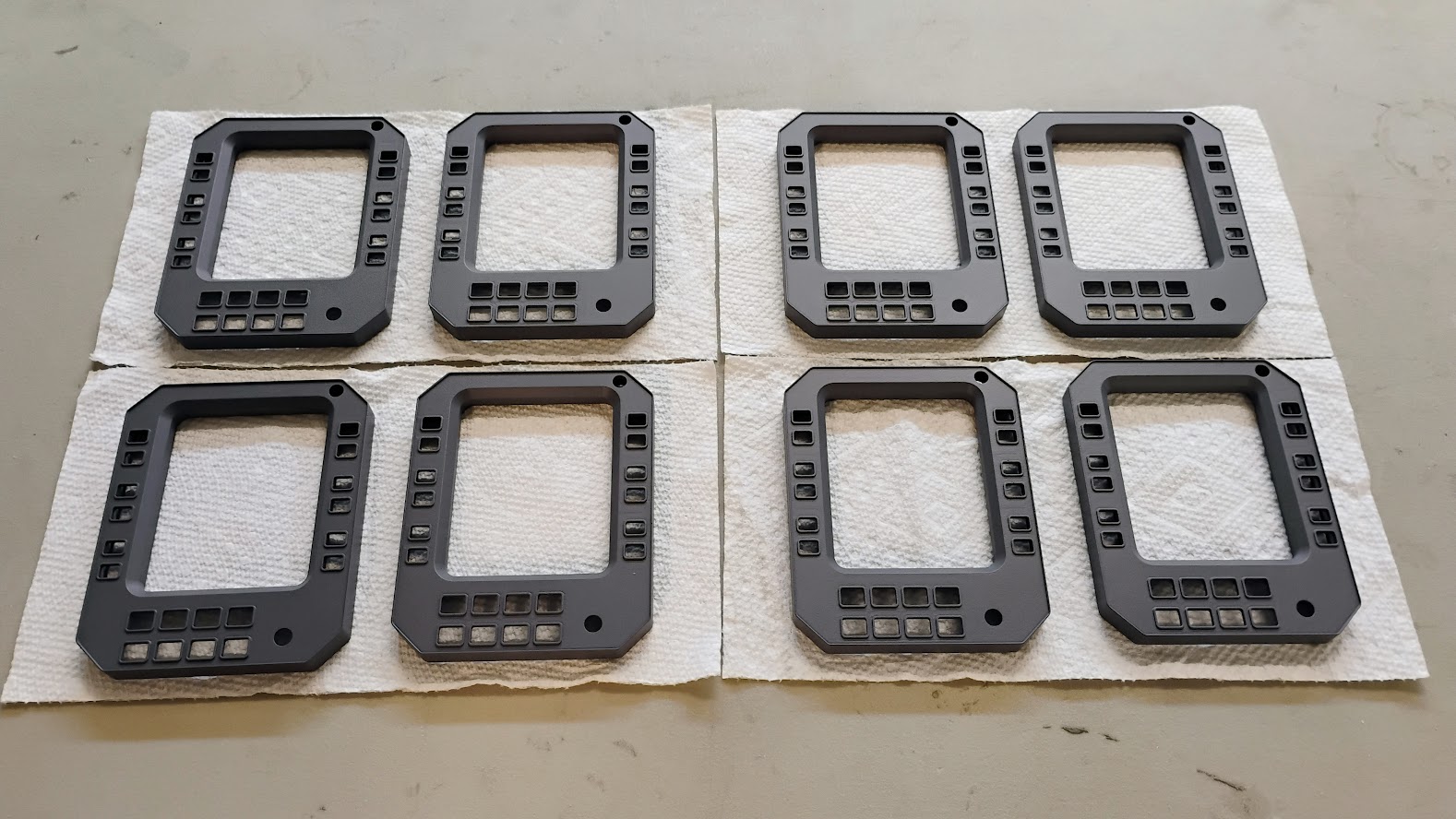
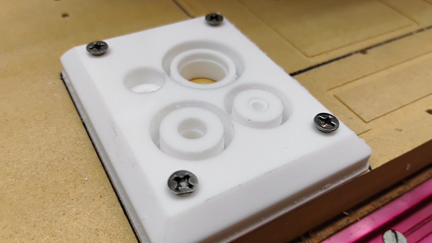
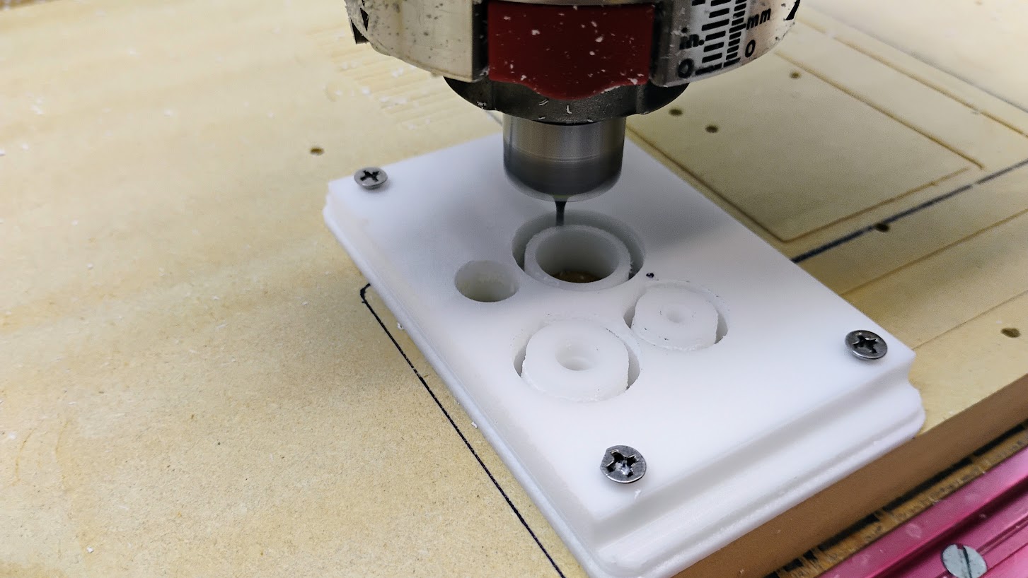

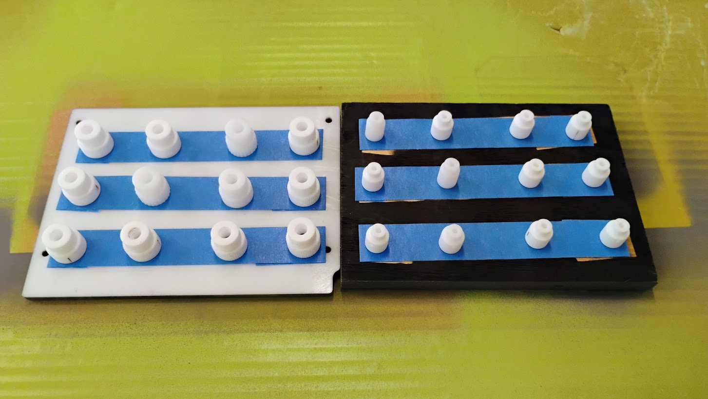
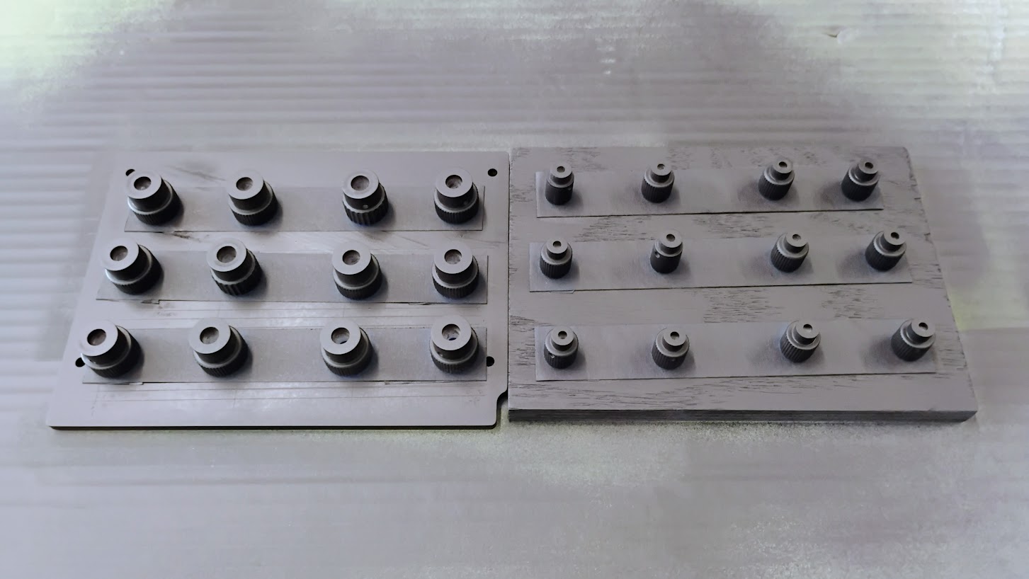
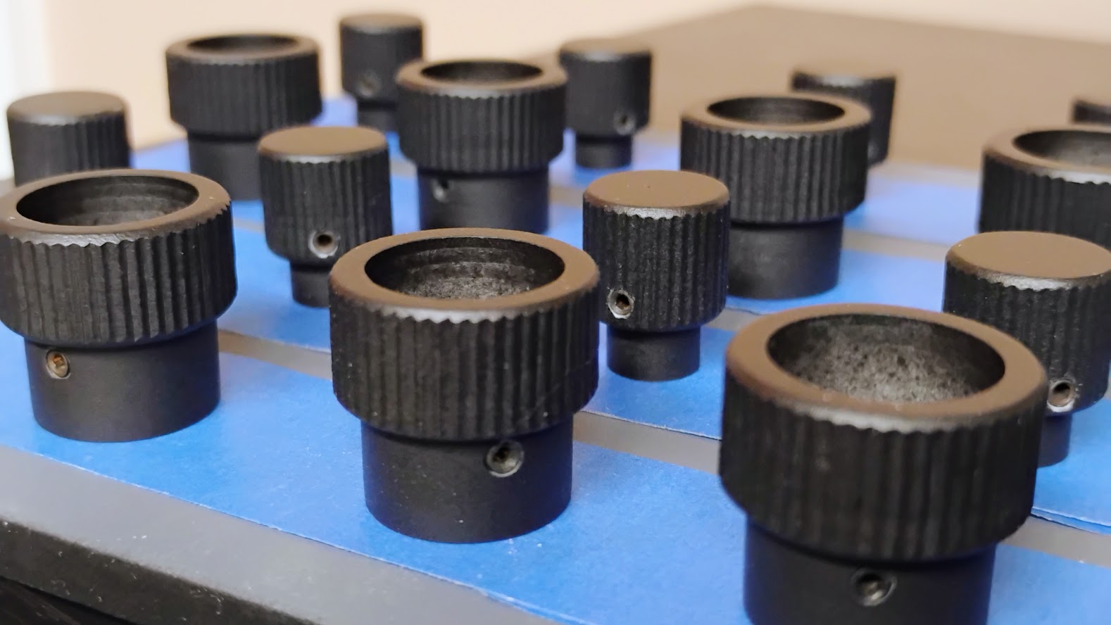
![]()
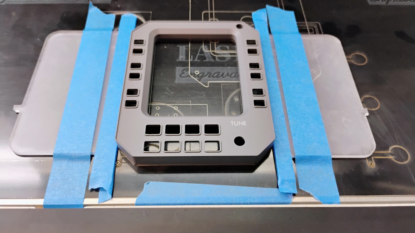
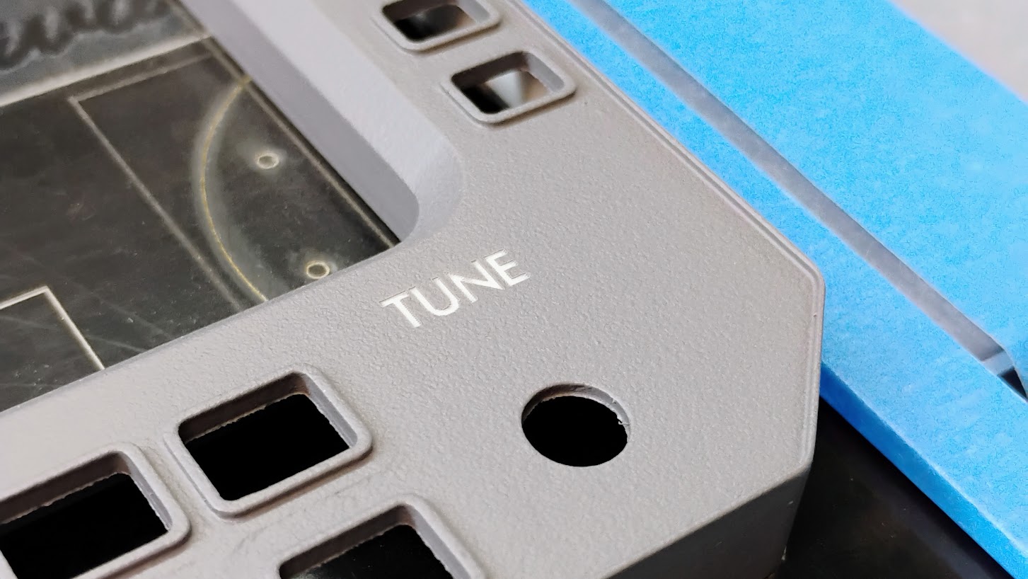
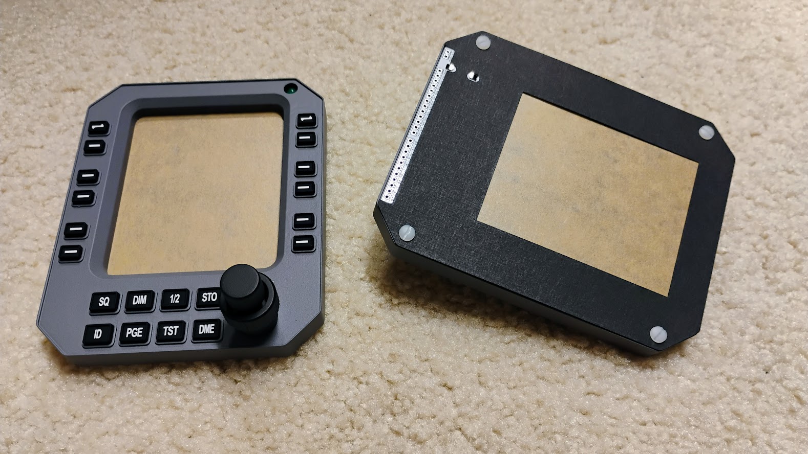
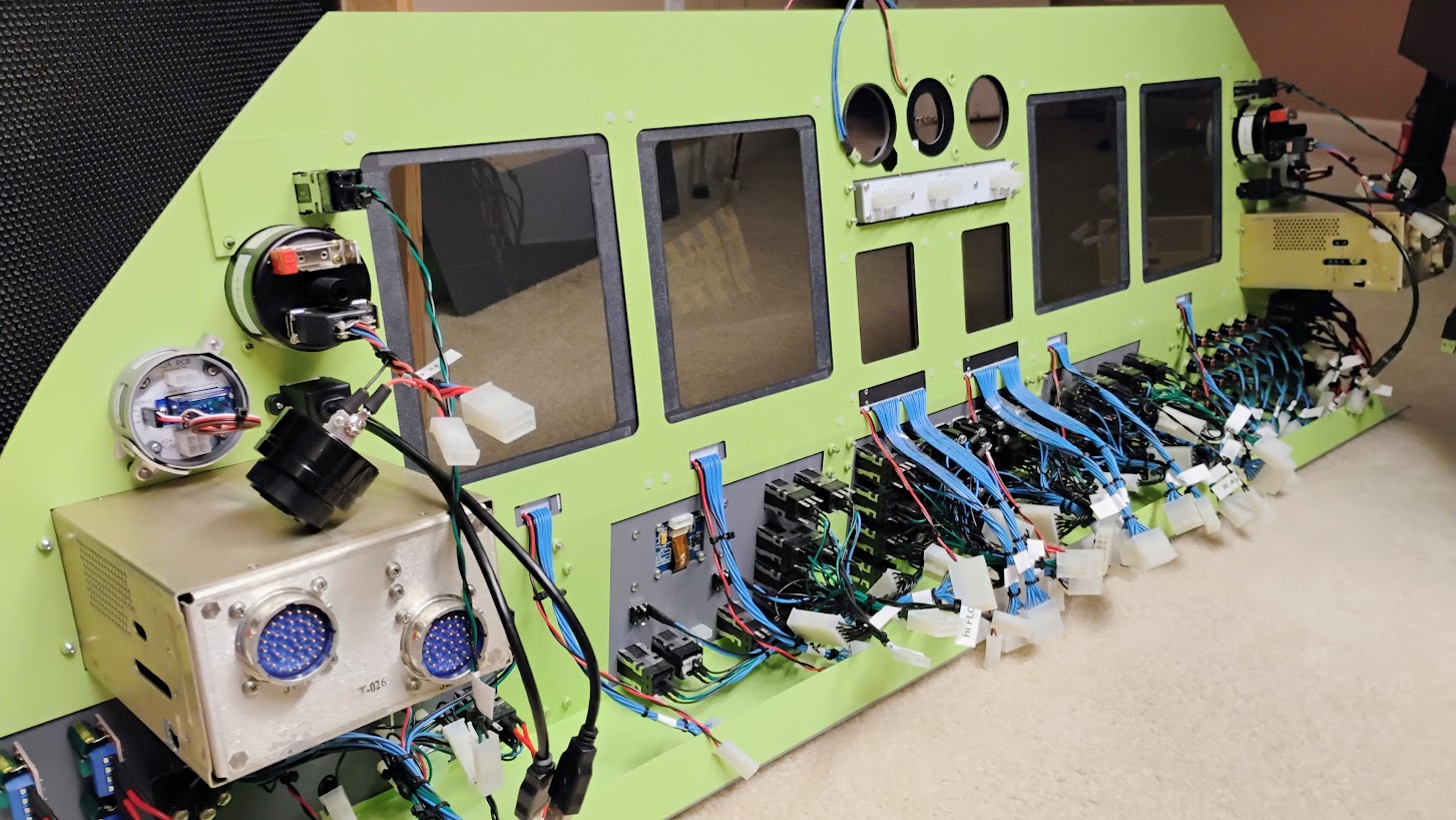
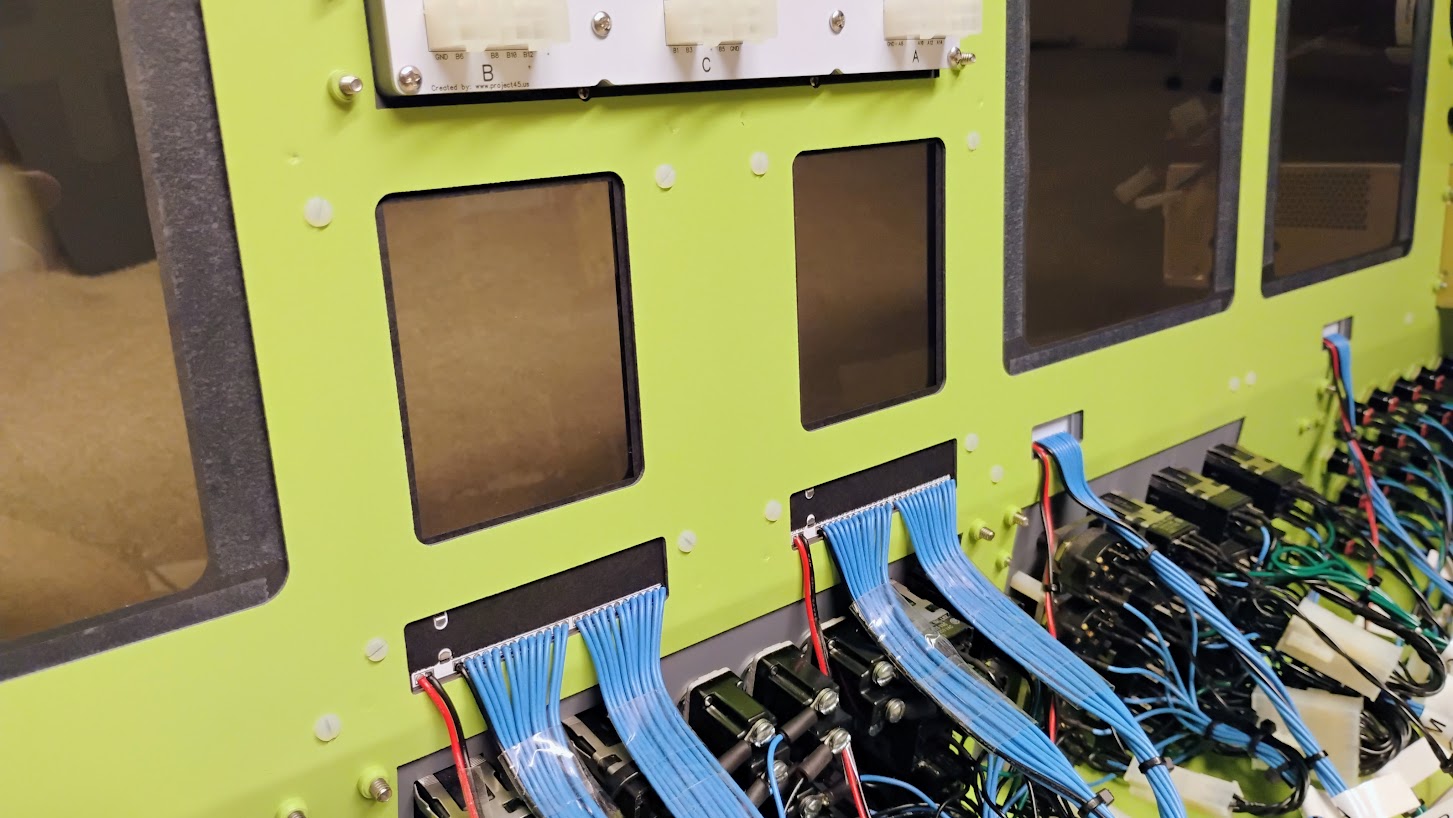
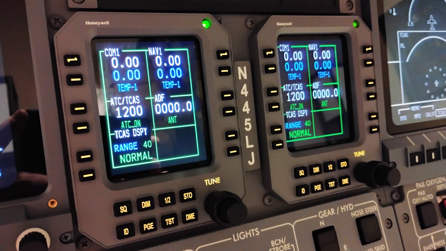
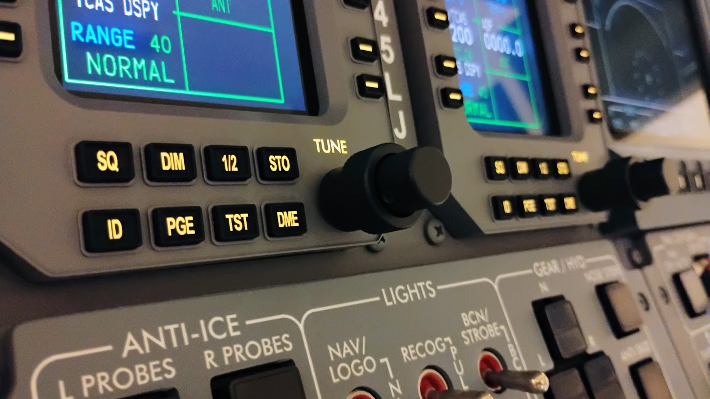
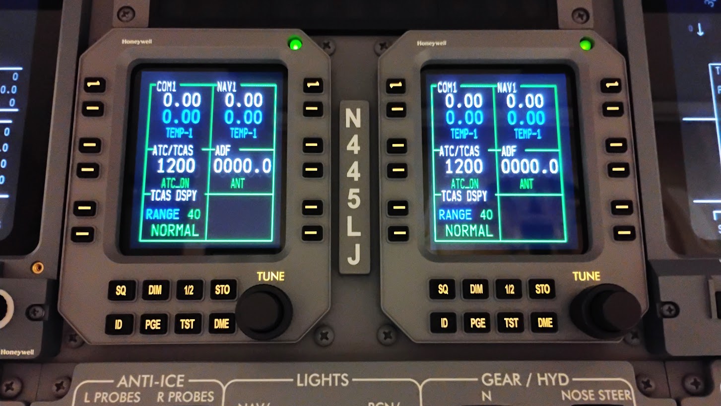
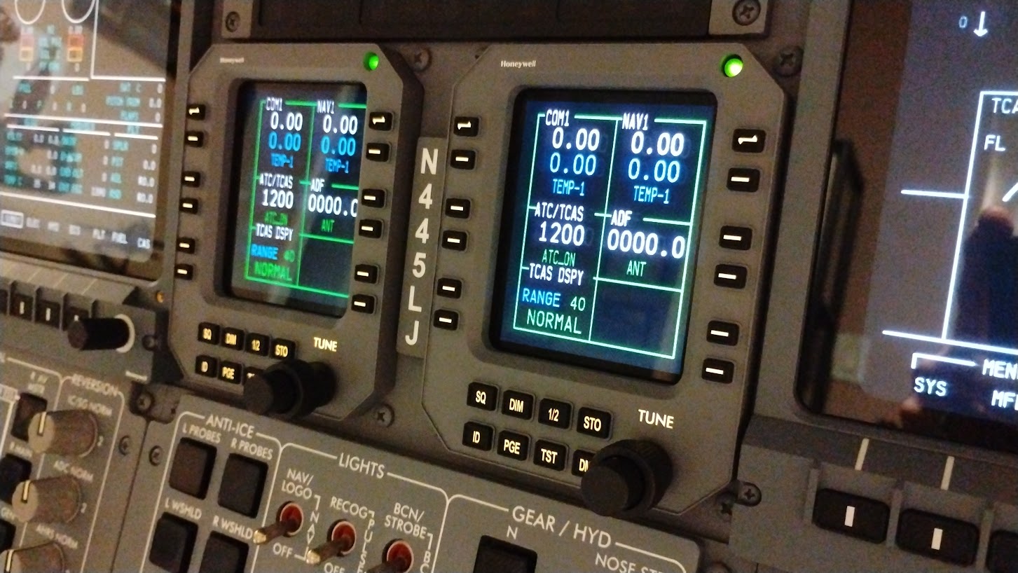
Forum NavigationRMU Development by Project45
![]() #1 · November 19, 2023, 4:42 pm
#1 · November 19, 2023, 4:42 pm![]() #2 · November 19, 2023, 8:50 pm
#2 · November 19, 2023, 8:50 pm![]() #3 · November 20, 2023, 7:30 pm
#3 · November 20, 2023, 7:30 pm![]() #4 · January 7, 2024, 12:50 am
#4 · January 7, 2024, 12:50 am![]() #5 · January 7, 2024, 8:30 pmRon Rollo has reacted to this post.Ron Rollo
#5 · January 7, 2024, 8:30 pmRon Rollo has reacted to this post.Ron Rollo![]() #6 · February 28, 2025, 10:54 pmTerryC has reacted to this post.TerryC
#6 · February 28, 2025, 10:54 pmTerryC has reacted to this post.TerryC![]() #7 · March 7, 2025, 9:11 pmWill_S has reacted to this post.Will_S
#7 · March 7, 2025, 9:11 pmWill_S has reacted to this post.Will_S![]() #8 · March 15, 2025, 1:08 amMark Speechley has reacted to this post.Mark Speechley
#8 · March 15, 2025, 1:08 amMark Speechley has reacted to this post.Mark Speechley![]() #9 · March 21, 2025, 2:43 pmMark Speechley and TerryC have reacted to this post.Mark SpeechleyTerryC
#9 · March 21, 2025, 2:43 pmMark Speechley and TerryC have reacted to this post.Mark SpeechleyTerryC![]() #10 · March 26, 2025, 11:25 amHunkaBurninLove and Mark Speechley have reacted to this post.HunkaBurninLoveMark Speechley
#10 · March 26, 2025, 11:25 amHunkaBurninLove and Mark Speechley have reacted to this post.HunkaBurninLoveMark Speechley
2017-10-10