


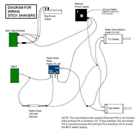
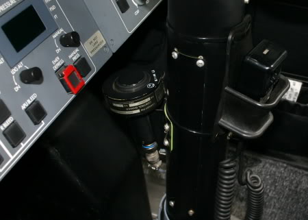
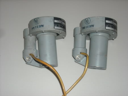
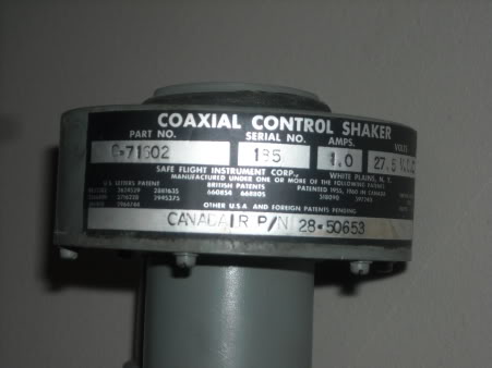
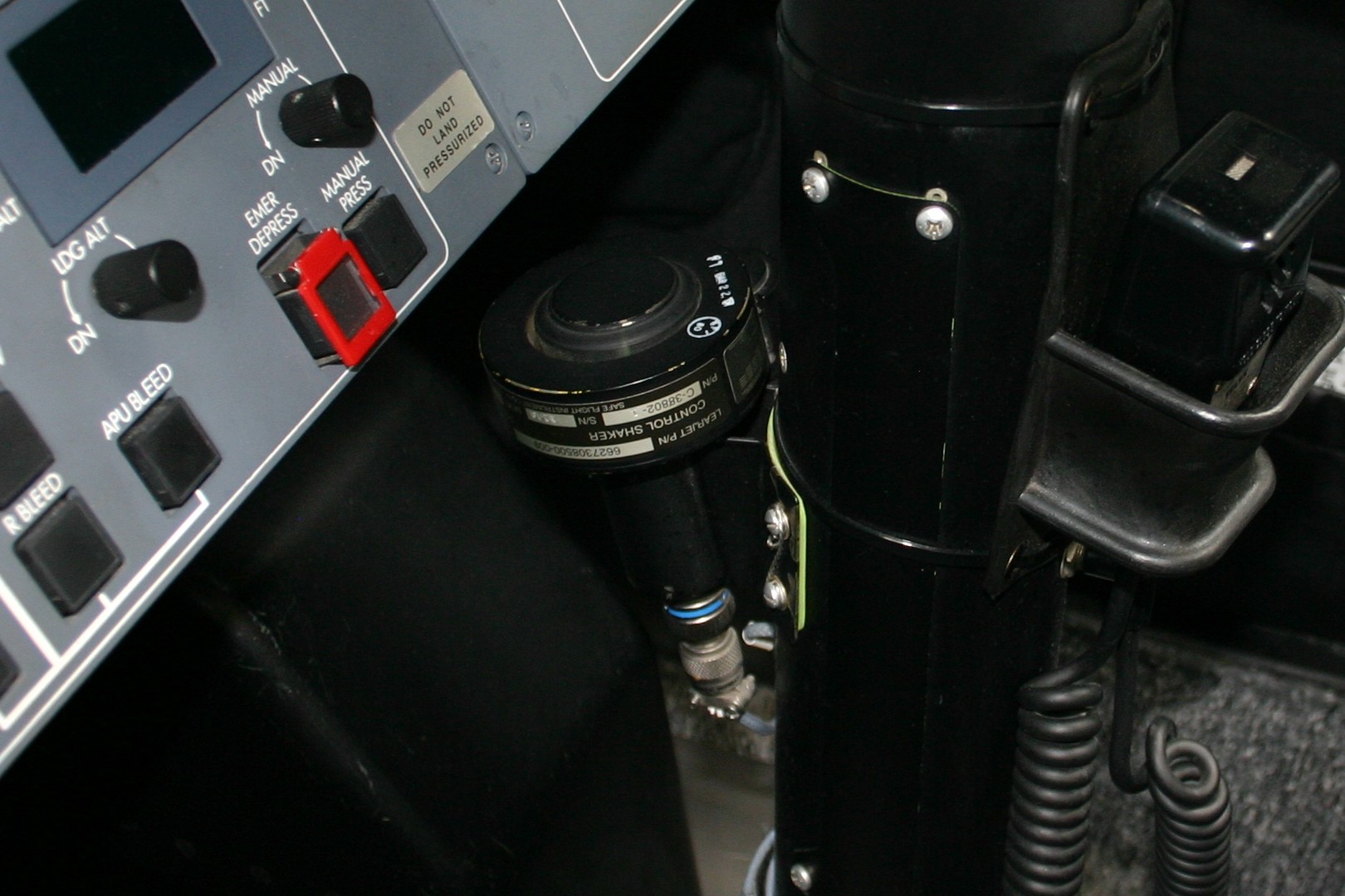
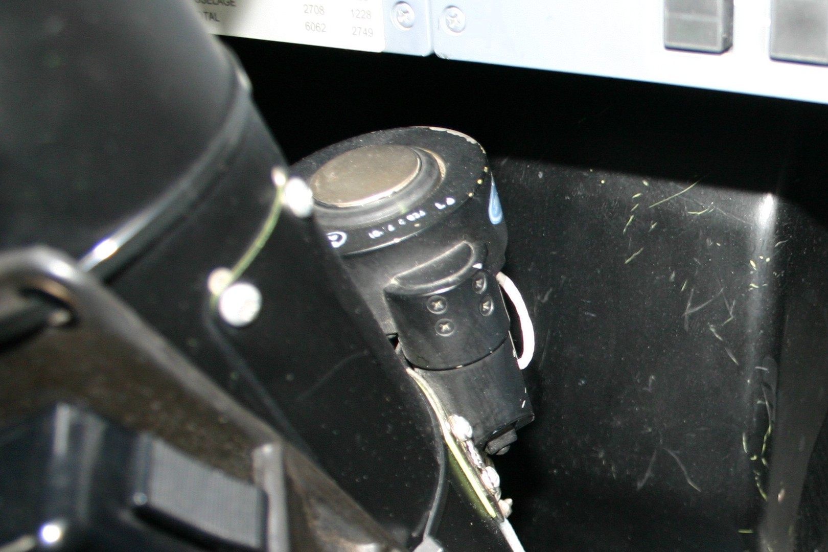
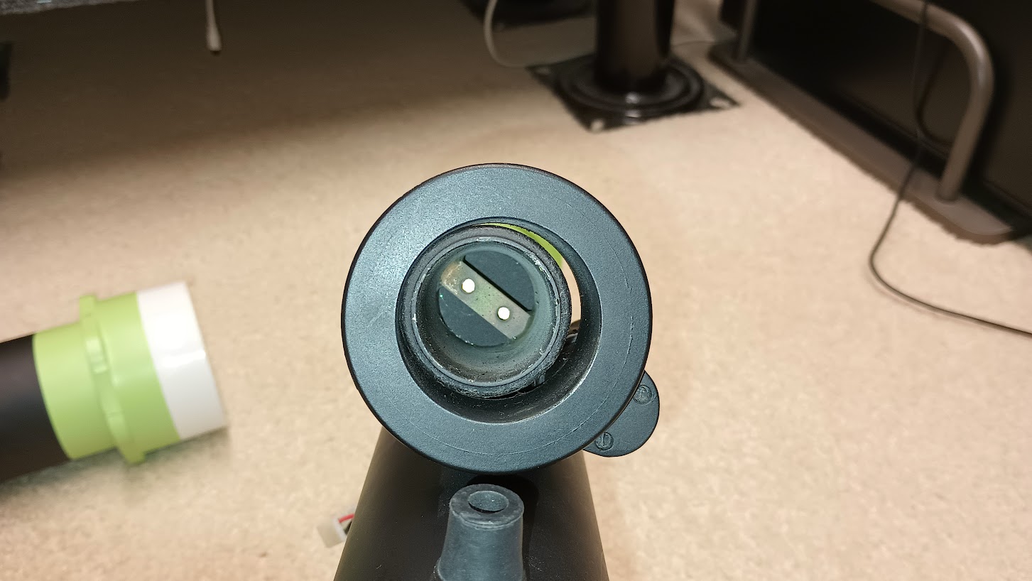
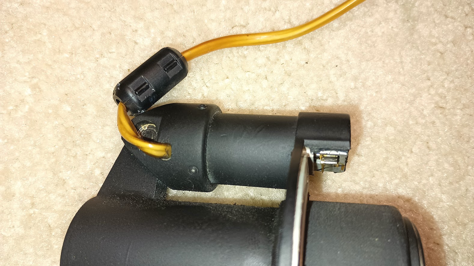
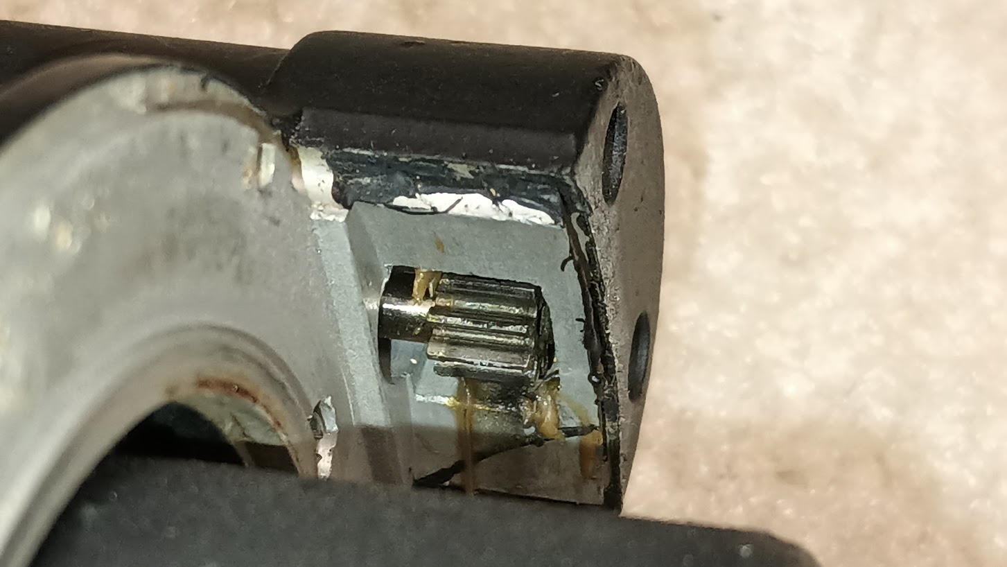
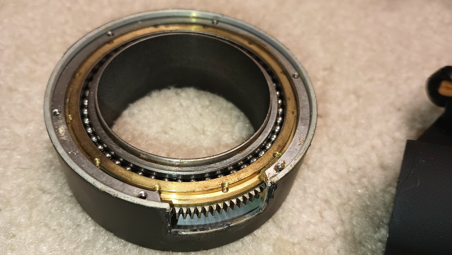
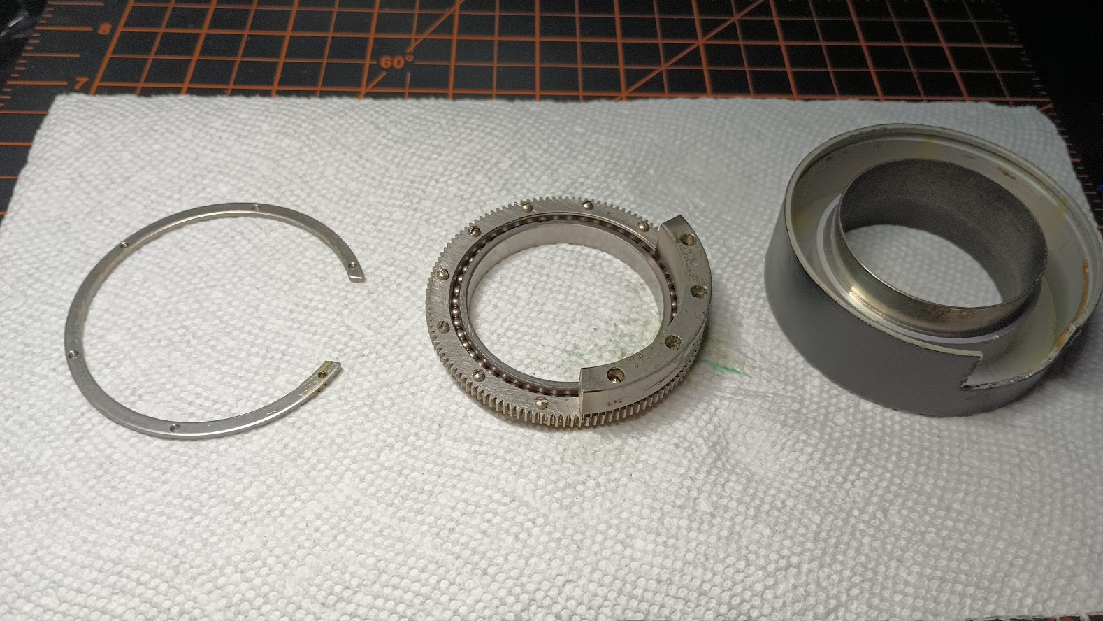
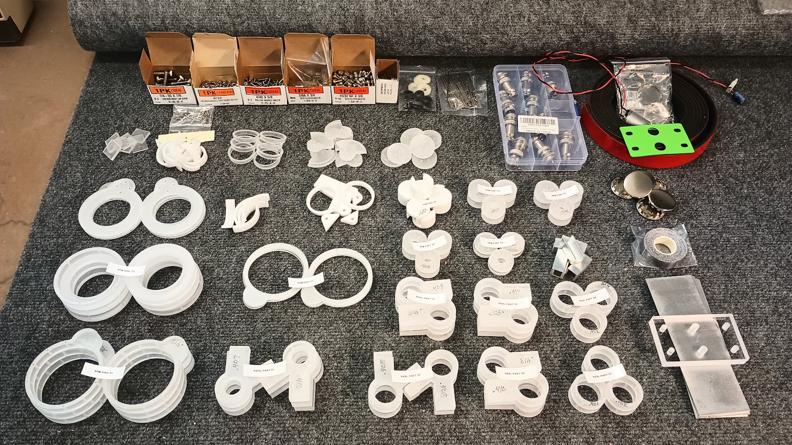
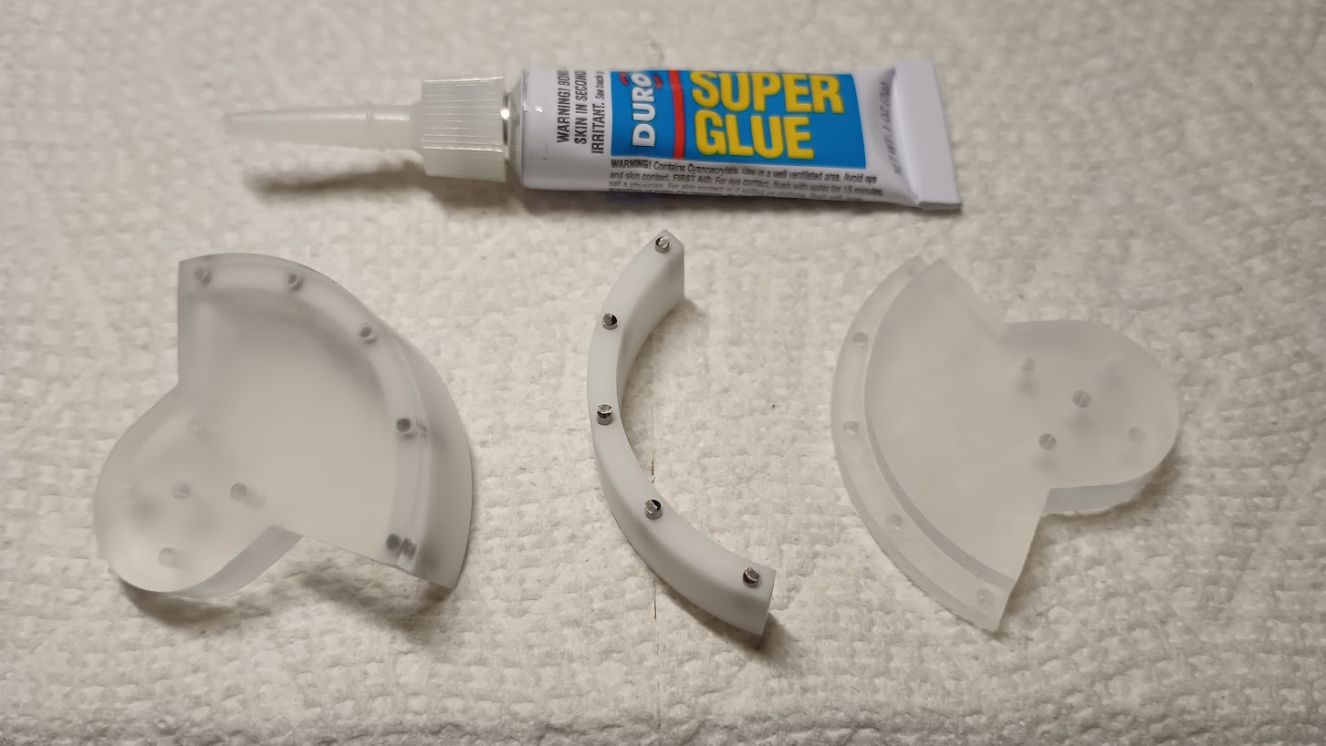
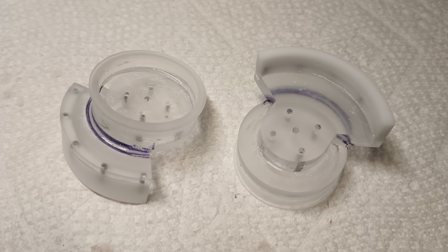
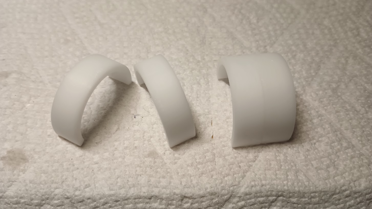
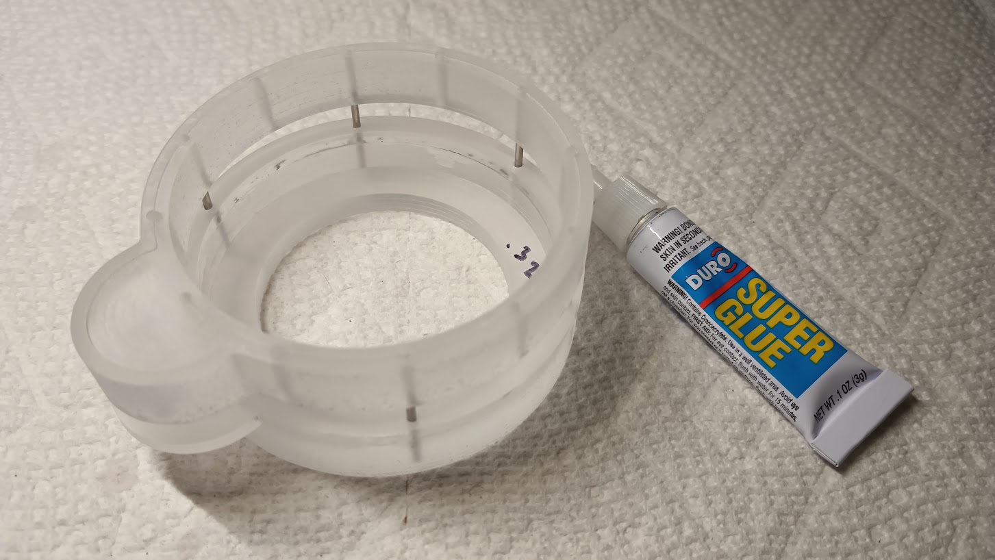
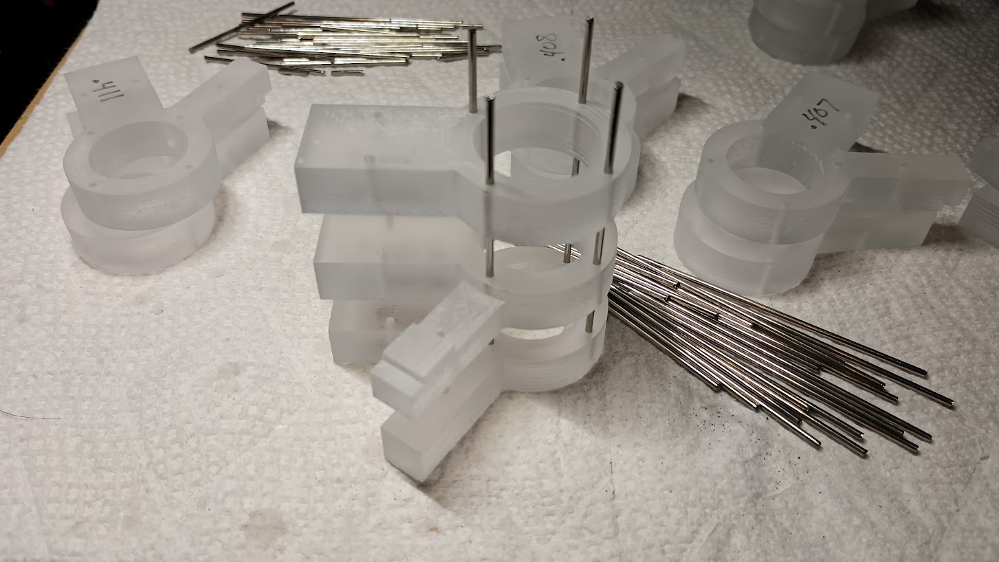
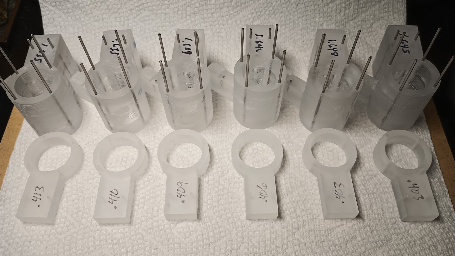
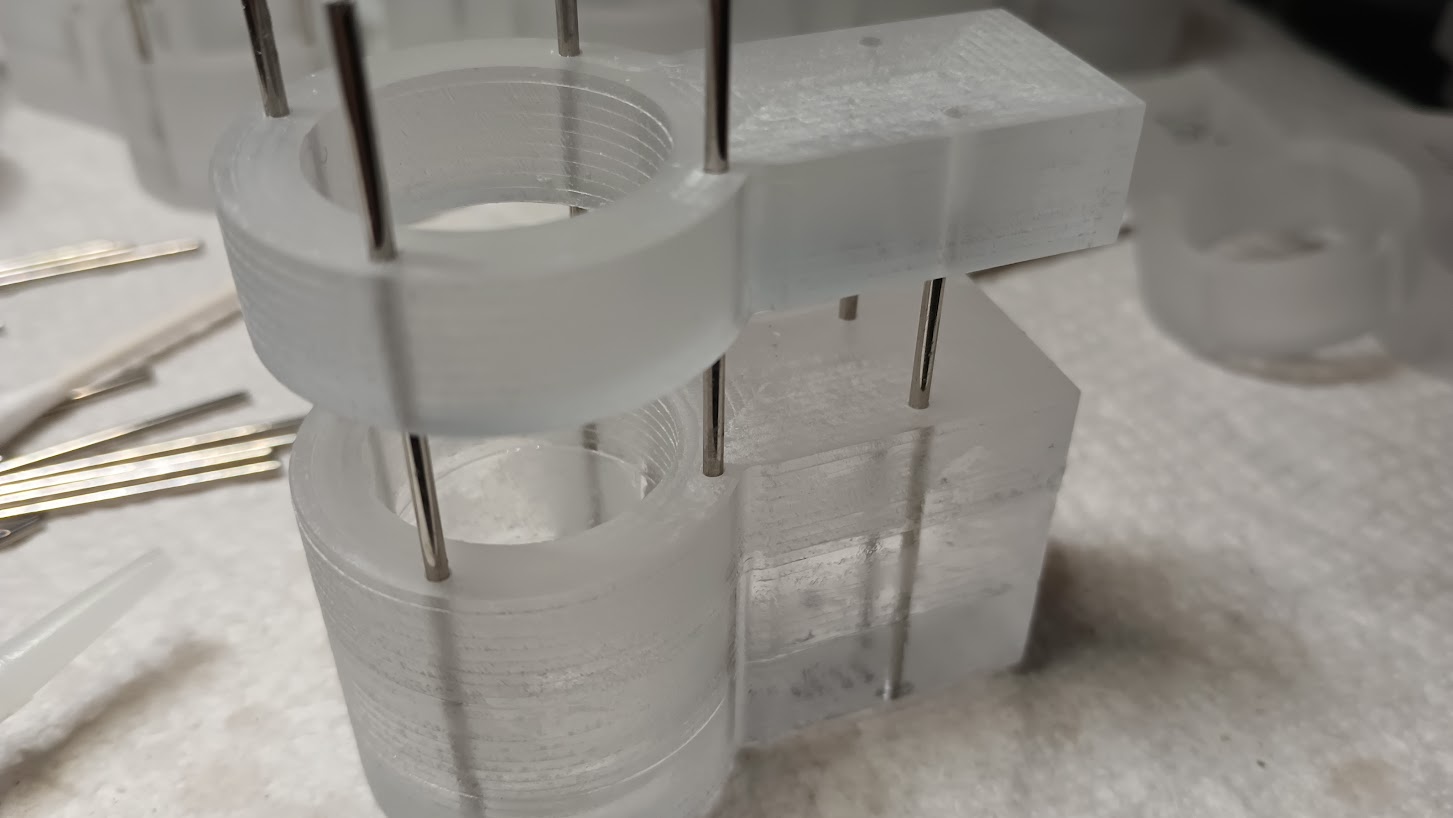
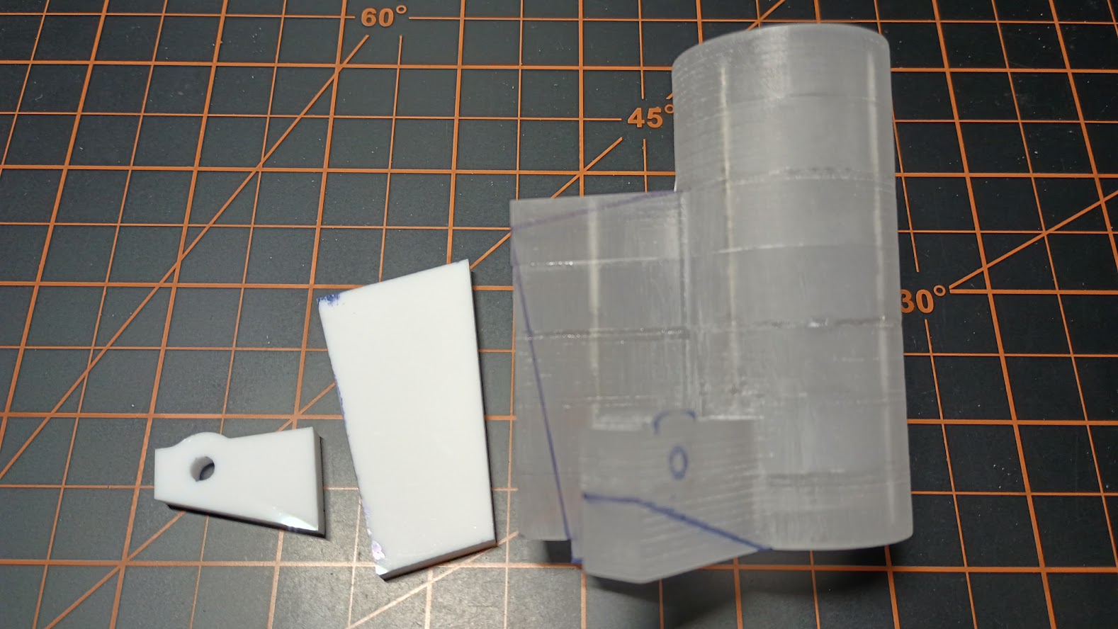
(Original thread started on 10-08-09 by Shane Barnes) What triggers the "stick shaker" in a joystick? I know when I first started FS a few years ago I used a joystick and it would react to stall situations. I know if you look in the cfg file there is something close to the end in the force feedback section and stall warning section. Just don't know how to interface to it. Would this not act like an input such as an LED if we wanted it to light when condition met? Anyone have any knowledge on how to make our stick shakers operate? Here is a wiring diagram example of a set of stick shakers in a sim: FOR ILLUSTRATION PURPOSES ONLY! (Posted by Ron Rollo on 10-08-09) Thanks Shane for starting this thread. The only thing that I am not 100% clear on is how do we interface with MSFS to tell the electric motors when the aircraft is approaching a stall condition and to start shaking. Here is a picture of the copilot's stick shaker in the L45: (Posted by Mark L. on 10-08-09) By watching offset 036C which is the stall warning. Now the question is, is it to late when this offset goes from 0 to 1, or is that when the system alerts that you are about to stall? Testing I guess would prove the outcome. (Posted by DonnyRay Jones on 10-09-09) Monitor the AOA variable. When it crosses a certain threshold which signifies the onset of a stall, spin the stick shaker. This is easy to do externally if you are already driving a real AOA gauge. The real AOA gauge requires a small dc current, which you can monitor with a comparator IC. The comparator output will drive (through the proper circuitry) the motor in the stick shaker. Be aware that this method is not *entirely* aerodynamically correct, but it is pretty easy to implement and is pretty good for the limited amount of modeling that MSFS performs. An AOA system cannot detect the onset of all kinds of stalls, particularly if the aircraft is performing some high-angle or unusual maneuver. But for our purposes here monitoring the AOA variable will cover most cases. A source of motors which may be useful for stick shakers is at: http://www.goldmine-elec-products.com/products.asp?dept=1107 Another source of cheap motors useful for making stick shakers: http://www.allelectronics.com/make-a-store/item/DCM-344/VIBRATOR-MOTOR/1.html These are tiny vibrator motors used in pagers and cell phones, but they are cheeeeeeeeep enough that you can use three of them in a bundle to get more "shaking". Not as powerful as the real deal, but remember, we don't have the same stick forces to contend with in our sims. I'm using three on each control column and they work well for me. Another method of making a larger shaker is to use a simple Adel clamp on the shaft of whatever motor you choose. The Adel clamp has a hole in it which makes it very easy to fasten a weight of your choosing to the shaft. We're talking "Lazy Boy Vibrator Chair" here but if that's what you want that's the easy way to make it. (Posted by Ron Rollo on 05-13-12) I picked up a couple stick shakers on eBay a year ago. They are dated 1961 and came out of a helicopter. They are also 27volt which is common in most aircraft so the challenge will be getting them to work on a 12 volt system and to operate when the aircraft goes into or is approaching a stall condition: (Posted by Eric Tomlin on 05-23-12) Yes, you can get stick shakers to work in FS as there is a Stall Warning offset 036C. Remember, if there's an offset for an item, we can almost always get data out of the sim to activate hardware. Thankfully, there's not a whole lot that we can not get to work in a sim. Some things are useless to some folks, but for the 'core' builder, things like this are great added items. However, don't go getting a call from the virtual FAA about doing unauthorized stall tests in the LJ45. (Posted by Shane Barnes on 05-23-12) I have tried the stick shakers that I have that call for 27vdc with 12v and they do not function with 12v. I plan on getting a 24vdc power supply and seeing if that will work . . according to DonnyRay they should work with 24vdc power supply. I will update once I get the power supply unless someone beats me to it! (Posted by Ron Rollo on 05-23-12) I tested mine and they [b]DO[/b] work with 12 volt power. However, I can tell that it is working with voltage lower than it would like. My stick shakers were built back in the early 60's. They are dated AUG 31 1961. I plan to paint them black and build a bracket for them to attach to the columns. Even with only 12 volts of power, the shack the mess out of themselves! And remember the fact, a normal flight, flying within the envelope, will never trigger the stall system. So unless you wanna show it off to your friends, it is another nice to have but never used feature. But it is cool! (Posted by Eric Tomlin on 05-24-12) Another point- The System Test Panel has a position to test the STALL system and once a certain sequence has been completed, the Stick Shakers will be activated momentarily. So, it will be nice to "test" them and have them move even when not flying if you choose to install them. (Posted by Alan Norris on 05-24-12) Ron, that is interesting that you got yours to work but Shane couldn't. Shane, do you think yours were faulty or maybe a different make? (Posted by Shane Barnes on 05-24-12) Hey Alan, they are not faulty . . they are a different style than Ron's. The ones that I have are out of a Lear 25 or 35. I have had the tops off and the motor moves the weight that is offset to produce the shaking but it is very slow . . 12v is not enough to produce the shake. If I remove the weight then the shaft will rotate at a higher speed . . so it comes down to not enough power to spin the weight. Most likely just a difference in design. I have ordered a 24v power supply so in a few days I should know whether that is the issue. (Posted by Alan Norris on 05-24-12) I've asked the guy selling the stick shakers on eBay to test them to see if they work on 12VDC. Will let you know what he says. Having said that, you can buy 12VDC motors with eccentric weights for about $10 that may do the same job. Ron, any idea what model number yours are so I can ensure I order one that will work on 12v? (Posted by Ron Rollo on 05-30-12) Hey Alan, here is the information you were asking for: Looks like model number 0-71602. I wonder if the others that we have our hands on would work if full 28 volts was applied to them..... (Posted by Shane Barnes on 06-28-12) I have the 27v version and am powering them with 24v. If someone does buy a stick shaker and it does not work try removing the cap that covers the counterweight and try turning the counterweight. One of mine would not operate until I removed the cover and turned the counterweight a couple of times. My thoughts it that the stick shaker had sat for a period of time and some light corrosion had developed on the shaft . . just enough that it would not spin with power applied. (Original thread started on 10-08-09 by Shane Barnes) What triggers the "stick shaker" in a joystick? I know when I first started FS a few years ago I used a joystick and it would react to stall situations. I know if you look in the cfg file there is something close to the end in the force feedback section and stall warning section. Just don't know how to interface to it. Would this not act like an input such as an LED if we wanted it to light when condition met? Anyone have any knowledge on how to make our stick shakers operate? Here is a wiring diagram example of a set of stick shakers in a sim: FOR ILLUSTRATION PURPOSES ONLY! (Posted by Ron Rollo on 10-08-09) Thanks Shane for starting this thread. The only thing that I am not 100% clear on is how do we interface with MSFS to tell the electric motors when the aircraft is approaching a stall condition and to start shaking. Here is a picture of the copilot's stick shaker in the L45: (Posted by Mark L. on 10-08-09) By watching offset 036C which is the stall warning. Now the question is, is it to late when this offset goes from 0 to 1, or is that when the system alerts that you are about to stall? Testing I guess would prove the outcome. (Posted by DonnyRay Jones on 10-09-09) Monitor the AOA variable. When it crosses a certain threshold which signifies the onset of a stall, spin the stick shaker. This is easy to do externally if you are already driving a real AOA gauge. The real AOA gauge requires a small dc current, which you can monitor with a comparator IC. The comparator output will drive (through the proper circuitry) the motor in the stick shaker. Be aware that this method is not *entirely* aerodynamically correct, but it is pretty easy to implement and is pretty good for the limited amount of modeling that MSFS performs. An AOA system cannot detect the onset of all kinds of stalls, particularly if the aircraft is performing some high-angle or unusual maneuver. But for our purposes here monitoring the AOA variable will cover most cases. A source of motors which may be useful for stick shakers is at: http://www.goldmine-elec-products.com/products.asp?dept=1107 Another source of cheap motors useful for making stick shakers: http://www.allelectronics.com/make-a-store/item/DCM-344/VIBRATOR-MOTOR/1.html These are tiny vibrator motors used in pagers and cell phones, but they are cheeeeeeeeep enough that you can use three of them in a bundle to get more "shaking". Not as powerful as the real deal, but remember, we don't have the same stick forces to contend with in our sims. I'm using three on each control column and they work well for me. Another method of making a larger shaker is to use a simple Adel clamp on the shaft of whatever motor you choose. The Adel clamp has a hole in it which makes it very easy to fasten a weight of your choosing to the shaft. We're talking "Lazy Boy Vibrator Chair" here but if that's what you want that's the easy way to make it. (Posted by Ron Rollo on 05-13-12) I picked up a couple stick shakers on eBay a year ago. They are dated 1961 and came out of a helicopter. They are also 27volt which is common in most aircraft so the challenge will be getting them to work on a 12 volt system and to operate when the aircraft goes into or is approaching a stall condition: (Posted by Eric Tomlin on 05-23-12) Yes, you can get stick shakers to work in FS as there is a Stall Warning offset 036C. Remember, if there's an offset for an item, we can almost always get data out of the sim to activate hardware. Thankfully, there's not a whole lot that we can not get to work in a sim. Some things are useless to some folks, but for the 'core' builder, things like this are great added items. However, don't go getting a call from the virtual FAA about doing unauthorized stall tests in the LJ45. (Posted by Shane Barnes on 05-23-12) I have tried the stick shakers that I have that call for 27vdc with 12v and they do not function with 12v. I plan on getting a 24vdc power supply and seeing if that will work . . according to DonnyRay they should work with 24vdc power supply. I will update once I get the power supply unless someone beats me to it! (Posted by Ron Rollo on 05-23-12) I tested mine and they [b]DO[/b] work with 12 volt power. However, I can tell that it is working with voltage lower than it would like. My stick shakers were built back in the early 60's. They are dated AUG 31 1961. I plan to paint them black and build a bracket for them to attach to the columns. Even with only 12 volts of power, the shack the mess out of themselves! And remember the fact, a normal flight, flying within the envelope, will never trigger the stall system. So unless you wanna show it off to your friends, it is another nice to have but never used feature. But it is cool! (Posted by Eric Tomlin on 05-24-12) Another point- The System Test Panel has a position to test the STALL system and once a certain sequence has been completed, the Stick Shakers will be activated momentarily. So, it will be nice to "test" them and have them move even when not flying if you choose to install them. (Posted by Alan Norris on 05-24-12) Ron, that is interesting that you got yours to work but Shane couldn't. Shane, do you think yours were faulty or maybe a different make? (Posted by Shane Barnes on 05-24-12) Hey Alan, they are not faulty . . they are a different style than Ron's. The ones that I have are out of a Lear 25 or 35. I have had the tops off and the motor moves the weight that is offset to produce the shaking but it is very slow . . 12v is not enough to produce the shake. If I remove the weight then the shaft will rotate at a higher speed . . so it comes down to not enough power to spin the weight. Most likely just a difference in design. I have ordered a 24v power supply so in a few days I should know whether that is the issue. (Posted by Alan Norris on 05-24-12) I've asked the guy selling the stick shakers on eBay to test them to see if they work on 12VDC. Will let you know what he says. Having said that, you can buy 12VDC motors with eccentric weights for about $10 that may do the same job. Ron, any idea what model number yours are so I can ensure I order one that will work on 12v? (Posted by Ron Rollo on 05-30-12) Hey Alan, here is the information you were asking for: Looks like model number 0-71602. I wonder if the others that we have our hands on would work if full 28 volts was applied to them..... (Posted by Shane Barnes on 06-28-12) I have the 27v version and am powering them with 24v. If someone does buy a stick shaker and it does not work try removing the cap that covers the counterweight and try turning the counterweight. One of mine would not operate until I removed the cover and turned the counterweight a couple of times. My thoughts it that the stick shaker had sat for a period of time and some light corrosion had developed on the shaft . . just enough that it would not spin with power applied. Hey guys, It has been a while since any of us have talked about the Stick Shakers. In our early days, the quick solution was to pick up a pair of REAL stick shakers and simply install them in our projects. However, there are a couple problems with this solution: If you can find a set that meets all these requirements, congratulations, you would be the first! The real matching set that I was able to obtain several years ago "look" close to what you would find in the Lear45 and were a couple hundred dollars. The problem is they operate on 27.5v. We are building our sims to operate on a 12v system. In order to use these stick shakers, you would have two options: As an example, I opted to run my real set on 12v power and let them run sluggishly while Shane opted to run his set off of a 24v power supply. Neither solution was 100%. This is our dilemma in a nut shell, not to mention the EMI issues stick shakers can cause. So maybe the solution is to develop replica stick shakers? First, we have to know what we are modeling. Here are a couple photos of the real deal in the Lear45. Believe it or not, these are the best photos we have of the stick shakers in the Lear45. Thankfully, DonnyRay was able to supply me with a drawing with a few basic dimensions. This in conjunction with the real set I have on hand was more than enough information to put together a decent plan and drawing. Jason is credited for getting me started on this project! He asked me to take one of mine apart to see how it operates. It is actually a pretty cool design. An electric motor is mounted on the side of the axial shaft and spins a gear in the top ring. On this ring a heavy weight is mounted on one side which makes the ring wobble out of balance. When the stick shaker is activated, the motor spins the gear in the top ring with the weight mounted to it causing an imbalance. By design, the stick shaker acts as if it is coming apart, shaking and make a heck of a racket....and that's the idea after all, to get the pilot's attention. These photos will help illustrate how they are designed and work. Again, these are 27.5v shakers. Another quick thought, these devices go by a couple different names: This is good information to know if you are doing a www search for them. Now that you have a good idea of WHAT we are trying to model, the next question is HOW to model them. As you know, the real units are made of metal and most of us are limited in tools, especially metal fabricating tools. Therefore, I opted to make this version of replica stick shakers using "stacked" cast plastic via the cnc machine. However, this could potentially be a good project to take on with a 3D printer. But even if I had a 3D printer, I might still opt to use the cnc because if there was ever a project that needs to be as solid as possible, it's the Stick Shakers. In other words, it might be faster and result in a stronger bond to cut cast plastic and stack it up rather than build up a single piece via a 3D printer with a spool of plastic filament. If using a 3D printer, I would not recommend taking shortcuts and making hollow areas in the design to save time. Another area that I opted to do differently was to move the 12v motor to the center axial shaft and turn the top third of the center axial shaft into an offset spinner that looks like the real thing. In other words, this design will look like the real thing and operate on 12v. Based on early testing of this design, it will also sound like the real thing and shake around so much that it will be hard to tell that it's not the ring doing the shaking! I also had to change the way the stick shakers mount to the control columns, but they will look the same as the real thing. Basically, because I am building them using cast plastic, I have the ability to group the center axial shaft and the mounting bracket together in one piece of plastic. This will actually make the stick shakers stronger and easier to build. And that brings us to today....... Today I just finished cutting out all the pieces to complete three sets of stick shakers. Most of the parts needed are pictured here. In all, there will be no less than 110 parts in each unit believe it or not. Now for the fun part......assembly. As I proceed forward, I will include photos in a tutorial so that anyone can take on this project as long as you have a cnc machine. Also feel free to take the attached dxf and convert it to make 3D files to be cut with a 3D printer. This would be interesting to see. If this works as well as I expect it will, this solves the problems pointed out at the top of this post. I will have an update on this project shortly! Hey guys, It has been a while since any of us have talked about the Stick Shakers. In our early days, the quick solution was to pick up a pair of REAL stick shakers and simply install them in our projects. However, there are a couple problems with this solution: If you can find a set that meets all these requirements, congratulations, you would be the first! The real matching set that I was able to obtain several years ago "look" close to what you would find in the Lear45 and were a couple hundred dollars. The problem is they operate on 27.5v. We are building our sims to operate on a 12v system. In order to use these stick shakers, you would have two options: As an example, I opted to run my real set on 12v power and let them run sluggishly while Shane opted to run his set off of a 24v power supply. Neither solution was 100%. This is our dilemma in a nut shell, not to mention the EMI issues stick shakers can cause. So maybe the solution is to develop replica stick shakers? First, we have to know what we are modeling. Here are a couple photos of the real deal in the Lear45. Believe it or not, these are the best photos we have of the stick shakers in the Lear45. Thankfully, DonnyRay was able to supply me with a drawing with a few basic dimensions. This in conjunction with the real set I have on hand was more than enough information to put together a decent plan and drawing. Jason is credited for getting me started on this project! He asked me to take one of mine apart to see how it operates. It is actually a pretty cool design. An electric motor is mounted on the side of the axial shaft and spins a gear in the top ring. On this ring a heavy weight is mounted on one side which makes the ring wobble out of balance. When the stick shaker is activated, the motor spins the gear in the top ring with the weight mounted to it causing an imbalance. By design, the stick shaker acts as if it is coming apart, shaking and make a heck of a racket....and that's the idea after all, to get the pilot's attention. These photos will help illustrate how they are designed and work. Again, these are 27.5v shakers. Another quick thought, these devices go by a couple different names: This is good information to know if you are doing a www search for them. Now that you have a good idea of WHAT we are trying to model, the next question is HOW to model them. As you know, the real units are made of metal and most of us are limited in tools, especially metal fabricating tools. Therefore, I opted to make this version of replica stick shakers using "stacked" cast plastic via the cnc machine. However, this could potentially be a good project to take on with a 3D printer. But even if I had a 3D printer, I might still opt to use the cnc because if there was ever a project that needs to be as solid as possible, it's the Stick Shakers. In other words, it might be faster and result in a stronger bond to cut cast plastic and stack it up rather than build up a single piece via a 3D printer with a spool of plastic filament. If using a 3D printer, I would not recommend taking shortcuts and making hollow areas in the design to save time. Another area that I opted to do differently was to move the 12v motor to the center axial shaft and turn the top third of the center axial shaft into an offset spinner that looks like the real thing. In other words, this design will look like the real thing and operate on 12v. Based on early testing of this design, it will also sound like the real thing and shake around so much that it will be hard to tell that it's not the ring doing the shaking! I also had to change the way the stick shakers mount to the control columns, but they will look the same as the real thing. Basically, because I am building them using cast plastic, I have the ability to group the center axial shaft and the mounting bracket together in one piece of plastic. This will actually make the stick shakers stronger and easier to build. And that brings us to today....... Today I just finished cutting out all the pieces to complete three sets of stick shakers. Most of the parts needed are pictured here. In all, there will be no less than 110 parts in each unit believe it or not. Now for the fun part......assembly. As I proceed forward, I will include photos in a tutorial so that anyone can take on this project as long as you have a cnc machine. Also feel free to take the attached dxf and convert it to make 3D files to be cut with a 3D printer. This would be interesting to see. If this works as well as I expect it will, this solves the problems pointed out at the top of this post. I will have an update on this project shortly! Hey guys, I've been busy working on the stick shakers! This past week it has been all about building up the main pieces from a bunch of smaller pieces. This is one of the only projects that I have taken on that is more three dimensional than flat, as an example the backlit panels. Therefor, I have had to come up with new procedures (new to me anyway) and methods to achieve my goals. As I mentioned in the previous post, I opted to move forward with making these parts with the CNC machine to take advantage of the heavier and stronger cast plastic. Most of the pieces that make up larger parts are made of .5" clear cast plastic. The dense cast plastic when bonded properly will result in stronger and heavier parts. I designed all the larger parts to include "rebar"..........actually 1/16" steel rods. This helps greatly with the alignment process during bonding and adds incredible strength. As you know, when using "Super Glue", it sets within a couple seconds so when you put the two pieces together, make sure they are exactly where you want them because rarely will you get them apart without causing damage. I started off with the easier and smaller parts first. This first piece is what I call the top spinner. It mounts to the 12v motor shaft and spins at 6,000 RPM. Actually, once the strip weights are added, the RPMs will drop slightly. (Keep in mind this is not how the real stack shakers are designed. This is a unique way to achieve our goals while looking the part!) This next piece is what I call the Top Arm Trim. The design calls for this piece to be .75" thick and I don't have easy access to .75" thick plastic, let alone the endmill bits to cut plastic that deep. So the work around solution is to bond two .35" pieces together. Here is the Ring Cap assembly where there are three pieces to this part. Notice the steel rods that help with alignment and strength. Next is the Axial Shaker stack. This piece is made up of eight parts in total, not including the steel rods. During the CNC process, I took the time to measure the thickness of all the parts. My concern was that being there are eight parts making up the final piece, my luck is I would have all the thicker parts stacked together to make up one piece and all the thinner parts stacked up to make up another piece. Hundredths of an inch here or there in this case is not a big deal but add them up and then we would be talking 16ths of an inch here or there! This process insures all assembled parts are within a hundredth of an inch of one another. In other words, the Cpt side parts won't be noticeably different in size compared to the FO side parts. The steel rods work great to help keep things lined up properly during the bonding process! Once the Axial Shaker stack is built up, there is one last step that needs to be completed. I made marking jigs to properly mark where some of the material still needs to be removed from the brackets that branch out off the sides to create their final shape. Later on in this tutorial I will cover the trimming and shaving processes. This next set of parts make up the Side Arm. The same process of using the steel rods is used here as the previous parts, everything lines up perfectly. Sanding, filling and paint will be much easier. "You gotta have some skin in the game!" If you have any experience using "Super Glue", you know how fast it sets and how easy it is to glue your fingers to your work. And with all the bonding needed to be done working with these six sets of stick shaker parts, I don't have enough skin on my fingers! The solution here is to protect the tips of your fingers with a little painters tape. I have had my fingers wrapped for the whole bonding process and so far, so good! I opted to use painter tape on my fingertips over Latex gloves because in my experience, once you get a little glue on the gloves, they rip open. The painters tape allowed me to get through a complete set of parts without needing to replace them. Another important step is tapping out the screw holes. Most of the screw holes are 4-40 size. The screw holes in the Ring Cap are 2-56. Tapping into plastic is fairly easy with a hand tap tool and as long as your starter holes are the correct size, there will be no issues. Here I am about half way through the process of tapping the Side Arm holes. This is another one of those areas where I am insuring that all the final parts are within a hundredth of an inch of one another in an effort to avoid issues later on. This process takes a few extra minutes to sort out but well worth the time. And this is the last set of pieces that require bonding. Because I have an aluminum bracket built into the design to add strength to the bottom end of the Side Arms, I did not need to run the steel rods down into this piece. Two screws will hold the aluminum bracket in place and screw up into both bonded pieces. However, I still needed a way to insure alignment of the two pieces being bonded. In this case, I used the shaft ends of two 7/64" drill bits. Here is a complete set of parts that will help make up one unit. And just to show the full scope of the project I have on my hands, here is a photo of all the parts for six units. (three sets) It's a lot of work but I am very excited seeing how well they are all coming along! At this point, 90% of the "dirty work" is complete. Cutting out the parts with the CNC machine, bonding all the parts together and rough sanding to insure the parts are lined up properly. The next steps coming up will be making the aluminum bottom brackets, column mounting plates, shaving the Axial Shaker pieces and a few other odds and ends. Another update shortly! Hey guys, I've been busy working on the stick shakers! This past week it has been all about building up the main pieces from a bunch of smaller pieces. This is one of the only projects that I have taken on that is more three dimensional than flat, as an example the backlit panels. Therefor, I have had to come up with new procedures (new to me anyway) and methods to achieve my goals. As I mentioned in the previous post, I opted to move forward with making these parts with the CNC machine to take advantage of the heavier and stronger cast plastic. Most of the pieces that make up larger parts are made of .5" clear cast plastic. The dense cast plastic when bonded properly will result in stronger and heavier parts. I designed all the larger parts to include "rebar"..........actually 1/16" steel rods. This helps greatly with the alignment process during bonding and adds incredible strength. As you know, when using "Super Glue", it sets within a couple seconds so when you put the two pieces together, make sure they are exactly where you want them because rarely will you get them apart without causing damage. I started off with the easier and smaller parts first. This first piece is what I call the top spinner. It mounts to the 12v motor shaft and spins at 6,000 RPM. Actually, once the strip weights are added, the RPMs will drop slightly. (Keep in mind this is not how the real stack shakers are designed. This is a unique way to achieve our goals while looking the part!) This next piece is what I call the Top Arm Trim. The design calls for this piece to be .75" thick and I don't have easy access to .75" thick plastic, let alone the endmill bits to cut plastic that deep. So the work around solution is to bond two .35" pieces together. Here is the Ring Cap assembly where there are three pieces to this part. Notice the steel rods that help with alignment and strength. Next is the Axial Shaker stack. This piece is made up of eight parts in total, not including the steel rods. During the CNC process, I took the time to measure the thickness of all the parts. My concern was that being there are eight parts making up the final piece, my luck is I would have all the thicker parts stacked together to make up one piece and all the thinner parts stacked up to make up another piece. Hundredths of an inch here or there in this case is not a big deal but add them up and then we would be talking 16ths of an inch here or there! This process insures all assembled parts are within a hundredth of an inch of one another. In other words, the Cpt side parts won't be noticeably different in size compared to the FO side parts. The steel rods work great to help keep things lined up properly during the bonding process! Once the Axial Shaker stack is built up, there is one last step that needs to be completed. I made marking jigs to properly mark where some of the material still needs to be removed from the brackets that branch out off the sides to create their final shape. Later on in this tutorial I will cover the trimming and shaving processes. This next set of parts make up the Side Arm. The same process of using the steel rods is used here as the previous parts, everything lines up perfectly. Sanding, filling and paint will be much easier. "You gotta have some skin in the game!" If you have any experience using "Super Glue", you know how fast it sets and how easy it is to glue your fingers to your work. And with all the bonding needed to be done working with these six sets of stick shaker parts, I don't have enough skin on my fingers! The solution here is to protect the tips of your fingers with a little painters tape. I have had my fingers wrapped for the whole bonding process and so far, so good! I opted to use painter tape on my fingertips over Latex gloves because in my experience, once you get a little glue on the gloves, they rip open. The painters tape allowed me to get through a complete set of parts without needing to replace them. Another important step is tapping out the screw holes. Most of the screw holes are 4-40 size. The screw holes in the Ring Cap are 2-56. Tapping into plastic is fairly easy with a hand tap tool and as long as your starter holes are the correct size, there will be no issues. Here I am about half way through the process of tapping the Side Arm holes. This is another one of those areas where I am insuring that all the final parts are within a hundredth of an inch of one another in an effort to avoid issues later on. This process takes a few extra minutes to sort out but well worth the time. And this is the last set of pieces that require bonding. Because I have an aluminum bracket built into the design to add strength to the bottom end of the Side Arms, I did not need to run the steel rods down into this piece. Two screws will hold the aluminum bracket in place and screw up into both bonded pieces. However, I still needed a way to insure alignment of the two pieces being bonded. In this case, I used the shaft ends of two 7/64" drill bits. Here is a complete set of parts that will help make up one unit. And just to show the full scope of the project I have on my hands, here is a photo of all the parts for six units. (three sets) It's a lot of work but I am very excited seeing how well they are all coming along! At this point, 90% of the "dirty work" is complete. Cutting out the parts with the CNC machine, bonding all the parts together and rough sanding to insure the parts are lined up properly. The next steps coming up will be making the aluminum bottom brackets, column mounting plates, shaving the Axial Shaker pieces and a few other odds and ends. Another update shortly! Column Stick Shaker Discussion
![]()
![]()
![]()
2017-10-10