


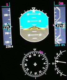
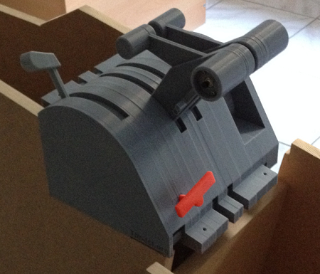
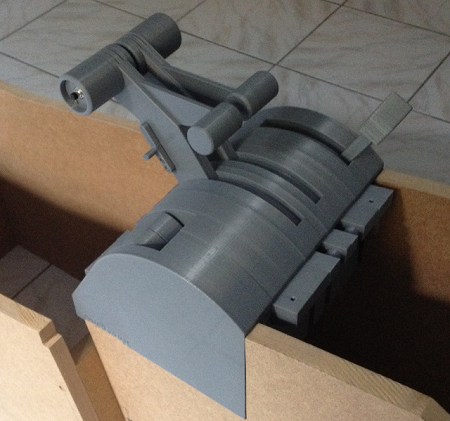
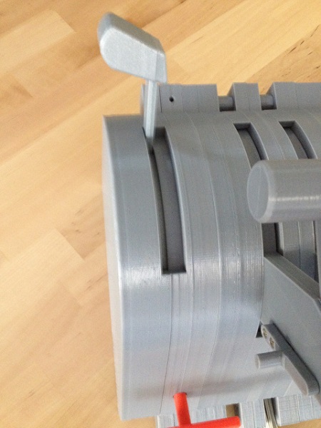
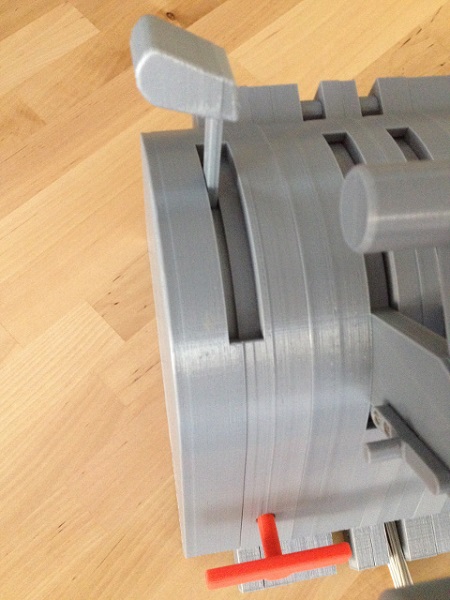
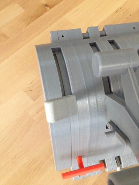
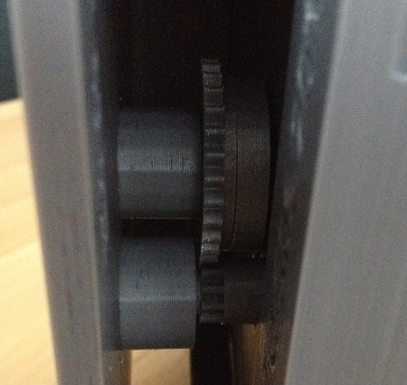
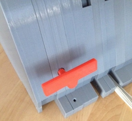
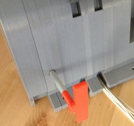
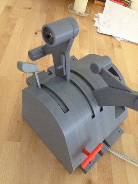
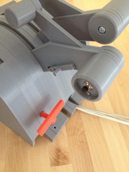
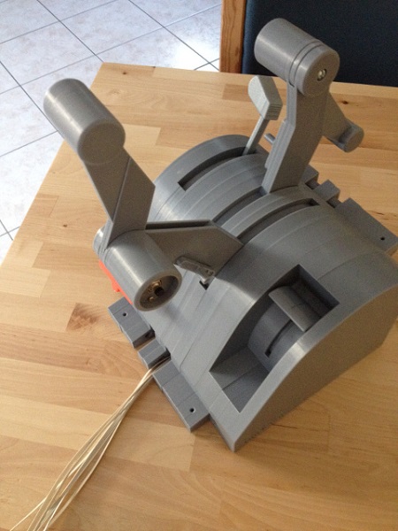
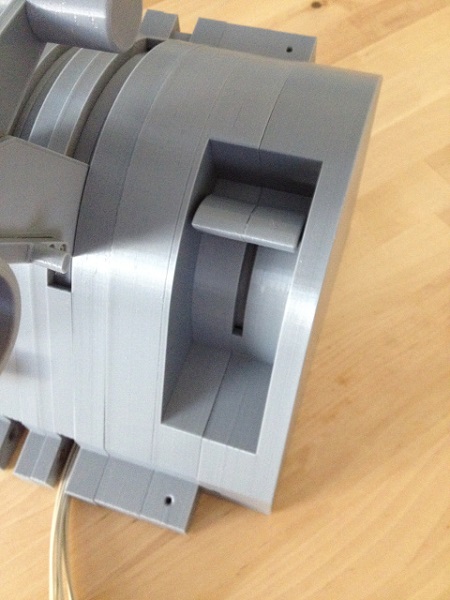
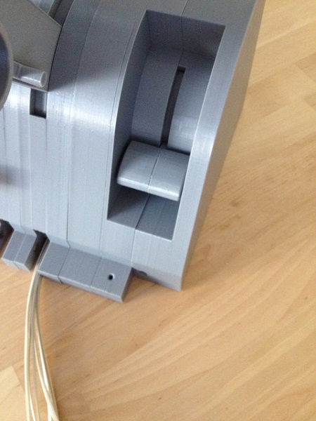
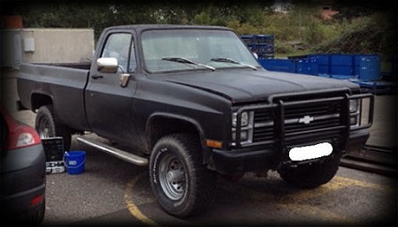
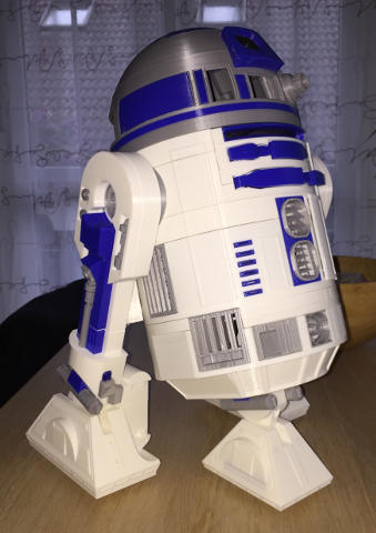
(Original thread started on 07-12-14 by Tim) My name is Tim, I'm from Germany and I've been working on a Lear 45 home cockpit for a few years now. Since I'm a software guy I've started with pulling data from FSX, FlightGear or X-Plane and displaying it on a PFD / EICAS application: But I soon noticed that you need a bit more of a hardware setup before you can enjoy refining the software, so I started working on some panels. This endeavor showed me that my hands are better suited to work a keyboard than jigsaws and drills. So now I'm designing parts with OpenSCAD and have my RepRap 3D printer build them for me. The most complex thing I've built so far is the throttle quadrant: I know that some of you guys produce much better parts with backlighting and everything, and that there's already a complete avionics software pack available - but, for me, the fun is in designing this stuff... If you'd like to take a closer look at the TQ, you can find it here: http://timjet.org/node/24]TQ Development (Posted by Ron Rollo on 07-12-14) Hi Tim, glad you found us! Wow, you have some pretty serious skills there in CAD and 3D printing. You started with the most complicated part of the aircraft. Now what are you going to do for fun? LOL I saw the photos to your link and they are very impressive. How realistic are they and do all the functions work on them? (Posted by Timaios on 07-12-14) Thanks! I guessed it was the most complicated part, so I thought if the printer could do that, it could do the rest as well. To answer your questions, I have take some photos. 1) Spoilers lever: The lever is spring-loaded, you need to pull it up to move it: Spoilers in the "ARMED" position: Spoilers in the "DEPLOYED" position: The lever's base has teeth which drive another gear, and that one moves the connected pot: 2) Parking brake: You can pull the handle (about 50mm) and rotate it clock-wise to lock it. There's a sensor/switch inside which closes a circuit if the brake handle is NOT pulled: The parking brake is set: (Original thread started on 07-12-14 by Tim) My name is Tim, I'm from Germany and I've been working on a Lear 45 home cockpit for a few years now. Since I'm a software guy I've started with pulling data from FSX, FlightGear or X-Plane and displaying it on a PFD / EICAS application: But I soon noticed that you need a bit more of a hardware setup before you can enjoy refining the software, so I started working on some panels. This endeavor showed me that my hands are better suited to work a keyboard than jigsaws and drills. So now I'm designing parts with OpenSCAD and have my RepRap 3D printer build them for me. The most complex thing I've built so far is the throttle quadrant: I know that some of you guys produce much better parts with backlighting and everything, and that there's already a complete avionics software pack available - but, for me, the fun is in designing this stuff... If you'd like to take a closer look at the TQ, you can find it here: http://timjet.org/node/24%5DTQ Development (Posted by Ron Rollo on 07-12-14) Hi Tim, glad you found us! Wow, you have some pretty serious skills there in CAD and 3D printing. You started with the most complicated part of the aircraft. Now what are you going to do for fun? LOL I saw the photos to your link and they are very impressive. How realistic are they and do all the functions work on them? (Posted by Timaios on 07-12-14) Thanks! I guessed it was the most complicated part, so I thought if the printer could do that, it could do the rest as well. To answer your questions, I have take some photos. 1) Spoilers lever: The lever is spring-loaded, you need to pull it up to move it: Spoilers in the "ARMED" position: Spoilers in the "DEPLOYED" position: The lever's base has teeth which drive another gear, and that one moves the connected pot: 2) Parking brake: You can pull the handle (about 50mm) and rotate it clock-wise to lock it. There's a sensor/switch inside which closes a circuit if the brake handle is NOT pulled: The parking brake is set: 3) Throttle levers: The levers can be moved from idle to APR position. If the small handle on the lever's shaft is drawn (while in the idle position) the lever can be moved further down to the cutoff position. It uses the same mechanics as the spoilers lever (gears driving pots): 4) Reversers: The reversers can be drawn (anytime - I know that's not how they really work...) and trigger a switch inside the throttle lever's grip: 5) Flaps lever: The flaps lever works just like the spoilers lever, but it's got four notches: Flaps in the 40 degrees down position: If you want to take a look at the inside workings of the TQ, you can open the sub pages "Wall Segments", etc. using the links at the bottom of the main page: http://timjet.org/node/24]TQ Development page I haven't created the interface yet, but I've already done a "proof of concept" with a gear lever. The sensors/switches of the lever were read by an ATMEL microcontroller, sent to a Raspberry Pi, send over LAN to an X-Plane plugin which changed the corresponding DataRefs. That gives me some confidence that I'll be able to interface this monster here as well... (Posted by Ron Rollo on 07-12-14) Tim, this is some of the most impressive work I have seen in a long time! I opened up the sub page and wow, that just blows me away! How long would it take to make one of these from start to finish and what kind of cost? As you probably know, we have about 10 sets of the real Lear45 throttles floating around among the Hangar members and several sets built up by Mark L. but we still have guys that are wanting throttle parts. (Posted by Timaios on 07-13-14) Hi Ron, thanks again! As you can image, I've printed and reprinted the parts a few times over the last few months, so I really had no idea how long it had taken me altogether. So, I've just run the various drawings through the slicer software which gives a fairly accurate estimated printing time (even without actually printing the parts). I came up with 130 hours using the default 0.5mm nozzle, and 214 hours using the finer 0.3mm nozzle. Since the printer shouldn't work without someone being in the house, it mostly runs at night (with a smoke detector mounted on the ceiling directly above it). So my guess is, it would take about three weeks to print all the parts for one TQ. The printer could probably do it much faster, but I tend to trade speed for accuracy. There's a lot of potential to speed things up, but it hasn't been an issue yet. As for the cost, I can only say that printing all parts requires about 1.4 kg of raw 3D filament (PLA), which cost me about 40 Euros ($55), but I have no idea how much these hours of printing add to my electricity bill... If someone wanted a printed TQ, I think I would have to put together some kind of kit because some of the design depends heavily on which pots, sensors, etc. are used. But that shouldn't be too hard, because I've been trying to keep the number of non-printed parts (or vitamins, as the 3D nerds call them) down. I've had a look at these drawings a few years ago, after one of my first visits here, but I didn't realize that these were the "real" ones which are used in the Learjet 45. Well, these will help with updating the shape of the throttle lever shafts. I didn't get what you meant by the "indents". Did you refer to the notches that make the levers "snap" to the predefined positions (e.g. 0, 8, 20 and 40 degrees for the flaps lever)? These are already implemented for the speed brake and flaps levers. I just hadn't realized there were also detents for the throttle levers (MCR, MCT, T/O and APR). But like you said, that's something to add in the next iteration. (Posted by Ron Rollo on 07-13-14) Hey Tim, you are correct. You have to pull the side lever up to access the APR indent. (Posted by Ron Rollo on 05-26-17) Hey guys, I just wanted to bump this thread. Tim over in Germany built this incredible TQ using a 3D printer! It is some really cool engineering and if nothing else, we may get some ideas from it. It of course will not fit in our TQ modules without a redesign. This short thread was lost in the "Welcome Center" forum! If anyone wants to take a look at the inside workings of this TQ, you can open the sub pages "Wall Segments", etc. using the links at the bottom of the main HERE: [url=http://timjet.org/node/24]TQ Development page[/url]. (Posted by Tim on 08-16-17) Hi there, it's been a while since my last post on this forum, and I happened to log in again just a few weeks after Ron bumped this thread! I was surprised (sort of) to see that this thread is already three years old! And I have to admit that the project - and the TQ - hasn't come far since then. That's due to the fact that shortly after this post one of my childhood dreams finally came true when I found myself another great American invention, which required me to learn a completely new set of skills: It took me two years to get this little monster street legal. After that, when the 3D printer was about to warm up again, my two boys decided it would be better not to start with the cockpit but to go ahead and build a copilot first. They've got majority vote, so that's what I did: Now that this project's almost complete, I can finally get "back to business" and resume my work on the LJ45. As for the TQ, I'm going to change a few things that I'm not too happy with, such as the missing indents and the fact that the levers move way too easily. While I'm on it, I thought I could also implement the necessary changes to achieve compatibility with the Project45 specs, as that would surely be beneficial to my build and maybe to some other members as well. Could anyone give me a hint where to find these specs and what the critical dimensions are? Greetings from cloudy Germany, Tim (Posted by Ron Rollo on 08-16-17) Hey Tim, good to see you here in the Hangar! Two great looking projects by the way. Look like a full scale 2RD2 replica. A conversation piece for sure. Will it be motorized? 3) Throttle levers: The levers can be moved from idle to APR position. If the small handle on the lever's shaft is drawn (while in the idle position) the lever can be moved further down to the cutoff position. It uses the same mechanics as the spoilers lever (gears driving pots): 4) Reversers: The reversers can be drawn (anytime - I know that's not how they really work...) and trigger a switch inside the throttle lever's grip: 5) Flaps lever: The flaps lever works just like the spoilers lever, but it's got four notches: Flaps in the 40 degrees down position: If you want to take a look at the inside workings of the TQ, you can open the sub pages "Wall Segments", etc. using the links at the bottom of the main page: http://timjet.org/node/24%5DTQ Development page I haven't created the interface yet, but I've already done a "proof of concept" with a gear lever. The sensors/switches of the lever were read by an ATMEL microcontroller, sent to a Raspberry Pi, send over LAN to an X-Plane plugin which changed the corresponding DataRefs. That gives me some confidence that I'll be able to interface this monster here as well... (Posted by Ron Rollo on 07-12-14) Tim, this is some of the most impressive work I have seen in a long time! I opened up the sub page and wow, that just blows me away! How long would it take to make one of these from start to finish and what kind of cost? As you probably know, we have about 10 sets of the real Lear45 throttles floating around among the Hangar members and several sets built up by Mark L. but we still have guys that are wanting throttle parts. (Posted by Timaios on 07-13-14) Hi Ron, thanks again! As you can image, I've printed and reprinted the parts a few times over the last few months, so I really had no idea how long it had taken me altogether. So, I've just run the various drawings through the slicer software which gives a fairly accurate estimated printing time (even without actually printing the parts). I came up with 130 hours using the default 0.5mm nozzle, and 214 hours using the finer 0.3mm nozzle. Since the printer shouldn't work without someone being in the house, it mostly runs at night (with a smoke detector mounted on the ceiling directly above it). So my guess is, it would take about three weeks to print all the parts for one TQ. The printer could probably do it much faster, but I tend to trade speed for accuracy. There's a lot of potential to speed things up, but it hasn't been an issue yet. As for the cost, I can only say that printing all parts requires about 1.4 kg of raw 3D filament (PLA), which cost me about 40 Euros ($55), but I have no idea how much these hours of printing add to my electricity bill... If someone wanted a printed TQ, I think I would have to put together some kind of kit because some of the design depends heavily on which pots, sensors, etc. are used. But that shouldn't be too hard, because I've been trying to keep the number of non-printed parts (or vitamins, as the 3D nerds call them) down. I've had a look at these drawings a few years ago, after one of my first visits here, but I didn't realize that these were the "real" ones which are used in the Learjet 45. Well, these will help with updating the shape of the throttle lever shafts. I didn't get what you meant by the "indents". Did you refer to the notches that make the levers "snap" to the predefined positions (e.g. 0, 8, 20 and 40 degrees for the flaps lever)? These are already implemented for the speed brake and flaps levers. I just hadn't realized there were also detents for the throttle levers (MCR, MCT, T/O and APR). But like you said, that's something to add in the next iteration. (Posted by Ron Rollo on 07-13-14) Hey Tim, you are correct. You have to pull the side lever up to access the APR indent. (Posted by Ron Rollo on 05-26-17) Hey guys, I just wanted to bump this thread. Tim over in Germany built this incredible TQ using a 3D printer! It is some really cool engineering and if nothing else, we may get some ideas from it. It of course will not fit in our TQ modules without a redesign. This short thread was lost in the "Welcome Center" forum! If anyone wants to take a look at the inside workings of this TQ, you can open the sub pages "Wall Segments", etc. using the links at the bottom of the main HERE: [url=http://timjet.org/node/24]TQ Development page[/url]. (Posted by Tim on 08-16-17) Hi there, it's been a while since my last post on this forum, and I happened to log in again just a few weeks after Ron bumped this thread! I was surprised (sort of) to see that this thread is already three years old! And I have to admit that the project - and the TQ - hasn't come far since then. That's due to the fact that shortly after this post one of my childhood dreams finally came true when I found myself another great American invention, which required me to learn a completely new set of skills: It took me two years to get this little monster street legal. After that, when the 3D printer was about to warm up again, my two boys decided it would be better not to start with the cockpit but to go ahead and build a copilot first. They've got majority vote, so that's what I did: Now that this project's almost complete, I can finally get "back to business" and resume my work on the LJ45. As for the TQ, I'm going to change a few things that I'm not too happy with, such as the missing indents and the fact that the levers move way too easily. While I'm on it, I thought I could also implement the necessary changes to achieve compatibility with the Project45 specs, as that would surely be beneficial to my build and maybe to some other members as well. Could anyone give me a hint where to find these specs and what the critical dimensions are? Greetings from cloudy Germany, Tim (Posted by Ron Rollo on 08-16-17) Hey Tim, good to see you here in the Hangar! Two great looking projects by the way. Look like a full scale 2RD2 replica. A conversation piece for sure. Will it be motorized?TQ Module Prototype Using a 3D Printer
![]()
![]()
2017-10-10