


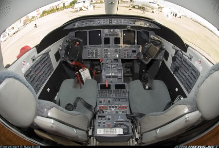
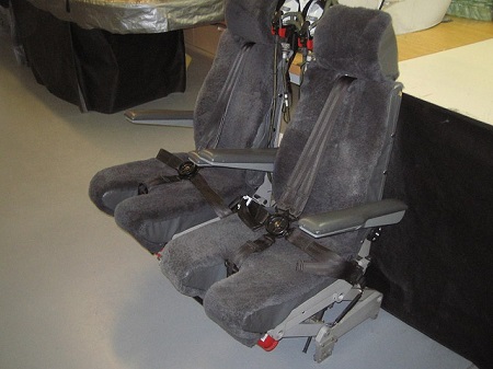
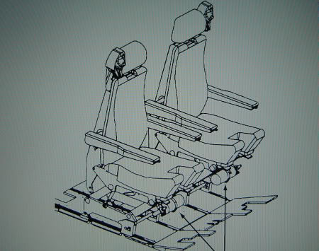
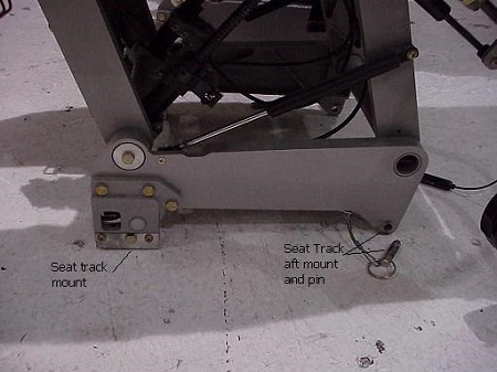
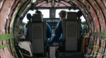
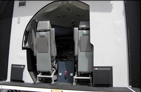
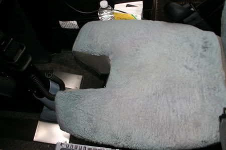
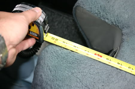
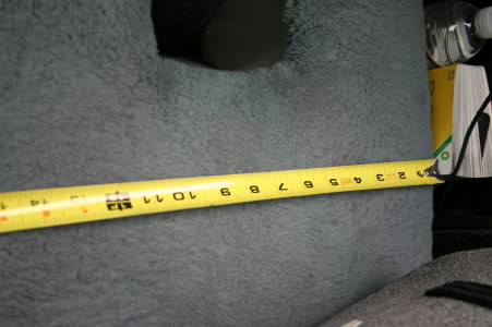
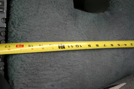
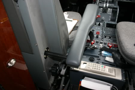
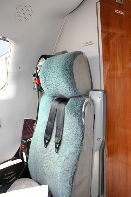
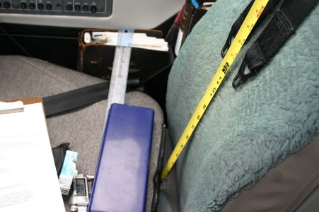
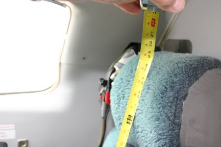
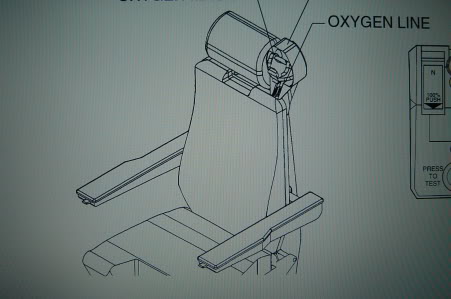
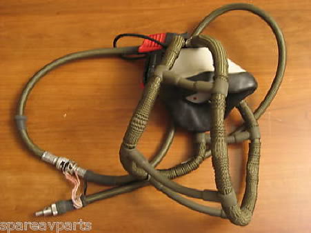
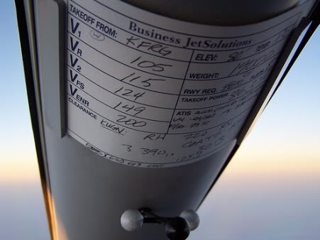
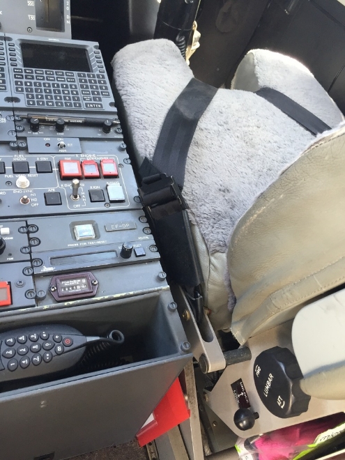
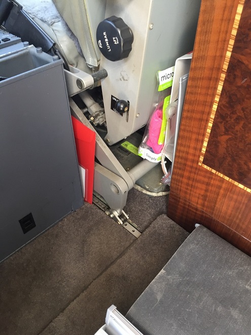
(Original thread started on 04-07-10 by Ron Rollo) If you would like to try to build the crew seats on your own, here is a little information that I found that will help you in the planning stages of the project. If you have additional information or helpful pictures, please post them here! To start with, there are two crew seats! The part number or at least one confirmed part number for the crew seats is TALJ2-Series. There is a left and right, or at least the parts of the seats have to be configured to be a LEFT or a RIGHT seat: NOTE: In this photo above, the Pilot seat is on the right and the Copilot seat is on the left. Take note of the oxygen mask! Starting from the bottom and working our way up, (to the best of my knowledge and with the help of the shell and it's physical limitations), the rail system is 11 inches wide and 24 inches long. If you have or are planning on getting a Project45 shell, make sure you stick to these measurements! The base of the seats are designed to absorb energy in case the copilot has a hard landing. It is sort of like a scissor system. At the front of each of the seats you will find a fire extinguisher: FIRE EXTINGUISHERS Here is a good photo of the lower seat assembly: The seats adjust forward and aft, they tilt at the base to the rear, they adjust up and down to set proper view point and the armrest fold away behind the seat backs: Another great photo of the back side of the seats thanks to this class-D sim: By the way, thanks to Scott Wegner for supplying us with these great photos from his field trip into a Lear45 at his local air field! The seat base is 17 inches wide at it's widest point near the front and narrows as it approaches the rear near the back of the seat. They are approximately 20.5 inches long. I don't need to tell you that they have a column notch at the front just in case you want to pull the columns back into your chest and experience 3 plus "G's" of simulated force! The seat belt system is a five point harness that buckles across the laps of the crew with a shoulder harness and a negative-G strap. Here is a close up of the telescopic armrest mechanism. This has to be done this way so that the crew can gain access to the flight deck. Once seated, the armrest can be pulled out from the stowed position: The back of the seats are 29 inches tall including the head rest: Mounted on the outboard side of each of the headrest is an oxygen storage cup: Here is the actual oxygen mask. From time to time, you can find these on eBay but they end up selling for around $600....EACH! I personally plan to make a couple replicas of these little guys. After all, I am only 15 feet above sea level here in Jacksonville Florida! The headrest is the last part of the seats. I believe that the headrest does extend and adjust upwards but I have not seen any photos of this. To end with, the seats have been a pain trying to find information on them but I do believe that we have enough information to model them satisfactorily. If you have additional information on the L45 seats, please post it here. (Posted by Kurby on 04-08-10) Text from the pilots manual: CREW SEATS The crew seats (Figure 7-2) are comprised of three basic structures: the seat base, the seat bottom and the seat back. The seat base is attached to and travels on the seat tracks. The seat bottom is located above the seat base and provides controls for forward/aft movement, seat height adjustment and seat back reclining adjustment. The seat back contains the lumbar adjustment control, adjustable armrests and an adjustable headrest. The crew seats are constructed of lightweight alloys covered with foam padding and sheepskin and are equipped with a five point restraint system. The lap belts and negative-G strap are mounted to the seat bottom. The rotary buckle is attached to the outboard lap belt. The man-ual lock/unlock handle for the shoulder harness belts is located on the inboard side of the seat back frame. Pilot’s Manual 7-6 PM-126A Seat height adjustment is accomplished by pulling up on the vertical adjustment control lever located under the forward edge of the seat bottom near the outboard side of the seat. When the lever is pulled, the mechanism is unlocked and the seat will move downward under the occupant’s weight. To raise the seat, remove occupant weight from the seat while pulling up on the lever. Gas cylinders will cause the seat to automatically raise up. Release the lever at the desired height to lock the seat into place. Forward and aft adjustment of the seat is accomplished by pulling up on the fore/aft adjustment control lever located under the forward edge of the seat bottom near the inboard side of the seat. The seat can be moved by holding the control lever up, and at the same time, sliding the seat forward or aft on the seat tracks. When the desired position is obtained, the control lever can be released to lock the seat to the seat track. The headrest may be adjusted for both angle and height. The headrest can be tilted forward to an angle of up to 60° by tilting it by hand. The headrest can also be raised up to 2 inches by lifting the headrest. The headrest can be lowered by pushing it down to the desired height. The back cushion/lumbar support is controlled by turning the fore/aft lumbar adjustment control handwheel located on the inboard side of the seat back frame. Turning the handwheel counterclockwise (as viewed looking outboard) extends the lumbar support forward. Turning the handwheel clockwise will retract the lumbar support. The armrests are individually stowable and adjustable. Each armrest has an adjusting wheel on the underside of the armrest. To deploy the armrest, slide the armrest out from the seat back and rotate it down into position. To raise and lower the armrest position, turn the adjusting wheel on the underside of the armrest. The armrests will adjust 15 to 26°. To stow the armrests for entry and exit, lift the armrest until it is parallel with the seat back and push it in toward the seat spine. The seat back recline angle is adjustable. The recline adjustment control lever is located on the outboard side of the crew seat bottom. Pull up on the recline control lever to release the seat back lock and lean the seat to the desired angle. The seat back can be reclined 25°. The seat back will lock in the selected position when the control lever is released." (Posted by Ron Rollo on 09-20-11) There are two keys to know if you are at the proper seat height in the Lear45. First is this three ball system on the center post between the left and right windscreens. You want to have the three balls in a perfect horizontal line. In the case in this photo, the pilot would have his seat set too high: Because your not going to have a center post or a tri-ball system, the second way to know if your seat height is correct is looking at the under side of the aluminum glare shield. If you can see the under side of the glare shield your too low. Adjust your seat up until the underside of the glare shield disappears and stop. You are at your perfect seat height. As you can see, it is a puzzle. You can't work on the seats until you get your glare shield in place. And remember those glare shield wings on the tower we talked about in another thread? You can get dizzy in the hangar! (Posted by Ron Rollo on 01-04-18) These photos of the seat in a Lear45 were taken by Mark Speechley while at the Australian International Airshow at Avalon back in March of 2017. Great photos of a couple clues we have not seen captured! HERE is what I am doing with this information! If you have any seat information or photos, please post here! (Original thread started on 04-07-10 by Ron Rollo) If you would like to try to build the crew seats on your own, here is a little information that I found that will help you in the planning stages of the project. If you have additional information or helpful pictures, please post them here! To start with, there are two crew seats! The part number or at least one confirmed part number for the crew seats is TALJ2-Series. There is a left and right, or at least the parts of the seats have to be configured to be a LEFT or a RIGHT seat: NOTE: In this photo above, the Pilot seat is on the right and the Copilot seat is on the left. Take note of the oxygen mask! Starting from the bottom and working our way up, (to the best of my knowledge and with the help of the shell and it's physical limitations), the rail system is 11 inches wide and 24 inches long. If you have or are planning on getting a Project45 shell, make sure you stick to these measurements! The base of the seats are designed to absorb energy in case the copilot has a hard landing. It is sort of like a scissor system. At the front of each of the seats you will find a fire extinguisher: FIRE EXTINGUISHERS Here is a good photo of the lower seat assembly: The seats adjust forward and aft, they tilt at the base to the rear, they adjust up and down to set proper view point and the armrest fold away behind the seat backs: Another great photo of the back side of the seats thanks to this class-D sim: By the way, thanks to Scott Wegner for supplying us with these great photos from his field trip into a Lear45 at his local air field! The seat base is 17 inches wide at it's widest point near the front and narrows as it approaches the rear near the back of the seat. They are approximately 20.5 inches long. I don't need to tell you that they have a column notch at the front just in case you want to pull the columns back into your chest and experience 3 plus "G's" of simulated force! The seat belt system is a five point harness that buckles across the laps of the crew with a shoulder harness and a negative-G strap. Here is a close up of the telescopic armrest mechanism. This has to be done this way so that the crew can gain access to the flight deck. Once seated, the armrest can be pulled out from the stowed position: The back of the seats are 29 inches tall including the head rest: Mounted on the outboard side of each of the headrest is an oxygen storage cup: Here is the actual oxygen mask. From time to time, you can find these on eBay but they end up selling for around $600....EACH! I personally plan to make a couple replicas of these little guys. After all, I am only 15 feet above sea level here in Jacksonville Florida! The headrest is the last part of the seats. I believe that the headrest does extend and adjust upwards but I have not seen any photos of this. To end with, the seats have been a pain trying to find information on them but I do believe that we have enough information to model them satisfactorily. If you have additional information on the L45 seats, please post it here. (Posted by Kurby on 04-08-10) Text from the pilots manual: CREW SEATS The crew seats (Figure 7-2) are comprised of three basic structures: the seat base, the seat bottom and the seat back. The seat base is attached to and travels on the seat tracks. The seat bottom is located above the seat base and provides controls for forward/aft movement, seat height adjustment and seat back reclining adjustment. The seat back contains the lumbar adjustment control, adjustable armrests and an adjustable headrest. The crew seats are constructed of lightweight alloys covered with foam padding and sheepskin and are equipped with a five point restraint system. The lap belts and negative-G strap are mounted to the seat bottom. The rotary buckle is attached to the outboard lap belt. The man-ual lock/unlock handle for the shoulder harness belts is located on the inboard side of the seat back frame. Pilot’s Manual 7-6 PM-126A Seat height adjustment is accomplished by pulling up on the vertical adjustment control lever located under the forward edge of the seat bottom near the outboard side of the seat. When the lever is pulled, the mechanism is unlocked and the seat will move downward under the occupant’s weight. To raise the seat, remove occupant weight from the seat while pulling up on the lever. Gas cylinders will cause the seat to automatically raise up. Release the lever at the desired height to lock the seat into place. Forward and aft adjustment of the seat is accomplished by pulling up on the fore/aft adjustment control lever located under the forward edge of the seat bottom near the inboard side of the seat. The seat can be moved by holding the control lever up, and at the same time, sliding the seat forward or aft on the seat tracks. When the desired position is obtained, the control lever can be released to lock the seat to the seat track. The headrest may be adjusted for both angle and height. The headrest can be tilted forward to an angle of up to 60° by tilting it by hand. The headrest can also be raised up to 2 inches by lifting the headrest. The headrest can be lowered by pushing it down to the desired height. The back cushion/lumbar support is controlled by turning the fore/aft lumbar adjustment control handwheel located on the inboard side of the seat back frame. Turning the handwheel counterclockwise (as viewed looking outboard) extends the lumbar support forward. Turning the handwheel clockwise will retract the lumbar support. The armrests are individually stowable and adjustable. Each armrest has an adjusting wheel on the underside of the armrest. To deploy the armrest, slide the armrest out from the seat back and rotate it down into position. To raise and lower the armrest position, turn the adjusting wheel on the underside of the armrest. The armrests will adjust 15 to 26°. To stow the armrests for entry and exit, lift the armrest until it is parallel with the seat back and push it in toward the seat spine. The seat back recline angle is adjustable. The recline adjustment control lever is located on the outboard side of the crew seat bottom. Pull up on the recline control lever to release the seat back lock and lean the seat to the desired angle. The seat back can be reclined 25°. The seat back will lock in the selected position when the control lever is released." (Posted by Ron Rollo on 09-20-11) There are two keys to know if you are at the proper seat height in the Lear45. First is this three ball system on the center post between the left and right windscreens. You want to have the three balls in a perfect horizontal line. In the case in this photo, the pilot would have his seat set too high: Because your not going to have a center post or a tri-ball system, the second way to know if your seat height is correct is looking at the under side of the aluminum glare shield. If you can see the under side of the glare shield your too low. Adjust your seat up until the underside of the glare shield disappears and stop. You are at your perfect seat height. As you can see, it is a puzzle. You can't work on the seats until you get your glare shield in place. And remember those glare shield wings on the tower we talked about in another thread? You can get dizzy in the hangar! (Posted by Ron Rollo on 01-04-18) These photos of the seat in a Lear45 were taken by Mark Speechley while at the Australian International Airshow at Avalon back in March of 2017. Great photos of a couple clues we have not seen captured! HERE is what I am doing with this information! If you have any seat information or photos, please post here! TALJ2-Series Crew Seat Information
![]()
2017-10-10