


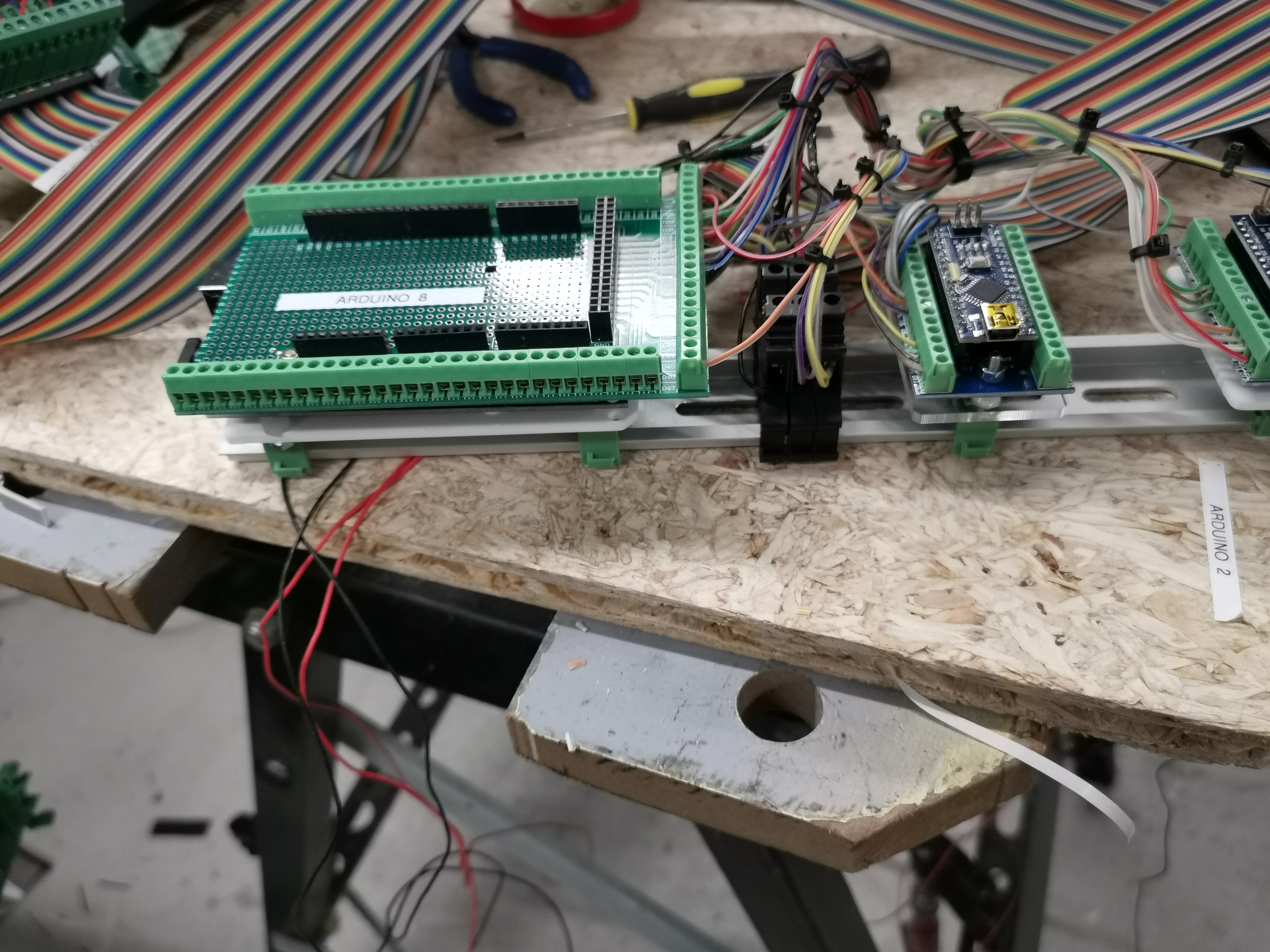
Roel, Is that a real Electrical panel? That is incredible backlighting of one of the most graphically complex panels in the SIM with very few LEDs! Roel, Is that a real Electrical panel? That is incredible backlighting of one of the most graphically complex panels in the SIM with very few LEDs! No not real ones, i bought them second hand in germany. No not real ones, i bought them second hand in germany. I was thinking the same thing. They look like they do a really good job spreading the light around, and with so few lights! I was thinking the same thing. They look like they do a really good job spreading the light around, and with so few lights! Hey Roel, This is awesome work you have done. Thanks for taking this on and sharing with everyone what is possible! The only minor issue I can see is the little bit of light bleed from one legend to the others. There are a couple things you can do to solve this. One way is to design light dividers out of a solid black material or include them into the back side design and use black paint to block out the light. Again, it is minor and we should easily be able to come up with a solution. I have not advanced my Davtron clock file very far at all because I have a real set. But it is worth advancing now that you have developed the software side of the clock. When I get some spare time later in this year I will get with you on this. Thanks again for taking this on and sharing your work Roel! Hey Roel, This is awesome work you have done. Thanks for taking this on and sharing with everyone what is possible! The only minor issue I can see is the little bit of light bleed from one legend to the others. There are a couple things you can do to solve this. One way is to design light dividers out of a solid black material or include them into the back side design and use black paint to block out the light. Again, it is minor and we should easily be able to come up with a solution. I have not advanced my Davtron clock file very far at all because I have a real set. But it is worth advancing now that you have developed the software side of the clock. When I get some spare time later in this year I will get with you on this. Thanks again for taking this on and sharing your work Roel! I have been busy wiring and programming my MIP So for now i use the Mobiflight for FSUIPC interfacing and wired my things according. I decided to use DIN mounted connectors and made special brackets to mount the Arduinos. So for now i am going to fully test this all and then mount the MIP! I have been busy wiring and programming my MIP So for now i use the Mobiflight for FSUIPC interfacing and wired my things according. I decided to use DIN mounted connectors and made special brackets to mount the Arduinos. So for now i am going to fully test this all and then mount the MIP! Wow Roel, That is a lot of work! It is also very interesting to see other ways to go about wiring up the MIP and components. It gives me ideas for my own project. I like the wire channels you have running along the bottom of the MIP. I need to look into that. Great update and keep us posted on your progress. Wow Roel, That is a lot of work! It is also very interesting to see other ways to go about wiring up the MIP and components. It gives me ideas for my own project. I like the wire channels you have running along the bottom of the MIP. I need to look into that. Great update and keep us posted on your progress. Hi Roel, I have two requests. I'm interested in cable management of the PC A/C, USB and VGA cables as well as the A/C input for devices and DC poser supplies. Do you have any examples? I realized I have 2 Pokeys cards, 3 UNO cards and 1 Mega card. 1 UNO and the Mega cards have shields. I need help with the 4 pin connectors. I can't find any discussion online. Seems as if each Arduino pin has a 4 pin connector. Can you point me to documentation or let me know how to use the 4 pins. Thanks Hi Roel, I have two requests. I'm interested in cable management of the PC A/C, USB and VGA cables as well as the A/C input for devices and DC poser supplies. Do you have any examples? I realized I have 2 Pokeys cards, 3 UNO cards and 1 Mega card. 1 UNO and the Mega cards have shields. I need help with the 4 pin connectors. I can't find any discussion online. Seems as if each Arduino pin has a 4 pin connector. Can you point me to documentation or let me know how to use the 4 pins. Thanks Roel's Learjet 45 simulator
![]()
![]()
They are from simparts.de and indeed very good quality.
too bad they stopped making learjet stuff
They are from simparts.de and indeed very good quality.
too bad they stopped making learjet stuff![]()
![]()
![]()
![]()
This also took alot of time.
I managed to use Air Manager to interface most of my MIP.
I think this software is great !
Except for the devices where i need to use FSUIPC like specific Jet45 Offsets.
I think it should be possible to also use Air Manager for this, but Air Manager does not use FSUIPC to interface but Simconnect.
Never the less i got an idea from someone on a forum to create custom gauges with only purpose to be able to use LVars from the Lua scripts in Air Manager.
But ...i have not figured that out yet...
I got 40 pin IDC breakout connectors from China to be able to disconnect the MIP for removal after being mounted.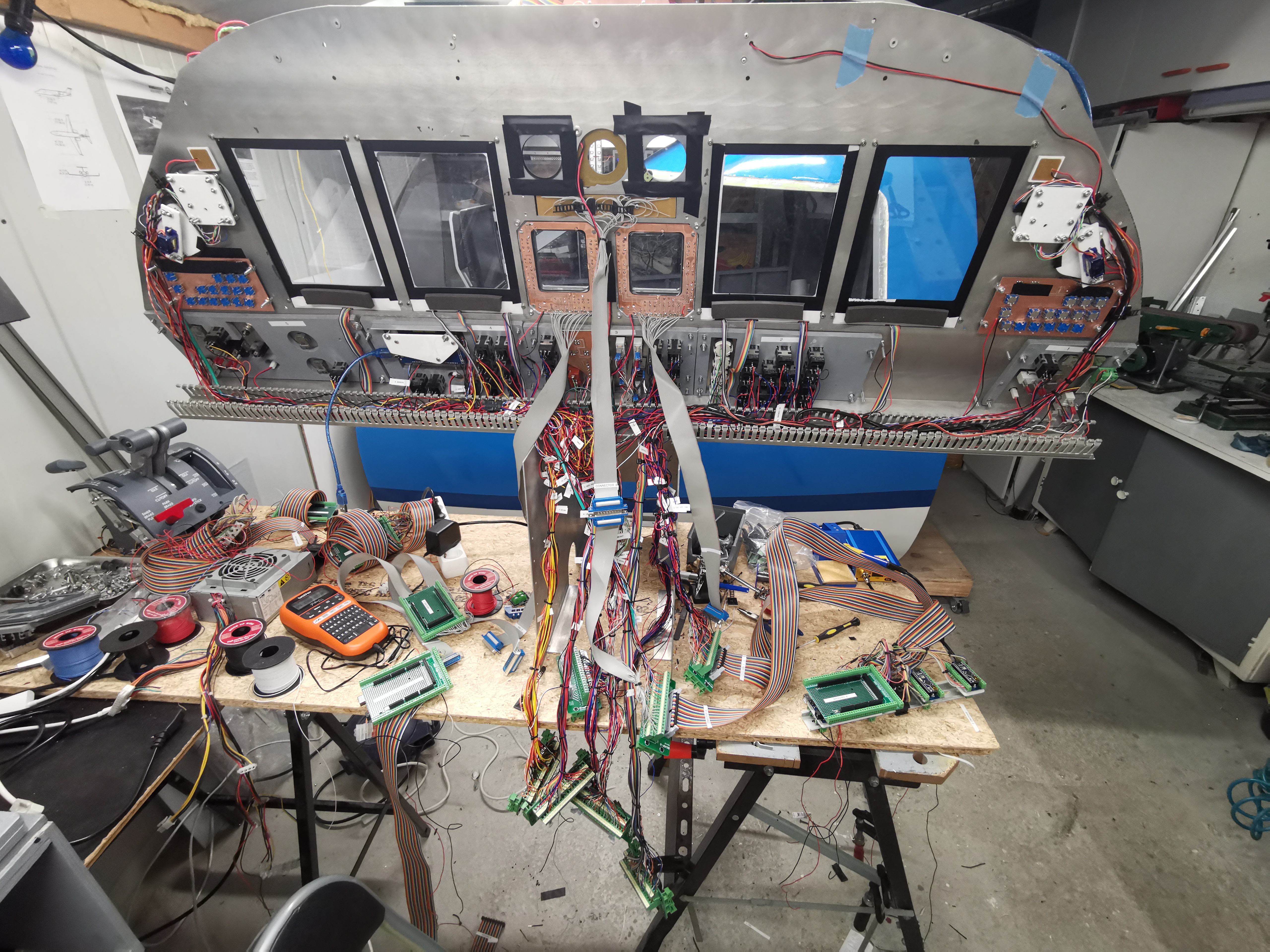
This also took alot of time.
I managed to use Air Manager to interface most of my MIP.
I think this software is great !
Except for the devices where i need to use FSUIPC like specific Jet45 Offsets.
I think it should be possible to also use Air Manager for this, but Air Manager does not use FSUIPC to interface but Simconnect.
Never the less i got an idea from someone on a forum to create custom gauges with only purpose to be able to use LVars from the Lua scripts in Air Manager.
But ...i have not figured that out yet...
I got 40 pin IDC breakout connectors from China to be able to disconnect the MIP for removal after being mounted.![]()
![]()
![]()
![]()
Forum NavigationRoel's Learjet 45 simulator
![]() #111 · January 1, 2021, 2:44 pmJason Hite
FlightDeckSoft
#111 · January 1, 2021, 2:44 pmJason Hite
FlightDeckSoft![]() #112 · January 1, 2021, 3:59 pm
#112 · January 1, 2021, 3:59 pm![]() #113 · January 1, 2021, 8:42 pm
#113 · January 1, 2021, 8:42 pm![]() #114 · January 2, 2021, 9:08 am
#114 · January 2, 2021, 9:08 am![]() #115 · January 2, 2021, 5:25 pmRoel has reacted to this post.Roel
#115 · January 2, 2021, 5:25 pmRoel has reacted to this post.Roel![]() #116 · March 5, 2021, 2:50 pm
#116 · March 5, 2021, 2:50 pm![]() #117 · March 5, 2021, 5:44 pm
#117 · March 5, 2021, 5:44 pm![]() #118 · March 11, 2021, 10:42 am
#118 · March 11, 2021, 10:42 am![]() #119 · March 13, 2021, 1:35 pm
#119 · March 13, 2021, 1:35 pm![]() #120 · March 13, 2021, 4:51 pm
#120 · March 13, 2021, 4:51 pm
2017-10-10