


Alright then. Will get few of them to start and see where it’s going to get me. Thanks Roel! Alright then. Will get few of them to start and see where it’s going to get me. Thanks Roel! Hi Roel, Amazing write up. I purchased Alan Norris' MIP. It came with 2 Pokeys cards and no scripts. He has tutorials here. I have a choice. Keep the Pokeys or change to Arduino. I think I'll change, thanks to your write up and I have several already. I purchased them to build my own back-lit panels. Somewhere I read you were building your own CDU. I assume you are using an Arduino. Its a shame Jason won't release the Arduino code to interface with Jet45 FMS. I see you have OpenCockpits experience. Two years ago I purchased the Opencockpits 737 FMS. Having difficulty understanding the sequence (.ini, compile, connectivity) to get this work to output keyboard strokes used by Jet45 FMS. My email address is dhs@dhdjsimmons.com or dhsimm4021@gmail.com. I would like to discuss SIOC with you and your experience. As you know, Opencockpits' documentation is not obvious and fragmented. If you would rather not, I understand. Please let me know either way. Thanks, Dave Simmons Hi Roel, Amazing write up. I purchased Alan Norris' MIP. It came with 2 Pokeys cards and no scripts. He has tutorials here. I have a choice. Keep the Pokeys or change to Arduino. I think I'll change, thanks to your write up and I have several already. I purchased them to build my own back-lit panels. Somewhere I read you were building your own CDU. I assume you are using an Arduino. Its a shame Jason won't release the Arduino code to interface with Jet45 FMS. I see you have OpenCockpits experience. Two years ago I purchased the Opencockpits 737 FMS. Having difficulty understanding the sequence (.ini, compile, connectivity) to get this work to output keyboard strokes used by Jet45 FMS. My email address is dhs@dhdjsimmons.com or dhsimm4021@gmail.com. I would like to discuss SIOC with you and your experience. As you know, Opencockpits' documentation is not obvious and fragmented. If you would rather not, I understand. Please let me know either way. Thanks, Dave Simmons Hi Roel, ... Its a shame Jason won't release the Arduino code to interface with Jet45 FMS. I'm frustrated that you keep saying I have not provided any interfacing information for the FMS. In fact Dave, I've given you the source header file which directly tells you what hex values the Arduino sends to the FMS software AND my user manual tells you exactly what keyboard key presses can be used if you don't use and Arduino! I've given you two options. Your assertion that my FMS software should somehow be compatible with every option available for hardware is unrealistic. That is why I've provided you with multiple interface options, all which require some work on your part if you don't use our plug-and-play solution. I understand that most are quite price conscious and locating a real UNS-1 keypad is not easy or cheap, and many users don't have coding experience like those of us on this thread. Ron and I will be working on a lower cost solution for this in the coming months, already having a working prototype CDU keypad circuit. Hopefully you can get something working for your CDU in the meantime. Your question boils down to "how can I get my OC CDU to output keyboard strokes, or code an Arduino to interface with the OC CDU directly". Once you solve either of these, you can interface with the FMS SW based on the interface options I have provided. Hi Roel, ... Its a shame Jason won't release the Arduino code to interface with Jet45 FMS. I'm frustrated that you keep saying I have not provided any interfacing information for the FMS. In fact Dave, I've given you the source header file which directly tells you what hex values the Arduino sends to the FMS software AND my user manual tells you exactly what keyboard key presses can be used if you don't use and Arduino! I've given you two options. Your assertion that my FMS software should somehow be compatible with every option available for hardware is unrealistic. That is why I've provided you with multiple interface options, all which require some work on your part if you don't use our plug-and-play solution. I understand that most are quite price conscious and locating a real UNS-1 keypad is not easy or cheap, and many users don't have coding experience like those of us on this thread. Ron and I will be working on a lower cost solution for this in the coming months, already having a working prototype CDU keypad circuit. Hopefully you can get something working for your CDU in the meantime. Your question boils down to "how can I get my OC CDU to output keyboard strokes, or code an Arduino to interface with the OC CDU directly". Once you solve either of these, you can interface with the FMS SW based on the interface options I have provided. Hi dave Jason is right, i also got the ino sketches for interfacing. i used the ifly737 suite, creating scripts for the ifly suite is quite easy. i used the oc keys card to interface to the ifly737 suite. Hi dave Jason is right, i also got the ino sketches for interfacing. i used the ifly737 suite, creating scripts for the ifly suite is quite easy. i used the oc keys card to interface to the ifly737 suite. Jason, Neither one of those questions are accurate. The real question is how does one create keyboard keystrokes to have the FMS respond. The table is evident. But I'm trying to understand how it works without a background on this type of hardware and app. The OC documentation is terrible except for the software they support for Boeing and Airbus. Does FMS automatically intercept any keystroke? Does the documentation assume that everyone understands how a Hagstrom card works? Many of us can understand if we see "real" working examples. Yes you provided the hex table for Arduino and the documentation for hardware key mapping. But how do they work with the .ini, usb, etc. Does the FMS automatically intercept keystrokes from a keyboard or keyboard emulator? Part of SIOC requires the widow be active to output keystrokes. Will the FMS be active or will it activate itself when a key event occurs. The documentation does not answer any of the. Atleast the AAS uses FSUIPC communication. The FMS is in the middle between AAS V1 and V2. All I'm trying to do is understand how everything fits. I understand and can code Arduino. I understand and can code Pokeys. What I can't understand is how Ron's CDU works with FMS. The FMS is a black box, I have no access to the CDU. User documentation includes how the pieces and parts work together with actual examples. I'm just trying to recreate that documentation in my mind trying to obtain as much information as possible. Two tables are not documentation. Jason, Neither one of those questions are accurate. The real question is how does one create keyboard keystrokes to have the FMS respond. The table is evident. But I'm trying to understand how it works without a background on this type of hardware and app. The OC documentation is terrible except for the software they support for Boeing and Airbus. Does FMS automatically intercept any keystroke? Does the documentation assume that everyone understands how a Hagstrom card works? Many of us can understand if we see "real" working examples. Yes you provided the hex table for Arduino and the documentation for hardware key mapping. But how do they work with the .ini, usb, etc. Does the FMS automatically intercept keystrokes from a keyboard or keyboard emulator? Part of SIOC requires the widow be active to output keystrokes. Will the FMS be active or will it activate itself when a key event occurs. The documentation does not answer any of the. Atleast the AAS uses FSUIPC communication. The FMS is in the middle between AAS V1 and V2. All I'm trying to do is understand how everything fits. I understand and can code Arduino. I understand and can code Pokeys. What I can't understand is how Ron's CDU works with FMS. The FMS is a black box, I have no access to the CDU. User documentation includes how the pieces and parts work together with actual examples. I'm just trying to recreate that documentation in my mind trying to obtain as much information as possible. Two tables are not documentation. Dave, The FMS will intercept all keystrokes whether or not it is in focus. I use a low level keyboard handler routine that is able to detect all keyboard inputs. That's why this will work with a keyboard encoder. Ill save you some trouble and heartache here: Sound good? Dave, The FMS will intercept all keystrokes whether or not it is in focus. I use a low level keyboard handler routine that is able to detect all keyboard inputs. That's why this will work with a keyboard encoder. Ill save you some trouble and heartache here: Sound good? Wow Jason Just knowing you used a low level keyboard hook makes a big difference. You should document what it is (not specifics) and the table, one can use any keyboard emulator (there are several). I am aware of the hooks and release for C++ and C# .NET. The OC FMS uses the IOCard USB KEYS, a keyboard emulator. What was confusing is that the OC documentation sucks. They mention 2 methods to communicate - Encoder_Keyes.exe and SIOC. In other online blogs (hard to find), Encoder_Keys.exe is old, SIOC easier. Docs not clear indicates both needed - not true. Also, how to setup SIOC is in 3 different manuals with no tieing examples. Bottom line it's doable. Seems as if any keyboard emulator, assigning keys to your Hagstrom table should work. BTW, the table is not a Hagstrom table but a keyboard emulator. There are many keyboard emulators. If the hook is based on Windows class, which I'm sure it is, it's easy. I assume that the A-Z, 1-9 keys are entered on the CDU screen. I assume the Arduino can be used as a keyboard emulator. But isn't there a limit of keys? Need 2 cards??? The OC card handles 88 keys and is 1/4 the price of Hagstrom and is why it's used. Language worse. Thanks for all your input. May I suggest? When V2 of the FMS is published, leave V1 as an alternative with the low level keyboard hook turned on. That way those who want to build their own CDU can use any keyboard emulator they want or any programmable CDU they want. I can help write the documentation if you want once I get this working. Wow Jason Just knowing you used a low level keyboard hook makes a big difference. You should document what it is (not specifics) and the table, one can use any keyboard emulator (there are several). I am aware of the hooks and release for C++ and C# .NET. The OC FMS uses the IOCard USB KEYS, a keyboard emulator. What was confusing is that the OC documentation sucks. They mention 2 methods to communicate - Encoder_Keyes.exe and SIOC. In other online blogs (hard to find), Encoder_Keys.exe is old, SIOC easier. Docs not clear indicates both needed - not true. Also, how to setup SIOC is in 3 different manuals with no tieing examples. Bottom line it's doable. Seems as if any keyboard emulator, assigning keys to your Hagstrom table should work. BTW, the table is not a Hagstrom table but a keyboard emulator. There are many keyboard emulators. If the hook is based on Windows class, which I'm sure it is, it's easy. I assume that the A-Z, 1-9 keys are entered on the CDU screen. I assume the Arduino can be used as a keyboard emulator. But isn't there a limit of keys? Need 2 cards??? The OC card handles 88 keys and is 1/4 the price of Hagstrom and is why it's used. Language worse. Thanks for all your input. May I suggest? When V2 of the FMS is published, leave V1 as an alternative with the low level keyboard hook turned on. That way those who want to build their own CDU can use any keyboard emulator they want or any programmable CDU they want. I can help write the documentation if you want once I get this working. I did some research about how to use my selfmade Davtron look a like chrono. I first made my hardware based on an Arduino Nano and a TM1637 7 segment module. Creating the hardware was pretty straightforward, interfacing seemed to be a challenge. My first idea was to write an Arduino sketch which displayed time, zulu time and a timer function. So then i tried a selfstudy in coding C# to use the available FSUIPC libraries and a library sharer named to interface. Then i stumbled upon software what i allready knew AirManager called. https://www.siminnovations.com/ This software was developed for creating gauges and panels, but it is greatly improved as of v3.x So what you need is an arduino sketch and a LUA script in Air Manager. So i made a prototype for interfacing the Chrono. First i made the LUA script in Air Manager function local_time(time) hours_str = string.format("%02.f", math.floor(time/3600)); end function msg_callback(id, payload) fsx_variable_subscribe("LOCAL TIME", "seconds", local_time) msg_port_id = hw_message_port_add ("ARDUINO_NANO_A" , msg_callback) LUA can read FS variables as desbribed here: And you can transfer these through the messageport and read the result in a console screen. Second you have to create an Arduino sketch, in my case for a Nano. #include <TM1637Display.h> #define INPUT_PIN 4 SiMessagePort* messagePort; int t_delay = 50; // Create a display object of type TM1637Display // Create an array that turns all segments ON // Create an array that turns all segments OFF byte ledPin1 = 8; // led on pin 8 unsigned long second; static void new_message_callback(uint16_t message_id, struct SiMessagePortPayload* payload) { if (message_id == 1) { } } void setup() { pinMode(8, OUTPUT); messagePort = new SiMessagePort(SI_MESSAGE_PORT_DEVICE_ARDUINO_NANO, SI_MESSAGE_PORT_CHANNEL_A, new_message_callback); void loop() { // Set the brightness to 5 (0=dimmest 7=brightest) messagePort->Tick(); display.showNumberDecEx(hh, 0b11100000, true, 2, 4); } How this basicly works is you read an FS variable en send it with an ID to the Arduino. if (message_id == 1) { So when a message with ID 1 is received it sends this back to the Air Manager console and set a variable hh with the sim hour variable. I still have to code the zulu time and timer function but after some playing around with this Air Manager i think i can do much more things with this. Some pics about my test I did some research about how to use my selfmade Davtron look a like chrono. I first made my hardware based on an Arduino Nano and a TM1637 7 segment module. Creating the hardware was pretty straightforward, interfacing seemed to be a challenge. My first idea was to write an Arduino sketch which displayed time, zulu time and a timer function. So then i tried a selfstudy in coding C# to use the available FSUIPC libraries and a library sharer named to interface. Then i stumbled upon software what i allready knew AirManager called. https://www.siminnovations.com/ This software was developed for creating gauges and panels, but it is greatly improved as of v3.x So what you need is an arduino sketch and a LUA script in Air Manager. So i made a prototype for interfacing the Chrono. First i made the LUA script in Air Manager function local_time(time) hours_str = string.format("%02.f", math.floor(time/3600)); end function msg_callback(id, payload) fsx_variable_subscribe("LOCAL TIME", "seconds", local_time) msg_port_id = hw_message_port_add ("ARDUINO_NANO_A" , msg_callback) LUA can read FS variables as desbribed here: And you can transfer these through the messageport and read the result in a console screen. Second you have to create an Arduino sketch, in my case for a Nano. #include <TM1637Display.h> #define INPUT_PIN 4 SiMessagePort* messagePort; int t_delay = 50; // Create a display object of type TM1637Display // Create an array that turns all segments ON // Create an array that turns all segments OFF byte ledPin1 = 8; // led on pin 8 unsigned long second; static void new_message_callback(uint16_t message_id, struct SiMessagePortPayload* payload) { if (message_id == 1) { } } void setup() { pinMode(8, OUTPUT); messagePort = new SiMessagePort(SI_MESSAGE_PORT_DEVICE_ARDUINO_NANO, SI_MESSAGE_PORT_CHANNEL_A, new_message_callback); void loop() { // Set the brightness to 5 (0=dimmest 7=brightest) messagePort->Tick(); display.showNumberDecEx(hh, 0b11100000, true, 2, 4); } How this basicly works is you read an FS variable en send it with an ID to the Arduino. if (message_id == 1) { So when a message with ID 1 is received it sends this back to the Air Manager console and set a variable hh with the sim hour variable. I still have to code the zulu time and timer function but after some playing around with this Air Manager i think i can do much more things with this. Some pics about my test Hi guys I wanted to share the progress of my cabin pressure display. I wanted to act the display as if it was a 7 segment display, so only numbers which change also change on the display. I am getting a great fan of the Air Manager software, this interfacing with Arduino is a great feature, but also creating instruments like a PFD is very possible. My display is not finished yet, i still am programming the manual pressure encoder. https://youtu.be/_xIbnvoPGiE Hi guys I wanted to share the progress of my cabin pressure display. I wanted to act the display as if it was a 7 segment display, so only numbers which change also change on the display. I am getting a great fan of the Air Manager software, this interfacing with Arduino is a great feature, but also creating instruments like a PFD is very possible. My display is not finished yet, i still am programming the manual pressure encoder. Hi Roel, Outstanding work you have done here with the pressurization display and controls! It is always exciting to see systems developed and working like this. I watched your short video and see that your LDG ALT and MANUAL encoders have a built in push switch. I had to go back in the books to make sure I did not miss that. After reviewing the books and to be clear for others watching your video, the two encoders do not have a push button built into them in the real Lear45. As you said in the video, to access the MANUAL function of the pressurization controls, you have to first select the square MANUAL PRESS switch below and to the right. Selecting it a second time returns the system back to auto mode. The LDG ALT encoder on the other hand is automatically activated if turned either direction and displays the landing altitude temporarily for five seconds and then returns to it's normal pressure display. There is much more to it than this but that's the basic idea. Again, great work Roel and thank you for sharing your progress! Hi Roel, Outstanding work you have done here with the pressurization display and controls! It is always exciting to see systems developed and working like this. I watched your short video and see that your LDG ALT and MANUAL encoders have a built in push switch. I had to go back in the books to make sure I did not miss that. After reviewing the books and to be clear for others watching your video, the two encoders do not have a push button built into them in the real Lear45. As you said in the video, to access the MANUAL function of the pressurization controls, you have to first select the square MANUAL PRESS switch below and to the right. Selecting it a second time returns the system back to auto mode. The LDG ALT encoder on the other hand is automatically activated if turned either direction and displays the landing altitude temporarily for five seconds and then returns to it's normal pressure display. There is much more to it than this but that's the basic idea. Again, great work Roel and thank you for sharing your progress! Roel's interfacing topic
![]()
![]()
![]()
![]()
but interfacing with oc cards is different.
for a fms interface via fsuipc for a default aircraft like the lear45 in fsx is more difficult.
i can mail you some info about this
but interfacing with oc cards is different.
for a fms interface via fsuipc for a default aircraft like the lear45 in fsx is more difficult.
i can mail you some info about this![]()
![]()
![]()
![]()
This seems an easy thing, but as i came along i found out it is not ...
These modules are available in several colours , i used an amber one.
I used an rtc module for the current time, and coding wasn't that hard.
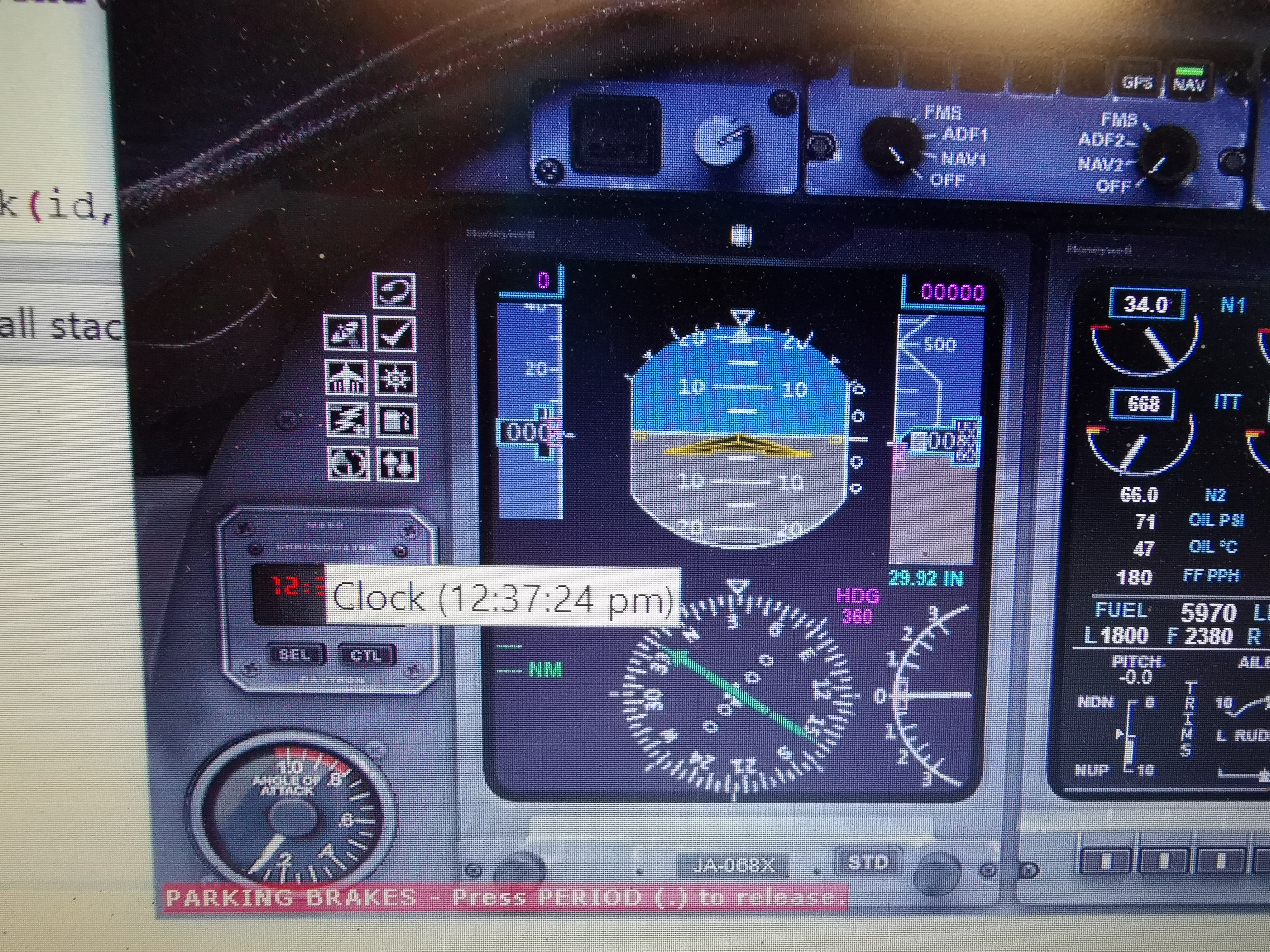
But this is the wrong way to go i realized; the PC time is not the sim time :S
This is also doable, i was on the good way but this takes alot of time, well for me that is 🙂
You can now interface with most Arduinos.
It is payware but after some study this is great.
It's not as easy as mobiflight, but is much more flexible with hardware.
Most users will use it to interface their developed gauges or panels with arduino, but there is an option now called message port.
This option uses the serialport of an arduino to send data over from and to the Air Manager software which interfaces to FS.
There are good wiki's available.
Here is the one about the messageport:
https://siminnovations.com/wiki/index.php?title=Arduino
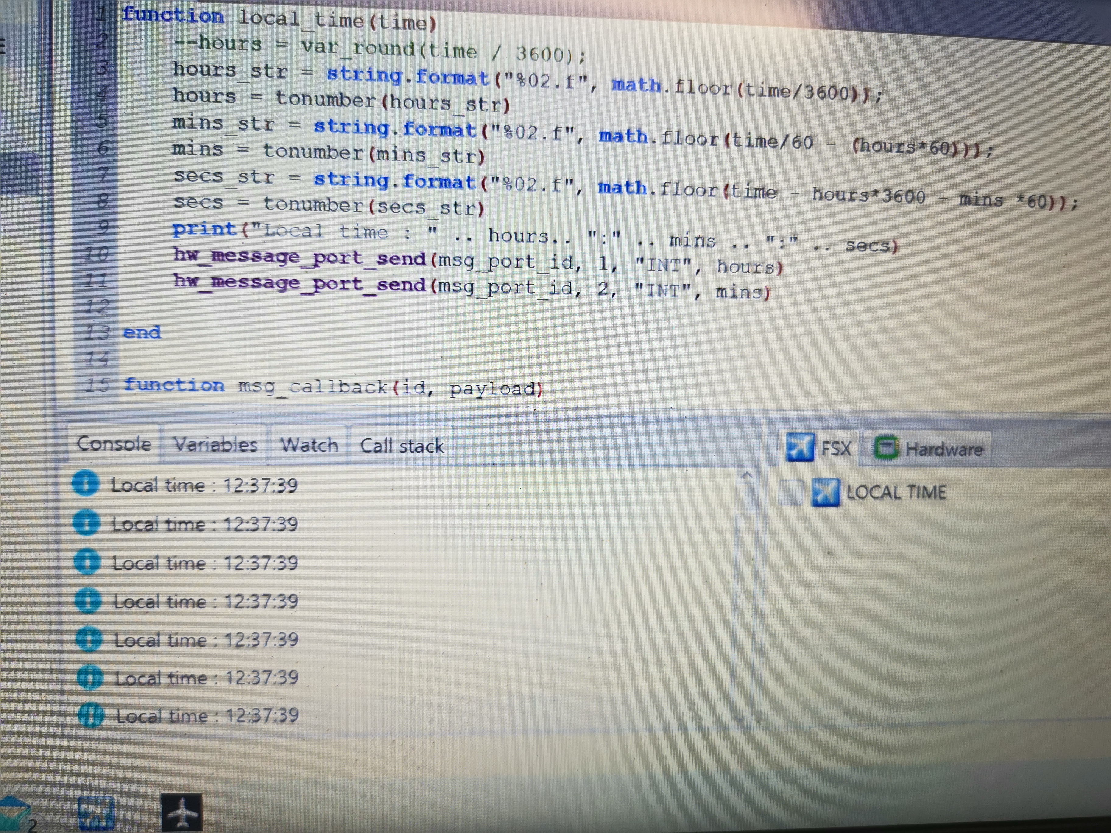
I am still working on it, but i can interface the sim time to my TM1637 .
hours = tonumber(hours_str)
mins_str = string.format("%02.f", math.floor(time/60 - (hours*60)));
mins = tonumber(mins_str)
secs_str = string.format("%02.f", math.floor(time - hours*3600 - mins *60));
secs = tonumber(secs_str)
print("Local time : " .. hours.. ":" .. mins .. ":" .. secs)
hw_message_port_send(msg_port_id, 1, "INT", hours)
hw_message_port_send(msg_port_id, 2, "INT", mins)
print("received message with id " .. id .. " and payload of " .. payload)
end
http://siminnovations.com/wiki/index.php?title=Fsx_variable_subscribe
#include <si_message_port.hpp>
// Define the connections pins
#define CLK 2
#define DIO 3
TM1637Display display = TM1637Display(CLK, DIO);
const uint8_t allON[] = {0xff, 0xff, 0xff, 0xff};
const uint8_t allOFF[] = {0x00, 0x00, 0x00, 0x00};
byte ledPin2 = 9; // led on pin 9
byte ledPin3 = 10; // led on pin 10
byte ledPin4 = 11; // led on pin 11
byte buttonPresses = 0; // how many times the button has been pressed
byte lastPressCount = 0; // to keep track of last press count
int hh = 00;
int mm = 00;
unsigned long millis_now = 0;
if (payload == NULL) {
messagePort->DebugMessage(SI_MESSAGE_PORT_LOG_LEVEL_INFO, (String)"Received without payload");
}
else {
switch(payload->type) {
case SI_MESSAGE_PORT_DATA_TYPE_BYTE:
messagePort->DebugMessage(SI_MESSAGE_PORT_LOG_LEVEL_INFO, (String)"Received " + payload->len + " bytes: " + payload->data_byte[0]);
break;
case SI_MESSAGE_PORT_DATA_TYPE_STRING:
messagePort->DebugMessage(SI_MESSAGE_PORT_LOG_LEVEL_INFO, (String)"Received string: " + payload->data_string);
break;
case SI_MESSAGE_PORT_DATA_TYPE_INTEGER:
messagePort->DebugMessage(SI_MESSAGE_PORT_LOG_LEVEL_INFO, (String)"Received " + payload->len + " ints: " + payload->data_int[0]);
messagePort->SendMessage(1, "Set Hours to clock"); // return payload to air manager console
hh = payload->data_int[0];
}
if (message_id == 2) {
messagePort->SendMessage(2, "Set Minutes to clock"); // return payload to air manager console
mm = payload->data_int[0];
}
break;
case SI_MESSAGE_PORT_DATA_TYPE_FLOAT:
messagePort->DebugMessage(SI_MESSAGE_PORT_LOG_LEVEL_INFO, (String)"Received " + payload->len + " floats: " + payload->data_float[0]);
break;
}
pinMode(9, OUTPUT);
pinMode(10, OUTPUT);
pinMode(11, OUTPUT);
pinMode(INPUT_PIN, INPUT_PULLUP);
}
display.setBrightness(5);
display.showNumberDecEx(mm, 0b11100000, true, 2, 2);
You can set a trigger when this ID is received and do something , in my case display the variable to the TM1637 module
messagePort->SendMessage(1, "Set Hours to clock"); // return payload to air manager console
hh = payload->data_int[0];
Big advantage is you can create Arduino sketches which interface with a FS quite easy (After you have figured it out)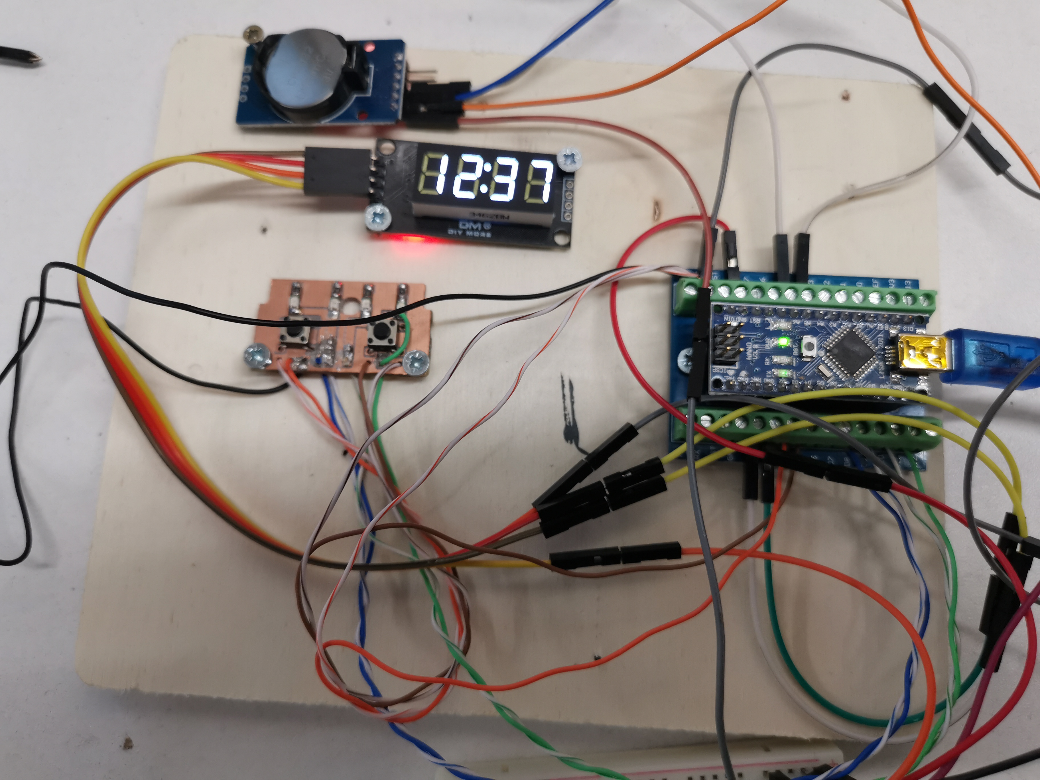
This seems an easy thing, but as i came along i found out it is not ...
These modules are available in several colours , i used an amber one.
I used an rtc module for the current time, and coding wasn't that hard.
But this is the wrong way to go i realized; the PC time is not the sim time :S
This is also doable, i was on the good way but this takes alot of time, well for me that is 🙂
You can now interface with most Arduinos.
It is payware but after some study this is great.
It's not as easy as mobiflight, but is much more flexible with hardware.
Most users will use it to interface their developed gauges or panels with arduino, but there is an option now called message port.
This option uses the serialport of an arduino to send data over from and to the Air Manager software which interfaces to FS.
There are good wiki's available.
Here is the one about the messageport:
https://siminnovations.com/wiki/index.php?title=Arduino
I am still working on it, but i can interface the sim time to my TM1637 .
hours = tonumber(hours_str)
mins_str = string.format("%02.f", math.floor(time/60 - (hours*60)));
mins = tonumber(mins_str)
secs_str = string.format("%02.f", math.floor(time - hours*3600 - mins *60));
secs = tonumber(secs_str)
print("Local time : " .. hours.. ":" .. mins .. ":" .. secs)
hw_message_port_send(msg_port_id, 1, "INT", hours)
hw_message_port_send(msg_port_id, 2, "INT", mins)
print("received message with id " .. id .. " and payload of " .. payload)
end
http://siminnovations.com/wiki/index.php?title=Fsx_variable_subscribe
#include <si_message_port.hpp>
// Define the connections pins
#define CLK 2
#define DIO 3
TM1637Display display = TM1637Display(CLK, DIO);
const uint8_t allON[] = {0xff, 0xff, 0xff, 0xff};
const uint8_t allOFF[] = {0x00, 0x00, 0x00, 0x00};
byte ledPin2 = 9; // led on pin 9
byte ledPin3 = 10; // led on pin 10
byte ledPin4 = 11; // led on pin 11
byte buttonPresses = 0; // how many times the button has been pressed
byte lastPressCount = 0; // to keep track of last press count
int hh = 00;
int mm = 00;
unsigned long millis_now = 0;
if (payload == NULL) {
messagePort->DebugMessage(SI_MESSAGE_PORT_LOG_LEVEL_INFO, (String)"Received without payload");
}
else {
switch(payload->type) {
case SI_MESSAGE_PORT_DATA_TYPE_BYTE:
messagePort->DebugMessage(SI_MESSAGE_PORT_LOG_LEVEL_INFO, (String)"Received " + payload->len + " bytes: " + payload->data_byte[0]);
break;
case SI_MESSAGE_PORT_DATA_TYPE_STRING:
messagePort->DebugMessage(SI_MESSAGE_PORT_LOG_LEVEL_INFO, (String)"Received string: " + payload->data_string);
break;
case SI_MESSAGE_PORT_DATA_TYPE_INTEGER:
messagePort->DebugMessage(SI_MESSAGE_PORT_LOG_LEVEL_INFO, (String)"Received " + payload->len + " ints: " + payload->data_int[0]);
messagePort->SendMessage(1, "Set Hours to clock"); // return payload to air manager console
hh = payload->data_int[0];
}
if (message_id == 2) {
messagePort->SendMessage(2, "Set Minutes to clock"); // return payload to air manager console
mm = payload->data_int[0];
}
break;
case SI_MESSAGE_PORT_DATA_TYPE_FLOAT:
messagePort->DebugMessage(SI_MESSAGE_PORT_LOG_LEVEL_INFO, (String)"Received " + payload->len + " floats: " + payload->data_float[0]);
break;
}
pinMode(9, OUTPUT);
pinMode(10, OUTPUT);
pinMode(11, OUTPUT);
pinMode(INPUT_PIN, INPUT_PULLUP);
}
display.setBrightness(5);
display.showNumberDecEx(mm, 0b11100000, true, 2, 2);
You can set a trigger when this ID is received and do something , in my case display the variable to the TM1637 module
messagePort->SendMessage(1, "Set Hours to clock"); // return payload to air manager console
hh = payload->data_int[0];
Big advantage is you can create Arduino sketches which interface with a FS quite easy (After you have figured it out)![]()
This seemed easy, since i am getting the hang of the Air Manager software, but controlling an arduino TFT screen took some time.
The issue with Arduino is, since it is open source A LOT of libraries and codes are available as examples but this also is confusing.
And managing the . and - signs also took some time ; i wanted to also change the distance of the numbers when a . occurs.
In fact there are a lot of these available for free allready.
My plan was to use the Mobiflight for interfacing, but i might switch to Air Manager.
But i made a video of my progress so far.
This seemed easy, since i am getting the hang of the Air Manager software, but controlling an arduino TFT screen took some time.
The issue with Arduino is, since it is open source A LOT of libraries and codes are available as examples but this also is confusing.
And managing the . and - signs also took some time ; i wanted to also change the distance of the numbers when a . occurs.
In fact there are a lot of these available for free allready.
My plan was to use the Mobiflight for interfacing, but i might switch to Air Manager.
But i made a video of my progress so far.![]()
Forum NavigationRoel's interfacing topic
![]() #11 · April 6, 2020, 7:48 am
#11 · April 6, 2020, 7:48 am![]() #12 · December 10, 2020, 1:15 pm
#12 · December 10, 2020, 1:15 pm![]() #13 · December 10, 2020, 1:36 pmRon Rollo and Roel have reacted to this post.Ron RolloRoelJason Hite
FlightDeckSoft
#13 · December 10, 2020, 1:36 pmRon Rollo and Roel have reacted to this post.Ron RolloRoelJason Hite
FlightDeckSoft![]() #14 · December 10, 2020, 1:52 pm
#14 · December 10, 2020, 1:52 pm![]() #15 · December 10, 2020, 5:52 pm
#15 · December 10, 2020, 5:52 pm![]() #16 · December 10, 2020, 6:22 pmJason Hite
FlightDeckSoft
#16 · December 10, 2020, 6:22 pmJason Hite
FlightDeckSoft![]() #17 · December 11, 2020, 10:03 am
#17 · December 11, 2020, 10:03 am![]() #18 · December 27, 2020, 7:17 am
#18 · December 27, 2020, 7:17 am![]() #19 · January 25, 2021, 5:53 am
#19 · January 25, 2021, 5:53 am![]() #20 · January 25, 2021, 1:53 pm
#20 · January 25, 2021, 1:53 pm
2017-10-10