


I was encouraged to start a topic here, so here we go . I started my Lear 45 project about a year ago and want to share my experience about interfacing the hardware to flightsim software. Therefore i, like most people in here, have switched to Arduino. One requirement you need and you guys probally have is a payed version of FSUIPC , especially if you use multiple PC's, but i believe Pete Dowson deserves to get payed! I will pass some of my findings in here to share with you guys I was encouraged to start a topic here, so here we go . I started my Lear 45 project about a year ago and want to share my experience about interfacing the hardware to flightsim software. Therefore i, like most people in here, have switched to Arduino. One requirement you need and you guys probally have is a payed version of FSUIPC , especially if you use multiple PC's, but i believe Pete Dowson deserves to get payed! I will pass some of my findings in here to share with you guys Interfacing Yokes and Rudder controls. Interfacing the potentio meters and buttons has become very easy with an Arduino Micro/Leonardo with an atmega32u4 chipset. To configure the number of pot meters and buttons you need to program it by creating a sketch with the Arduino editor which you can freely download at https://www.arduino.cc/en/Main/Software I am not a great Arduino programmer either, but i do know how to find usable sketches on the internet. https://www.instructables.com/id/Arduino-LeonardoMicro-as-Game-ControllerJoystick/ To configure the Arduino as an analog joystick, you need the arduino joystick library installed, this is available and explained at this site: https://github.com/MHeironimus/ArduinoJoystickLibrary Wiring is done like this: Turn potentio meters are connected with one of the outer pins to GND the other outer to VCC and the middle to A0 - A3 I have created (or used an existing sketch on the internet) to connect 3 pot meters and 4 buttons to the Arduino. #include <Joystick.h> // Reference the Joystick Library. // Create Joystick unsigned int xAxis = 0; // Set "initAutoSendState" to true for "Auto Send" mode or false for "Manual Send" mode. const bool initAutoSendState = true; void setup() { // Initialize Joystick Library } // Constant that maps the phyical pin to the joystick button. // Last state of the button void loop() { // Read pin values delay(50); xAxis = analogRead(A0)/4; Joystick.setXAxis(xAxis); } So to change the Arduino pin change this entry pinMode(9, INPUT_PULLUP); to whatever pin you have connected the button to, or change the analog pot meters by changing this entry: xAxis = analogRead(A0)/4; to A0 - A3 I have placed my test setup on youtube : https://youtu.be/74G0FDZ-4bk I am still in learning mode so i will m post my findings in here Interfacing Yokes and Rudder controls. Interfacing the potentio meters and buttons has become very easy with an Arduino Micro/Leonardo with an atmega32u4 chipset. To configure the number of pot meters and buttons you need to program it by creating a sketch with the Arduino editor which you can freely download at https://www.arduino.cc/en/Main/Software I am not a great Arduino programmer either, but i do know how to find usable sketches on the internet. https://www.instructables.com/id/Arduino-LeonardoMicro-as-Game-ControllerJoystick/ To configure the Arduino as an analog joystick, you need the arduino joystick library installed, this is available and explained at this site: https://github.com/MHeironimus/ArduinoJoystickLibrary Wiring is done like this: Turn potentio meters are connected with one of the outer pins to GND the other outer to VCC and the middle to A0 - A3 I have created (or used an existing sketch on the internet) to connect 3 pot meters and 4 buttons to the Arduino. #include <Joystick.h> // Reference the Joystick Library. // Create Joystick unsigned int xAxis = 0; // Set "initAutoSendState" to true for "Auto Send" mode or false for "Manual Send" mode. const bool initAutoSendState = true; void setup() { // Initialize Joystick Library } // Constant that maps the phyical pin to the joystick button. // Last state of the button void loop() { // Read pin values delay(50); xAxis = analogRead(A0)/4; Joystick.setXAxis(xAxis); } So to change the Arduino pin change this entry pinMode(9, INPUT_PULLUP); to whatever pin you have connected the button to, or change the analog pot meters by changing this entry: xAxis = analogRead(A0)/4; to A0 - A3 I have placed my test setup on youtube : I am still in learning mode so i will m post my findings in here Mobiflight A great (free) piece of software is mobiflight. Software can be downloaded at https://www.mobiflight.com/en/index.html I tried a 'proof of concept' with mobiflight to connect the Crew Warning Panel and will continue explaining this in a next topic soon. Video about this POC: https://youtu.be/ZLQe0_Xbf3M Mobiflight A great (free) piece of software is mobiflight. Software can be downloaded at https://www.mobiflight.com/en/index.html I tried a 'proof of concept' with mobiflight to connect the Crew Warning Panel and will continue explaining this in a next topic soon. Video about this POC: Hey Roel, What a great start to your Interfacing Topic thread! This will prove to be very helpful to other Hangar45 members who need a little help with understanding interfacing with Arduinos. It will also be a great place to archive your work. In the future, you will find yourself referring back to your own post while trying to trouble shoot issues or progress further in new areas! Hey Roel, What a great start to your Interfacing Topic thread! This will prove to be very helpful to other Hangar45 members who need a little help with understanding interfacing with Arduinos. It will also be a great place to archive your work. In the future, you will find yourself referring back to your own post while trying to trouble shoot issues or progress further in new areas! Hi again I will give a little example how to interface the CWP with an Arduino Mega 2650 and Mobiflight. -Mobiflight software -The CWP driver software (available at hangar45) So first install the Mobiflight software, this is pretty straight forward; next, next, finish and it is installed. In this tutorial I will configure the CWP - Left Oil Pressure Low LED and the test switch. So start FSX/Prepar3d and the CWP driver software. Now configure within Mobiflight an output for the L Oil pressure LED by clicking in the menu bar on Extras -> Settings -> Mobiflight Modules Click here on Add device, you can now add devices, in this case a LED / Output. So now we can assign a FSUIPC offset to this all. Make sure to select the Output TAB for LED's and Input for buttons and such!! Enter a description for the indicator , in this case CWP - L Oil Pressure Low. First enter the offset starting with 0x , so 0x7840 Now select the Display TAB at the top and select the correct Module, the previous defined PIN for the Output So that's it for LED Output. For the Button configuration first select the INPUT TAB!! Press the edit button at the right again. There is a little error in the Offset table , the TEST button is on Bit 1 of address 7843 in stead of bit 0. So enter in the On Press tab the Offset (0x7843) , change the size to 1 byte again, and select bit1 for the mask In the Set Value option , enter a 1, so if pressed the Offset bit is set to 1 and all indicators are on. In the On release TAB enter the same values as above except the set value to 0. Configuring mote buttons and LED's is just changing Offsets , PIN's on the Arduino. So hope this is helpful . Hi again I will give a little example how to interface the CWP with an Arduino Mega 2650 and Mobiflight. -Mobiflight software -The CWP driver software (available at hangar45) So first install the Mobiflight software, this is pretty straight forward; next, next, finish and it is installed. In this tutorial I will configure the CWP - Left Oil Pressure Low LED and the test switch. So start FSX/Prepar3d and the CWP driver software. Now configure within Mobiflight an output for the L Oil pressure LED by clicking in the menu bar on Extras -> Settings -> Mobiflight Modules Click here on Add device, you can now add devices, in this case a LED / Output. So now we can assign a FSUIPC offset to this all. Make sure to select the Output TAB for LED's and Input for buttons and such!! Enter a description for the indicator , in this case CWP - L Oil Pressure Low. First enter the offset starting with 0x , so 0x7840 Now select the Display TAB at the top and select the correct Module, the previous defined PIN for the Output So that's it for LED Output. For the Button configuration first select the INPUT TAB!! Press the edit button at the right again. There is a little error in the Offset table , the TEST button is on Bit 1 of address 7843 in stead of bit 0. So enter in the On Press tab the Offset (0x7843) , change the size to 1 byte again, and select bit1 for the mask In the Set Value option , enter a 1, so if pressed the Offset bit is set to 1 and all indicators are on. In the On release TAB enter the same values as above except the set value to 0. Configuring mote buttons and LED's is just changing Offsets , PIN's on the Arduino. So hope this is helpful . I have made a configuration which i am going to use for my Flight Controls. With the Arduino Micro Pro i am using 4 just straight connections, so i use no matrix connections to add more buttons on one Arduino. So on one Arduino Micro Pro i connect 4 analog inputs and 12 switches. I also have configured the hat switch on the Saitek Yoke. So wiring is done like this: Arduino sketch looks like this // Learjet 45 Flight Conrols // Pin A0 = X Axis #include "Joystick.h" //Joystick_ Joystick(JOYSTICK_DEFAULT_REPORT_ID,JOYSTICK_TYPE_JOYSTICK, 8, 0, true, true, true, true, false, false, false, false, false, false, false); void setup() { pinMode(A0, INPUT); pinMode(2, INPUT_PULLUP); Joystick.begin(); void loop() { Joystick.setRxAxisRange(-127, 127); // Analog Axes ---------------------------- // Z-Axis // X-Axis // Y-Axis // Y-Axis // Hat Switches ---------------------------- // Hatswitch 0 // Hatswitch 90 // Hatswitch 180 // Hatswitch 270 // Buttons -------------------------------------- // Button 1 // Button 2 // Button 3 // Button 4 // Button 5 // Button 6 // Button 7 // Button 8 delay(50); If you upload this to the arduino it will be available in windows as a joystick with X, Y, Z and Rx axis, a HAT with 4 positions and 8 buttons. I have made a configuration which i am going to use for my Flight Controls. With the Arduino Micro Pro i am using 4 just straight connections, so i use no matrix connections to add more buttons on one Arduino. So on one Arduino Micro Pro i connect 4 analog inputs and 12 switches. I also have configured the hat switch on the Saitek Yoke. So wiring is done like this: Arduino sketch looks like this // Learjet 45 Flight Conrols // Pin A0 = X Axis #include "Joystick.h" //Joystick_ Joystick(JOYSTICK_DEFAULT_REPORT_ID,JOYSTICK_TYPE_JOYSTICK, 8, 0, true, true, true, true, false, false, false, false, false, false, false); void setup() { pinMode(A0, INPUT); pinMode(2, INPUT_PULLUP); Joystick.begin(); void loop() { Joystick.setRxAxisRange(-127, 127); // Analog Axes ---------------------------- // Z-Axis // X-Axis // Y-Axis // Y-Axis // Hat Switches ---------------------------- // Hatswitch 0 // Hatswitch 90 // Hatswitch 180 // Hatswitch 270 // Buttons -------------------------------------- // Button 1 // Button 2 // Button 3 // Button 4 // Button 5 // Button 6 // Button 7 // Button 8 delay(50); If you upload this to the arduino it will be available in windows as a joystick with X, Y, Z and Rx axis, a HAT with 4 positions and 8 buttons. Roel, You can teach us all a lot about Arduinos and what is possible! Please keep up the great work and sharing! I am currently using Leo Bodnar cards for my flight controls but the goal is to switch everything in the cockpit over to Arduino interface cards, including the relay cards at some point. Thanks Roel! Roel, You can teach us all a lot about Arduinos and what is possible! Please keep up the great work and sharing! I am currently using Leo Bodnar cards for my flight controls but the goal is to switch everything in the cockpit over to Arduino interface cards, including the relay cards at some point. Thanks Roel! Arduino is indeed very cool! Arduino is indeed very cool! So... would it be possible to interface TQ using Arduino too? So... would it be possible to interface TQ using Arduino too? Yes, for sure! There is one annoying issue that I have not solve yet. So...still working on that ... Yes, for sure! There is one annoying issue that I have not solve yet. So...still working on that ...Roel's interfacing topic
![]()
I use prepar3d and used FSX before, i have no experience yet with Xplane.
In my previous project ( a Boeing 737) i used Open Cockpit cards to interface which worked great but have some disadvantages:
Arduino's are cheap, come in a lot of varieties, programming a sketch is a bit hard, but with tools like Mobiflight makes it very easy.
I use prepar3d and used FSX before, i have no experience yet with Xplane.
In my previous project ( a Boeing 737) i used Open Cockpit cards to interface which worked great but have some disadvantages:
Arduino's are cheap, come in a lot of varieties, programming a sketch is a bit hard, but with tools like Mobiflight makes it very easy.![]()
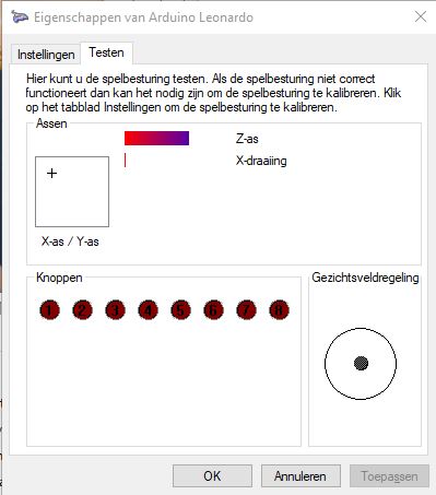
After connecting the Arduino out of the box to the PC, it is detected as a game controller!
Which is cool!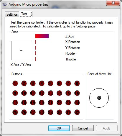
This site is a great start about the Arduino Micro/Leonardo programming.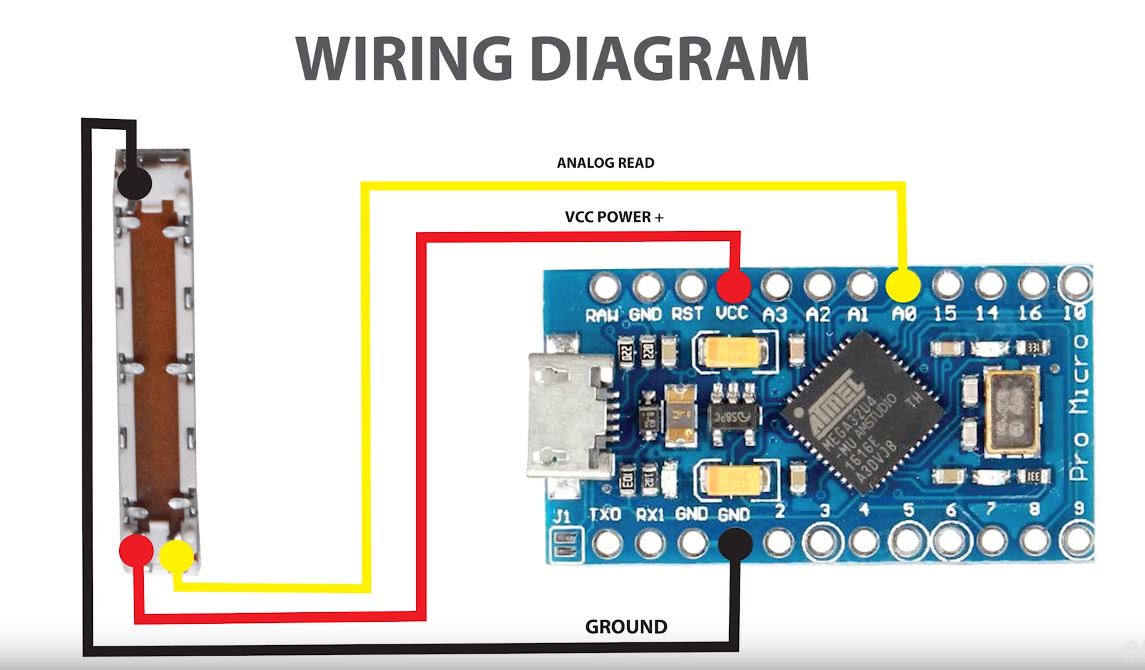
The buttons are connected with one pin to GND and the other to 2 - 15
You can easily adjust the pins or add more in this sketch.
Joystick_ Joystick;
unsigned int yAxis = 0;
unsigned int zAxis = 0;
//const bool testAutoState = false;
// Initialize Button Pins
pinMode(9, INPUT_PULLUP);
pinMode(10, INPUT_PULLUP);
pinMode(11, INPUT_PULLUP);
pinMode(12, INPUT_PULLUP);
Joystick.begin();
const int pinToButtonMap = 9;
int lastButtonState[4] = {0,0,0,0};
for (int index = 0; index < 4; index++)
{
int currentButtonState = !digitalRead(index + pinToButtonMap);
if (currentButtonState != lastButtonState[index])
{
Joystick.setButton(index, currentButtonState);
lastButtonState[index] = currentButtonState;
}
}
xAxis = map(xAxis,0,255,-127,127);
yAxis = analogRead(A1)/4;
yAxis = map(yAxis,0,255,-127,127);
zAxis = analogRead(A2)/4;
zAxis = map(zAxis,0,255,-127,127);
Joystick.setYAxis(yAxis);
Joystick.setZAxis(zAxis);
After connecting the Arduino out of the box to the PC, it is detected as a game controller!
Which is cool!
This site is a great start about the Arduino Micro/Leonardo programming.
The buttons are connected with one pin to GND and the other to 2 - 15
You can easily adjust the pins or add more in this sketch.
Joystick_ Joystick;
unsigned int yAxis = 0;
unsigned int zAxis = 0;
//const bool testAutoState = false;
// Initialize Button Pins
pinMode(9, INPUT_PULLUP);
pinMode(10, INPUT_PULLUP);
pinMode(11, INPUT_PULLUP);
pinMode(12, INPUT_PULLUP);
Joystick.begin();
const int pinToButtonMap = 9;
int lastButtonState[4] = {0,0,0,0};
for (int index = 0; index < 4; index++)
{
int currentButtonState = !digitalRead(index + pinToButtonMap);
if (currentButtonState != lastButtonState[index])
{
Joystick.setButton(index, currentButtonState);
lastButtonState[index] = currentButtonState;
}
}
xAxis = map(xAxis,0,255,-127,127);
yAxis = analogRead(A1)/4;
yAxis = map(yAxis,0,255,-127,127);
zAxis = analogRead(A2)/4;
zAxis = map(zAxis,0,255,-127,127);
Joystick.setYAxis(yAxis);
Joystick.setZAxis(zAxis);![]()
With it you can without any programming skills use Arduino cards to interface the sim.
Mobiflight uses only the Arduino Mega 2560 which is a great card.
I think i can configure 95% of the sim with Mobiflight.
Also there are very clear tutorials and documentation available in there.
With it you can without any programming skills use Arduino cards to interface the sim.
Mobiflight uses only the Arduino Mega 2560 which is a great card.
I think i can configure 95% of the sim with Mobiflight.
Also there are very clear tutorials and documentation available in there.![]()
![]()
What you need:
Connect an Arduino Mega to the PC; Mobiflight will recognize this card and asks to upload the firmware.
After doing this the card is ready for configuring.
All other CWP LED's will be the same to configure like this one.
The CWP driver software makes defined FSUIPC offsets available for, in this case, Mobiflight.
With the CWP driver maximized you cab see the status of all indicators.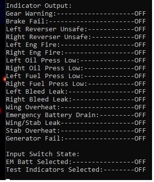
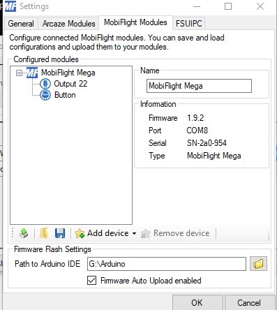
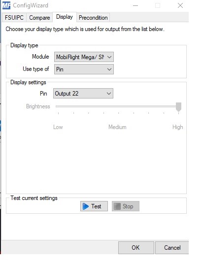
Select on which output pin it should be, in my case Pin 22 and give it a name f.i. Output 22.
Add another device; a button now, and again select a pin for the button.
Select now the upload button (most left icon) to upload this to the Arduino, and save this config.
Now click on the Edit buttons in the right.
In the documentation which comes along with the CWP driver you can get FSUIPC Offsets for the CWP.
Here you will see that bit 3 for Offset 7840 contains the status of the L Oil Pressure.
This Offset is an 8 bit address, you can in Mobiflight easily mask one bit out of this offset.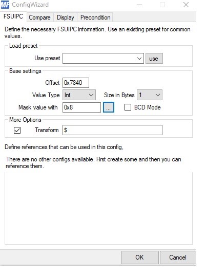
Change the size to 1 bit
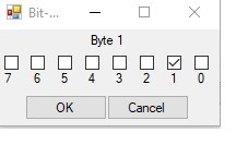
Now select the bit by pressing the ... square next to the mask value .
Unselect all bits , except bit 3.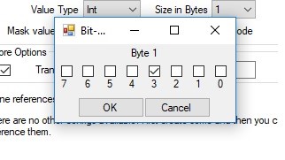
Again enter a description; i entered just TEST.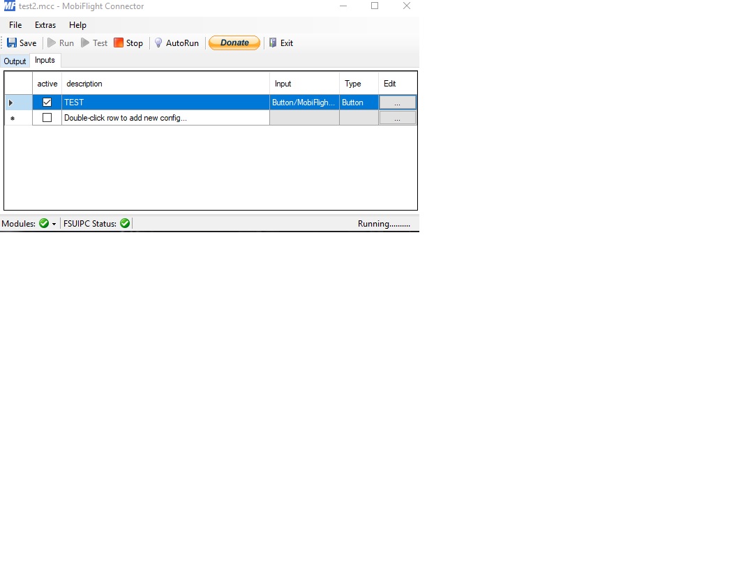
Here you can define what should happen on press and on release of the button.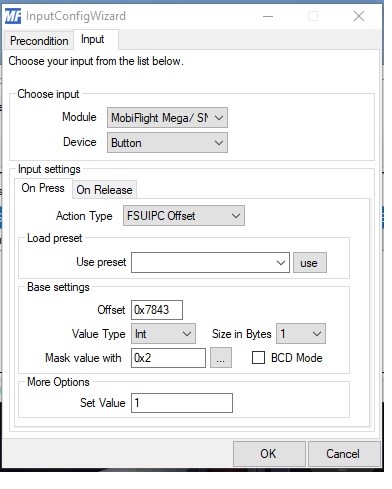
This will cause the indicators to set off when releasing the button.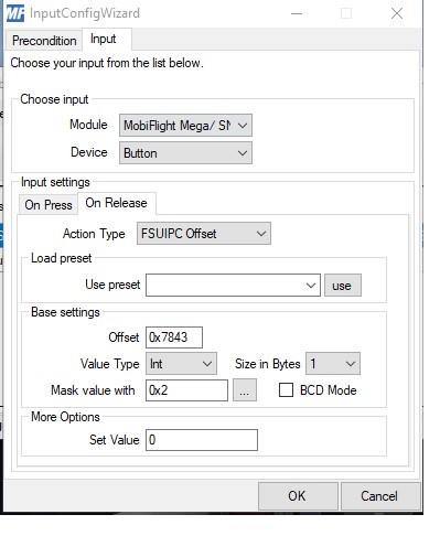
What you need:
Connect an Arduino Mega to the PC; Mobiflight will recognize this card and asks to upload the firmware.
After doing this the card is ready for configuring.
All other CWP LED's will be the same to configure like this one.
The CWP driver software makes defined FSUIPC offsets available for, in this case, Mobiflight.
With the CWP driver maximized you cab see the status of all indicators.
Select on which output pin it should be, in my case Pin 22 and give it a name f.i. Output 22.
Add another device; a button now, and again select a pin for the button.
Select now the upload button (most left icon) to upload this to the Arduino, and save this config.
Now click on the Edit buttons in the right.
In the documentation which comes along with the CWP driver you can get FSUIPC Offsets for the CWP.
Here you will see that bit 3 for Offset 7840 contains the status of the L Oil Pressure.
This Offset is an 8 bit address, you can in Mobiflight easily mask one bit out of this offset.
Change the size to 1 bit
Now select the bit by pressing the ... square next to the mask value .
Unselect all bits , except bit 3.
Again enter a description; i entered just TEST.
Here you can define what should happen on press and on release of the button.
This will cause the indicators to set off when releasing the button.![]()
Arduino's are cheap, so i use more to connect everything.
Since i use old Saitek yokes in my sim , i have wired all the buttons etc , and i will connect them as joystick buttons.
Still not sure if i will ever use most buttons .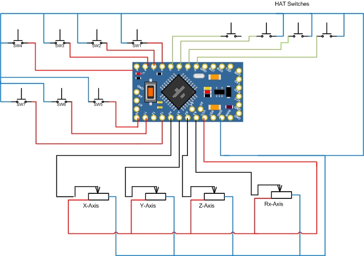
// Pin A1 = Y Axis
// Pin A2 = Z Axis
// Pin A3 = Rx Axis
// Pin 2 - 5 = Hat Switch
// Pin 6 - 16 Buttons
//
//--------------------------------------------------------------
Joystick_ Joystick(JOYSTICK_DEFAULT_REPORT_ID,
JOYSTICK_TYPE_JOYSTICK, 8,
JOYSTICK_DEFAULT_HATSWITCH_COUNT,
true, true, true, true, false, false,
false, false, false, false, false);
pinMode(A1, INPUT);
pinMode(A2, INPUT);
pinMode(A3, INPUT);
pinMode(3, INPUT_PULLUP);
pinMode(4, INPUT_PULLUP);
pinMode(5, INPUT_PULLUP);
pinMode(6, INPUT_PULLUP);
pinMode(7, INPUT_PULLUP);
pinMode(8, INPUT_PULLUP);
pinMode(9, INPUT_PULLUP);
pinMode(10, INPUT_PULLUP);
pinMode(11, INPUT_PULLUP);
pinMode(12, INPUT_PULLUP);
pinMode(13, INPUT_PULLUP);
pinMode(14, INPUT_PULLUP);
pinMode(15, INPUT_PULLUP);
pinMode(16, INPUT_PULLUP);
}
Joystick.setZAxisRange(-127, 127);
Joystick.setXAxisRange(-127, 127);
Joystick.setYAxisRange(-127, 127);
int zAxis = analogRead(A0);
Joystick.setZAxis(zAxis);
int xAxis = analogRead(A1);
Joystick.setXAxis(xAxis);
int yAxis = analogRead(A2);
Joystick.setYAxis(yAxis);
int RxAxis = analogRead(A3);
Joystick.setRxAxis(RxAxis);
int HatSwitch0 = !digitalRead(2);
if (HatSwitch0 == 1)
{
Joystick.setHatSwitch(HatSwitch0, 0);
}
int HatSwitch90 = !digitalRead(3);
if (HatSwitch90 == 1)
{
Joystick.setHatSwitch(HatSwitch90, 90);
}
int HatSwitch180 = !digitalRead(4);
if (HatSwitch180 == 1)
{
Joystick.setHatSwitch(HatSwitch180, 180);
}
int HatSwitch270 = !digitalRead(5);
if (HatSwitch270 == 1)
{
Joystick.setHatSwitch(HatSwitch270, 270);
}
int button1State = !digitalRead(6);
if (button1State == 1)
{
Joystick.pressButton(0);
}
else
{
Joystick.releaseButton(0);
}
int button2State = !digitalRead(7);
if (button2State == 1)
{
Joystick.pressButton(1);
}
else
{
Joystick.releaseButton(1);
}
int button3State = !digitalRead(8);
if (button3State == 1)
{
Joystick.pressButton(2);
}
else
{
Joystick.releaseButton(2);
}
int button4State = !digitalRead(9);
if (button4State == 1)
{
Joystick.pressButton(3);
}
else
{
Joystick.releaseButton(3);
}
int button5State = !digitalRead(10);
if (button5State == 1)
{
Joystick.pressButton(4);
}
else
{
Joystick.releaseButton(4);
}
int button6State = !digitalRead(14);
if (button6State == 1)
{
Joystick.pressButton(5);
}
else
{
Joystick.releaseButton(5);
}
int button7State = !digitalRead(15);
if (button7State == 1)
{
Joystick.pressButton(6);
}
else
{
Joystick.releaseButton(6);
}
int button8State = !digitalRead(16);
if (button8State == 1)
{
Joystick.pressButton(7);
}
else
{
Joystick.releaseButton(7);
}
}
Arduino's are cheap, so i use more to connect everything.
Since i use old Saitek yokes in my sim , i have wired all the buttons etc , and i will connect them as joystick buttons.
Still not sure if i will ever use most buttons .
// Pin A1 = Y Axis
// Pin A2 = Z Axis
// Pin A3 = Rx Axis
// Pin 2 - 5 = Hat Switch
// Pin 6 - 16 Buttons
//
//--------------------------------------------------------------
Joystick_ Joystick(JOYSTICK_DEFAULT_REPORT_ID,
JOYSTICK_TYPE_JOYSTICK, 8,
JOYSTICK_DEFAULT_HATSWITCH_COUNT,
true, true, true, true, false, false,
false, false, false, false, false);
pinMode(A1, INPUT);
pinMode(A2, INPUT);
pinMode(A3, INPUT);
pinMode(3, INPUT_PULLUP);
pinMode(4, INPUT_PULLUP);
pinMode(5, INPUT_PULLUP);
pinMode(6, INPUT_PULLUP);
pinMode(7, INPUT_PULLUP);
pinMode(8, INPUT_PULLUP);
pinMode(9, INPUT_PULLUP);
pinMode(10, INPUT_PULLUP);
pinMode(11, INPUT_PULLUP);
pinMode(12, INPUT_PULLUP);
pinMode(13, INPUT_PULLUP);
pinMode(14, INPUT_PULLUP);
pinMode(15, INPUT_PULLUP);
pinMode(16, INPUT_PULLUP);
}
Joystick.setZAxisRange(-127, 127);
Joystick.setXAxisRange(-127, 127);
Joystick.setYAxisRange(-127, 127);
int zAxis = analogRead(A0);
Joystick.setZAxis(zAxis);
int xAxis = analogRead(A1);
Joystick.setXAxis(xAxis);
int yAxis = analogRead(A2);
Joystick.setYAxis(yAxis);
int RxAxis = analogRead(A3);
Joystick.setRxAxis(RxAxis);
int HatSwitch0 = !digitalRead(2);
if (HatSwitch0 == 1)
{
Joystick.setHatSwitch(HatSwitch0, 0);
}
int HatSwitch90 = !digitalRead(3);
if (HatSwitch90 == 1)
{
Joystick.setHatSwitch(HatSwitch90, 90);
}
int HatSwitch180 = !digitalRead(4);
if (HatSwitch180 == 1)
{
Joystick.setHatSwitch(HatSwitch180, 180);
}
int HatSwitch270 = !digitalRead(5);
if (HatSwitch270 == 1)
{
Joystick.setHatSwitch(HatSwitch270, 270);
}
int button1State = !digitalRead(6);
if (button1State == 1)
{
Joystick.pressButton(0);
}
else
{
Joystick.releaseButton(0);
}
int button2State = !digitalRead(7);
if (button2State == 1)
{
Joystick.pressButton(1);
}
else
{
Joystick.releaseButton(1);
}
int button3State = !digitalRead(8);
if (button3State == 1)
{
Joystick.pressButton(2);
}
else
{
Joystick.releaseButton(2);
}
int button4State = !digitalRead(9);
if (button4State == 1)
{
Joystick.pressButton(3);
}
else
{
Joystick.releaseButton(3);
}
int button5State = !digitalRead(10);
if (button5State == 1)
{
Joystick.pressButton(4);
}
else
{
Joystick.releaseButton(4);
}
int button6State = !digitalRead(14);
if (button6State == 1)
{
Joystick.pressButton(5);
}
else
{
Joystick.releaseButton(5);
}
int button7State = !digitalRead(15);
if (button7State == 1)
{
Joystick.pressButton(6);
}
else
{
Joystick.releaseButton(6);
}
int button8State = !digitalRead(16);
if (button8State == 1)
{
Joystick.pressButton(7);
}
else
{
Joystick.releaseButton(7);
}
}![]()
![]()
And with all the available software and sketches it does not require alot of programming skills.
And with all the available software and sketches it does not require alot of programming skills.![]()
![]()
I am planning to wire up my TQ also like this.
You just connect more Arduino's.
Every Arduino is available in Windows with the same name "Arduino Leonardo" under game controllers.
It would be nice to rename them to "Flight controls Capt" or something.
I have found some fixes on the internet, but they all don't work yet, or mess up the Arduino libraries.
I have read that it is a legal issue, Arduino only wants the Arduino name present in Windows.
Forum NavigationRoel's interfacing topic
![]() #1 · January 23, 2020, 1:06 pm
#1 · January 23, 2020, 1:06 pm![]() #2 · January 23, 2020, 1:20 pmRon Rollo has reacted to this post.Ron Rollo
#2 · January 23, 2020, 1:20 pmRon Rollo has reacted to this post.Ron Rollo![]() #3 · January 23, 2020, 2:05 pmRon Rollo has reacted to this post.Ron Rollo
#3 · January 23, 2020, 2:05 pmRon Rollo has reacted to this post.Ron Rollo![]() #4 · January 24, 2020, 9:27 am
#4 · January 24, 2020, 9:27 am![]() #5 · February 10, 2020, 4:31 amRon Rollo has reacted to this post.Ron Rollo
#5 · February 10, 2020, 4:31 amRon Rollo has reacted to this post.Ron Rollo![]() #6 · April 3, 2020, 5:37 amRon Rollo has reacted to this post.Ron Rollo
#6 · April 3, 2020, 5:37 amRon Rollo has reacted to this post.Ron Rollo![]() #7 · April 3, 2020, 7:30 am
#7 · April 3, 2020, 7:30 am![]() #8 · April 3, 2020, 7:31 am
#8 · April 3, 2020, 7:31 am![]() #9 · April 4, 2020, 8:24 pm
#9 · April 4, 2020, 8:24 pm![]() #10 · April 5, 2020, 6:11 am
#10 · April 5, 2020, 6:11 am
2017-10-10