


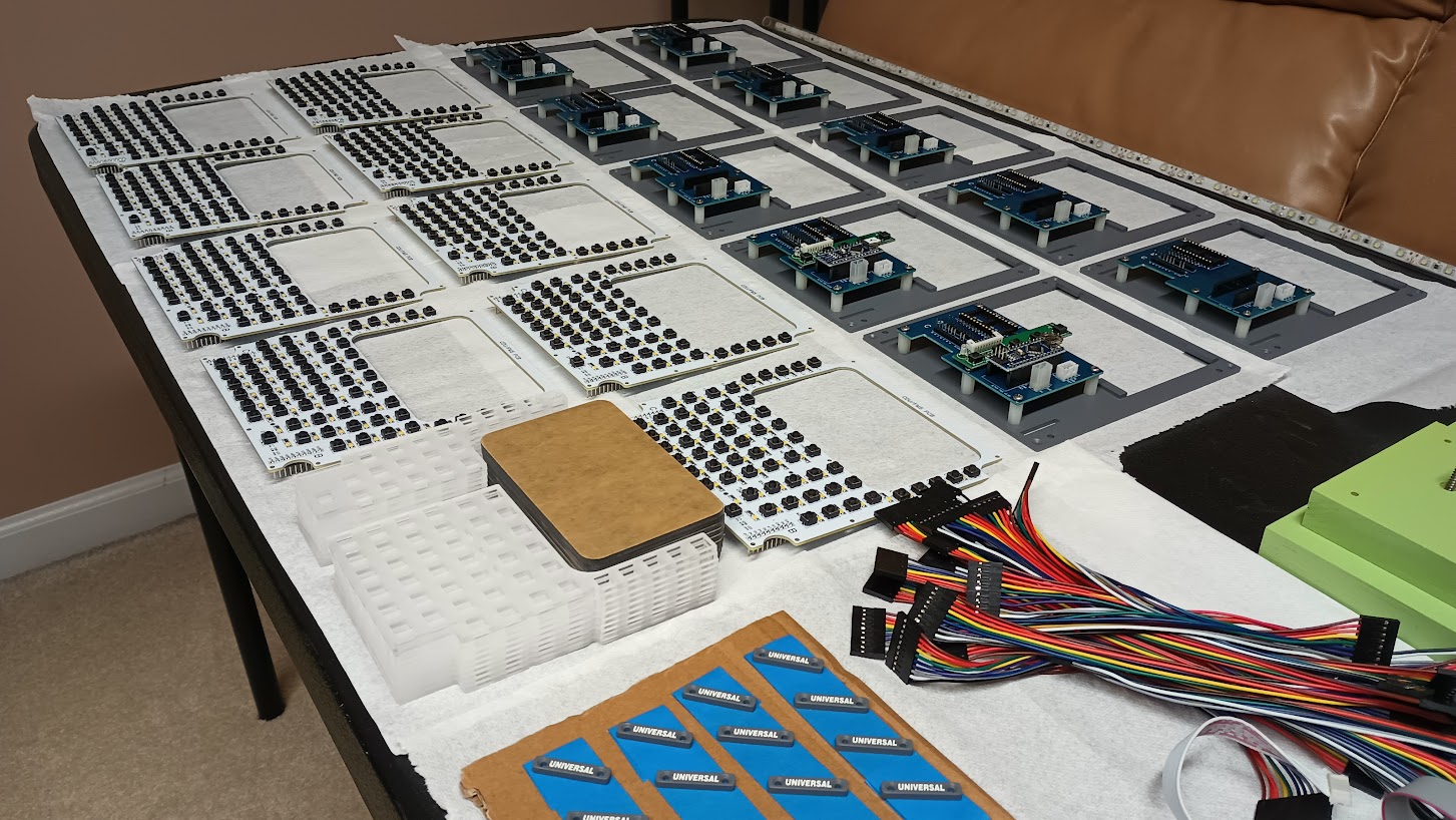
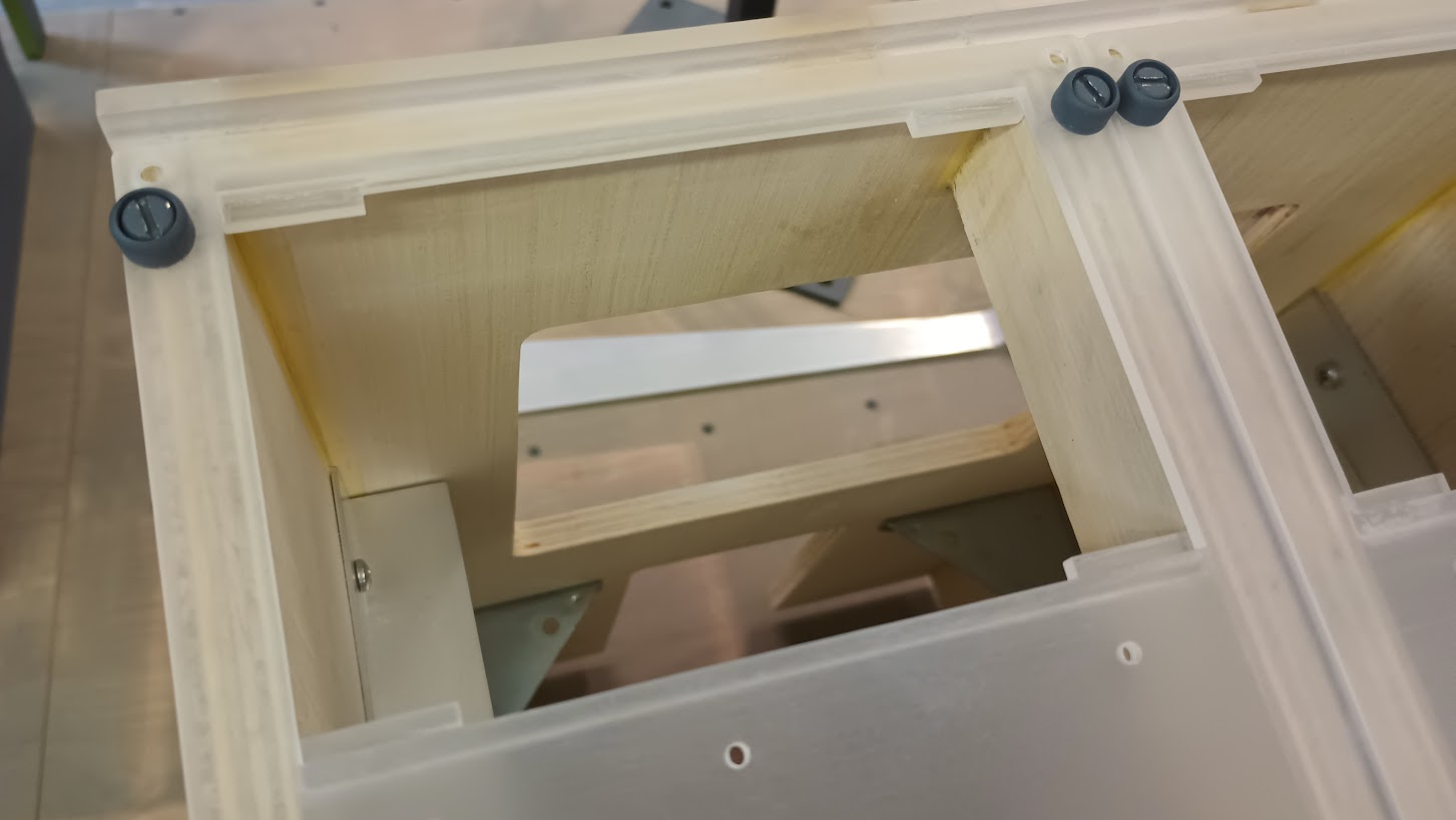
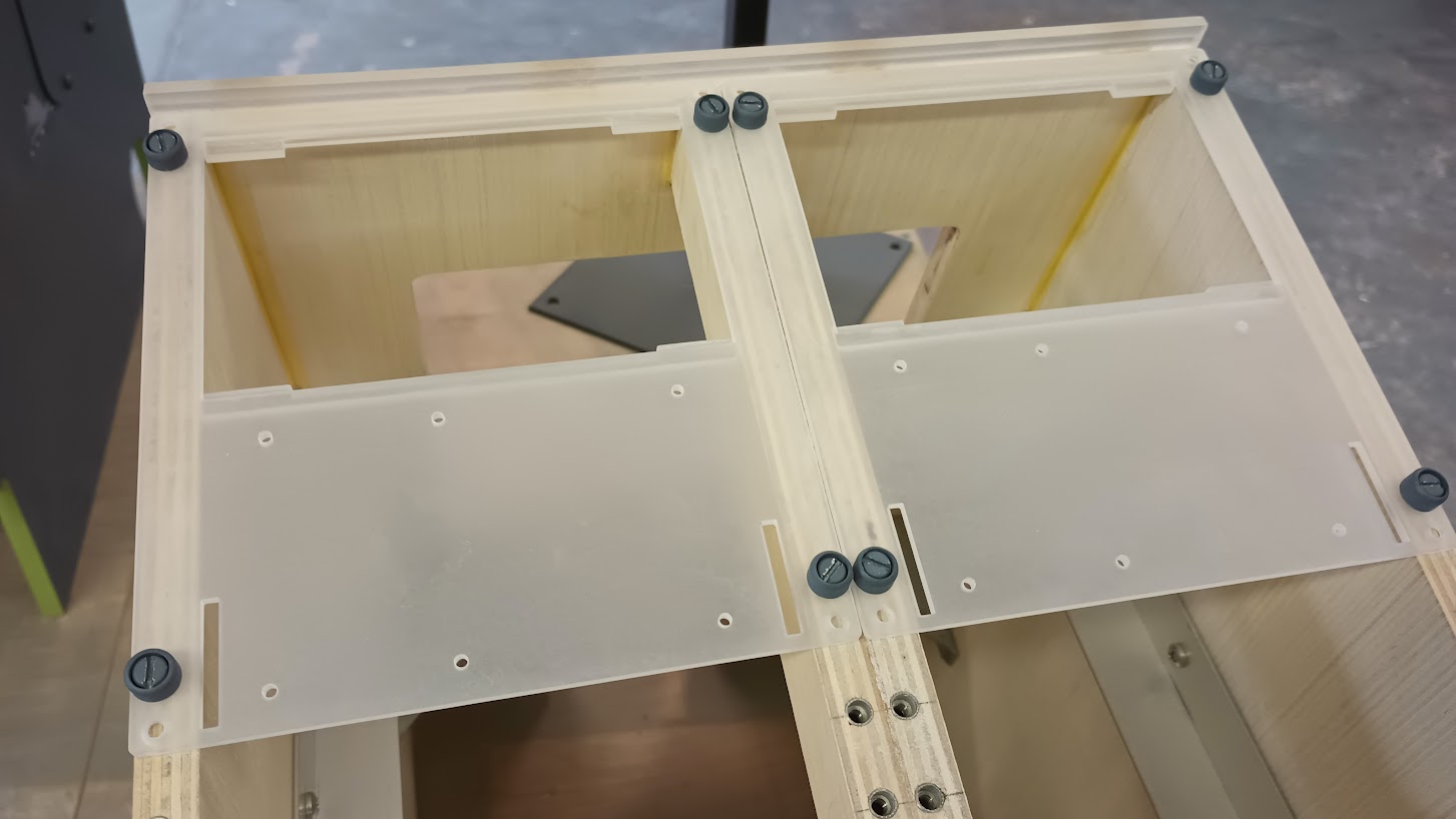
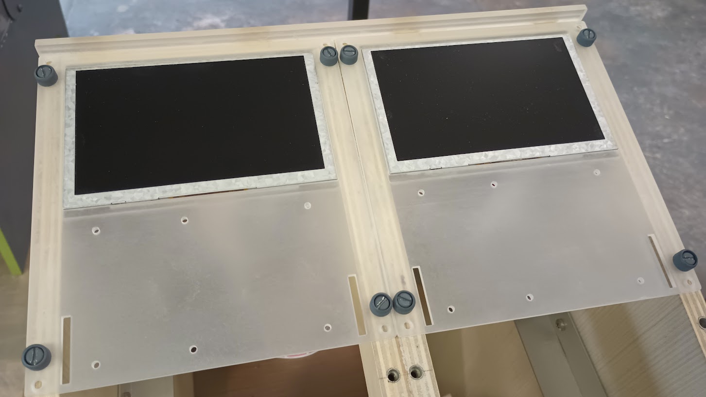
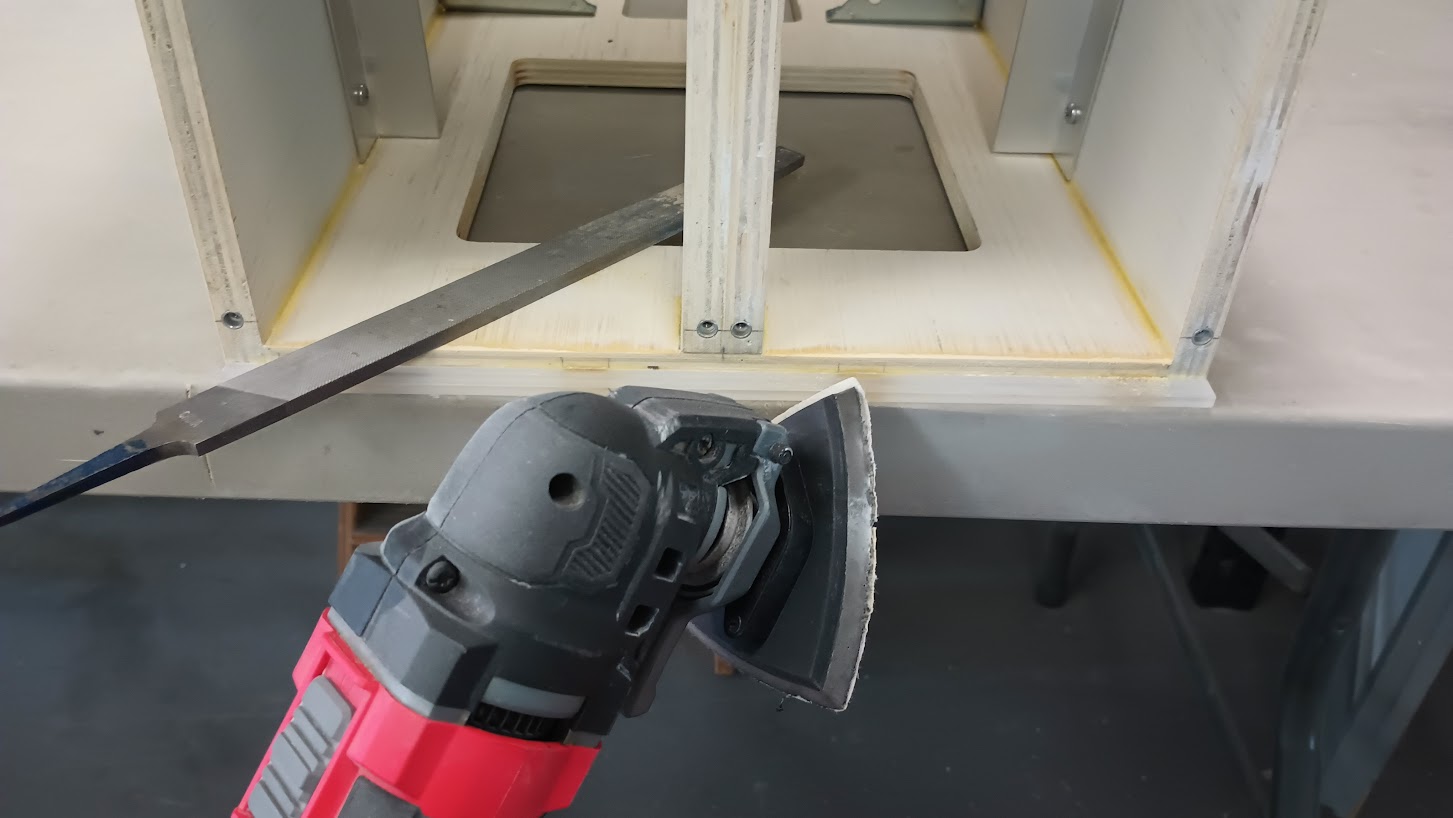
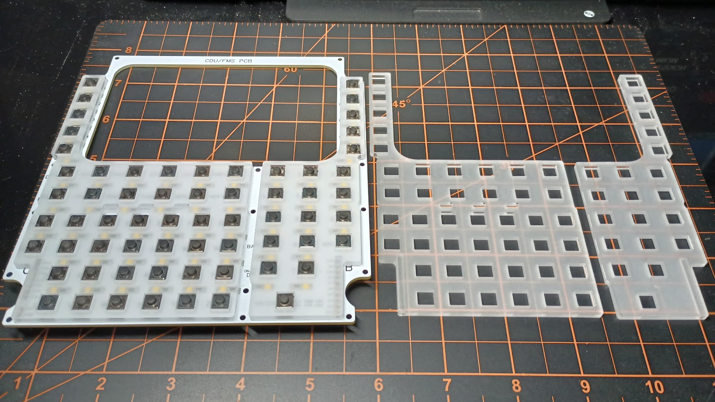
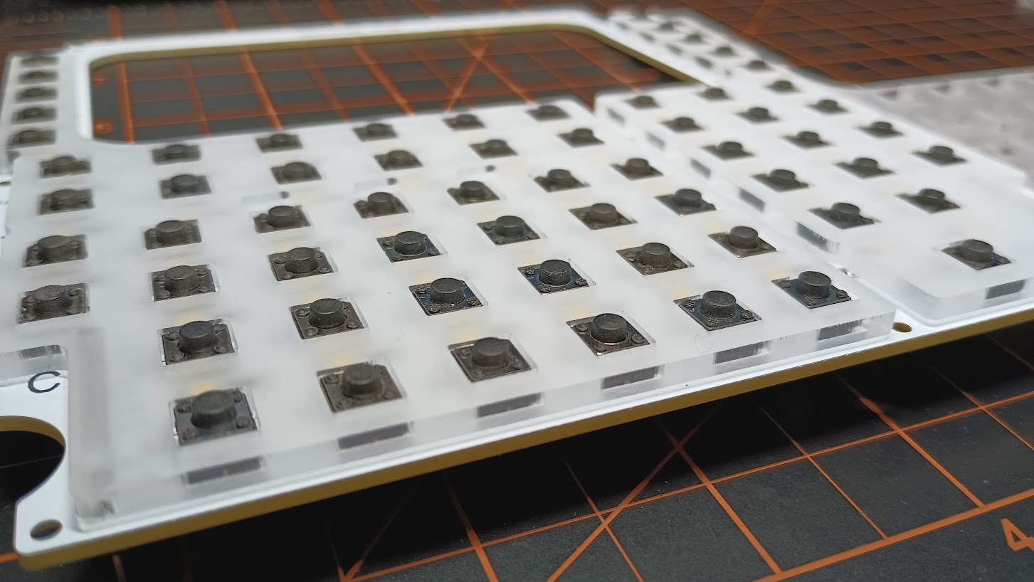
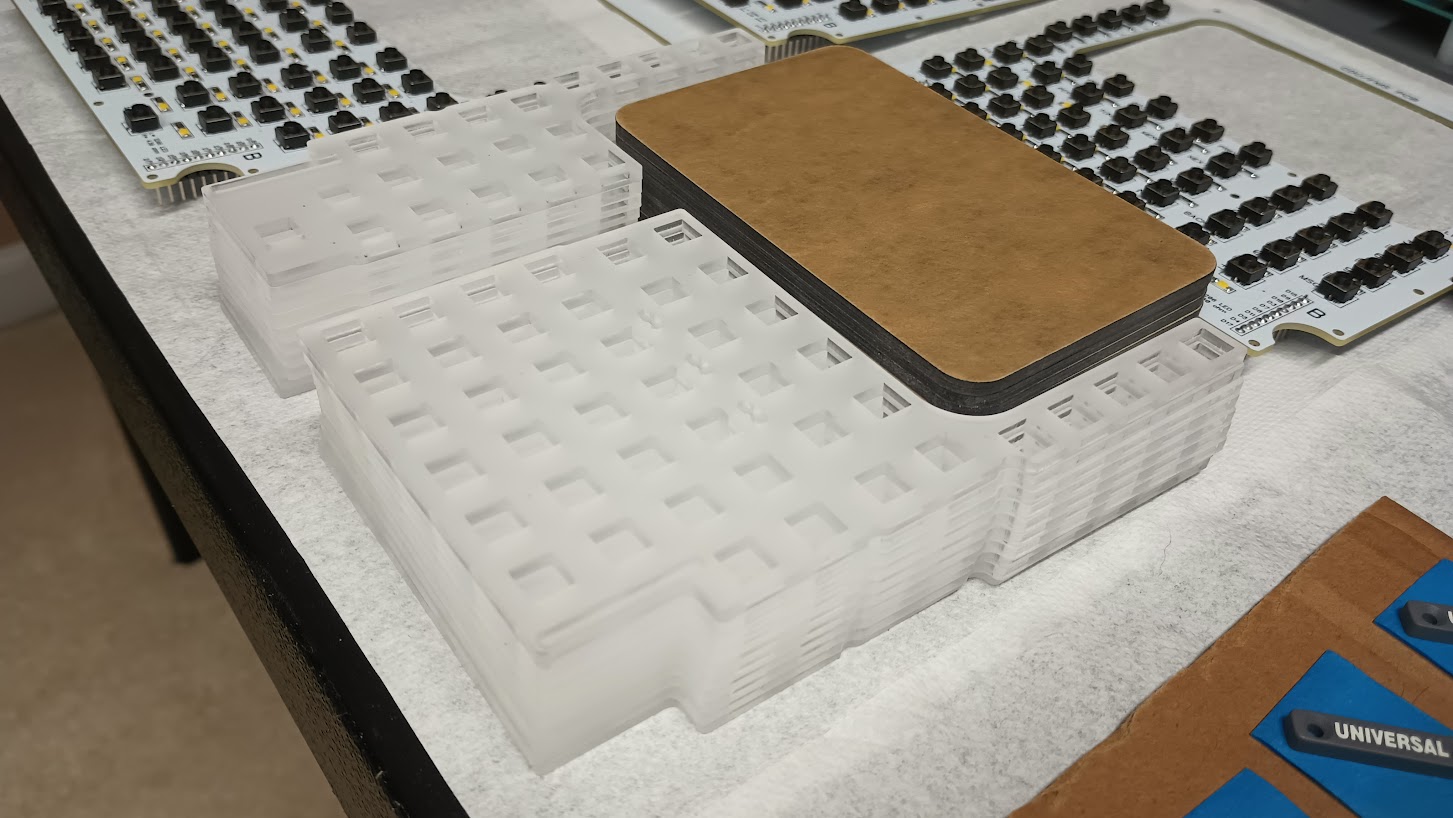
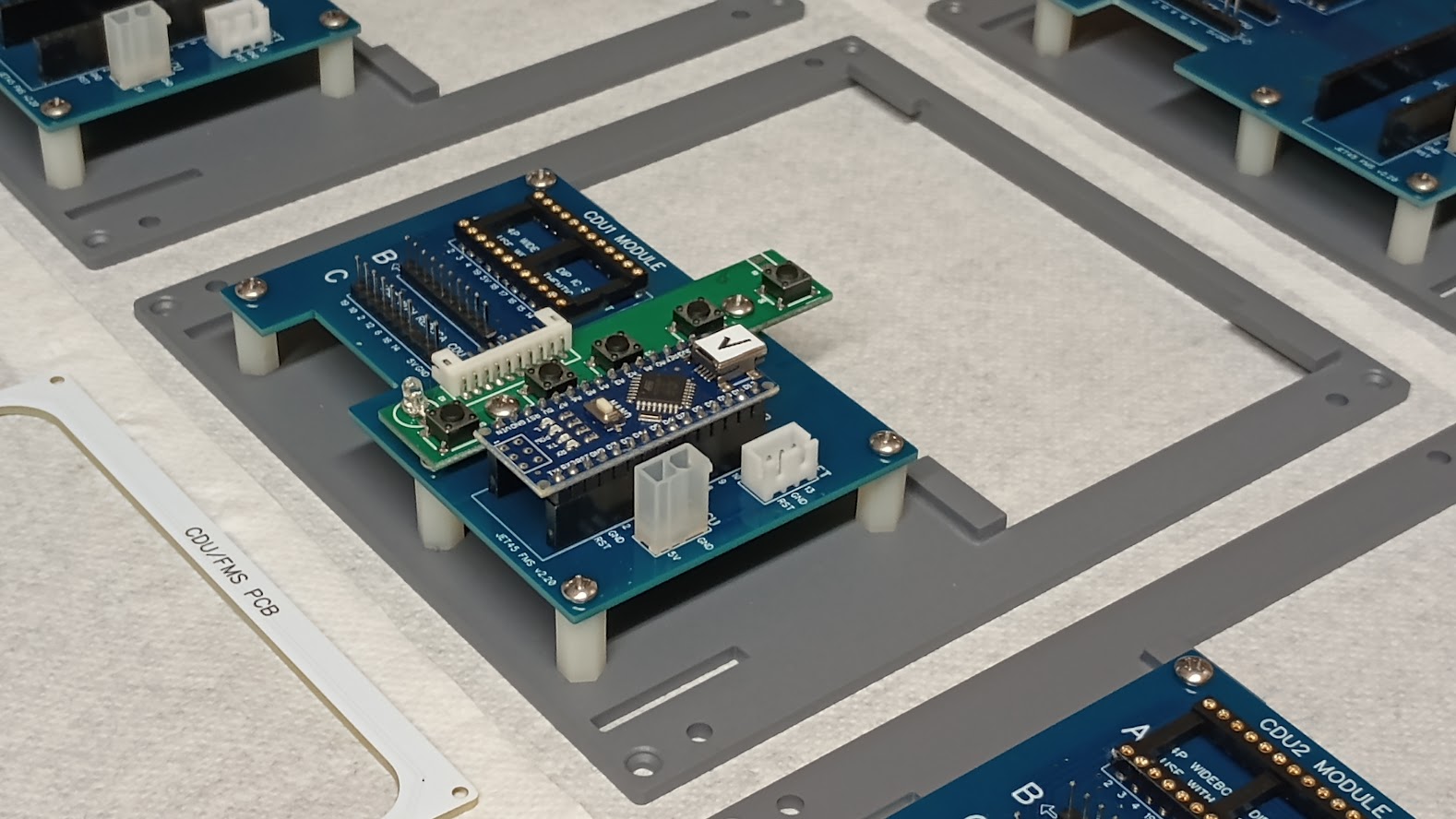
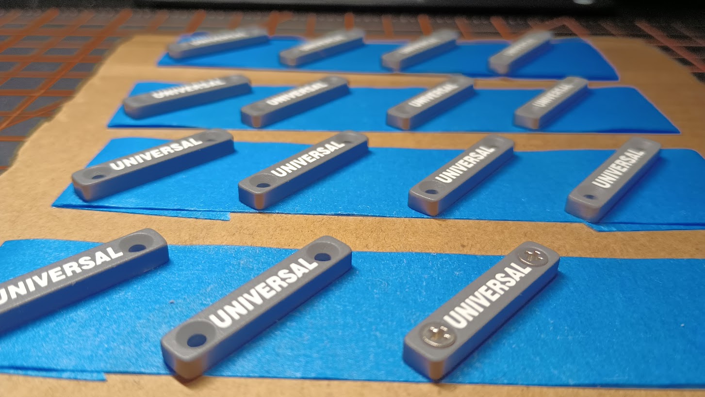
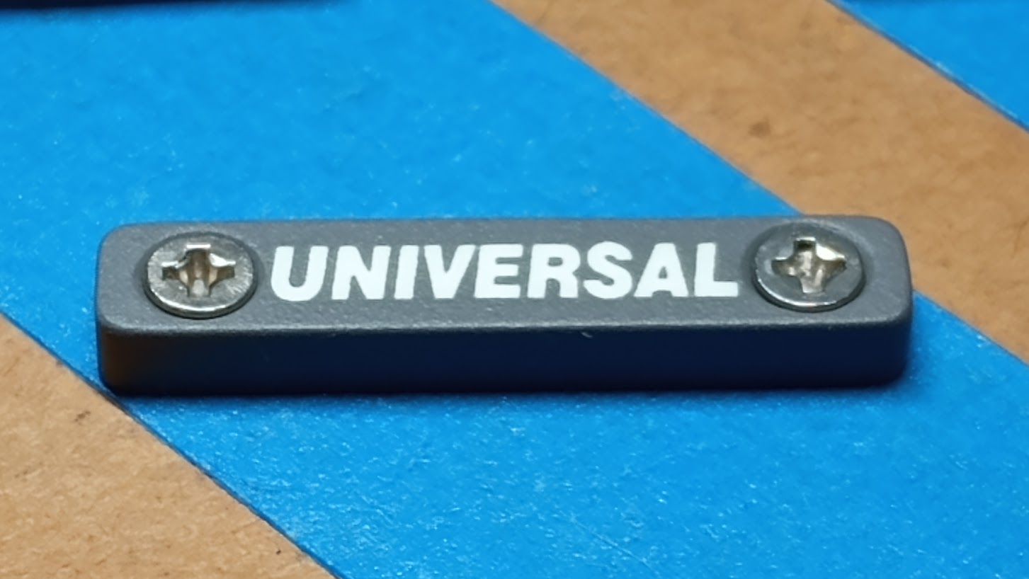
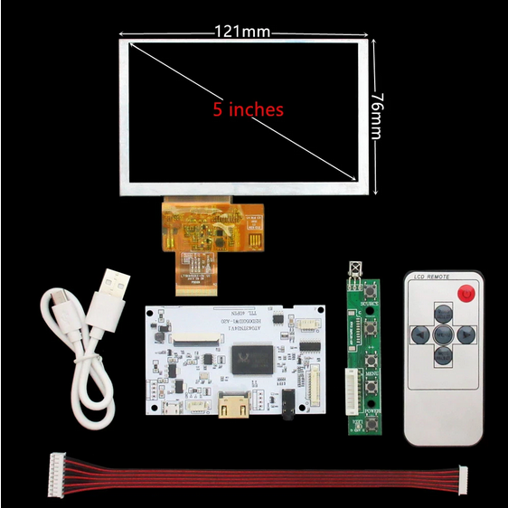
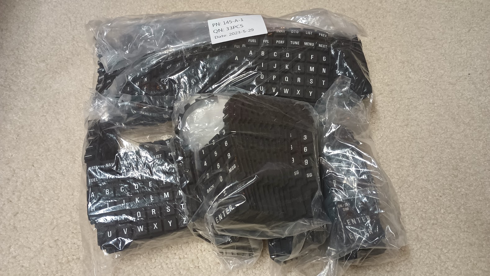
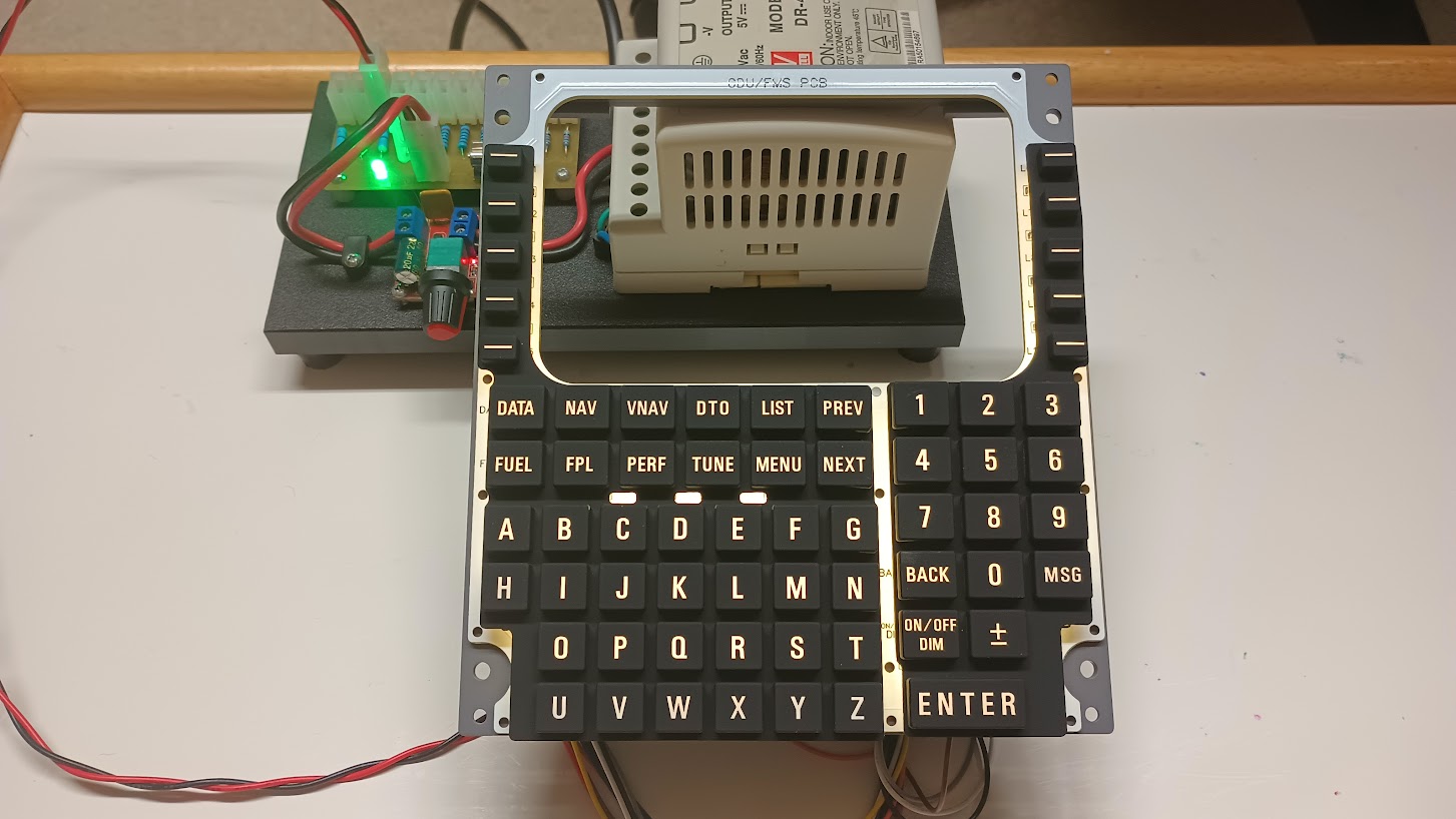
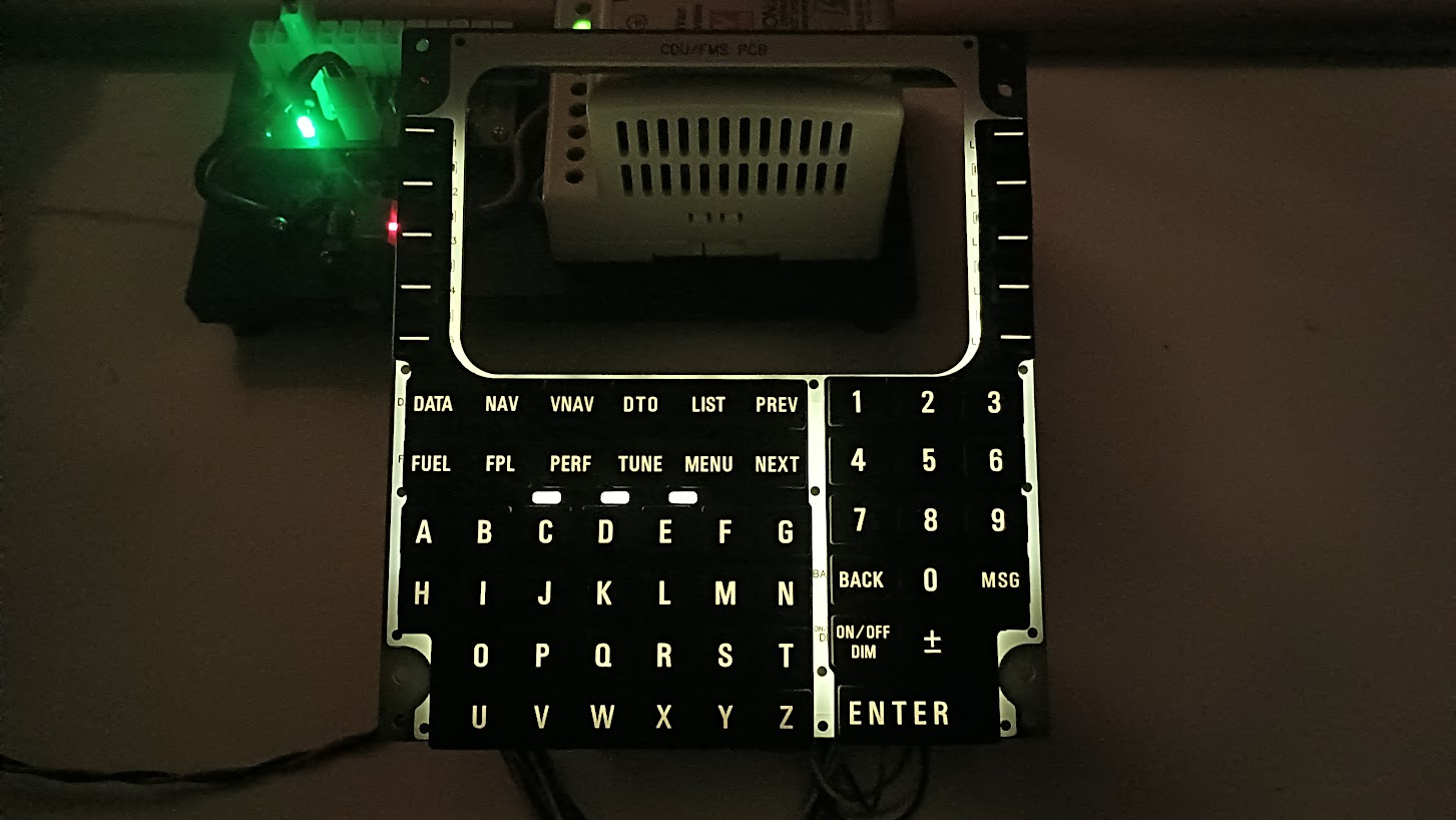
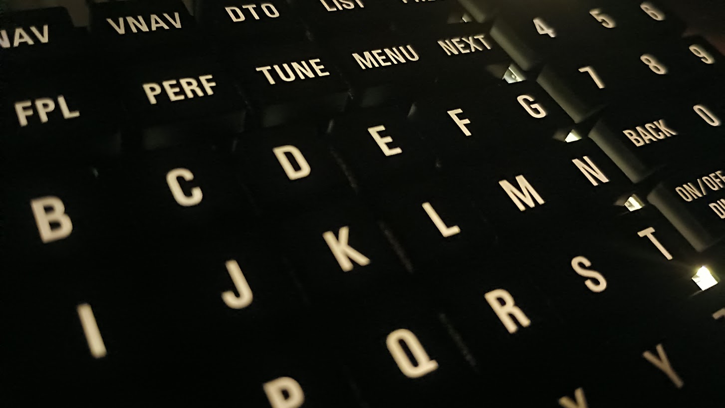
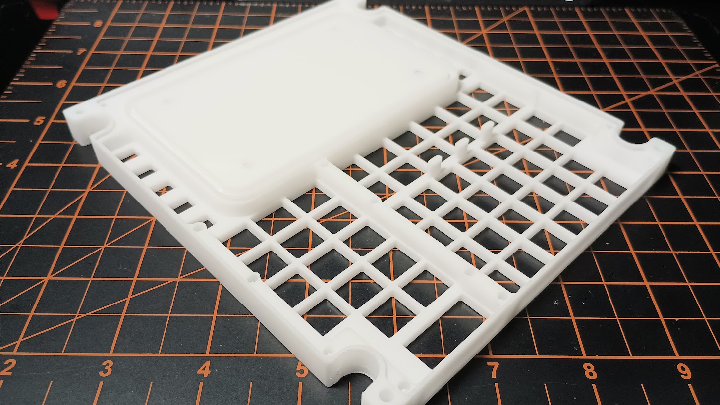
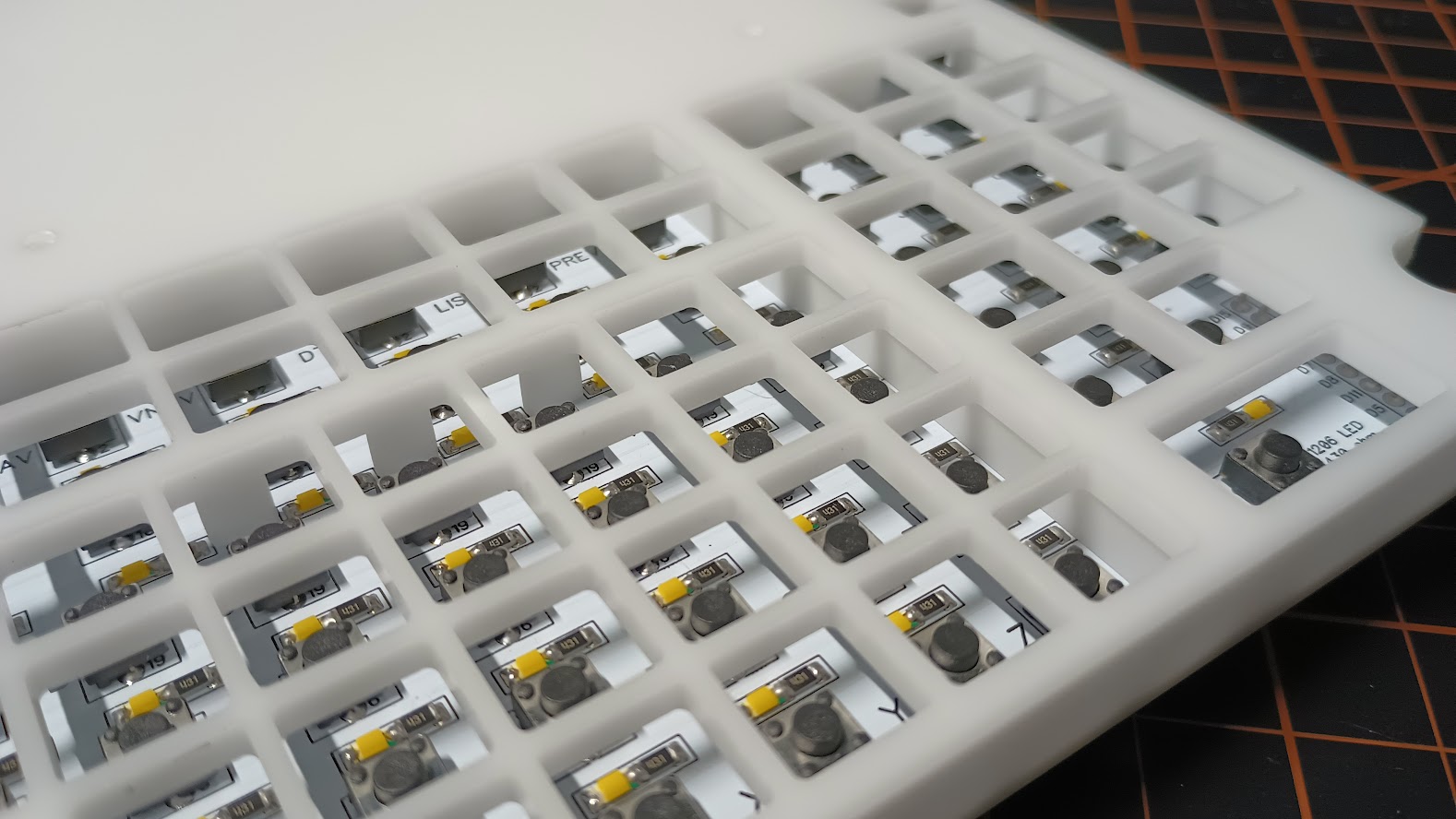
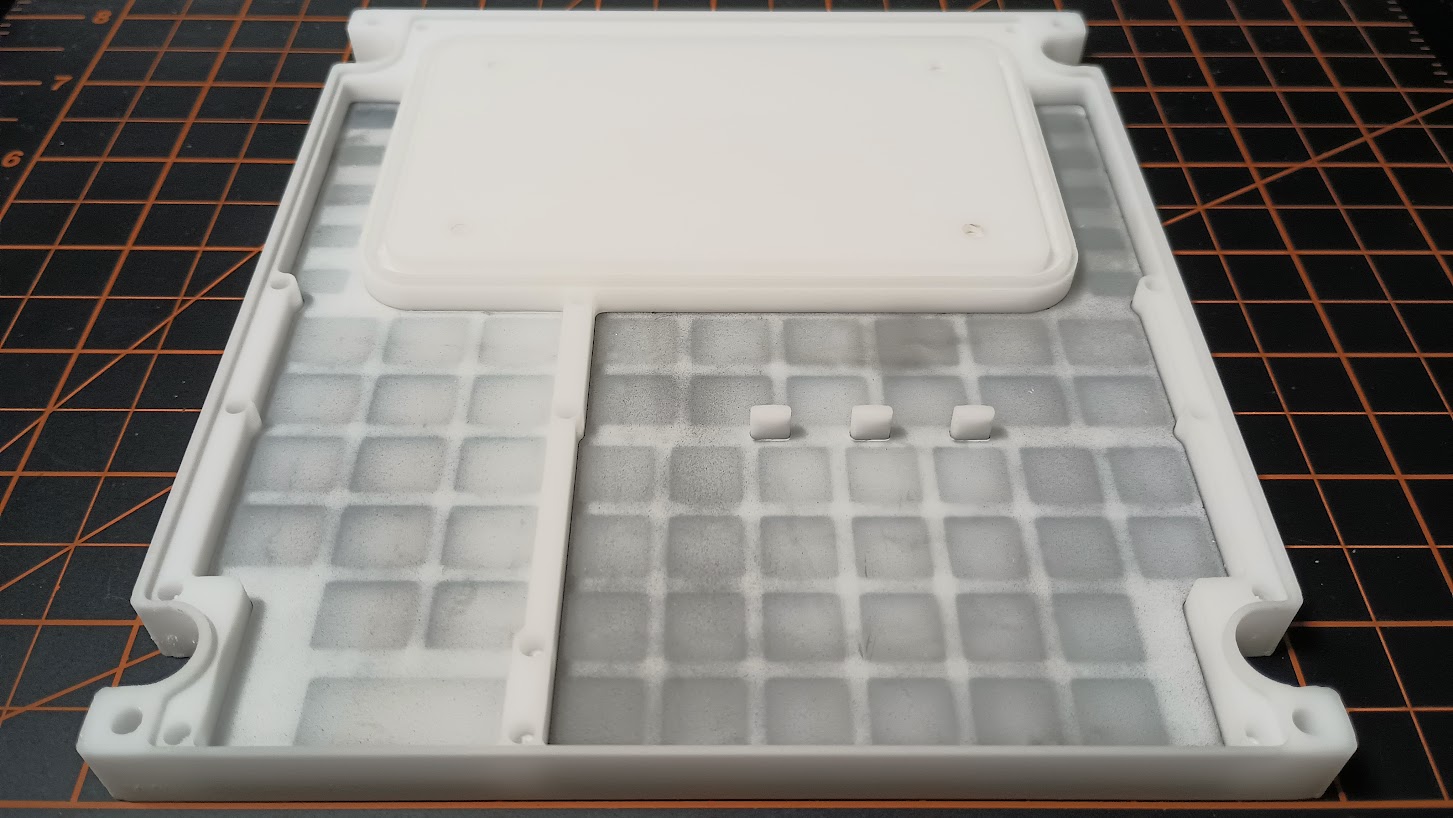
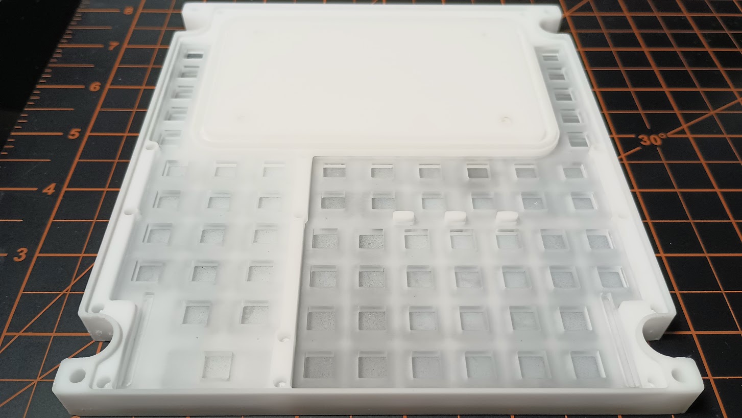
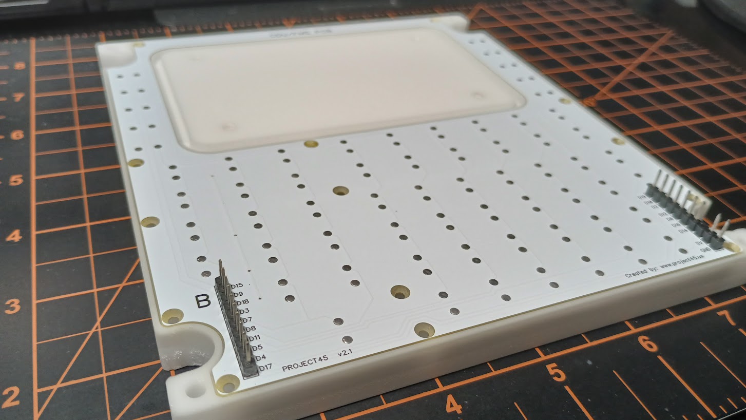
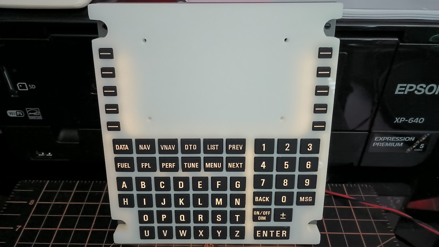
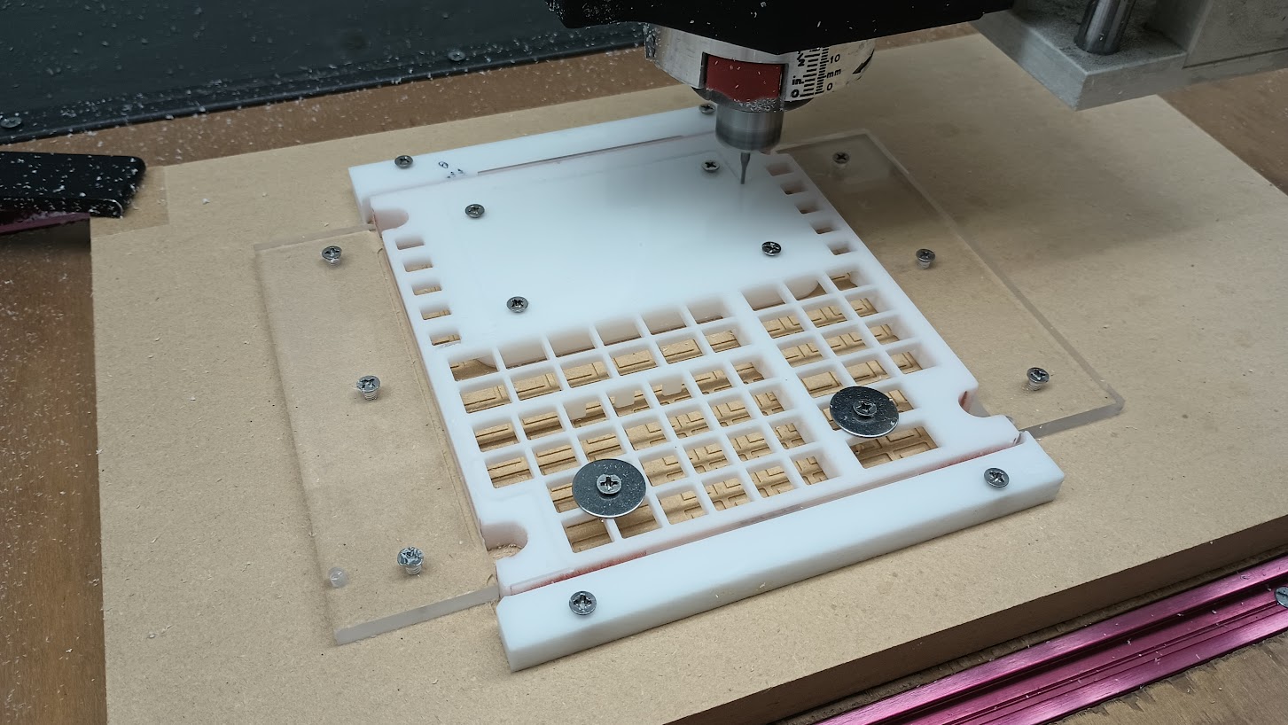
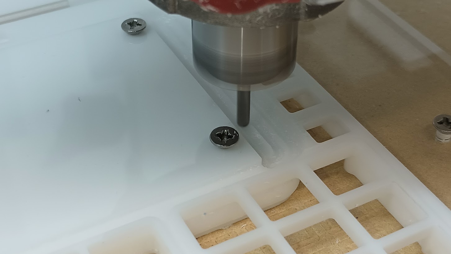
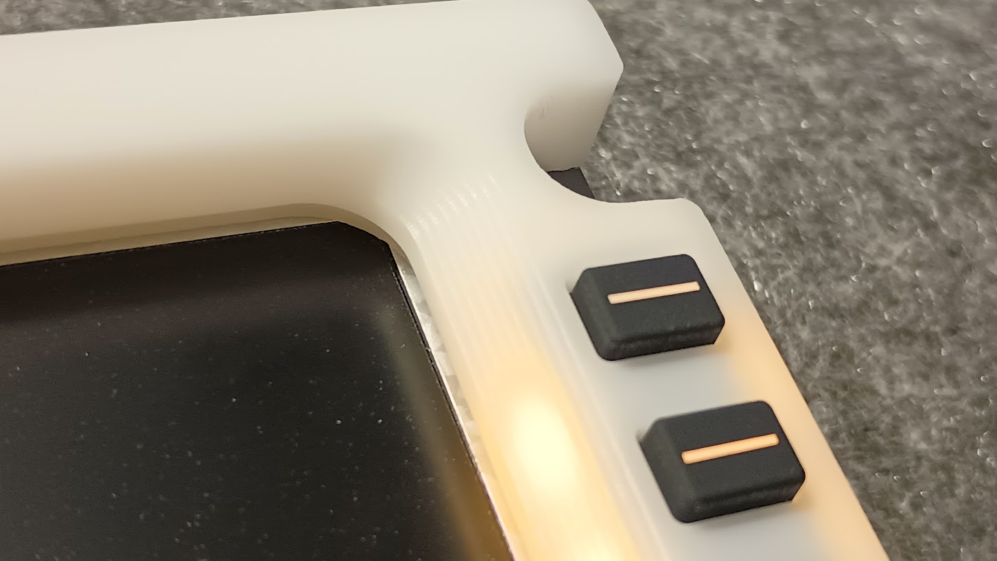
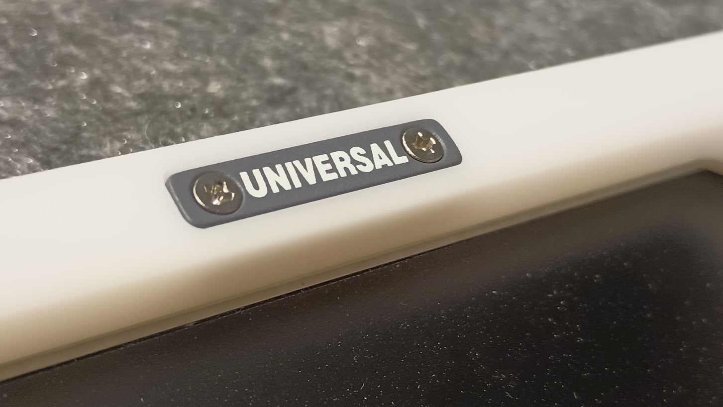
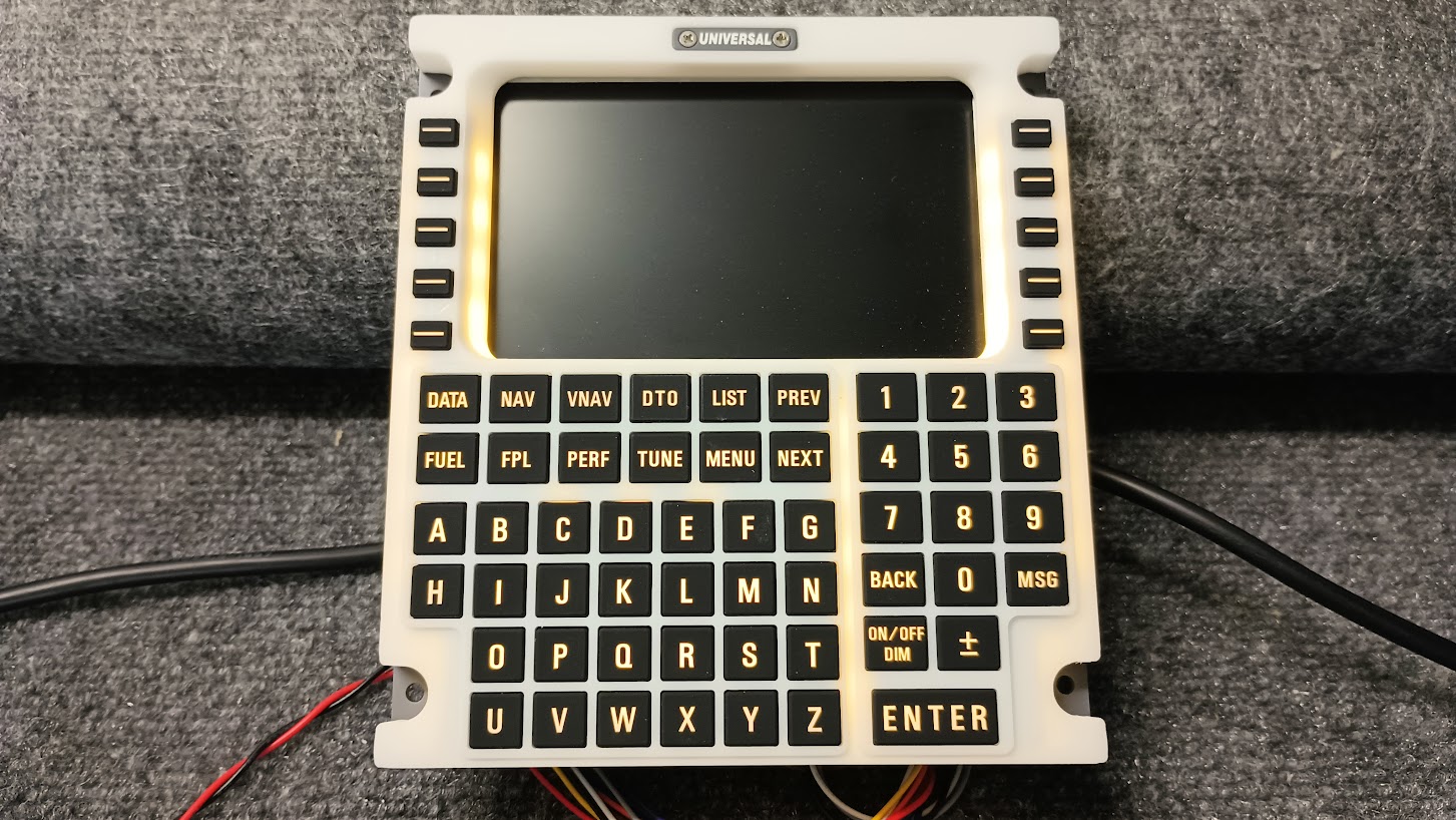
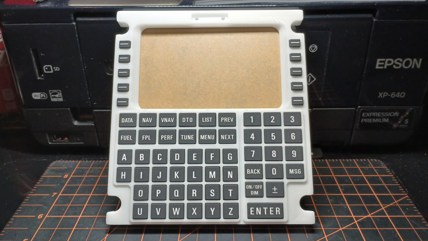
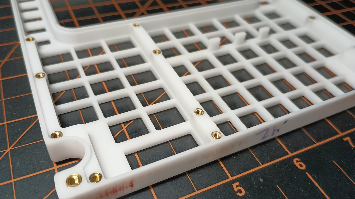
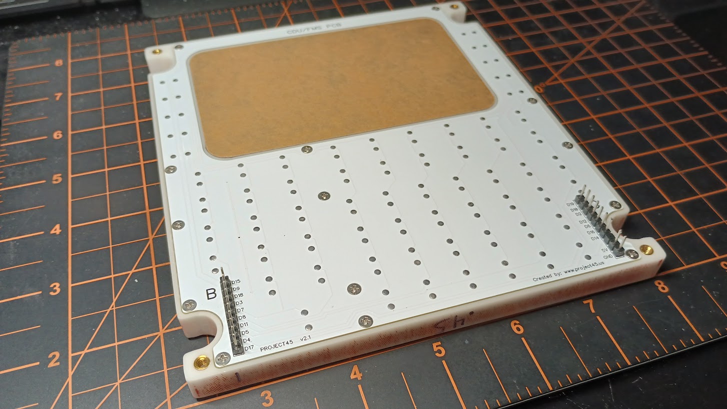
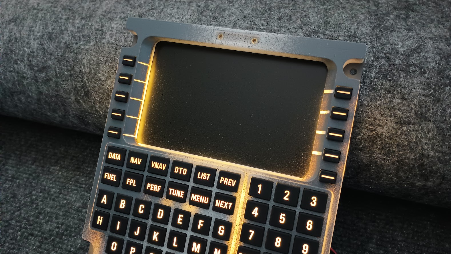
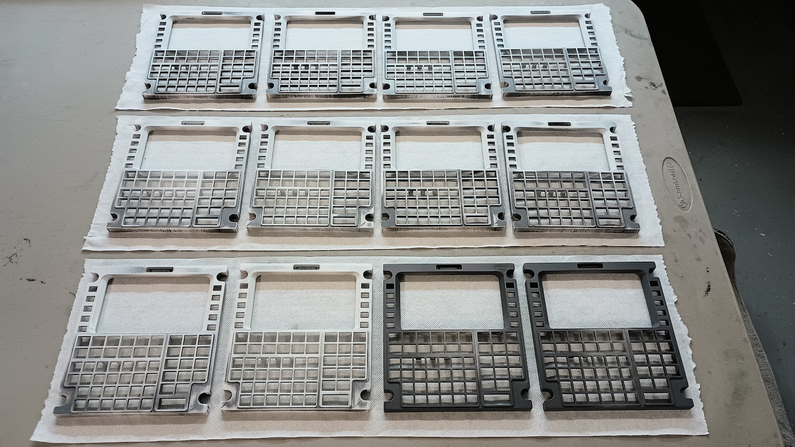
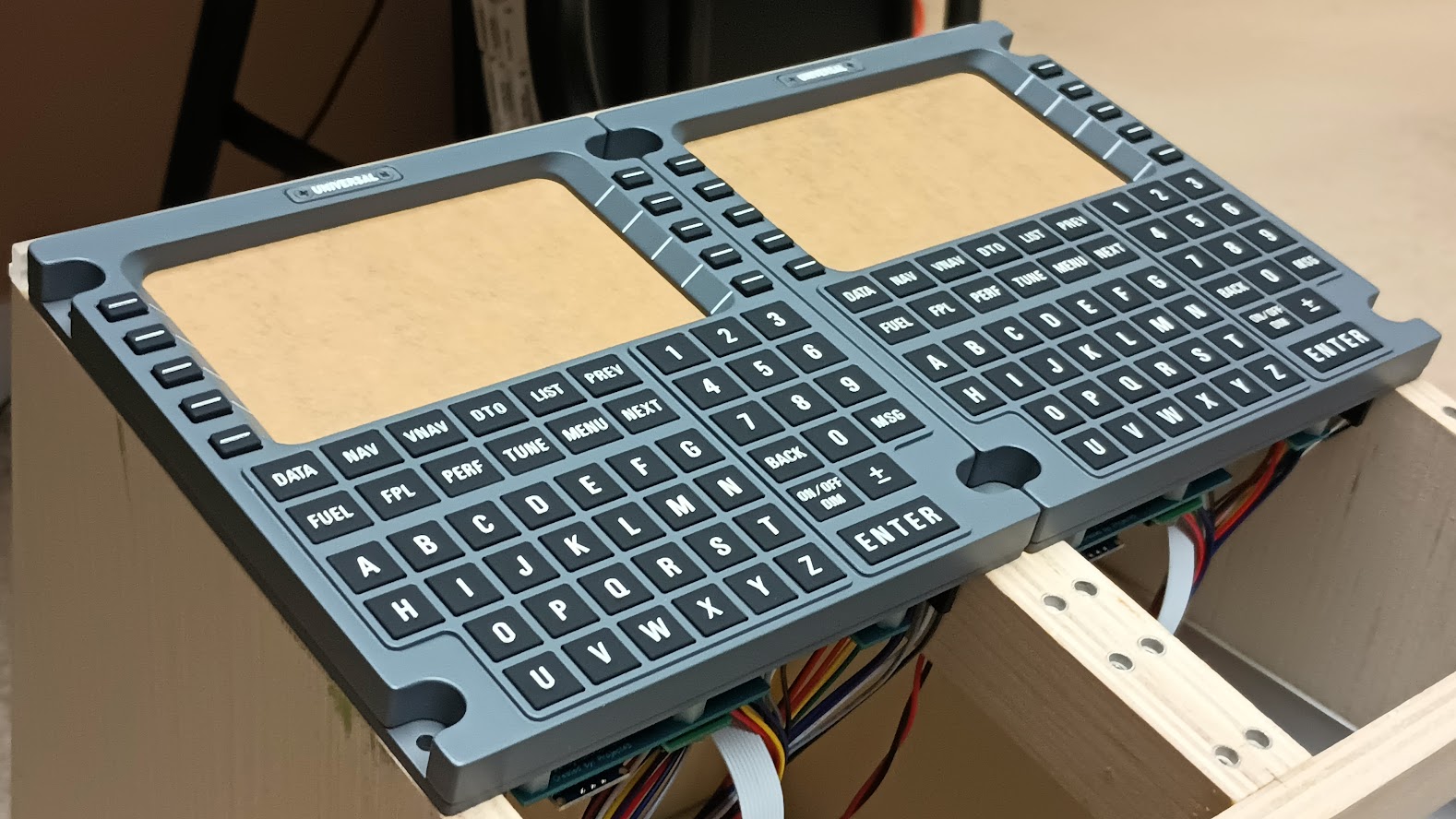
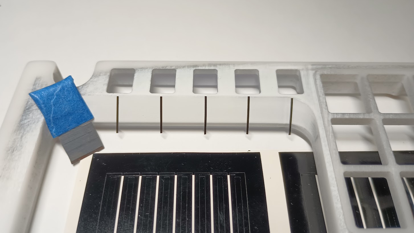
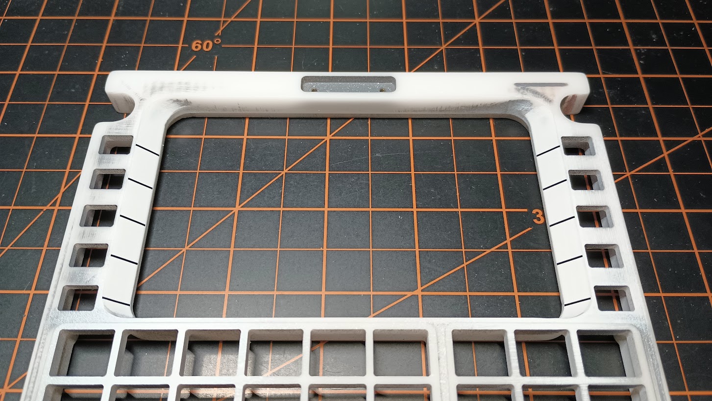
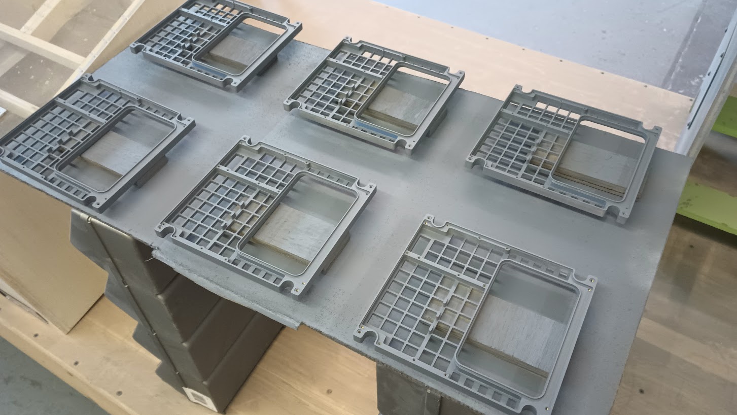
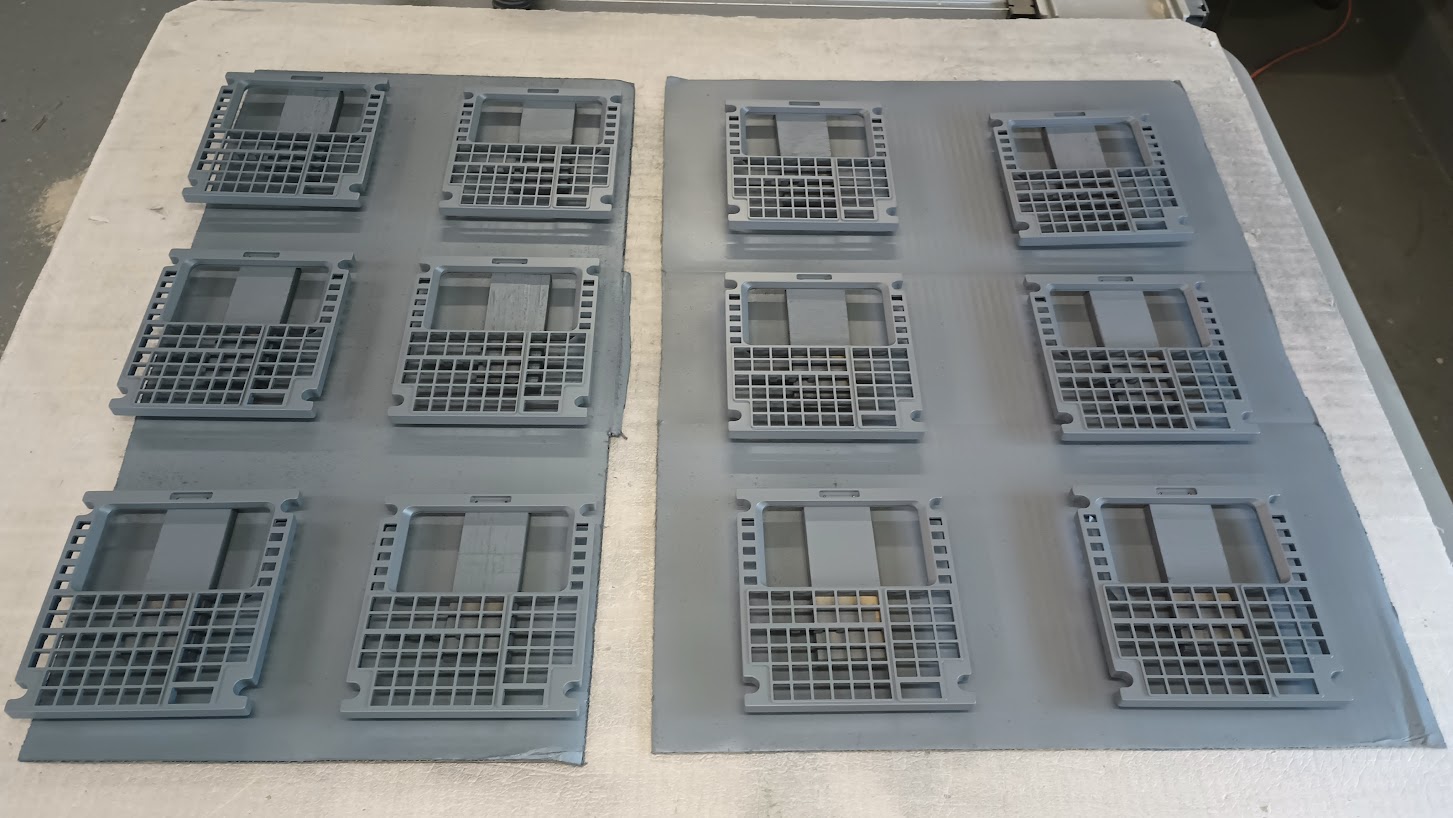
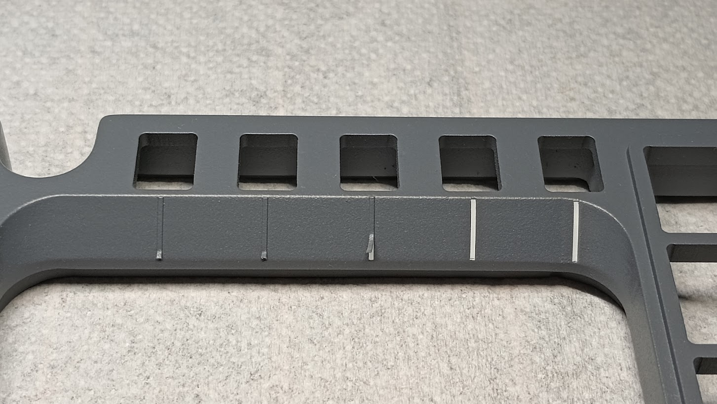
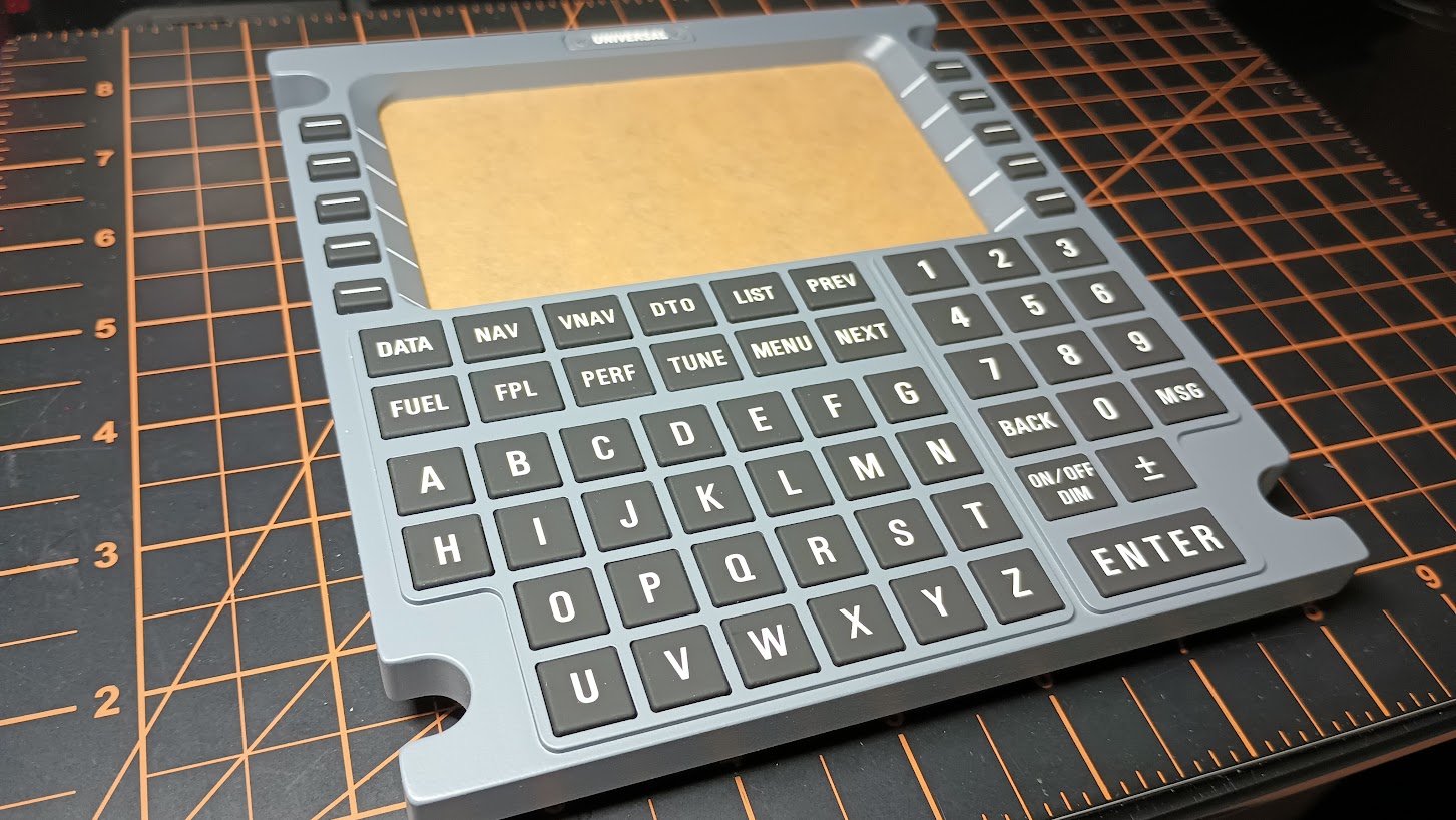
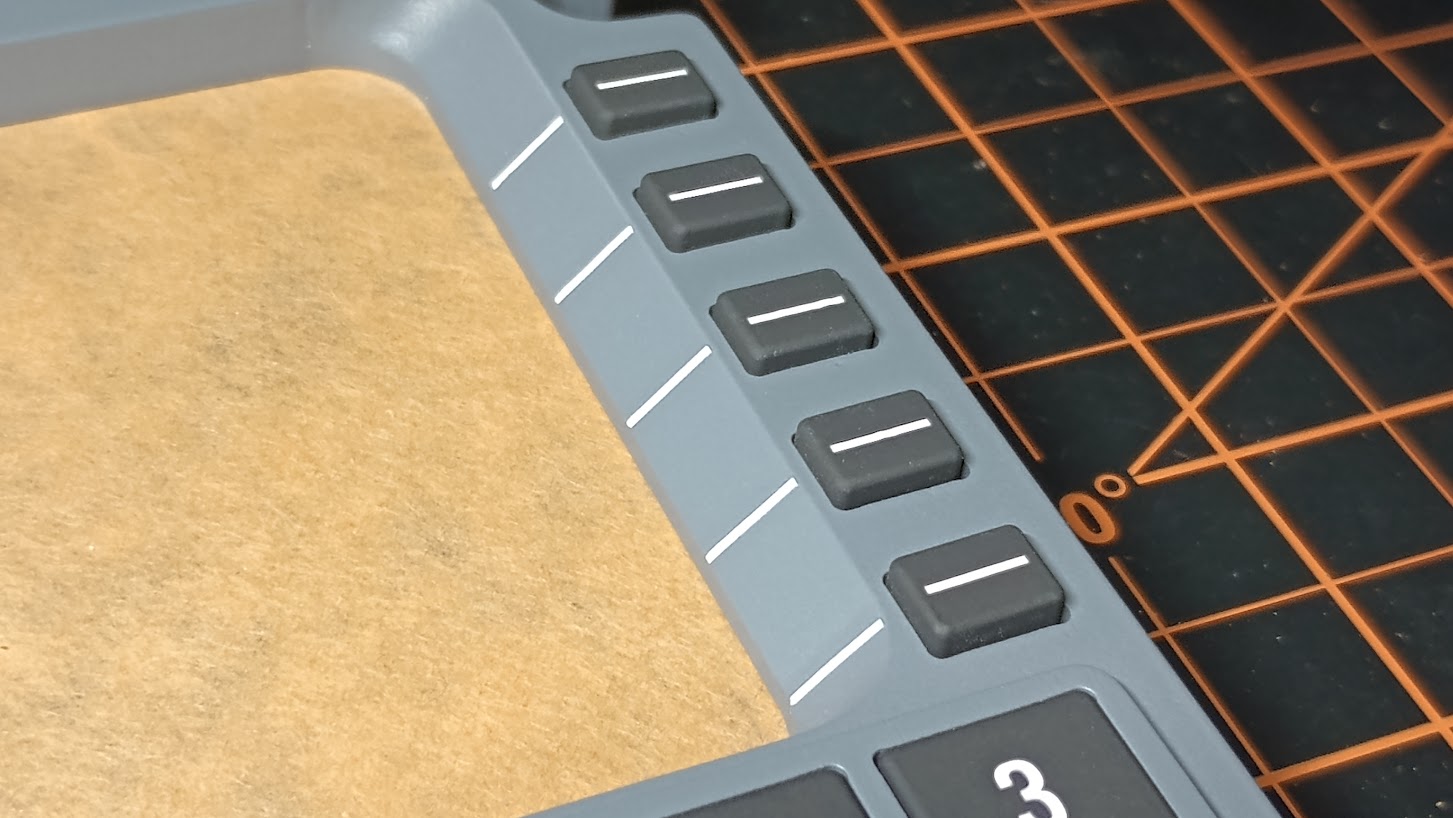
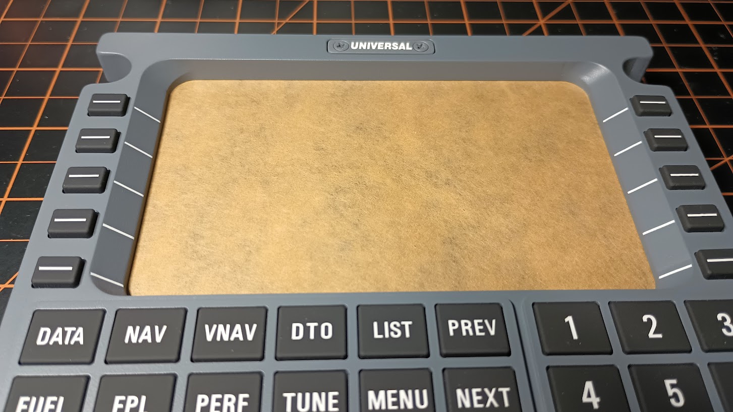
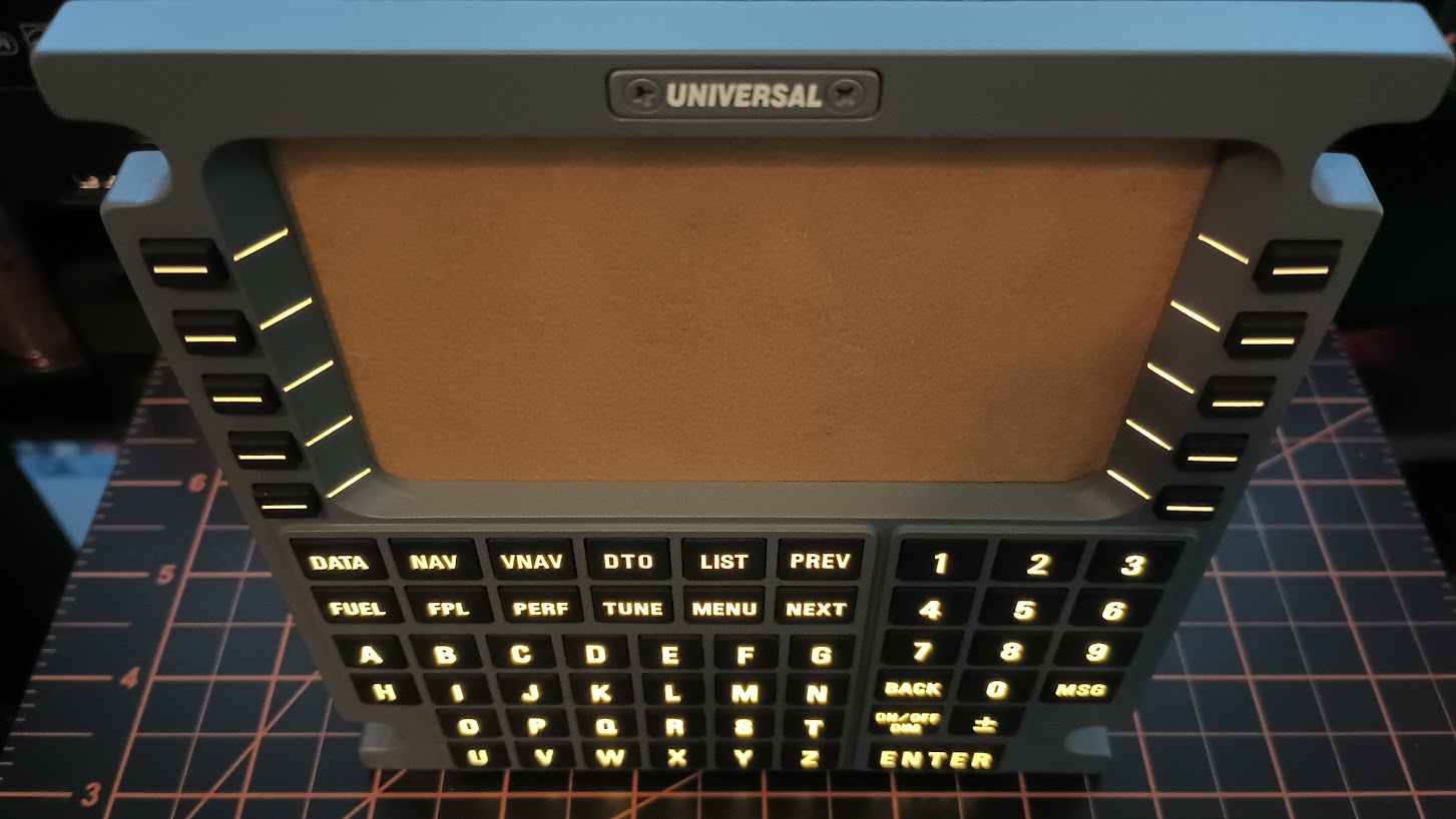
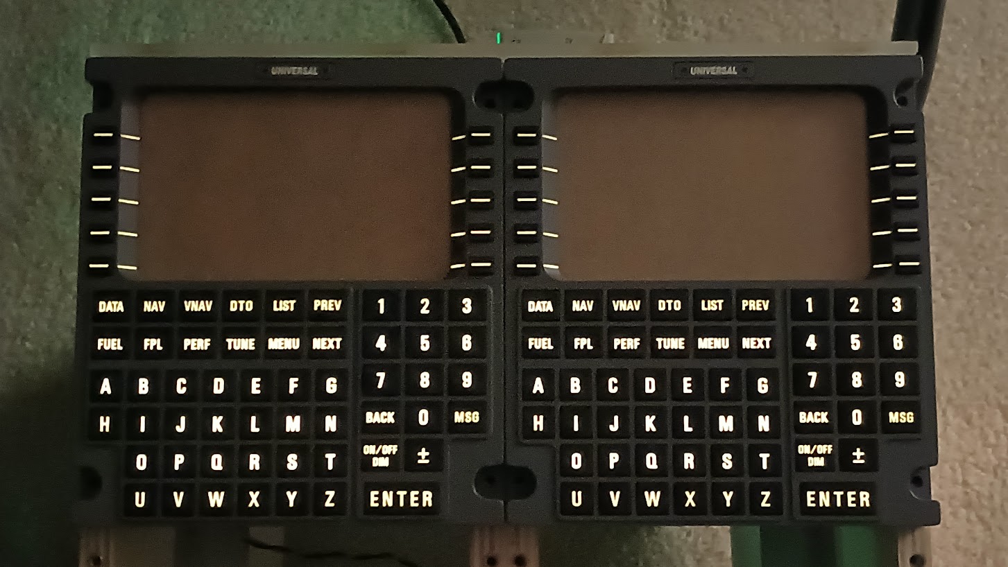
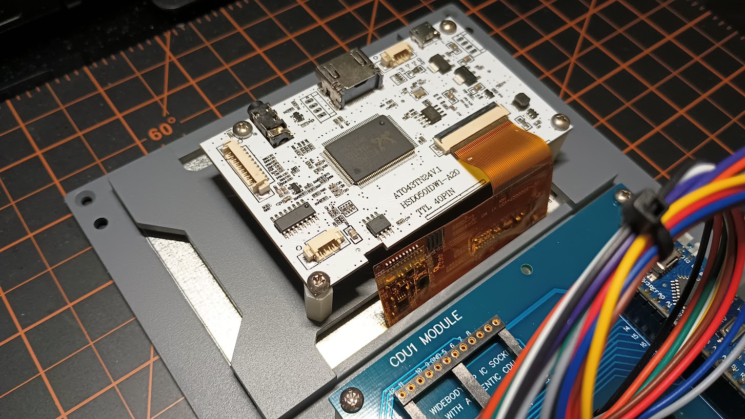
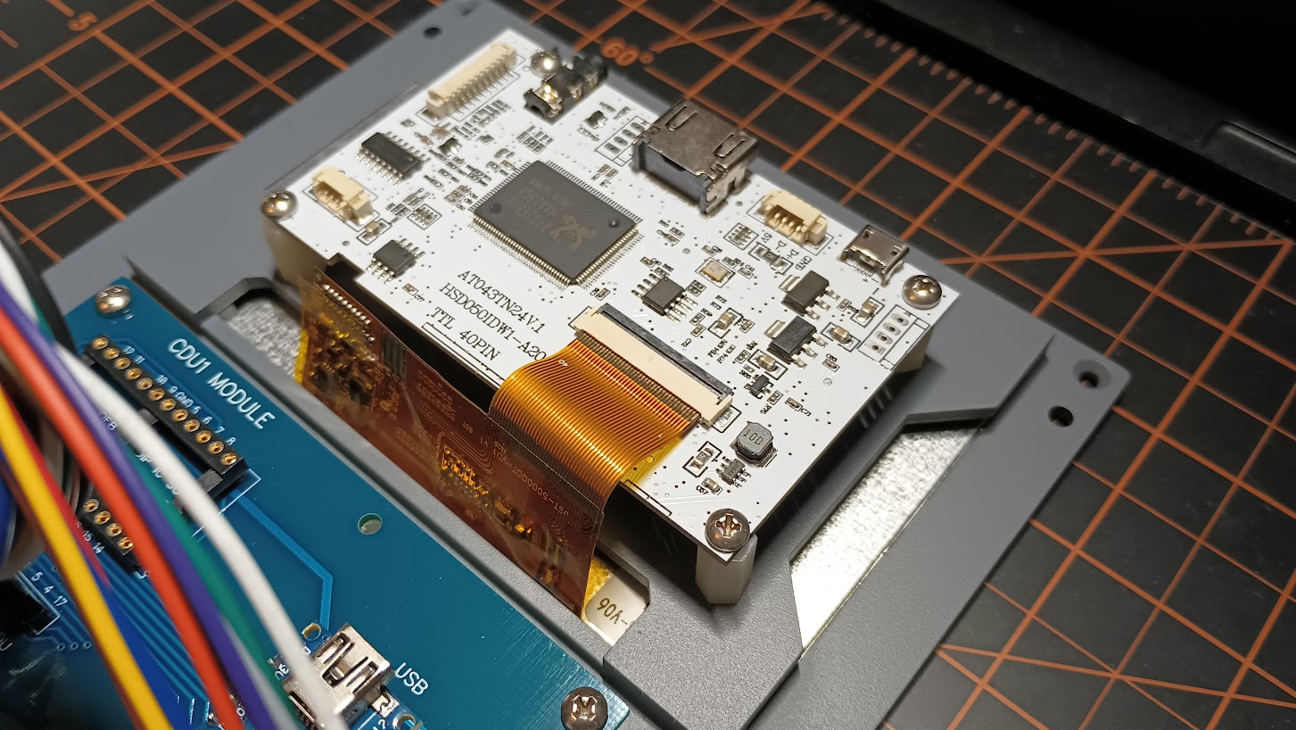
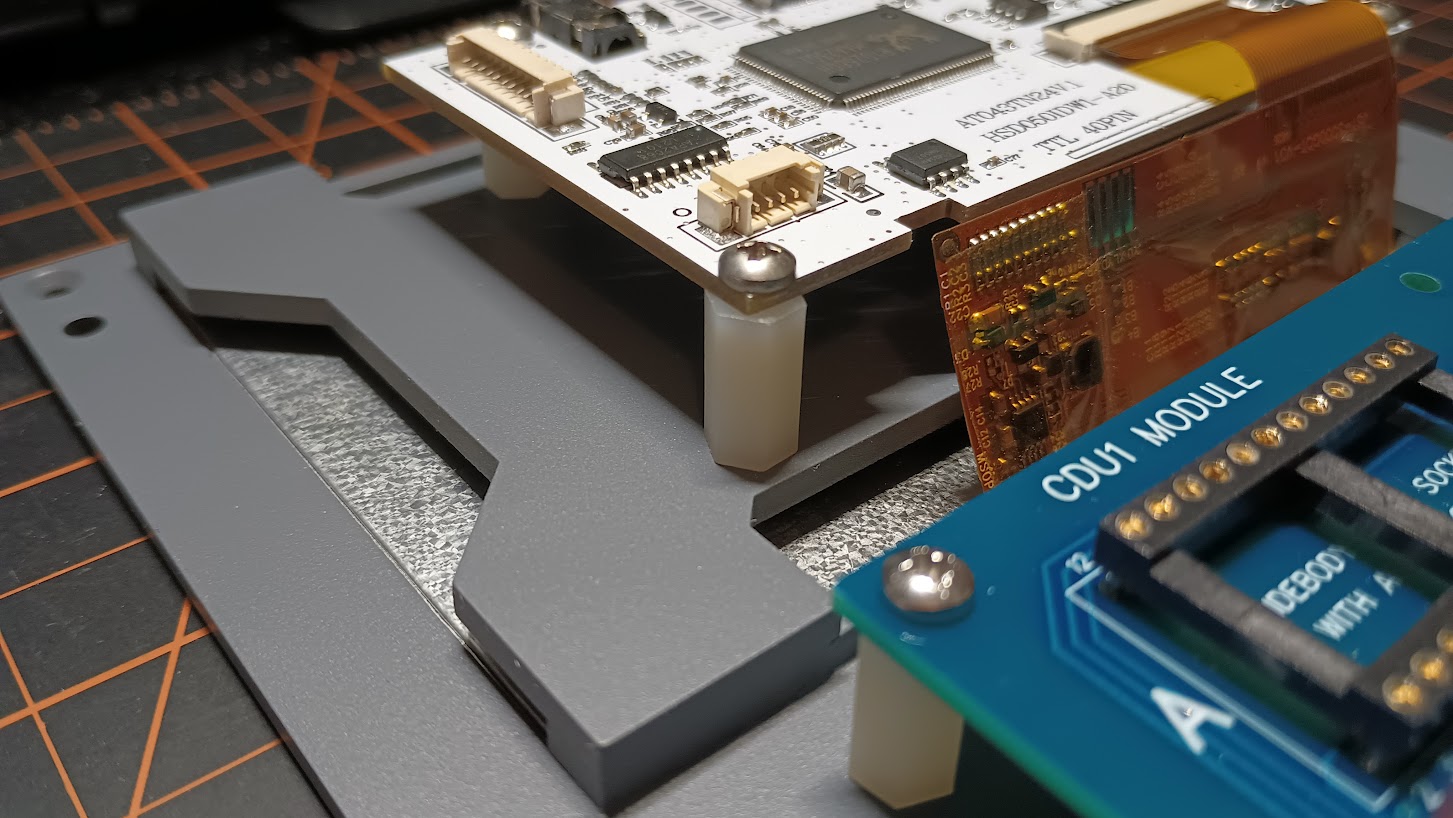
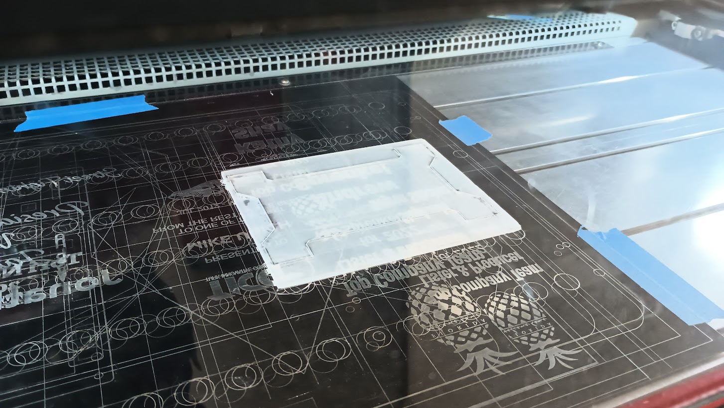
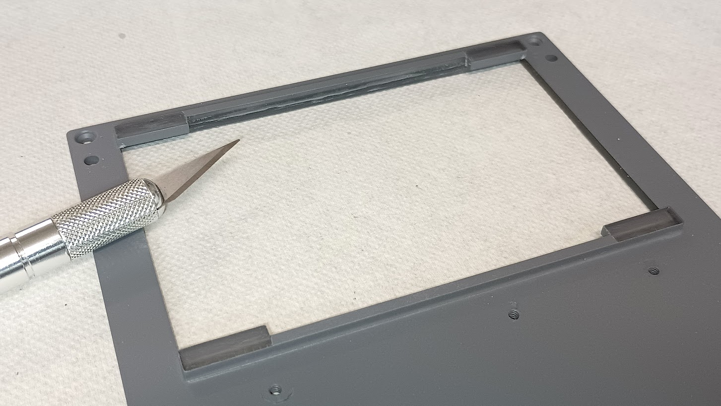
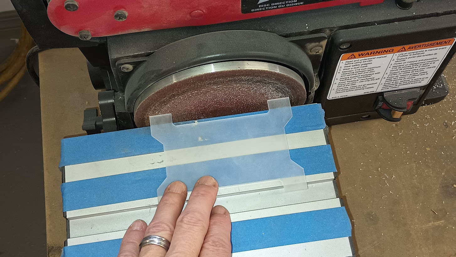
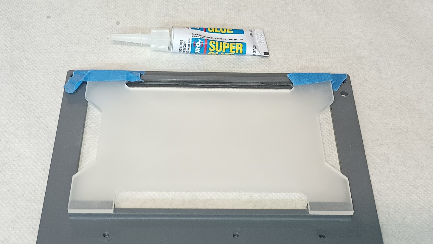
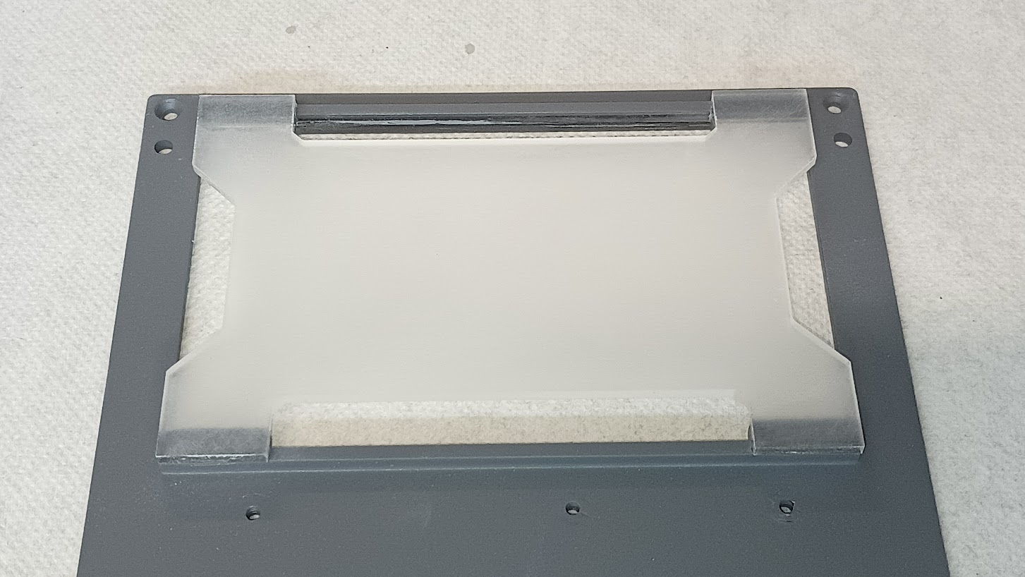
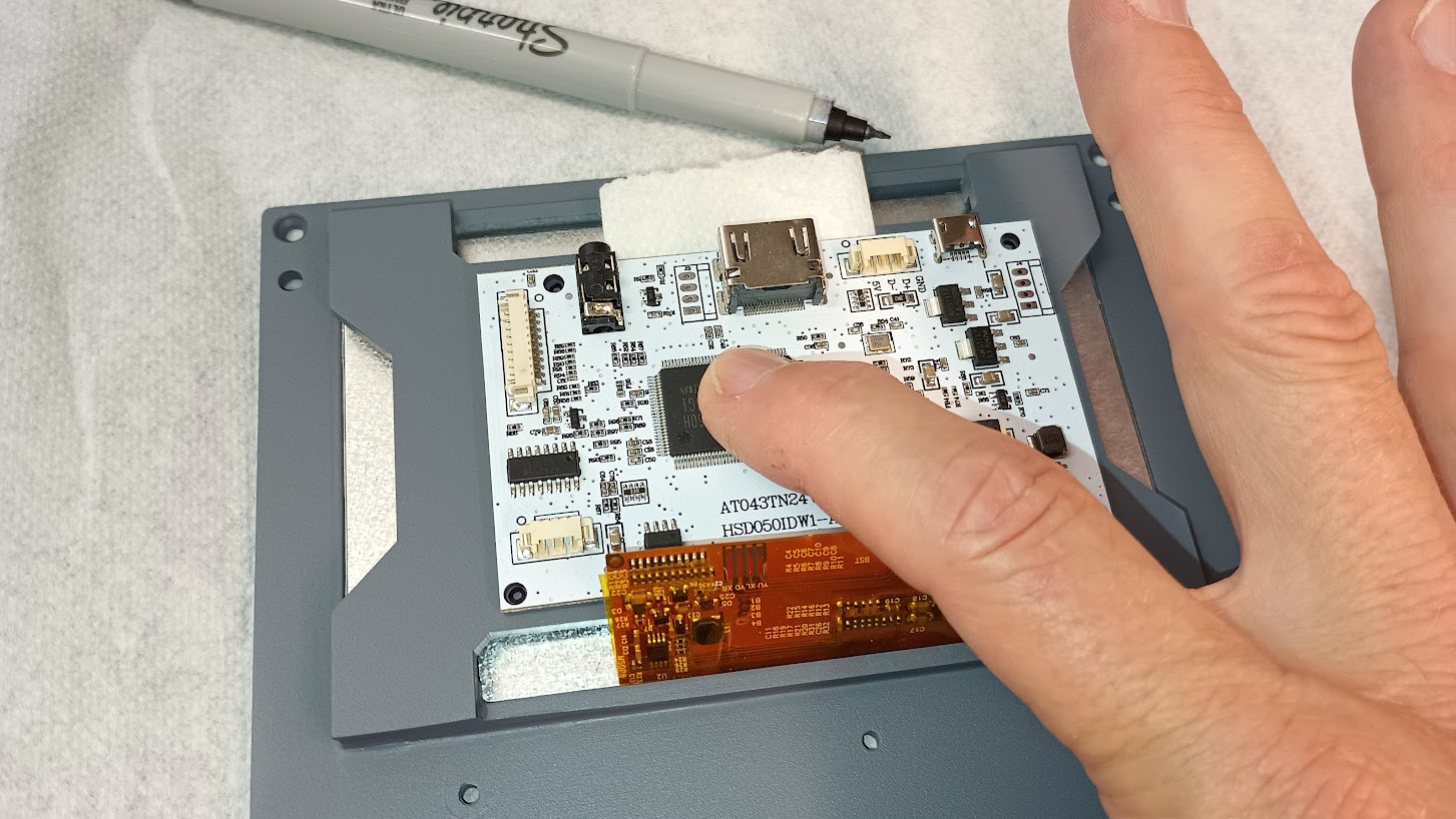
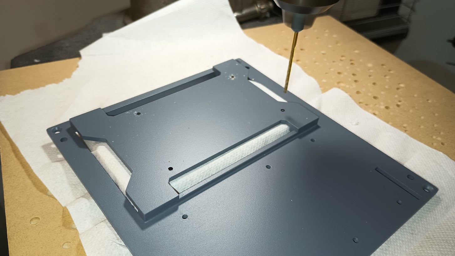
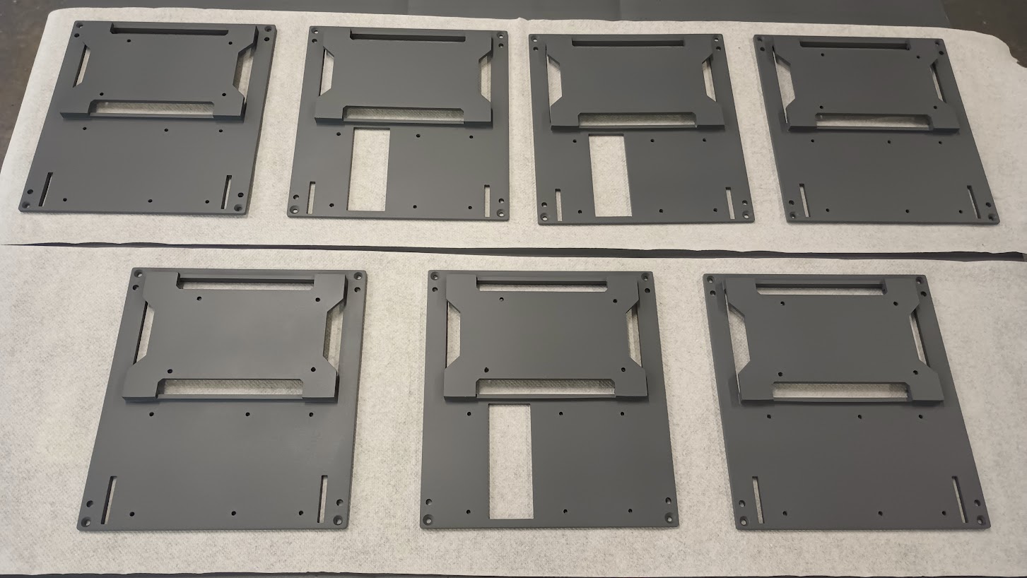
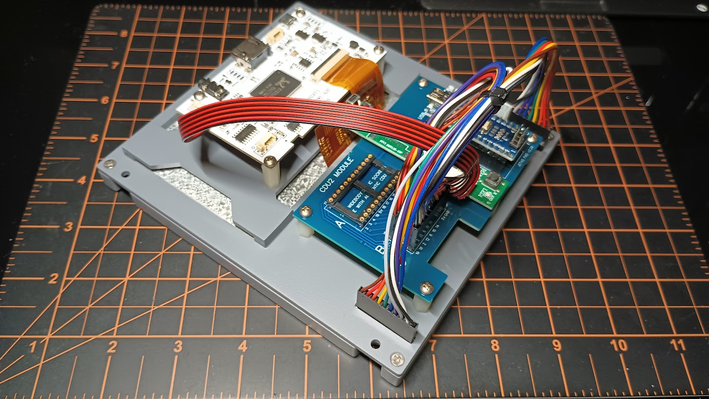
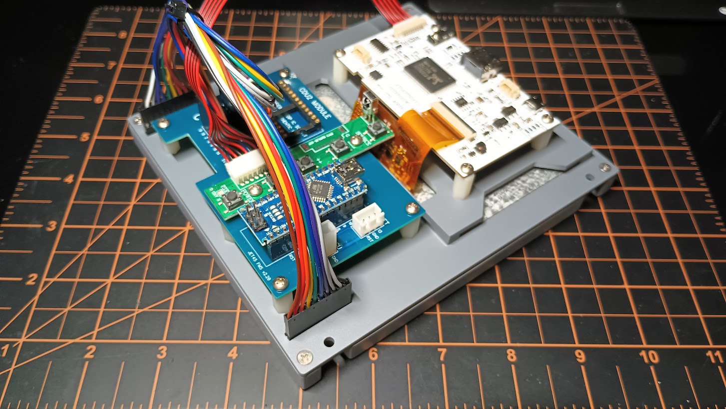
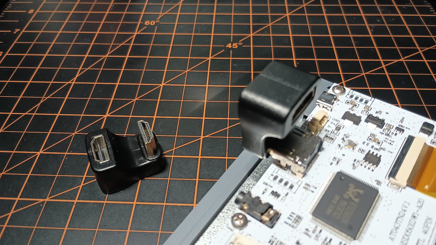
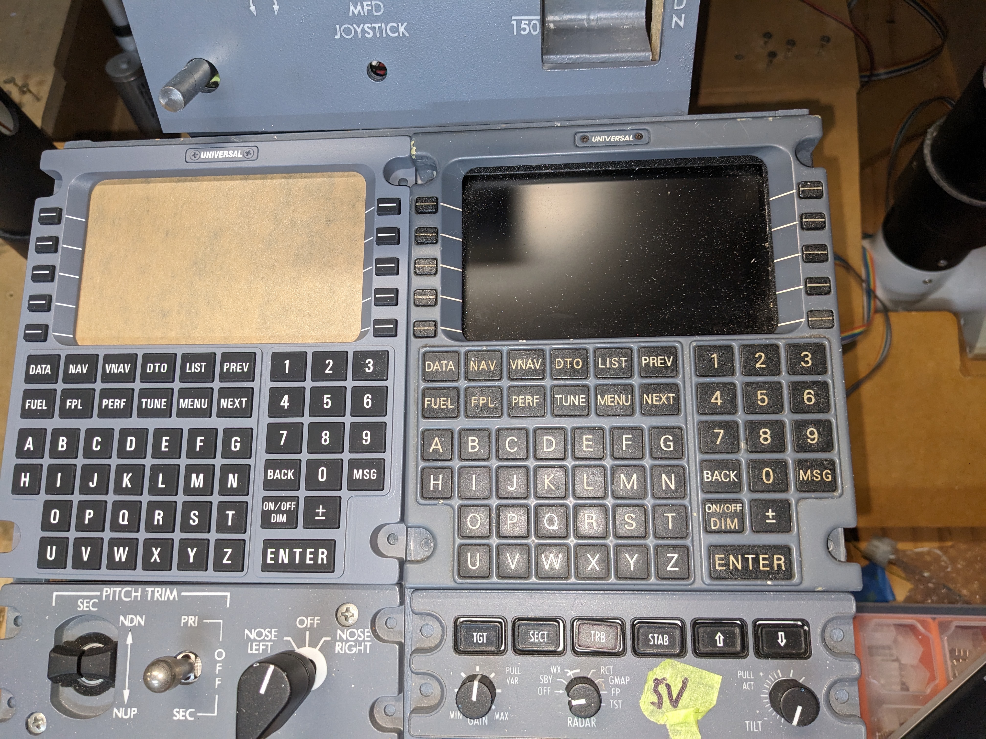
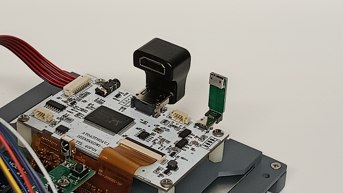
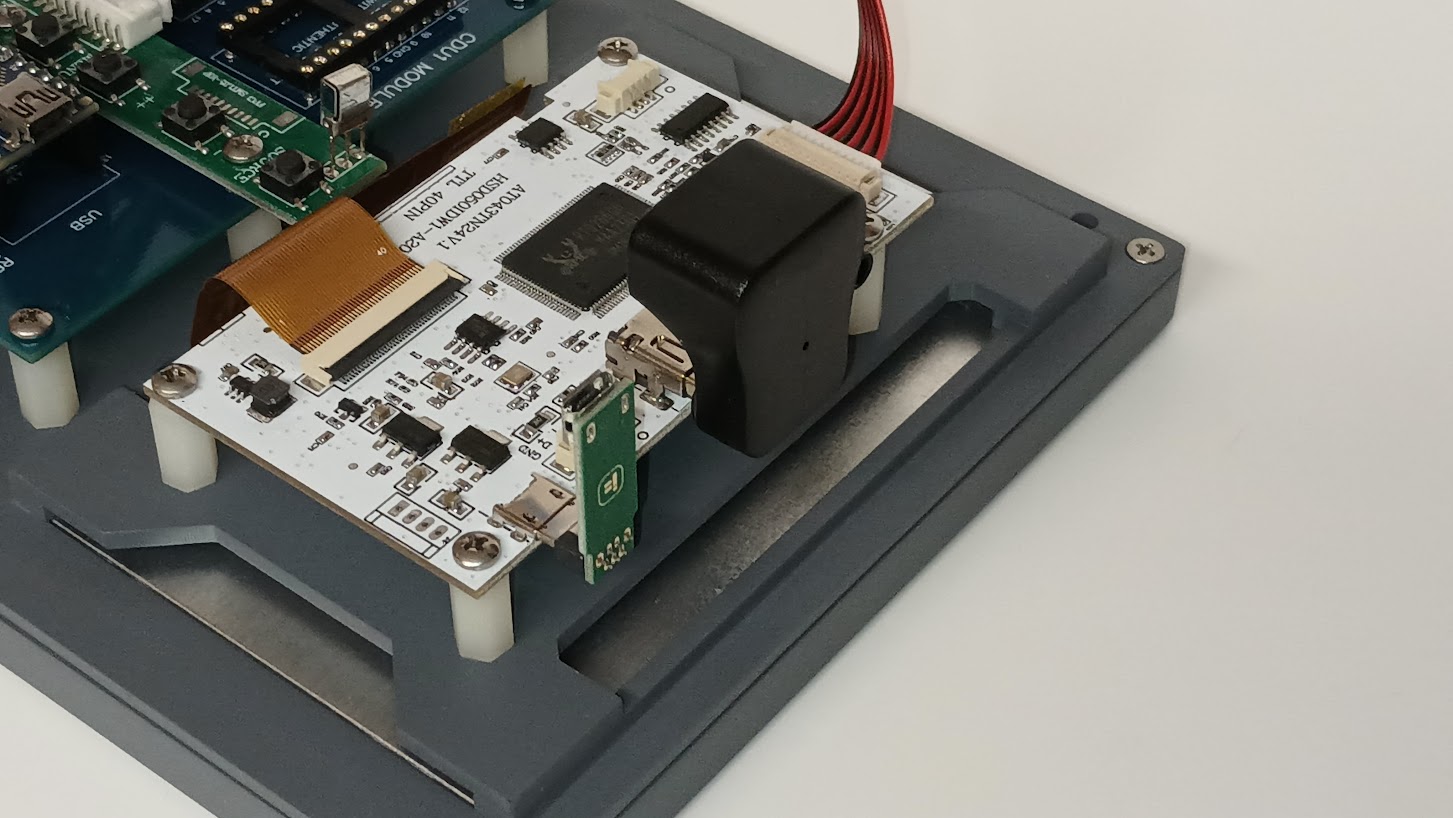
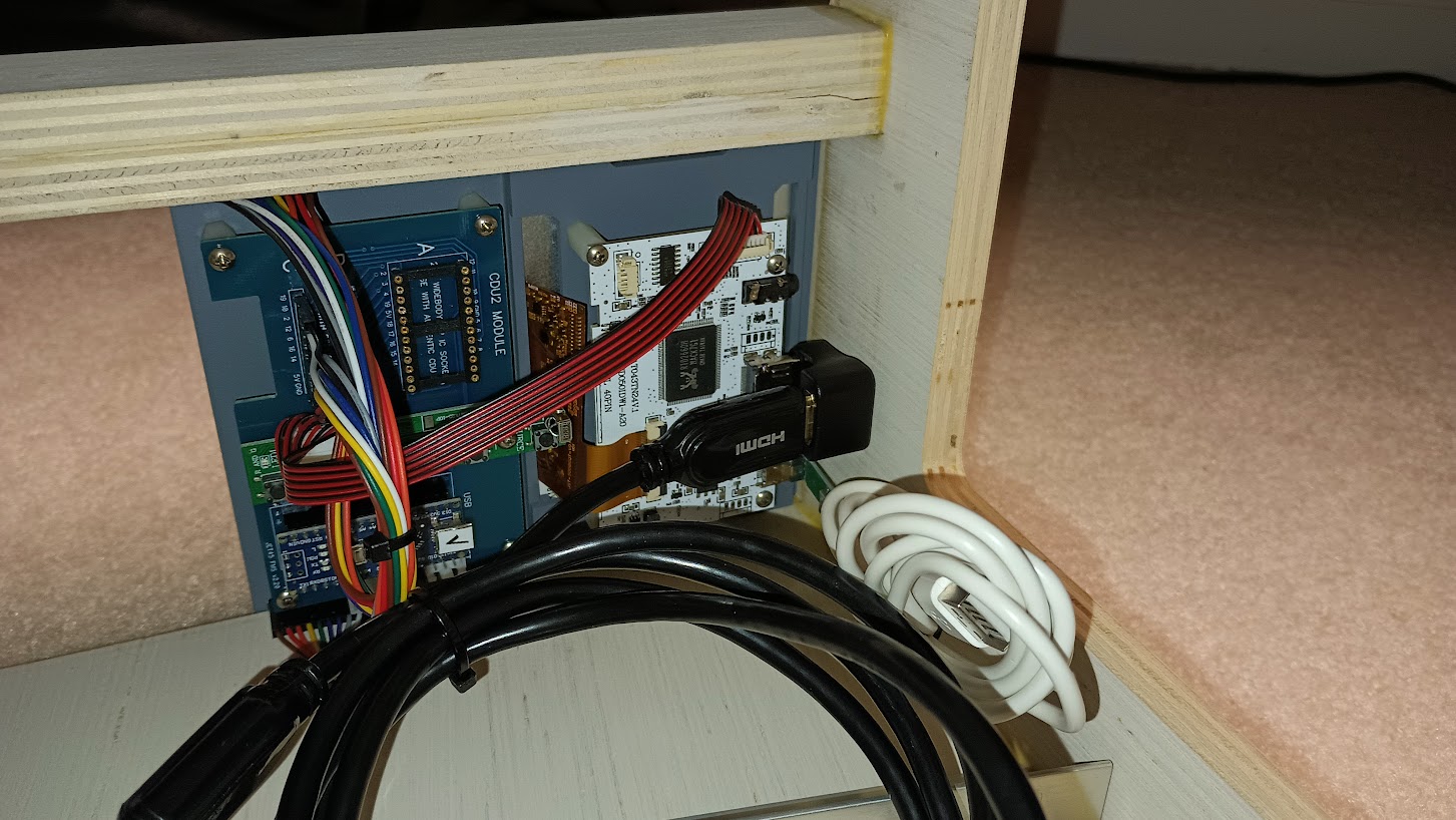
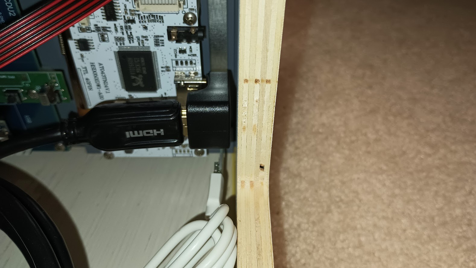
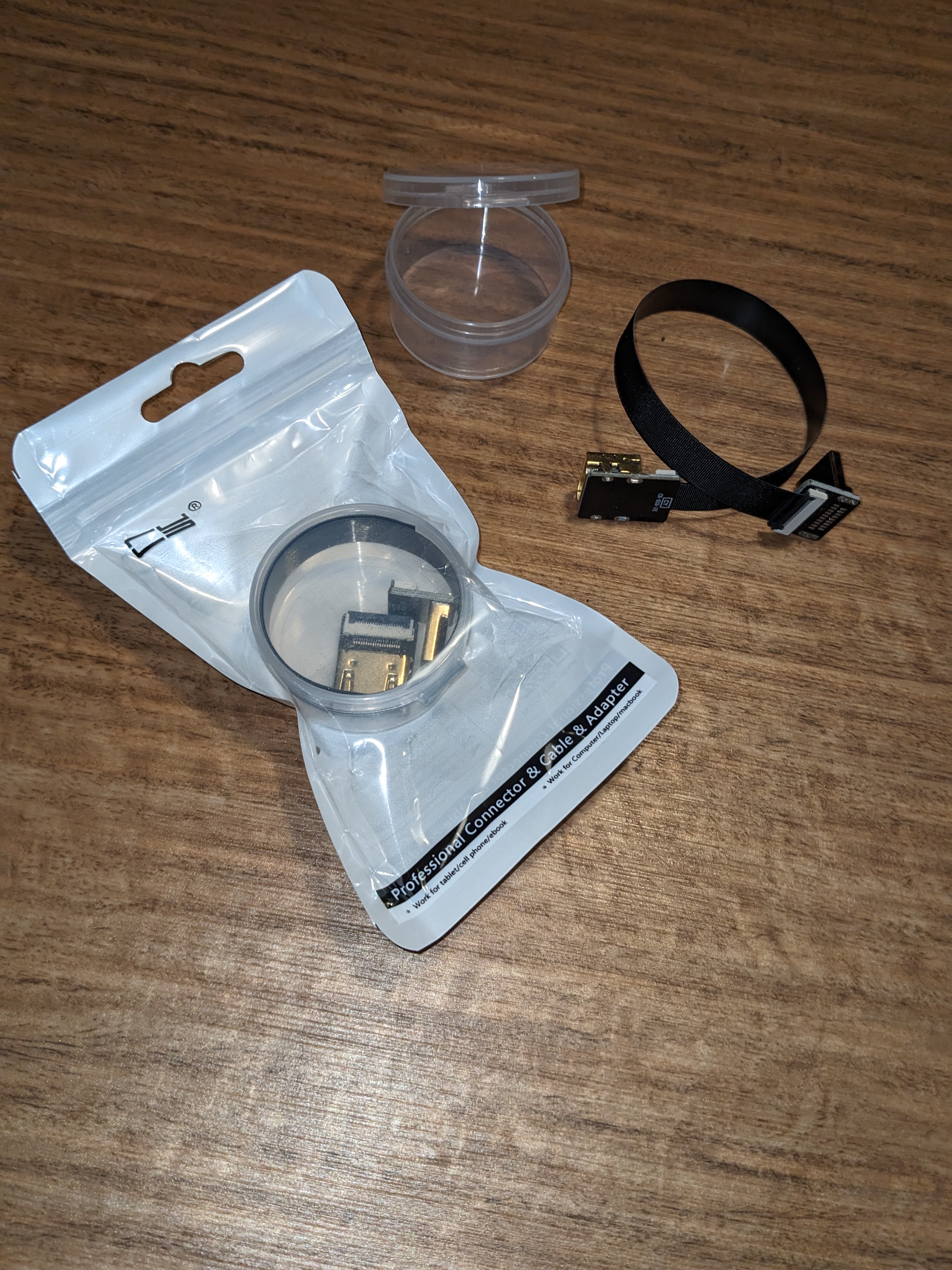
Thanks Roel! Yes, I designed the pcb and had it made. Some of the early versions of the CDU were done in multiple layers, more than two, maybe up to four. I am not sure about the newer versions, but I was able to do it in only two layers and double the amount of LEDs and also include current limiting smd resistors for each LED. Will Sasse did it in two layers and I was even able to do it using double sided copper clad. I will be making the CDU drawing publicly available once it is 100% proven, but for now, I will send you the latest version so you can see what is going on with it. Thanks Roel! Yes, I designed the pcb and had it made. Some of the early versions of the CDU were done in multiple layers, more than two, maybe up to four. I am not sure about the newer versions, but I was able to do it in only two layers and double the amount of LEDs and also include current limiting smd resistors for each LED. Will Sasse did it in two layers and I was even able to do it using double sided copper clad. I will be making the CDU drawing publicly available once it is 100% proven, but for now, I will send you the latest version so you can see what is going on with it. Hey guys, I apologize for not making an update on the UNS1 replica sooner. It's certainly not because nothing has been happening. The biggest news is the Silicone keypads are complete and should arrive in a few days. From what I have seen, they look great and I think they are going to work perfectly for our needs! A big thanks to Will Sasse for giving me a hand with the 3D modeling. We went back and forth on a couple different versions with several ideas to insure we have the best plan forward. The last thing we wanted to do is to have to do it a second time. I never needed to know how Silicone keypads were made until we decided to go this route. It briefly crossed my mind to just DIY, but if you try to research DIY Silicone keypads, there is no such thing. To do it right you need a lot of pressure and heat, not to mention a strong metal plug and mold. It did not take long to realize that if we go the Silicone keypad route, we would have to have them professionally made. Here is a short video of the biggest part of the process. https://youtu.be/7UTbKzSpezw After reaching out to several Silicone Keypad manufacturers, I finally found one that was willing to work with me in relatively small numbers and at a decent price. As you may know, the most expensive aspect to Silicone keypad manufacturing is the initial tooling. A top and bottom plug and mold has to be machine milled to perfect tolerances. This process can cost anywhere between $1,200 and $2,500 for one set of this size! But once the molds are complete, the cost per unit is between $4 and $12 depending on quantity. Obviously, the more you order, the lower the unit price falls. If we were making Vizio TV remotes, the cost would be near nothing per unit being we would need millions. But in our case, we would need no more than 50 units to get started. So as you can see, making sure that design is perfect with zero mistakes is super important because we really can't afford to have a second set of molds made. And for this reason, I am holding off on making the front panel. If there are any minor adjustments needed, they will have to be made in the front panel rather than in the keypads. In other words, the CDU is being built around the Silicone keypads. Fingers crossed they arrive just as we planned. The Silicone keypad manufacturing process is new to us all and there has been a bit of a learning curve. Not too bad though and we will be better prepared the next time we want to use Silicone keypads as a solution. In preparation of the keypads arriving, I have been very busy making as much of the CDUs as possible with the exception of the front panel which has to be milled front and back. Here is an over view of nearly 10 units ready to go! I say "better part" because apparently, I only received nine pcbs rather than the ten I ordered. No big deal, I have to place another order once the whole CDU has been proven. Along the way, I have made several improvements to the original design. First, I added tabs to hold the LCD screens in place and keep them from falling through the backer panels. Here I am test fitting a couple CDU backers in the v2.0 Center Pedestal. And here I have a couple 5 inch LCD screens sitting in the backers on the new LCD screen tabs. Perfect! In the past we had to tape the LCD screens in from the backside. Now we may only need to add some black tape to the front side to hide the LCD metal bezels. I am also going to look into making a CDU mask with the laser that acts as a barrier between the front panel and the backer. It will serve two purposes. First, it will hide the metal LCD bezels. Second, it will insulate the back side of the pcb from the front side of the backer panel. Once I get a little further along I will see if this is necessary or not. During the test fitting of the CDU backers in the Center Pedestal, I found that the inside top edge of the pedestal had to be shaved slightly. I had a second pedestal on hand and that one needed even less sanding. Your pedestal may require some sanding or none at all. Adding the new LCD screen tabs was the culprit! I wanted to document this just in case your new v2.0 CDU replicas fit a little on the tight side in the pedestal. An easy fix with an electric sanding tool and metal file. Another thing I added was an internal light plate. This will help spread and even the light through the CDU front panel. The CDU front plate is designed to be split internally to add strength, therefore, the Silicone keypads and the internal light plates are also split in two pieces. Ten sets of light plates and smoked lenses ready to go all cut with the newly acquired laser! And here is a close up of one of the backers ready to go with the CDU module installed. Another neat detail to the new v2.0 UNS1 CDUs is the UNIVERSAL plate that is mounted at the top of the panel. I used dry transfers for the artwork. You will never look at this piece any closer than this! The plate is held in place with two 2-56 counter sink screws. I also have several 5 inch LCD screens ordered which will be here in a few weeks. The upgrade from previous versions is they will have an HDMI socket rather than a VGA socket. They also have an external pcb control panel for adjusting the brightness and contrast. The fit will be exactly the same as the previous version so no modifications needed. Another update soon once the Silicone keypads arrive in a few days. In the meantime it feels good not having anything to do on the CDUs for a couple days! Hey guys, I apologize for not making an update on the UNS1 replica sooner. It's certainly not because nothing has been happening. The biggest news is the Silicone keypads are complete and should arrive in a few days. From what I have seen, they look great and I think they are going to work perfectly for our needs! A big thanks to Will Sasse for giving me a hand with the 3D modeling. We went back and forth on a couple different versions with several ideas to insure we have the best plan forward. The last thing we wanted to do is to have to do it a second time. I never needed to know how Silicone keypads were made until we decided to go this route. It briefly crossed my mind to just DIY, but if you try to research DIY Silicone keypads, there is no such thing. To do it right you need a lot of pressure and heat, not to mention a strong metal plug and mold. It did not take long to realize that if we go the Silicone keypad route, we would have to have them professionally made. Here is a short video of the biggest part of the process. After reaching out to several Silicone Keypad manufacturers, I finally found one that was willing to work with me in relatively small numbers and at a decent price. As you may know, the most expensive aspect to Silicone keypad manufacturing is the initial tooling. A top and bottom plug and mold has to be machine milled to perfect tolerances. This process can cost anywhere between $1,200 and $2,500 for one set of this size! But once the molds are complete, the cost per unit is between $4 and $12 depending on quantity. Obviously, the more you order, the lower the unit price falls. If we were making Vizio TV remotes, the cost would be near nothing per unit being we would need millions. But in our case, we would need no more than 50 units to get started. So as you can see, making sure that design is perfect with zero mistakes is super important because we really can't afford to have a second set of molds made. And for this reason, I am holding off on making the front panel. If there are any minor adjustments needed, they will have to be made in the front panel rather than in the keypads. In other words, the CDU is being built around the Silicone keypads. Fingers crossed they arrive just as we planned. The Silicone keypad manufacturing process is new to us all and there has been a bit of a learning curve. Not too bad though and we will be better prepared the next time we want to use Silicone keypads as a solution. In preparation of the keypads arriving, I have been very busy making as much of the CDUs as possible with the exception of the front panel which has to be milled front and back. Here is an over view of nearly 10 units ready to go! I say "better part" because apparently, I only received nine pcbs rather than the ten I ordered. No big deal, I have to place another order once the whole CDU has been proven. Along the way, I have made several improvements to the original design. First, I added tabs to hold the LCD screens in place and keep them from falling through the backer panels. Here I am test fitting a couple CDU backers in the v2.0 Center Pedestal. And here I have a couple 5 inch LCD screens sitting in the backers on the new LCD screen tabs. Perfect! In the past we had to tape the LCD screens in from the backside. Now we may only need to add some black tape to the front side to hide the LCD metal bezels. I am also going to look into making a CDU mask with the laser that acts as a barrier between the front panel and the backer. It will serve two purposes. First, it will hide the metal LCD bezels. Second, it will insulate the back side of the pcb from the front side of the backer panel. Once I get a little further along I will see if this is necessary or not. During the test fitting of the CDU backers in the Center Pedestal, I found that the inside top edge of the pedestal had to be shaved slightly. I had a second pedestal on hand and that one needed even less sanding. Your pedestal may require some sanding or none at all. Adding the new LCD screen tabs was the culprit! I wanted to document this just in case your new v2.0 CDU replicas fit a little on the tight side in the pedestal. An easy fix with an electric sanding tool and metal file. Another thing I added was an internal light plate. This will help spread and even the light through the CDU front panel. The CDU front plate is designed to be split internally to add strength, therefore, the Silicone keypads and the internal light plates are also split in two pieces. Ten sets of light plates and smoked lenses ready to go all cut with the newly acquired laser! And here is a close up of one of the backers ready to go with the CDU module installed. Another neat detail to the new v2.0 UNS1 CDUs is the UNIVERSAL plate that is mounted at the top of the panel. I used dry transfers for the artwork. You will never look at this piece any closer than this! The plate is held in place with two 2-56 counter sink screws. I also have several 5 inch LCD screens ordered which will be here in a few weeks. The upgrade from previous versions is they will have an HDMI socket rather than a VGA socket. They also have an external pcb control panel for adjusting the brightness and contrast. The fit will be exactly the same as the previous version so no modifications needed. Another update soon once the Silicone keypads arrive in a few days. In the meantime it feels good not having anything to do on the CDUs for a couple days! The Silicone keypads arrived today! This is a pivotal moment in our project(s) being that this is the first Silicone keypad product that we have designed, had manufactured and now received. This is going to open up additional manufacturing opportunities, save tons of time and step up the quality of some of our sim products! These packages below contain 43 CDU units which represents over 2,700 individual buttons that do not have to be made using previous methods. I am excited about that one fact alone! I was a little apprehensive while waiting for them to arrive, worried that something small would be wrong with them and the whole batch would be worthless. After close inspection, I am happy to report that everything appears perfect! Here I have one sitting on top of the pcb lit up. The light test is also perfect! Pushing the buttons appear to be fine as well. We were concerned that it might be possible when one button (key) is pressed, others nearby would also be activated. That no longer appears to be something we need to worry about. I won't be able to say 100% for sure until we test the buttons in the front bezel. Another photo in dim light with the back lighting turned all the way down. Photos and lighting are tricky, what we see in the photo is not what I see with the naked eye. In any case, all looks great! If you have been following this thread, I have mentioned a few times that the CDU will have what I call a "backbone" running from top to bottom separating the Alpha keys from the Numeric keys. Additionally, there will be three islands separating the Alpha keys from the Specialty keys. These islands along with the "backbone" will add strength to the front bezel, making it feel like it is made of metal! A close up photo of the artwork. I am pretty excited about where we are with the CDU development! All that is left is to make the front bezels which I will start early next week. Another update soon! The Silicone keypads arrived today! This is a pivotal moment in our project(s) being that this is the first Silicone keypad product that we have designed, had manufactured and now received. This is going to open up additional manufacturing opportunities, save tons of time and step up the quality of some of our sim products! These packages below contain 43 CDU units which represents over 2,700 individual buttons that do not have to be made using previous methods. I am excited about that one fact alone! I was a little apprehensive while waiting for them to arrive, worried that something small would be wrong with them and the whole batch would be worthless. After close inspection, I am happy to report that everything appears perfect! Here I have one sitting on top of the pcb lit up. The light test is also perfect! Pushing the buttons appear to be fine as well. We were concerned that it might be possible when one button (key) is pressed, others nearby would also be activated. That no longer appears to be something we need to worry about. I won't be able to say 100% for sure until we test the buttons in the front bezel. Another photo in dim light with the back lighting turned all the way down. Photos and lighting are tricky, what we see in the photo is not what I see with the naked eye. In any case, all looks great! If you have been following this thread, I have mentioned a few times that the CDU will have what I call a "backbone" running from top to bottom separating the Alpha keys from the Numeric keys. Additionally, there will be three islands separating the Alpha keys from the Specialty keys. These islands along with the "backbone" will add strength to the front bezel, making it feel like it is made of metal! A close up photo of the artwork. I am pretty excited about where we are with the CDU development! All that is left is to make the front bezels which I will start early next week. Another update soon! Hey guys, I was going to do a weekend update on the UNS1 Replica development but after today, I am pretty excited with the results so far to the front plate and the way everything is coming together. I have worked out all the issues with the rear milling of the front plate. It looks like it will take around four hours to mill the front side and around one hour for the rear. There are ways I can shorten up the time but for right now, quality is priority. I have been mentioning over the course of this thread a couple key components that I call the "backbone" and the "islands". Finally you can see them working to add the strength to the front plate making this design possible. The three islands are peeking through the button holes and the backbone is over to the right side between the alpha keys and the numeric keys. The Silicone keypads "should" fit but until a test fit is done, you never know. In this case, both pieces fit perfectly! I wouldn't change a thing. The next pieces that go in behind the Silicone keypads are the light plates. The light plates help keep the keypad in place and also helps spread the light around. Last but not least, the .06" thick pcb. Everything fits great with no need for additional sanding .....so far. I did pick up another cnc skill that I probably should have known about many years earlier. We all know that cast plastic can vary in thickness. As an example, the plastic I am using here is marketed as .5" thick cast. In reality, the average thickness is .46" give or take. In larger pieces like this, the thickness can vary as much as .02". This is a BIG deal when you are trying to countersink the pcb into the back side of the front panel and make it perfectly flush. What I found has to be done in cases like this is you first have to find the lowest point around the edge of the blank cast material. In the case above, the low point was .455" while the high point was .47". The DXF drawings and G-Code for the CDU front panel were already set to .455" so the only issue was knocking down the high points. You can flat mill down to .455" thick but that takes a lot of extra time. What I found saves time is to let the pcb pocket mill run first, then pause the cnc. Then go back and manually mill down the edges to .455". As you can see from the photo above, just a couple passes running along the perimeter of the panel is all that is needed to insure the whole panel is .455" thick. Just a cnc tip that I discovered that might help someone. And here is the CDU lit up with all the major components put together! The front milling still has to be done but so far it is all coming together great! If you are wondering why the screen area is not yet cut out, it's because this area is used to insure the panel can be flipped while maintaining it's exact position using the four pilot holes, also known as reference holes. The face of the buttons are within just a fraction to the face of the CDU which is how the real unit is made. And as far as light bleed goes, not an issue either. The panel is not even painted and 95% of the light is already being blocked by the Silicone keypads. Next up is the front milling process. The G Code is locked and loaded. Another update soon! Hey guys, I was going to do a weekend update on the UNS1 Replica development but after today, I am pretty excited with the results so far to the front plate and the way everything is coming together. I have worked out all the issues with the rear milling of the front plate. It looks like it will take around four hours to mill the front side and around one hour for the rear. There are ways I can shorten up the time but for right now, quality is priority. I have been mentioning over the course of this thread a couple key components that I call the "backbone" and the "islands". Finally you can see them working to add the strength to the front plate making this design possible. The three islands are peeking through the button holes and the backbone is over to the right side between the alpha keys and the numeric keys. The Silicone keypads "should" fit but until a test fit is done, you never know. In this case, both pieces fit perfectly! I wouldn't change a thing. The next pieces that go in behind the Silicone keypads are the light plates. The light plates help keep the keypad in place and also helps spread the light around. Last but not least, the .06" thick pcb. Everything fits great with no need for additional sanding .....so far. I did pick up another cnc skill that I probably should have known about many years earlier. We all know that cast plastic can vary in thickness. As an example, the plastic I am using here is marketed as .5" thick cast. In reality, the average thickness is .46" give or take. In larger pieces like this, the thickness can vary as much as .02". This is a BIG deal when you are trying to countersink the pcb into the back side of the front panel and make it perfectly flush. What I found has to be done in cases like this is you first have to find the lowest point around the edge of the blank cast material. In the case above, the low point was .455" while the high point was .47". The DXF drawings and G-Code for the CDU front panel were already set to .455" so the only issue was knocking down the high points. You can flat mill down to .455" thick but that takes a lot of extra time. What I found saves time is to let the pcb pocket mill run first, then pause the cnc. Then go back and manually mill down the edges to .455". As you can see from the photo above, just a couple passes running along the perimeter of the panel is all that is needed to insure the whole panel is .455" thick. Just a cnc tip that I discovered that might help someone. And here is the CDU lit up with all the major components put together! The front milling still has to be done but so far it is all coming together great! If you are wondering why the screen area is not yet cut out, it's because this area is used to insure the panel can be flipped while maintaining it's exact position using the four pilot holes, also known as reference holes. The face of the buttons are within just a fraction to the face of the CDU which is how the real unit is made. And as far as light bleed goes, not an issue either. The panel is not even painted and 95% of the light is already being blocked by the Silicone keypads. Next up is the front milling process. The G Code is locked and loaded. Another update soon! Hey guys, I have been working hard over the past few weeks on trying to get the CDUs complete. I can happily say I am almost there! I first had to make a few minor adjustments to the drawings and the G-code to make the tool paths happy. As you know, one of the tricks to a complex piece like the front CDU panel is flipping it over and insuring it is in the exact same spot as the first back side mill. Here I have the CDU panel locked down with screws, shims and milling the front side. The hardest part about the front side mill was the beveled edges on both sides of the display opening. Because the top and bottom edges are straight, the beveled edges on the left and right side had to be tapered into the straight edges, step by step. I used a 1/8" ball nose bit and stepped down no less than ten times to remove 98% of the material. In total, there were well over 60 hours of CNC machine time put into both sides of 12 pieces, not including the setup time between changing out parts and bits. And believe it or not, I can say that I did not waste any plastic with mistakes that were unrecoverable. That almost never happens with a complex cut/mill like this. During the light test, you can see the tool marks left behind from the ball nose bit. The only way to reduce this further would be to make several more step downs, but sanding would still be required. Here is another shot of some of the front mill during the light test. All looks great! Test fitting the "UNIVERSAL" plate at the top of the panel. Overall light test. And with the lights turned off. Everything is looking good! Here I have all the 6-32 and 4-40 brass inserts pressed in. There are two on the front side and eighteen on the back side. Working with 12 front panels, that's 240 brass inserts. It took three solid days to press them in and trim away the waste! A big part of the process is test fitting and trimming. Here I am test fitting the smoked lens and the pcb. Everything fits fine after some minor trimming. One thing to note is if you use the same bit over a long period of time, the bit wears down slightly, enough to notice things like fitting parts into one another which require some additional trimming of some parts but not others. On to the final sanding and painting. The final sanding is pretty much straight forward as long as I don't use a "surprise can" with very little paint hardener....... and I did. In this case it was certainly not atmospheric conditions because I used two cans, one can of primer dried within a few minutes as expected but the other can did not dry fully even after two days. Unfortunately this meant extra work sanding away tacky paint and redoing it with a good can! The other thing that I had to spend some extra time on is the line select key lines. They should light up and as you can see from the photo below, they do. But first I have to dial in the correct thickness of the lines and figure out a suitable painting process. When lit up they look fine, however, if not lit, they line artwork is very dull and can not be seen easily. (The left side artwork test is thinner and looks better than the thicker right side art work test) The solution is to lightly paint this area with flat white paint and then gently sand with 2,000 grit sand paper while being careful not to sand too much of the white paint away. It's tricky but if done correctly, the results will be perfect! Here are all 12 CDU front panels with all but two sanded and painted white along the sides of the display openings. So this is where I am with the CDU replicas atm. We will be away for a week entertaining our grandson so it won't be until next week that I will have time to finish them up. The next step is to perfectly line up the LSK artwork which is very tedious as you can imagine. One final coat of paint and some clear flat sealer and they should be ready for assembly. The next update will be the final update. Expect it in a week or so. Hey guys, I have been working hard over the past few weeks on trying to get the CDUs complete. I can happily say I am almost there! I first had to make a few minor adjustments to the drawings and the G-code to make the tool paths happy. As you know, one of the tricks to a complex piece like the front CDU panel is flipping it over and insuring it is in the exact same spot as the first back side mill. Here I have the CDU panel locked down with screws, shims and milling the front side. The hardest part about the front side mill was the beveled edges on both sides of the display opening. Because the top and bottom edges are straight, the beveled edges on the left and right side had to be tapered into the straight edges, step by step. I used a 1/8" ball nose bit and stepped down no less than ten times to remove 98% of the material. In total, there were well over 60 hours of CNC machine time put into both sides of 12 pieces, not including the setup time between changing out parts and bits. And believe it or not, I can say that I did not waste any plastic with mistakes that were unrecoverable. That almost never happens with a complex cut/mill like this. During the light test, you can see the tool marks left behind from the ball nose bit. The only way to reduce this further would be to make several more step downs, but sanding would still be required. Here is another shot of some of the front mill during the light test. All looks great! Test fitting the "UNIVERSAL" plate at the top of the panel. Overall light test. And with the lights turned off. Everything is looking good! Here I have all the 6-32 and 4-40 brass inserts pressed in. There are two on the front side and eighteen on the back side. Working with 12 front panels, that's 240 brass inserts. It took three solid days to press them in and trim away the waste! A big part of the process is test fitting and trimming. Here I am test fitting the smoked lens and the pcb. Everything fits fine after some minor trimming. One thing to note is if you use the same bit over a long period of time, the bit wears down slightly, enough to notice things like fitting parts into one another which require some additional trimming of some parts but not others. On to the final sanding and painting. The final sanding is pretty much straight forward as long as I don't use a "surprise can" with very little paint hardener....... and I did. In this case it was certainly not atmospheric conditions because I used two cans, one can of primer dried within a few minutes as expected but the other can did not dry fully even after two days. Unfortunately this meant extra work sanding away tacky paint and redoing it with a good can! The other thing that I had to spend some extra time on is the line select key lines. They should light up and as you can see from the photo below, they do. But first I have to dial in the correct thickness of the lines and figure out a suitable painting process. When lit up they look fine, however, if not lit, they line artwork is very dull and can not be seen easily. (The left side artwork test is thinner and looks better than the thicker right side art work test) The solution is to lightly paint this area with flat white paint and then gently sand with 2,000 grit sand paper while being careful not to sand too much of the white paint away. It's tricky but if done correctly, the results will be perfect! Here are all 12 CDU front panels with all but two sanded and painted white along the sides of the display openings. So this is where I am with the CDU replicas atm. We will be away for a week entertaining our grandson so it won't be until next week that I will have time to finish them up. The next step is to perfectly line up the LSK artwork which is very tedious as you can imagine. One final coat of paint and some clear flat sealer and they should be ready for assembly. The next update will be the final update. Expect it in a week or so. Hey guys, It was back on January 6th 2023 when I made the announcement that the CDU was TOL (top of the list) and today, I can finally say it is complete! This has been the most challenging project I have taken on within the Lear45 project to date. A big thanks to Jason Hite for developing the Flightdecksoft UNS-1 FMS software! Without his work, this CDU replica would be nothing more than a static display. And thanks to Will Sasse for helping with the 3D design elements of the Silicone Keypads. Here is a quick glance at a couple CDUs to get you excited! Now that you have seen the end result, I need to go back a couple weeks to cover the last few steps of the painting process. I did some early testing using different methods to create the LSK artwork and none of them were satisfactory, however, at least I learned what does not work! The key was to paint the LSK areas with flat white and lightly sand for a few seconds with 600 grit, just enough to make sure the paint was perfectly flat. I then used thin polyurethane material cut with a blade plotter. This was the best way to create crisp straight edges. Another problem I ran into was trying to figure out how to cut the bottom end of the lines. First choice was to using an Exacto knife or maybe a razor blade. In both cases they were too big and I had no control to precisely trim the lines. The answer was to snap about 1/3rd of a razor blade off and use that. See photo above. The great thing about the polyurethane material is it is flexible and I was able to manipulate it into perfectly straight lines. One other thing you will need are a couple pair of glasses. I had to double up my 1.5 readers with my 2.5 readers, one on top of the other to be able to see what the heck I was doing! Finally the painting process! I started with the rear sides first. I had all the panels set on top of small wooden blocks so the panels don't stick to the cardboard. If you look closely you can see the blue painter's tape inside the panels where the LSK artwork needs to be able to pass light. All of my panels get a light dusting of flat clear to help lock in the gray paint. The flat clear also helps fill in any imperfections in the finish. The front side paint is the same as the rear only here you have to be careful not to add too much paint in the area of the LSK artwork but enough to insure there is not light bleed anywhere else. The moment I was dreading was pulling the LSK masking tape off. All was fine although you have to be very careful picking the tape up with the tip of the Exacto knife. From the moment I was dreading to the moment I have been waiting for! Final assembly. Everything went together very well and it was actually enjoyable putting twelve of these CDUs together. I did find that I needed to trim the inside edges of the Silicone Keypads slightly to allow light to pass through the top portion of the LSK artwork. Here are some final assembly photos. Here are a couple shots showing the CDU lit up. And that is pretty much the CDU complete! I hope this detailed information over the series of post helps shed some light on some of the ways I developed these panels and overcame issues. In the end, I could not be happier with way this thing has turned out! In several ways, I think these replica CDUs surpass the real thing when it comes to simulation use. The use of LEDs which use less current, are cooler than incandescent bulbs, current limiting resistors, two piece Silicone keypads, pcb that only requires two layers and last but not least LSK lines that actually light up. (The real CDUs do not light up) The list price per CDU unit will be $745. You can get away with having just one but you might want two units to operate dual FMS mode! Find more information about the CDU replica and other products HERE Hey guys, It was back on January 6th 2023 when I made the announcement that the CDU was TOL (top of the list) and today, I can finally say it is complete! This has been the most challenging project I have taken on within the Lear45 project to date. A big thanks to Jason Hite for developing the Flightdecksoft UNS-1 FMS software! Without his work, this CDU replica would be nothing more than a static display. And thanks to Will Sasse for helping with the 3D design elements of the Silicone Keypads. Here is a quick glance at a couple CDUs to get you excited! Now that you have seen the end result, I need to go back a couple weeks to cover the last few steps of the painting process. I did some early testing using different methods to create the LSK artwork and none of them were satisfactory, however, at least I learned what does not work! The key was to paint the LSK areas with flat white and lightly sand for a few seconds with 600 grit, just enough to make sure the paint was perfectly flat. I then used thin polyurethane material cut with a blade plotter. This was the best way to create crisp straight edges. Another problem I ran into was trying to figure out how to cut the bottom end of the lines. First choice was to using an Exacto knife or maybe a razor blade. In both cases they were too big and I had no control to precisely trim the lines. The answer was to snap about 1/3rd of a razor blade off and use that. See photo above. The great thing about the polyurethane material is it is flexible and I was able to manipulate it into perfectly straight lines. One other thing you will need are a couple pair of glasses. I had to double up my 1.5 readers with my 2.5 readers, one on top of the other to be able to see what the heck I was doing! Finally the painting process! I started with the rear sides first. I had all the panels set on top of small wooden blocks so the panels don't stick to the cardboard. If you look closely you can see the blue painter's tape inside the panels where the LSK artwork needs to be able to pass light. All of my panels get a light dusting of flat clear to help lock in the gray paint. The flat clear also helps fill in any imperfections in the finish. The front side paint is the same as the rear only here you have to be careful not to add too much paint in the area of the LSK artwork but enough to insure there is not light bleed anywhere else. The moment I was dreading was pulling the LSK masking tape off. All was fine although you have to be very careful picking the tape up with the tip of the Exacto knife. From the moment I was dreading to the moment I have been waiting for! Final assembly. Everything went together very well and it was actually enjoyable putting twelve of these CDUs together. I did find that I needed to trim the inside edges of the Silicone Keypads slightly to allow light to pass through the top portion of the LSK artwork. Here are some final assembly photos. Here are a couple shots showing the CDU lit up. And that is pretty much the CDU complete! I hope this detailed information over the series of post helps shed some light on some of the ways I developed these panels and overcame issues. In the end, I could not be happier with way this thing has turned out! In several ways, I think these replica CDUs surpass the real thing when it comes to simulation use. The use of LEDs which use less current, are cooler than incandescent bulbs, current limiting resistors, two piece Silicone keypads, pcb that only requires two layers and last but not least LSK lines that actually light up. (The real CDUs do not light up) The list price per CDU unit will be $745. You can get away with having just one but you might want two units to operate dual FMS mode! Find more information about the CDU replica and other products HERE Hey guys, As of this date, we have several units out there and in hands, particularly Jason's hands. He has been running them through the ringer and all systems are go! He has sent a few "Proof of Life" videos via text, although quality is one step below poor, but no other way to send a one minute long video in a text message, otherwise I would post them up. The videos are showing dual FMS capabilities, particularly related to transferring fuel information from one CDU to the other and transferring flight plans. Very cool and exciting! We are working out the last details, particularly with the USB and HDMI adapters in order to push the CDUs up to the top of the Center Pedestal. It's just a matter of waiting for the right ones to arrive and installing them. Once that happens, we will be in a better position to take some videos. Additionally, Shane had some "choice words" to describe what he thought of the new CDU replicas. I won't repeat what he said about them, but maybe he will once he gets back in town. He also pointed out that the LCD PCB needed a plate to mount to rather than mounting directly to the back side of the LCD screen. He was right, this area of the CDU also needed some attention. I wasted no time, I have designed and built up several LCD PCB plates and have then installed on the units I still have on hand. Here is a closer look at the newly designed LCD PCB plates installed. Once I figured out what I was going to do, it was an easy process. There were a couple of things to consider, first, there are dozens of different 5" LCD screens out there to choose from. They are all about the same, but different. As a matter of fact, I ordered eight of them from the same vendor and ended up with two different kinds of PCB ribbon coming out of the LCD screens! So the first thing to consider is how big should the openings be, especially along the bottom? Answer, as wide as possible. This way, the CDU back will be able to accept nearly all 5" LCD designs. The second thing to consider is the mounting holes for the LCD PCB. The correct answer here is to not pre drill the holes for the LCD PCB, that will be left up to the end user to determine. Here is a short tutorial on how to fasten the new LCD PCB plate to the existing backers and then if you choose, find and drill the holes for the LCD PCB. I can supply the LCD PCB plates if needed, or I can send you the drawing files. In my case, I used the laser to cut several of them out being that they were 2D parts. The first thing you will need to do is prep the CDU backer by removing the paint (if it's painted) from the areas where the plastic will bond together. I used an Exacto knife to scrape the paint away on the four pads in the corners. You might find that you will have to remove a mm or two on the top and bottom tabs. The reason being is these pieces will be falling into the Center Pedestal and the fit has to be perfect because of the CP's wood construction. The tricky part is gluing all four corners with "Super Glue" because you want to get the alignment right the first time. I did this with the help of painters tape acting like a couple hinges at the top end. The top end is the critical end that needs perfect alignment. If done properly, the lower end can also be perfect but it is not as critical. If you have ever played with Super glue, you know how strong the bond can be, so be careful that your fingers don't become a part of your project for the next few weeks! There are a couple ways to attach the LCD PCB to this plate, Velcro, hot glue, Nylon Standoffs. I opted to use Nylon standoffs because they make the project look a little bit more finished. But as I mentioned earlier, the danger with drilling holes is if you ever need to change out the LCD PCB in the future, there is no guarantee that the holes will match. As a matter of fact, I can guarantee they won't match! If you choose to use Nylon standoffs, carefully mark your holes. A drill press is a great tool to help dial in pin point accuracy. Here I have seven CDU Backer Panel units ready to go. You might notice that a few don't have holes for the LCD PCB, those are being shipped out and it will be up to the end user to determine if it gets holes and where, depending on the LCD PCB hole pattern. Take an overall look at the back side of the CDU replicas! This just in....... One set of HDMI adapters just arrived. They are the "U Turn" version because so far, none of the 90 degree turn HDMI adapters will work because they are too thick where the male connects into the LCD PCB HDMI socket. We are still waiting on several other HDMI and USB adapters to arrive over the next week or so. Once they are all in hand, I will give my opinion as to which ones will work best with our CDUs. Another update soon! Hey guys, As of this date, we have several units out there and in hands, particularly Jason's hands. He has been running them through the ringer and all systems are go! He has sent a few "Proof of Life" videos via text, although quality is one step below poor, but no other way to send a one minute long video in a text message, otherwise I would post them up. The videos are showing dual FMS capabilities, particularly related to transferring fuel information from one CDU to the other and transferring flight plans. Very cool and exciting! We are working out the last details, particularly with the USB and HDMI adapters in order to push the CDUs up to the top of the Center Pedestal. It's just a matter of waiting for the right ones to arrive and installing them. Once that happens, we will be in a better position to take some videos. Additionally, Shane had some "choice words" to describe what he thought of the new CDU replicas. I won't repeat what he said about them, but maybe he will once he gets back in town. He also pointed out that the LCD PCB needed a plate to mount to rather than mounting directly to the back side of the LCD screen. He was right, this area of the CDU also needed some attention. I wasted no time, I have designed and built up several LCD PCB plates and have then installed on the units I still have on hand. Here is a closer look at the newly designed LCD PCB plates installed. Once I figured out what I was going to do, it was an easy process. There were a couple of things to consider, first, there are dozens of different 5" LCD screens out there to choose from. They are all about the same, but different. As a matter of fact, I ordered eight of them from the same vendor and ended up with two different kinds of PCB ribbon coming out of the LCD screens! So the first thing to consider is how big should the openings be, especially along the bottom? Answer, as wide as possible. This way, the CDU back will be able to accept nearly all 5" LCD designs. The second thing to consider is the mounting holes for the LCD PCB. The correct answer here is to not pre drill the holes for the LCD PCB, that will be left up to the end user to determine. Here is a short tutorial on how to fasten the new LCD PCB plate to the existing backers and then if you choose, find and drill the holes for the LCD PCB. I can supply the LCD PCB plates if needed, or I can send you the drawing files. In my case, I used the laser to cut several of them out being that they were 2D parts. The first thing you will need to do is prep the CDU backer by removing the paint (if it's painted) from the areas where the plastic will bond together. I used an Exacto knife to scrape the paint away on the four pads in the corners. You might find that you will have to remove a mm or two on the top and bottom tabs. The reason being is these pieces will be falling into the Center Pedestal and the fit has to be perfect because of the CP's wood construction. The tricky part is gluing all four corners with "Super Glue" because you want to get the alignment right the first time. I did this with the help of painters tape acting like a couple hinges at the top end. The top end is the critical end that needs perfect alignment. If done properly, the lower end can also be perfect but it is not as critical. If you have ever played with Super glue, you know how strong the bond can be, so be careful that your fingers don't become a part of your project for the next few weeks! There are a couple ways to attach the LCD PCB to this plate, Velcro, hot glue, Nylon Standoffs. I opted to use Nylon standoffs because they make the project look a little bit more finished. But as I mentioned earlier, the danger with drilling holes is if you ever need to change out the LCD PCB in the future, there is no guarantee that the holes will match. As a matter of fact, I can guarantee they won't match! If you choose to use Nylon standoffs, carefully mark your holes. A drill press is a great tool to help dial in pin point accuracy. Here I have seven CDU Backer Panel units ready to go. You might notice that a few don't have holes for the LCD PCB, those are being shipped out and it will be up to the end user to determine if it gets holes and where, depending on the LCD PCB hole pattern. Take an overall look at the back side of the CDU replicas! This just in....... One set of HDMI adapters just arrived. They are the "U Turn" version because so far, none of the 90 degree turn HDMI adapters will work because they are too thick where the male connects into the LCD PCB HDMI socket. We are still waiting on several other HDMI and USB adapters to arrive over the next week or so. Once they are all in hand, I will give my opinion as to which ones will work best with our CDUs. Another update soon! I received my CDU and it looks better than the real one! The design/build is very well done, slim and functional. The keypad works beautifully, nice positive action and feel. It also is a better match to all my other panels, seamlessly blending in whereas the original CDU didn’t - it stood out as it had a very different patina to it. I am glad you posted the how-to on adding a screen, I was about to ask that question anyway.. I have some 5” screens and was going to simply use self adhesive hook and loop tape (Velcro) to attach the screens electronics board to the back of the screen, but I like your idea better. Well done, this is a great addition to the sim. I received my CDU and it looks better than the real one! The design/build is very well done, slim and functional. The keypad works beautifully, nice positive action and feel. It also is a better match to all my other panels, seamlessly blending in whereas the original CDU didn’t - it stood out as it had a very different patina to it. I am glad you posted the how-to on adding a screen, I was about to ask that question anyway.. I have some 5” screens and was going to simply use self adhesive hook and loop tape (Velcro) to attach the screens electronics board to the back of the screen, but I like your idea better. Well done, this is a great addition to the sim. Thanks for the kind words Will! And thank you for the help with the 3D drawings. Without a doubt, in my mind this piece of hardware was going to be a hard nut to crack. But in the end, it turned out better than I could have hoped for. All it needs now is to get the "broken in look" LOL A few days ago, all the USB and HDMI adapters started coming in. I was hopeful that the cheap $1 each options would work but they won't. They extend too far out. The problem is the new 5" LCD screens have both the USB and HDMI ports facing forward (towards the nose of the airplane) and the forward end of the Center Pedestal is right there at the top edge of the CDUs. Thankfully there are a couple options out there to help us get past this minor issue. When it comes to the USB, the best option is a 90 degree iFlight adapter. As for the HDMI, the best option is a 180 degree adapter. You can find the USB adapters for around $7 each and the HDMI adapters for around $8 each. Not too bad but considering the whole 5" LCD screen with control board is only $26, it might seem like the cost of the adapters are a little high. Here are a couple photos showing why we need the adapters. In both cases, the adapters allow us to plug the cables in with around .25" of space to spare before running into the forward edge of the Center Pedestal. All in all, I am very happy with these adapters! The only thing we will want to be careful of is damaging the adapters, cables ends or sockets going into the LCD pcb. Most likely the best option is to secure the cables to additional standoffs on the backside of the CDU backer. I will share some photos once I sort this last detail out. Thanks for the kind words Will! And thank you for the help with the 3D drawings. Without a doubt, in my mind this piece of hardware was going to be a hard nut to crack. But in the end, it turned out better than I could have hoped for. All it needs now is to get the "broken in look" LOL A few days ago, all the USB and HDMI adapters started coming in. I was hopeful that the cheap $1 each options would work but they won't. They extend too far out. The problem is the new 5" LCD screens have both the USB and HDMI ports facing forward (towards the nose of the airplane) and the forward end of the Center Pedestal is right there at the top edge of the CDUs. Thankfully there are a couple options out there to help us get past this minor issue. When it comes to the USB, the best option is a 90 degree iFlight adapter. As for the HDMI, the best option is a 180 degree adapter. You can find the USB adapters for around $7 each and the HDMI adapters for around $8 each. Not too bad but considering the whole 5" LCD screen with control board is only $26, it might seem like the cost of the adapters are a little high. Here are a couple photos showing why we need the adapters. In both cases, the adapters allow us to plug the cables in with around .25" of space to spare before running into the forward edge of the Center Pedestal. All in all, I am very happy with these adapters! The only thing we will want to be careful of is damaging the adapters, cables ends or sockets going into the LCD pcb. Most likely the best option is to secure the cables to additional standoffs on the backside of the CDU backer. I will share some photos once I sort this last detail out. Hi Ron, Also for consideration are these HDMI 90° Up extension and Micro USB to USB-A 90° extension They are as slim as you can get, it’s really just a plug soldered to a small PCB with a ribbon cable. Similar cost. I’ve got the HDMI ones, and am waiting on the Micro ISb ones. Hi Ron, Also for consideration are these HDMI 90° Up extension and Micro USB to USB-A 90° extension They are as slim as you can get, it’s really just a plug soldered to a small PCB with a ribbon cable. Similar cost. I’ve got the HDMI ones, and am waiting on the Micro ISb ones. UNS1 Replica Development
![]()
![]()
![]()
![]()

![]()

![]()
![]()
![]()
![]()
![]()
Forum NavigationUNS1 Replica Development
![]() #11 · February 24, 2023, 8:08 am
#11 · February 24, 2023, 8:08 am![]() #12 · June 2, 2023, 12:05 am
#12 · June 2, 2023, 12:05 am![]() #13 · June 7, 2023, 4:39 pm
#13 · June 7, 2023, 4:39 pm![]() #14 · July 6, 2023, 4:03 pm
#14 · July 6, 2023, 4:03 pm![]() #15 · July 29, 2023, 6:36 pm
#15 · July 29, 2023, 6:36 pm![]() #16 · August 12, 2023, 6:34 pm
#16 · August 12, 2023, 6:34 pm![]() #17 · August 25, 2023, 3:17 pm
#17 · August 25, 2023, 3:17 pm![]() #18 · August 25, 2023, 7:10 pm
#18 · August 25, 2023, 7:10 pm![]() #19 · September 3, 2023, 1:55 am
#19 · September 3, 2023, 1:55 am![]() #20 · September 3, 2023, 10:03 am
#20 · September 3, 2023, 10:03 am
2017-10-10