


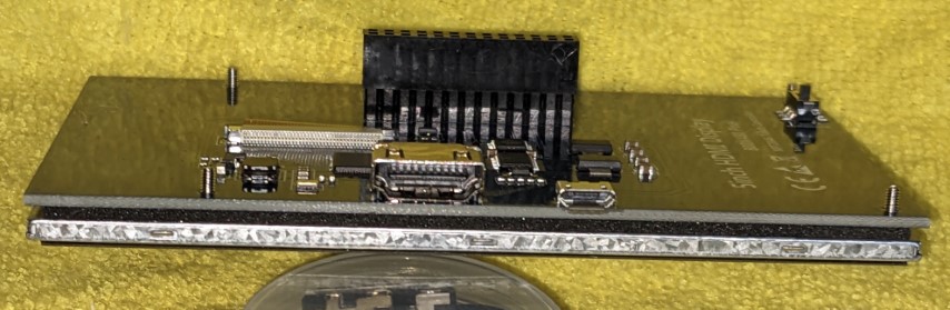
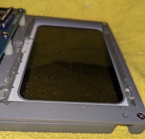
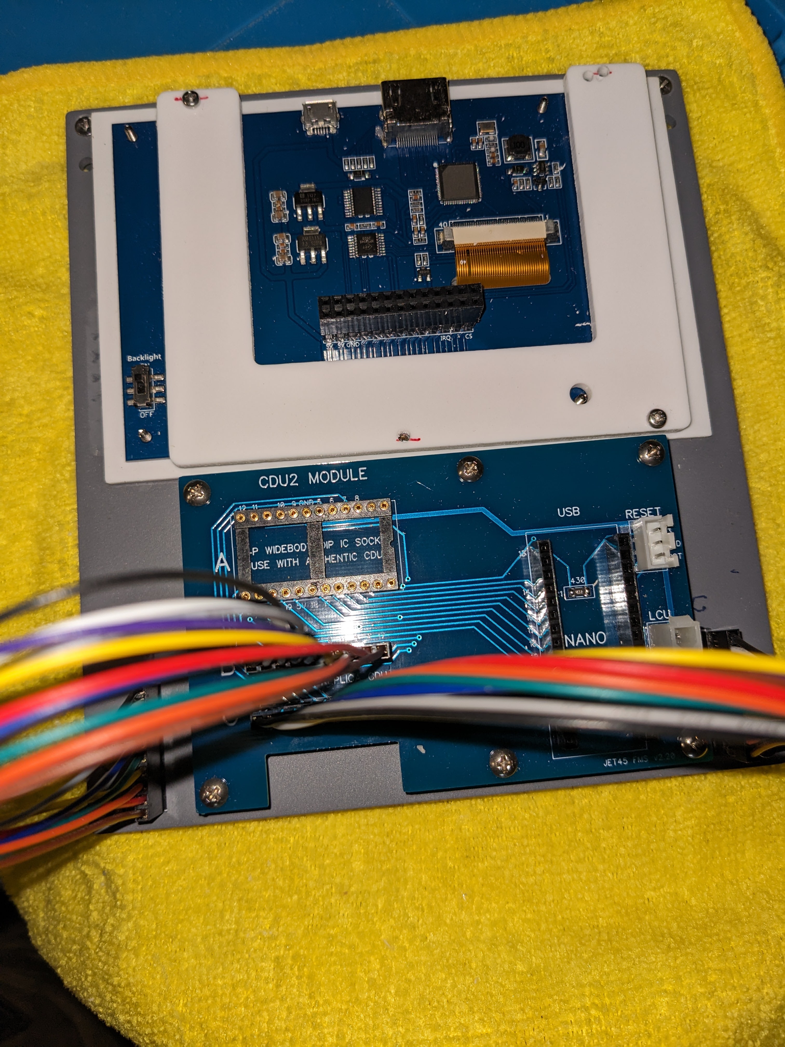
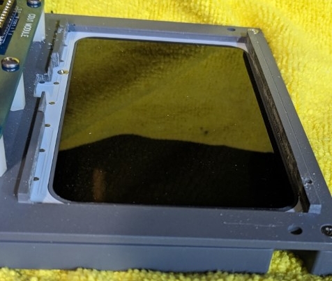
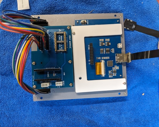
Hi Folks, another "If only I'd known" moment: When you order Rons CDU (if you haven’t, you should!) do be mindful of the 5” screens you get for them. It appears there are those where the screen and its PCB board are separate, joined only by the flat ribbon cable between screen and PCB, and those where the two pieces are attached permanently, stuck together back to back with a thin foam filler. For ease of installation, I recommend the 2 separate piece version. I got the “attached” version, which made the installation process slightly more involved! With the ‘separate’ PCB the screen sits nicely in the front pocket of the CDU backer piece with a good friction fit, you attach Rons PCB mount plate and mounting the PCB is easy. Job done. With the ‘attached’ variety the screen fits the cutout perfectly but the PCB behind it does not, it’s a couple of mm larger all around. Not only that but the recess is cut to take just the screen, not the PCB so even if you remove the very slight oversize of the PCB it will not sit flush with the face of the backer due to the flanges which hold the screen at the correct depth My first atempt to adapt the CDU was by milling off the raised screen mounting rails from the backer, with my cnc in manual mode – using the jog buttons. I then found that I had to create a 2.8mm thick packing piece to make the front of the screen flush with the front of the backer. I then made a “U” shaped piece from 3mm material to hold it all in place from the back with two M2.5 x 10mm screws in diagonal corners. . For the second one, I had another 'moment' when realized that the mounting rails are about 2.8mm high, so on this one I just milled off the depth stop flanges leaving the bulk of the mounting rail in place. The recess at the bottom(left side of photos) are for cable relief for the interconnect between screen and PCB. The screen slipped nicely into place. The oversize of the PCB set the correct depth resting on the mounting rail. Hold it in place with a “U” and two ,more M2.5 screws. Both ideas did the required job. It just would've been easier if got screens with separate PCB's! Hi Folks, another "If only I'd known" moment: When you order Rons CDU (if you haven’t, you should!) do be mindful of the 5” screens you get for them. It appears there are those where the screen and its PCB board are separate, joined only by the flat ribbon cable between screen and PCB, and those where the two pieces are attached permanently, stuck together back to back with a thin foam filler. For ease of installation, I recommend the 2 separate piece version. I got the “attached” version, which made the installation process slightly more involved! With the ‘separate’ PCB the screen sits nicely in the front pocket of the CDU backer piece with a good friction fit, you attach Rons PCB mount plate and mounting the PCB is easy. Job done. With the ‘attached’ variety the screen fits the cutout perfectly but the PCB behind it does not, it’s a couple of mm larger all around. Not only that but the recess is cut to take just the screen, not the PCB so even if you remove the very slight oversize of the PCB it will not sit flush with the face of the backer due to the flanges which hold the screen at the correct depth My first atempt to adapt the CDU was by milling off the raised screen mounting rails from the backer, with my cnc in manual mode – using the jog buttons. I then found that I had to create a 2.8mm thick packing piece to make the front of the screen flush with the front of the backer. I then made a “U” shaped piece from 3mm material to hold it all in place from the back with two M2.5 x 10mm screws in diagonal corners. . For the second one, I had another 'moment' when realized that the mounting rails are about 2.8mm high, so on this one I just milled off the depth stop flanges leaving the bulk of the mounting rail in place. The recess at the bottom(left side of photos) are for cable relief for the interconnect between screen and PCB. The screen slipped nicely into place. The oversize of the PCB set the correct depth resting on the mounting rail. Hold it in place with a “U” and two ,more M2.5 screws. Both ideas did the required job. It just would've been easier if got screens with separate PCB's! Hey guys, Here is a fun update to the CDUs. Talking to DonnyRay a couple weeks ago about the CDUs, he gave me the idea to add cooling fans to the replica CDUs. The real CDUs have cooling fans mounted in the side of the boxes they are mounted within and they NEED them because things can get warm in there. In the case of the replica CDUs, nothing really gets warm. The LCD screen stays cool, the back lighting is LED rather than incandescent bulbs and the only other thing that makes up the replica CDU is the Arduino Nano. That certainly doesn't get warm. Therefor, the only real reason to add cooling fans to the CDUs is to add avionics noise. The fans I have selected are brushless 12v fans. They are only $2 a piece. The hardware holding the fans in place is more expensive! The db level of these fans come in at 27db, just loud enough to hear them kicking online but once everything else is running, they will blend in with the soundscape. The other reason to add these fans to the replica CDUs is they finish off the back side perfectly. Before I went all in on this idea, one thing I had to check for was EMI because the fans are mounted so close to the Arduino Nano and the wires coming from the CDU Module to the CDU Panel. All test were PASS. This is made possible because the fans use brushless motors. As far as wiring them up, again, they are 12v and will be wired into the same 12v to 5v CDU converters, except they will be wired into the 12v terminals. (The LCD screens we are using require 5v power and the 12v to 5v converters are required.) All in all, it's a fun and easy modification to the CDUs. If you have a set of my Project45 replica CDUs and would like this fan update, just send me a message. It's these little details that make the difference in the simulation! CDU fan update kit below. Hey guys, Here is a fun update to the CDUs. Talking to DonnyRay a couple weeks ago about the CDUs, he gave me the idea to add cooling fans to the replica CDUs. The real CDUs have cooling fans mounted in the side of the boxes they are mounted within and they NEED them because things can get warm in there. In the case of the replica CDUs, nothing really gets warm. The LCD screen stays cool, the back lighting is LED rather than incandescent bulbs and the only other thing that makes up the replica CDU is the Arduino Nano. That certainly doesn't get warm. Therefor, the only real reason to add cooling fans to the CDUs is to add avionics noise. The fans I have selected are brushless 12v fans. They are only $2 a piece. The hardware holding the fans in place is more expensive! The db level of these fans come in at 27db, just loud enough to hear them kicking online but once everything else is running, they will blend in with the soundscape. The other reason to add these fans to the replica CDUs is they finish off the back side perfectly. Before I went all in on this idea, one thing I had to check for was EMI because the fans are mounted so close to the Arduino Nano and the wires coming from the CDU Module to the CDU Panel. All test were PASS. This is made possible because the fans use brushless motors. As far as wiring them up, again, they are 12v and will be wired into the same 12v to 5v CDU converters, except they will be wired into the 12v terminals. (The LCD screens we are using require 5v power and the 12v to 5v converters are required.) All in all, it's a fun and easy modification to the CDUs. If you have a set of my Project45 replica CDUs and would like this fan update, just send me a message. It's these little details that make the difference in the simulation! CDU fan update kit below. Hey guys, Just recently I finished up the physical CDU development and I think we can finally say it's complete......I think! You never know what the next best idea one of us will come up with, but for now, I think we can say the physical aspects of the CDU are complete. Now that I have the Jet45 FMS software loaded up on it, the next hurdle is to learn how to use it. I am not a real world pilot so my practical knowledge of how to operate the UNS1 is very limited. As a matter of fact, I was finding new ways to crash the software by asking it to do things it can't do or trying to do things out of sequence. I mentioned this to DonnyRay and he suggested that I try to find a UNS1 FMS Taskbook CAE, the standard version. Most of the ones out there are aircraft specific, as an example, Citation, Gulfstream, Lear35, etc... We want the standard version like this: As you can see, I found one on eBay for $35 plus shipping. I have only had a limited amount of time to run through it so far but already, I have reduced the amount of software crashes to nearly zero by following the procedures in this taskbook! Thanks for the tip DonnyRay! I also recommend finding one and using it. If you can't find a hard copy, no worries, you can find an older May 2002 PDF version of it HERE The other thing that I decided to do was build up a desktop CDU stand so that I can start learning the finer points of the Jet45 FMS software from the comforts of my desk while at the same time still build the sim. Not a whole lot to it. It's functional and it will do the job! Currently, I only have the 5" LCD screen and the Arduino Nano hooked to my research desktop computer. The back lighting is powered via a 9v battery only to "show it off" occasionally. The recently added cooling fan is not hooked up. I didn't want to ask anything more of this computer when it comes to USB power, I already have two faulty USB sockets on this computer. Hats off to Jason for his incredible work on the FMS software! I don't know how he does it but so thankful that he has developed the skills and has taken this project on with passion. And what's so cool, in order to learn how to use it, the best and recommended way is to use real world documentation like I pointed to above. Now that I have a desktop CDU testing station set up and proper training material, I am perfectly equipped to dig deeper into the FMS software and without crashing it! Another photo selecting KTPA as my departure airport! I run through this task book forwards and backwards a few times. Keep in mind this testing is off line and not hooked to a simulator yet. Hey guys, Just recently I finished up the physical CDU development and I think we can finally say it's complete......I think! You never know what the next best idea one of us will come up with, but for now, I think we can say the physical aspects of the CDU are complete. Now that I have the Jet45 FMS software loaded up on it, the next hurdle is to learn how to use it. I am not a real world pilot so my practical knowledge of how to operate the UNS1 is very limited. As a matter of fact, I was finding new ways to crash the software by asking it to do things it can't do or trying to do things out of sequence. I mentioned this to DonnyRay and he suggested that I try to find a UNS1 FMS Taskbook CAE, the standard version. Most of the ones out there are aircraft specific, as an example, Citation, Gulfstream, Lear35, etc... We want the standard version like this: As you can see, I found one on eBay for $35 plus shipping. I have only had a limited amount of time to run through it so far but already, I have reduced the amount of software crashes to nearly zero by following the procedures in this taskbook! Thanks for the tip DonnyRay! I also recommend finding one and using it. If you can't find a hard copy, no worries, you can find an older May 2002 PDF version of it HERE The other thing that I decided to do was build up a desktop CDU stand so that I can start learning the finer points of the Jet45 FMS software from the comforts of my desk while at the same time still build the sim. Not a whole lot to it. It's functional and it will do the job! Currently, I only have the 5" LCD screen and the Arduino Nano hooked to my research desktop computer. The back lighting is powered via a 9v battery only to "show it off" occasionally. The recently added cooling fan is not hooked up. I didn't want to ask anything more of this computer when it comes to USB power, I already have two faulty USB sockets on this computer. Hats off to Jason for his incredible work on the FMS software! I don't know how he does it but so thankful that he has developed the skills and has taken this project on with passion. And what's so cool, in order to learn how to use it, the best and recommended way is to use real world documentation like I pointed to above. Now that I have a desktop CDU testing station set up and proper training material, I am perfectly equipped to dig deeper into the FMS software and without crashing it! Another photo selecting KTPA as my departure airport! I run through this task book forwards and backwards a few times. Keep in mind this testing is off line and not hooked to a simulator yet. This past week I just finished up with the painting process on the Center Pedestal which means I now have a place to properly mount the CDUs. It has been a long time coming but I finally feel like everything is coming together. One of the last things I wanted to cover in this thread is how and where the CDUs get their power. The left CDU (FMS1) gets it's 12v power from the left ESS bus. The right CDU (FMS2) gets it's 12v power from the right ESS bus. Easy enough. The 5" LCD screens we have selected only require 5v power while the cooling fans need 12v power. Therefore a couple 12v to 5v converters are needed. If you are able to find LCD screens that require 12v power, you will be able to avoid using the converters in this area. But as it is, there are several places in the build that only require 5v power so these converters come in really handy. Here is a neat photo of the underside of the CDUs with both converters installed in the Center Pedestal. There is not a lot to the physical pieces of the CDUs compared to the real thing. At this point, the physical build of the CDUs are complete. We are now ready to properly test the Jet45 FMS software. If you have any questions or need additional information, please ask! This past week I just finished up with the painting process on the Center Pedestal which means I now have a place to properly mount the CDUs. It has been a long time coming but I finally feel like everything is coming together. One of the last things I wanted to cover in this thread is how and where the CDUs get their power. The left CDU (FMS1) gets it's 12v power from the left ESS bus. The right CDU (FMS2) gets it's 12v power from the right ESS bus. Easy enough. The 5" LCD screens we have selected only require 5v power while the cooling fans need 12v power. Therefore a couple 12v to 5v converters are needed. If you are able to find LCD screens that require 12v power, you will be able to avoid using the converters in this area. But as it is, there are several places in the build that only require 5v power so these converters come in really handy. Here is a neat photo of the underside of the CDUs with both converters installed in the Center Pedestal. There is not a lot to the physical pieces of the CDUs compared to the real thing. At this point, the physical build of the CDUs are complete. We are now ready to properly test the Jet45 FMS software. If you have any questions or need additional information, please ask! UNS1 Replica Development
![]()
![]()


![]()


![]()


2017-10-10