


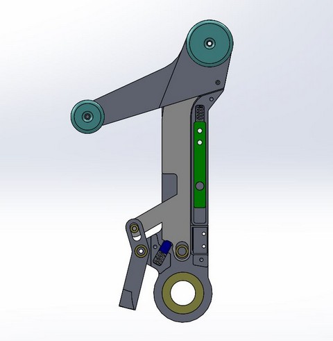
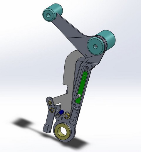
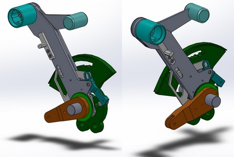
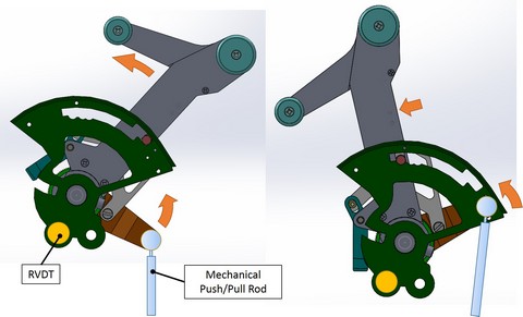
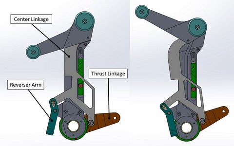
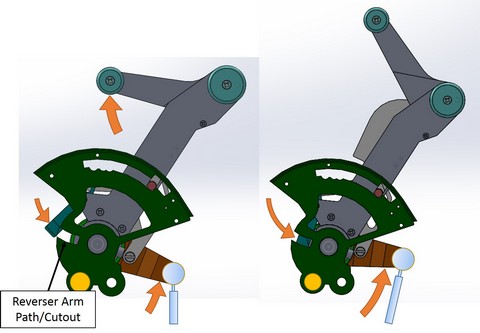
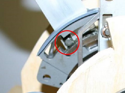
(Original thread started on 09-06-13 by Blake Olson) Have any of you lucky builders with a REAL LJ45 throttle taken it apart? The mechanics have been impressively hard for me to reverse engineer even with the manufacturer's assembly-level drawing. Any pictures would be appreciated! Here's the design I've been working on for a while now: Here’s a brief explanation and some CAD pictures showing how the Learjet45 throttle mechanically functions. I thought it might be helpful for some folks as I know it wasn't obvious to me at first: The travel limits of the throttle are set by a roller which follows a center slot/track. The throttle can be pushed forward from the idle position approx. 60 degrees. To get into the cutoff position the roller must be lifted by a pull lever on the outside of each throttle handle. It must also be lifted to enter the maximum thrust level: Automatic Performance Reserve (APR) As the throttle is moved forward from the idle position the Thrust Linkage (orange/brown color) rotates along with the movement of the throttle lever. The Thrust Linkage is attached to a gear (light green color**hard to see**) which turns another gear mounted to an RVDT (think: potentiometer). A mechanical push/pull rod is also attached to the end Thrust Linkage clevis which controls the engine fuel/thrust level mechanically: The throttle mechanism consists of (3) main linkages which I have labeled as the Center Linkage, Reverser Arm, and Thrust Linkage. As the throttle is moved forward from the idle position the Center Linkage stays seated within the throttle lever. When the reverser handle is lifted it moves up/forward moving the Reverser Arm and Thrust Linkage along with it: When in the idle position there is a path/cutout which the Reverser Arm can move into allowing the thrust reverse handle to be lifted. The reverser handle cannot be pulled back in any state other than idle due to the Reverser Arm being mechanically blocked from moving. There is also a solenoid which activates a gate mechanism (not shown) sitting above the Center Linkage which can keep the reverser handle from being moved if “weight-on-wheels” is not sensed: When the reverser handle is lifted, a variable amount of reverse thrust can be applied in the same way forward thrust would be applied only the main throttle lever is stationary (I thought this was a very clever mechanical design by the engineers at Adams Rite). At the same time, the aircraft deploys baffles on the engines to reverse the thrust direction when the reverser handle is lifted. Feel free to add or correct any details I may have missed. -Blake (Posted by Ron Rollo on 09-07-13) Very nice CAD work you have there. I can respect what your trying to do because I have been there! I was lucky to get my hands on the real parts which took care of all the difficult mechanical movements. I will tell you a few very neat features that the real levers do that you may be aware of but I'll mention them anyway for the sake of those who may not know. 1. When the throttles are all the way pulled back into CUT OFF position, the reverser levers are locked out, meaning you can not pull them back to activate them. This is to keep you from activating the reversers while the engines are not running. 2. When you push the levers from CUT OFF to Idle, they click into that position because of the little locking lever that you have drawn on the side. 3. When your in idle, you can not pull the throttles back into CUT OFF without pulling up on that little lever on the side. This is to protect the engines from accidentally being cut off. 4. On the other end of the throttle spectrum, you have to again lift up on the side lever to push the throttles up into APR (Auxiliary Performance Reserve), another safety feature. 5. Last but not least, there is a place for an electric solenoid that is designed to lock out the ability to activate the reversers in flight, or at least when there is no weight on wheels. We talk about this in the middle of post #3 HERE in this thread. I have not had time to find the right solenoids but it should be fairly easy to do. I did a little CAD drawing of how the mechanism will theoretically work. I have built several sets using real throttle parts for the builders and found a way to make most everything work. I obviously do not use real linkages, everything is working using potentiometers and switches. You said: "There is also a solenoid which activates a gate mechanism (not shown) sitting above the Center Linkage which can keep the reverser handle from being moved if “weight-on-wheels” is not sensed." If you or anyone knows of the correct solenoid that we need for the real throttle set, please let us know. This is the only feature that we are missing, the ones with real Lear45 throttles anyway. Great job Blake! (Posted by Mark L. on 09-07-13) Great drawings, would have helped to have had those a couple years ago. I can add though that even with these drawings, it's no small task to build a TQ and integrate the spoiler and flaps as well and match the real thing. I simplified the main levers as the complexity of the real one is not needed but has all the functionality, including the block for the Reverse Thruster without the use of a solenoid, but still requires a lot of time and steps to complete. I would like to see someone come up with a way to make the backlit cover like the original without expensive machinery or 5 axis CNC to do it. While I can create them, the heating and bending is the hard part to get a uniform factory smooth bend. I get close, but it's not perfect. The issue is the fact that I have to paint and engrave it first then bend it as I have no way to engrave after the fact. Second, the milling out of the backside of the cover to allow for the flexible circuit board with LED's to fit makes it hard to make a smooth bend due to the uneven thickness throughout the cover. That outside edge has to compress on the inside curve and there lies the problem. Like taking a I beam and bending it, doesn't work well. (Posted by Randy Buchanan on 09-09-13) Hey Mark, I agree. It is going to be a panel builder to come up with the curved one you build. The drawing shown here are just fantastic. And if you can draw them you can build them. I am sure we will all look forward to your first set Blake. Are you going to work in aluminum? We will have to see. But we can all enjoy the drawing now. (Posted by Blake Olson 09-09-13) I'm still in the planning stages for my CNC mill so an aluminum prototype is a ways off - but at least it gives me a reason to build the machine! As far as coming up with a way to make the backlit cover like the original without expensive machinery or 5 axis CNC to do it? Yeah, it will definitely be a challenge. I've used laser engravers with rotary wheels but then we're back in the "expensive machinery" department. If I think of something I'll definitely post it. Thanks for the comments guys. Full Disclosure: I'm 28 and a mechanical engineer - probably a lethal combination for getting into projects that are a bit ambitious - but I love this stuff! I plan on building a bigger CNC (I recently sold my small one) that can machine aluminum in order to get this made. The project is a ways down the road but I'll keep everyone updated as I go. I do have a few fairly specific questions about the real throttle: 1) Is there a friction adjustment for the levers? (I assume they don't just flop back and forth) 2) Does the circular piece that moves along the detent rail roll or just slide without rolling? See picture: (Posted by Ron Rollo on 12-11-16) Hey Olson, I'm glad to hear that your thinking of building a project down the road. Question one: In my TQ mod that I built, (refer to the thread I pointed to) I have four rods that can be tightened or loosen in order to get the right amount of resistance. Those rods are not part of the Lear45 throttle design. I would imagine that somewhere in their design they they address that, but it is not in the throttle handles. Question Two: Believe it or not, I can't recall if that pin is just a pin or if it rolls. (Eric is 99% sure it is a rolling pin) I would think that it would roll so that it does not turn flat on the bottom side with time and use. They use a fair amount of grease in that channel by the way to keep thing moving. With all that said, your not designing something that has to be air worthy so if it turns out that you use a pin rather than a rolling pin, I think you will be okay. (Original thread started on 09-06-13 by Blake Olson) Have any of you lucky builders with a REAL LJ45 throttle taken it apart? The mechanics have been impressively hard for me to reverse engineer even with the manufacturer's assembly-level drawing. Any pictures would be appreciated! Here's the design I've been working on for a while now: Here’s a brief explanation and some CAD pictures showing how the Learjet45 throttle mechanically functions. I thought it might be helpful for some folks as I know it wasn't obvious to me at first: The travel limits of the throttle are set by a roller which follows a center slot/track. The throttle can be pushed forward from the idle position approx. 60 degrees. To get into the cutoff position the roller must be lifted by a pull lever on the outside of each throttle handle. It must also be lifted to enter the maximum thrust level: Automatic Performance Reserve (APR) As the throttle is moved forward from the idle position the Thrust Linkage (orange/brown color) rotates along with the movement of the throttle lever. The Thrust Linkage is attached to a gear (light green color**hard to see**) which turns another gear mounted to an RVDT (think: potentiometer). A mechanical push/pull rod is also attached to the end Thrust Linkage clevis which controls the engine fuel/thrust level mechanically: The throttle mechanism consists of (3) main linkages which I have labeled as the Center Linkage, Reverser Arm, and Thrust Linkage. As the throttle is moved forward from the idle position the Center Linkage stays seated within the throttle lever. When the reverser handle is lifted it moves up/forward moving the Reverser Arm and Thrust Linkage along with it: When in the idle position there is a path/cutout which the Reverser Arm can move into allowing the thrust reverse handle to be lifted. The reverser handle cannot be pulled back in any state other than idle due to the Reverser Arm being mechanically blocked from moving. There is also a solenoid which activates a gate mechanism (not shown) sitting above the Center Linkage which can keep the reverser handle from being moved if “weight-on-wheels” is not sensed: When the reverser handle is lifted, a variable amount of reverse thrust can be applied in the same way forward thrust would be applied only the main throttle lever is stationary (I thought this was a very clever mechanical design by the engineers at Adams Rite). At the same time, the aircraft deploys baffles on the engines to reverse the thrust direction when the reverser handle is lifted. Feel free to add or correct any details I may have missed. -Blake (Posted by Ron Rollo on 09-07-13) Very nice CAD work you have there. I can respect what your trying to do because I have been there! I was lucky to get my hands on the real parts which took care of all the difficult mechanical movements. I will tell you a few very neat features that the real levers do that you may be aware of but I'll mention them anyway for the sake of those who may not know. 1. When the throttles are all the way pulled back into CUT OFF position, the reverser levers are locked out, meaning you can not pull them back to activate them. This is to keep you from activating the reversers while the engines are not running. 2. When you push the levers from CUT OFF to Idle, they click into that position because of the little locking lever that you have drawn on the side. 3. When your in idle, you can not pull the throttles back into CUT OFF without pulling up on that little lever on the side. This is to protect the engines from accidentally being cut off. 4. On the other end of the throttle spectrum, you have to again lift up on the side lever to push the throttles up into APR (Auxiliary Performance Reserve), another safety feature. 5. Last but not least, there is a place for an electric solenoid that is designed to lock out the ability to activate the reversers in flight, or at least when there is no weight on wheels. We talk about this in the middle of post #3 HERE in this thread. I have not had time to find the right solenoids but it should be fairly easy to do. I did a little CAD drawing of how the mechanism will theoretically work. I have built several sets using real throttle parts for the builders and found a way to make most everything work. I obviously do not use real linkages, everything is working using potentiometers and switches. You said: "There is also a solenoid which activates a gate mechanism (not shown) sitting above the Center Linkage which can keep the reverser handle from being moved if “weight-on-wheels” is not sensed." If you or anyone knows of the correct solenoid that we need for the real throttle set, please let us know. This is the only feature that we are missing, the ones with real Lear45 throttles anyway. Great job Blake! (Posted by Mark L. on 09-07-13) Great drawings, would have helped to have had those a couple years ago. I can add though that even with these drawings, it's no small task to build a TQ and integrate the spoiler and flaps as well and match the real thing. I simplified the main levers as the complexity of the real one is not needed but has all the functionality, including the block for the Reverse Thruster without the use of a solenoid, but still requires a lot of time and steps to complete. I would like to see someone come up with a way to make the backlit cover like the original without expensive machinery or 5 axis CNC to do it. While I can create them, the heating and bending is the hard part to get a uniform factory smooth bend. I get close, but it's not perfect. The issue is the fact that I have to paint and engrave it first then bend it as I have no way to engrave after the fact. Second, the milling out of the backside of the cover to allow for the flexible circuit board with LED's to fit makes it hard to make a smooth bend due to the uneven thickness throughout the cover. That outside edge has to compress on the inside curve and there lies the problem. Like taking a I beam and bending it, doesn't work well. (Posted by Randy Buchanan on 09-09-13) Hey Mark, I agree. It is going to be a panel builder to come up with the curved one you build. The drawing shown here are just fantastic. And if you can draw them you can build them. I am sure we will all look forward to your first set Blake. Are you going to work in aluminum? We will have to see. But we can all enjoy the drawing now. (Posted by Blake Olson 09-09-13) I'm still in the planning stages for my CNC mill so an aluminum prototype is a ways off - but at least it gives me a reason to build the machine! As far as coming up with a way to make the backlit cover like the original without expensive machinery or 5 axis CNC to do it? Yeah, it will definitely be a challenge. I've used laser engravers with rotary wheels but then we're back in the "expensive machinery" department. If I think of something I'll definitely post it. Thanks for the comments guys. Full Disclosure: I'm 28 and a mechanical engineer - probably a lethal combination for getting into projects that are a bit ambitious - but I love this stuff! I plan on building a bigger CNC (I recently sold my small one) that can machine aluminum in order to get this made. The project is a ways down the road but I'll keep everyone updated as I go. I do have a few fairly specific questions about the real throttle: 1) Is there a friction adjustment for the levers? (I assume they don't just flop back and forth) 2) Does the circular piece that moves along the detent rail roll or just slide without rolling? See picture: (Posted by Ron Rollo on 12-11-16) Hey Olson, I'm glad to hear that your thinking of building a project down the road. Question one: In my TQ mod that I built, (refer to the thread I pointed to) I have four rods that can be tightened or loosen in order to get the right amount of resistance. Those rods are not part of the Lear45 throttle design. I would imagine that somewhere in their design they they address that, but it is not in the throttle handles. Question Two: Believe it or not, I can't recall if that pin is just a pin or if it rolls. (Eric is 99% sure it is a rolling pin) I would think that it would roll so that it does not turn flat on the bottom side with time and use. They use a fair amount of grease in that channel by the way to keep thing moving. With all that said, your not designing something that has to be air worthy so if it turns out that you use a pin rather than a rolling pin, I think you will be okay.Learjet45 Throttle Mechanical Details
![]()
2017-10-10