


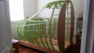
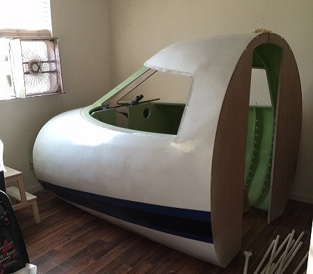
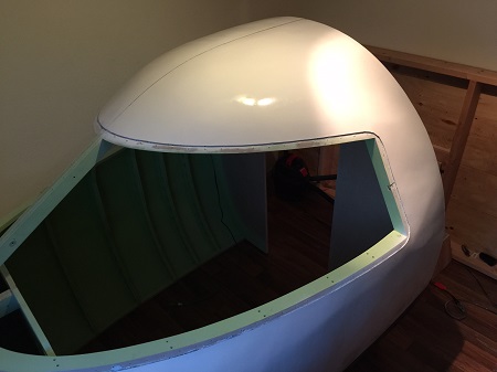
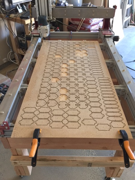
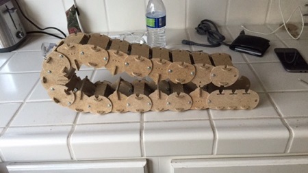
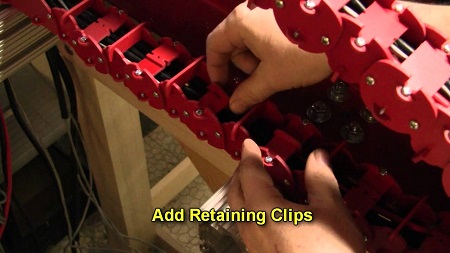
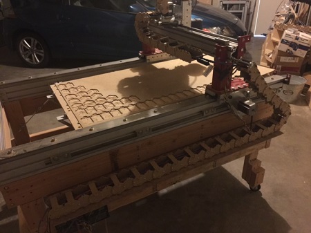
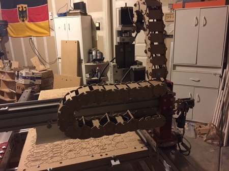
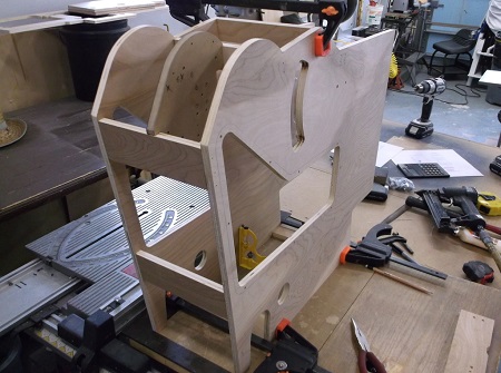
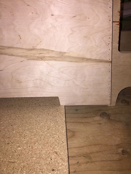
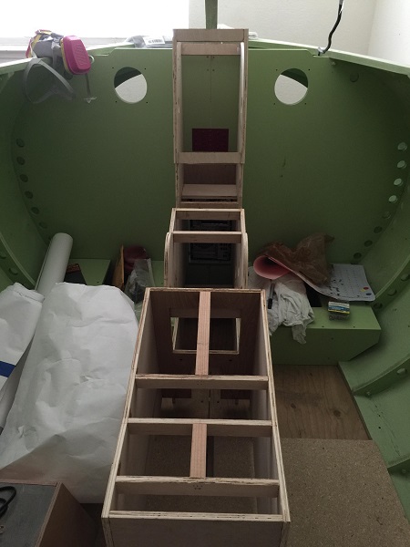
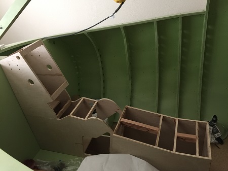
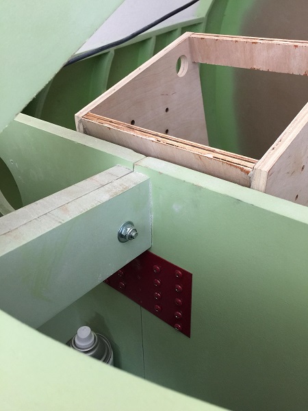
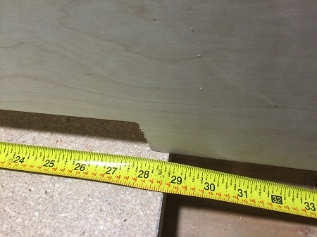
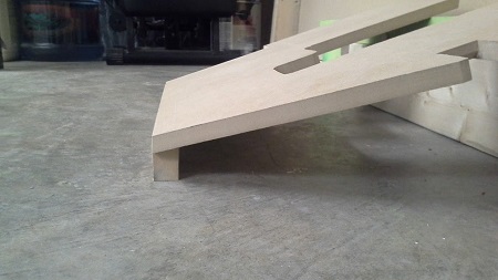
(Original thread started on 10-09-14 by Steve Cooke) So I figured it's time to start my thread. I've been progressing along pretty well on building the shell but a few issues over September put me behind in finishing up. I'll have to post pictures which are sitting on my phone but truthfully I've been a bit lazy to select and email them to myself! Anyways I'm finishing up with the silicone caulking on the alloy and should have the inside of the shell completely painted this weekend before moving on to the spray foam. Since I'm looking ahead to the fiberglass phase and of what I remember as it has been awhile since I've glassed anything, I had a couple of questions to those who have made it past this part. What resin did you use? Poly or Epoxy? If you went with Poly did you use with wax or without wax or a combination of both (no wax on first layer and with wax on second layer). The SAM mentions that about 6 gals was used. Seems like a lot. From what I remember when working with my dad on glassing a wood boat, we didn't come close to that. Again it's been a while so I can't say for sure how much we used on that project. I wanted to get the stuff ordered now before the wife decides she wants to spend the money to demo another room in our house and remodel! Not another project I would be looking forward to. You can see my photos of the shell HERE (Posted by Shane Barnes on 10-09-14) Hi Steve, I purchased my fiberglass resin at Wal-Mart. Worked fine. I think I applied 3 to 4 layers of fiberglass mat. No wax needed. Here is a link to what I used: http://www.walmart.com/ip/Bondo-Fiberglass-Resin/17130349 You can check around to see if you can find it cheaper but at the time I did my shell (several years ago) Wal-Mart was the cheapest. I ordered my fiberglass mat from Jamestown distributors. Buy it in bulk and it is cheaper. I cannot recall how much I used on the shell but it takes quite a bit. The surface area is larger than what it appears. (Posted by Ron Rollo on 10-09-14) The shell was my first big fiberglass project. If you have a little bit of experience with fiberglass boats, the shell will be a piece of cake for you. The SAM mentions that I used about six gallons. The question is how many gallons actually made it into the shell? Some was wasted, cut away and then sanded away. I would guess that there are about four gallons of fiberglass total in the project, the other two were wasted or excess. I got my fiberglass from Advanced Discount Auto Parts. Any auto parts store will have gallons of glass. Just shop around a little, Wal Mart is a good place to check as Shane pointed out. (Posted by Steve Cooke on 10-14-14) The caulking is just about done. I should be done tonight. I'm going to re do the very front panels on the overhead. I didn't like how they came out and I still have some alloy left over. I looked at Jamestown for the fiberglass and I think it was like $5 or so for a roll at 3yrds x 38". Maybe a bit more but really reasonable. I'm really looking forward to the shell being finished so I can move on into the inside. My wife and a few family members think I'm making a spaceship, and one is have a hard time wrapping their head around how it will all work with FS. I'll grab a few more pics and get something posted tomorrow. I've finished with the silicon today minus the panel 6 on the top. If I had to do the siding all over again, I would have done a few things different but overall the mistakes will be hidden with the stray foam and paneling on the inside. I hope to be painting the inside this weekend and starting with the spray foam. I still need to finish cleaning up my office. I have one more desk to get rid of, install some shelves and then move our guinea pig to the family room. You will find a link to my photos HERE I'm actually going to build a clean room around the Lear (or to some may look like a Bio Hazard tent). I've been putting that off until the rest of the office gets cleaned up. I could run them downstairs but it's the 90 deg turn half way down that may take me for a ride. I can feed the halves over the railing down to the living room but that would require a few people around to help. I wanted a 3 car garage so I could house my shell there but that didn't happen when we were house hunting. So my plan will be to some PVC piping and build a frame around the shell and then seal it off with clear plastic painters drop cloth (the thicker kind over thin), then set up ventilation to vent everything out the window. It's something I've done before with my dad and grandpa when they were restoring cars, so I know that would work. So the mess will be contained and cleanup will be easy. I did something similar during the sanding and shaping prior to painting, just not elaborate. You couldn't tell that I was using a belt and orbital sander in my office. The clean room setup is much easier for me. My wife and daughter help from time to time but asking them to help me handling this thing down the stairs gets me some funny looks. I finished with all the silicone last night so I'm letting everything cure. This weekend I'll finish up the few shelves I need to install to get the last desk out of the office. Then I'll start building. I hope to have that done by Sunday if everything goes as planned. (Posted by Steve Cooke on 10-25-14) I haven't finished my clean room yet but I've uploaded a few pictures. Life tends to throw me a curve ball when I'm on a roll working on the flight deck. I built it out of PVC pipes that I have for a yard project but since it's already cold out and raining I'm using them for this in the mean time. It's covered with plastic painters drop cloth. I've cut a square around the window where my box fan is to vent any fumes out. By my desk I'll setup a box fan to feed clean air in. That box fan will have one of those cheap $2 air filters for AC's attached to the front blowing in to keep crap from filtering in. I didn't put a vertical pole by my desk as I'm using that area to come in and out of, plus it's easy to drop the 2 bottom PVC pipes so I can sit in my chair and play Star Trek Online while I wait for the foam, etc to cure. I did a similar setup when I shaved the ribbing down prior to painting the shell and it kept all the dust contained. I still need to finish wrapping the wall on the back side and top. Plus I'll drop plastic down on the floor so the whole area will be closed off from the room. I know there will be main way's of doing this but I was going to a shoestring budget since it's not permanent. If you want more pictures of have questions let me know. I'll post up another shot when it's all done. I'm hoping tomorrow. You will find a link to my photos HERE UPDATE: I have pretty much finished all the sanding on the foam yesterday. I noticed ta the port side expanded a hair bit more in a few spots after sitting a few days so I need to do some touch up there. I'm going to be starting on the windscreen template today but did not see in the manual what screws are used to secure the template/Plexi to the frame. So I wanted to find out since I'll be at one of the box stores this afternoon picking up the door skin. I have more pictures but started a new album with a different site. (Posted by Ron Rollo on 11-17-14) Hey Steve, I used a Philips head (I think they call it a truss head). They are 5/8" long and are a wood screw. I want to say they are galvanized steal, in other words cheap because they will end up getting discarded after the fiberglass and painting. Later on you will use stainless steel Phillip pan-head screws to hold the Lexan windscreens in place. I hope this info helps. If you need me to I will send you a few sample screws of what I used. (Posted by Steve Cooke on 11-25-14) So this evening I finished installing the windscreen template. I'm hoping to have the fiberglass done this weekend. You will find a link to the new pics in my new album HERE I'm also glad the clean room held up really well. The only dust that came out was from my shoes and what was on my face. I picked up one of those full body paint suites with a cap. Wearing my mask and goggles, hardly any skin was exposed. Really cool. You'll see the clean room in the pictures. (Posted by Ron Rollo on 11-25-14) Hey Steve, the photos look really cool and familiar! As for the fiberglass being completed in one weekend? Don't rush it. Take your time and try to get it right. The other thing that I will warn you about is that your clean room is getting ready to be trashed with all the fiberglass dust your going to make with your orbital sander. The best place to do this type of work is outside under a carport or some sort of cover that is well ventilated. If you have to do it indoors, you might want to get a filter system to pull most of the fiberglass dust out of the air. The good news is that once it is done, your done! Great work Steve! (Posted by Steve Cooke on 11-26-14) Hey Ron, I'm not worried about the clean room. It was really to keep my office clean of all the dust and stuff. Since it's disposable, if I need to replace plastic as I go, it won't be an issue. I have a bunch of rolls left over from painting our house. I have a heavy fan coming in tonight for venting and help with laying the fiberglass this weekend. I figure if the family is coming to my house, put them to work. LOL. My main goal is to have the fiberglass laid over the 4 day weekend. My dad and I have laid glass before and he is still current with it which will greatly help in the process. I can take care of sanding and painting on my own during downtime at work. They have me stretched thin over the next few weeks with 6 days in SoCal and 4 days in Arizona. Traveling for work stinks because it takes away from my LearJet time! Since I'll have some time off for Christmas, my goal is to have the shell painted and done by New Years weekend. (Posted by Steve Cooke on 04-06-16) I had went from 2 layers of glass to 4. 3 layers of matting and topped it off with a layer of cloth. It came out pretty nice. I'll get some pictures uploaded today. The clean room I built around the shell worked great. The only dust that really came out of it was from the paint suit I was wearing, so dust was down to a minimum. I haven't put in the windscreen yet. I was going to hold off until I have the glare shield in place. Being as clumsy as I am at times, I don't want to scratch up the Plexi. I'm pretty pleased with the work. I could have spend another 6 months just sanding, Bondo and shaping the shell. I had to call it quits on that and move on or this project would never move forward. I know my wife is happy that the office is all cleaned up. Now I can move all my stuff back in! I did use the templates. It made shaping much easier and kept the inside from becoming a disaster area with resin: (Posted by Shane Barnes on 04-19-15) Nice job Steve! I'm not sure how many "fiberglass shells" that makes in our group. I know Ron and I did the fiberglass, anyone else? It is a lot of work but it makes a really nice shell once completed. Steve, hold off on installing the windscreen as long as you can. When you start wiring and adding stuff you will want access to the area behind the MIP, it makes it much easier if no windscreen is in place. I've not installed mine yet. I don't plan on installing until I have all wiring in place and everything working the way I want it. (Posted by Ron Rollo on 04-20-15) On the other hand, my windscreens have been in place for a few years now. I have also been flying during this time. It is possible to do work within the sim with the windscreens in place but you have to be careful. In your case, your no where near ready for them so defiantly hold off like Shane suggest until you can't stand it any longer! (Posted by Maciej on 04-22-15) Your "clean room" is a simple and brilliant idea due to fact that you don't move fragile shell from place to place and it suits not only sanding but painting as well! I know at some point of the project I need to embrace it and may go all the way and join the club. I will follow your design. What size of PVC pipe did you use ? It looks like 1", any preferences on plastic foil? (Posted by Steve Cooke on 04-24-15) Thanks all. I'm definitely going to hold out on the windscreen for as long as possible. I managed to finish my 2nd attempt on the TQ pedestal. It was coming out nice but once together it's off square by 2mm. I not only used finishing nails to hold the cross pieces in but I glued them down too. So on to version #3. Right now I just shifted my efforts to finish revamping my CNC machine and then I'll move back to the sim. I used 1/2" but I would recommend using 3/4 to 1" and to have a good tight fit. My fittings ended up getting lose over time so I just plugged small drywall screws through the joints to hold them together. As for plastic, it depends on the size of the clean room. Mine was the size of my office so it was a bit right to move around in. If I had to do the plastic over again during the heavy work, I would have gone with a thicker plastic. I ended up buying a 5 pack of plastic at Lowes Item #653493 and a few rolls of duct tape. My fan was a box fan in the windows. I put cardboard around the box fan and then taped the cardboard to the plastic. I also used a cheap $2 AC filter on the opposite side of the window for the intake, to keep the dust out of my office. I also dropped plastic down on the floor. It made clean up so much easier. A little bit of vacuuming and I was all set. The fumes from the fiberglass resin was minimal. Outside of my office you couldn't smell anything. In the office but outside the clean room was minimal, i didn't need to wear a mask. In the clean room, you definitely need a mask. It actually works out pretty well. It was something that popped into my head remembering when my dad and grandpa used to do body work and paint cars on the side. I just scaled it down. My dad had started calling me Dexter when I put up new plastic for paint. It was kinda funny. Only thing I was able to accomplish this weekend on the build was dropping in the raised floor. it fit pretty well. Otherwise I've been working on cutting all the new parts for my CNC machine for its overhaul. I haven't used AutoCAD in a while so part of my time was spent trying to remember all the shortcuts to drawing. I was lucky as my daughter had to learn AutoCAD in her industrial design class. I wish they had these classes when I was in high school. I may employ her skills, LOL. (Posted by Steve Cooke on 11-05-15) So I've been off of the Lear project for a few months. I had rebuilt my CNC machine. V3 ended up being a flop as I couldn't square it up for the life of me. My wife finally agreed that I could spend the money and buy a nice table. So like any happy kid, I did just that right before she finished her sentence so she couldn't change her mind. Here's my new table. 2'x4' cutting surface. All the electronics are from my previous DIY tables. These pics show the table track I'm making for the x, y and z axis. I hope to have this all mounted up and back to cutting parts this weekend: I have a little bit more tweaking to do and trying to make heads and tales of Mach3 as to why every time i turn on the PC and launch it my steps need to be re-calibrated. One day I can cut 5" and only be .001" off and the next day nothing has changed, I'm cutting 4.81". A quick 5 min to re-calibrate is okay, but time does add up after a while. I'm also looking at buying the high speed precision collet when it comes to panel engraving. Hope to back into full swing this Labor Day weekend. If you are wondering what I am cutting out, it's a cable track for my CNC. I got the idea from here: and then just worked it up in CAD. After a few test cuts and 2 test links, I've came up with this product. eventually I'll cut it in plastic, but for now it will keep the wires out of the way. UPDATE: I finished up my CNC machine. All the cable tracks I made have been installed, wires fed through and nothing is binding up. I finished squaring everything up and is only off by .0012". The calibration for travel is i think off by .0015" due to using a tape measure instead of caliper. Large calipers seem to be more expensive than what its worth. Here's what I have so far: Today, I'll start back on the pedestals. (Posted by Steve Cooke on 11-30-15) Well I managed to finish building the TQ pedestal this weekend. I thought the whole thing was squared up but when I looked at it this morning and rechecked it all again, I'm finding it is not. What type of jigs is everyone using to keep the pedestals square while the glue dries? Also has anyone used particle/MDF/HDF boards instead of birch? It's getting a bit expensive making firewood. I'll check one more time when I get home this afternoon to see if I'm squared up. Just a little frustrating. (Posted by Ron Rollo on 11-30-15) Hey Steve, sorry to here you are going through some headaches. This is one of those areas that require a lot of attention. The first thing you have to have is square parts which is not a problem. The next thing you need is a super flat and level work space. And then some levels and squares. I use the table saw cutting surface. It is flat and level. Then I use a large metal square, clamps and levels. Take a look at this photo: Notice the metal square running across the front and left side at the bottom? And notice the yellow level in the photo? A larger level would have been better but quadruple checking will work too! In the process of gluing pieces together, I use other pieces as spacers and clamp it all together. Once you have two or three crossovers glued and nail gunned into place, let it sit and insure it is square. Check and double check. I hope this info helps. By the way, I would only use Birch or Oak in this area. MDF is possible but the finish work will not be as clean as real wood. I built at least six of these things and I have learned a lot along the way. What I don't want to hear is that you have built six also with only one to show for! So if you have any other questions, please ask. (Posted by Steve Cooke on 11-30-15) I see what you have going on. My first 3 were failed cuts on my CNC v2. CNC v3 gave me parts that were not equal and a failed build on that. That's when I bought my new table. This one I built 2 and both came out skewed. This one I worked on over 3 days and from last night when I added the last 2 cross pieces it was still square and this morning everything shifted. I hope weather didn't have a play in it causing the wood to swell and flex. It dropped down pretty cold last night and the garage was like a fridge this morning. That was when I pulled the clamps and checked everything to see if it was square and found it was not. I'll take another stab but make some extra jigs and buy some more clamps tomorrow. I have two small ones like yours and two big ones that are a pain to work with on small pieces. My next question as I didn't see any pictures here. How are the panels being mounted to the pedestals? There is a route I was considering from the days when I was going to build a 737. I'm pretty sure I could adopt it into this build but before I go that route wanted to see what everyone else did? (Posted by Ron Rollo on 12-01-15) Most of us are drilling holes in the wood and using my DZUS replica kit. They look like DZUS fasteners but they are nothing more than screws that screw into the wood. One or two guys are attempting to use real DZUS rails and fasteners but I worry about if the panels will line up perfectly with the rails. They should, I have never tried. With wood you can drill the holes where ever you need them. (Posted by Steve Cooke on 12-01-15) That's what I had thought. I was considering using 3/4" x 3/4" 1/8" Alloy solid angle brackets. I've seen those used on 737 builds and then just drill holes and tap them. My only concern was and would be my luck is eventually the wood will wear from adding and removing panels from the work being done on them. I was planning on using your DZUS package. From the pictures, they look like machine screws. Are the machine or wood screws? My estimates may be off but from what I can tell, the DZUS screws are about 1/4"x1/4" in on each corner? It looks more possible like 3/8" in but I'm just eyeballing it. (Posted by Eric Tomlin on 12-02-15) They are machine screws. I would not worry about the wood wearing. Ron and the rest of us have installed and removed panels many, many times with no issue. However, a good solution for you might be to lay your backer panel down, mark the spot for the mounting/faux Dzus holes, drill, then install a "fitting screw". It's now threaded somewhat in the Birch, so then simply remove that screw and squirt a little super-thin CA glue down in the hole and that will harden the fibers up more. Thankfully though, Birch (as you know by now) is a nice tight-grained material and really doesn't need the CA trim in my opinion. As for spacing, it's really a best practice to not do any holes until you receive the backer panels from your panel supplier, which is typically myself and Ron if you do not make them yourself. I'd be glad to go ahead and get your backers made and sent out to you if that's something you'd like to do before buying the front panels (and again, you may have another source of panels- just offering to be helpful). Also, real Dzus spacing is .375" (3/8") from hole to hole and .129" from the edge of an SAE 7788 panel. (Posted by Alan Norris on 12-02-15) I used plywood for the console and when I had my panels in place and the holes marked for the dummy Dzus fasteners I used threaded inserts of the correct size for the machine screws. That way you can remove the panels any number of times and you will never have any issues. (Posted by Steve Cooke on 12-15-15) Made some progress on the pedestals. I finished the TQ and Center pedestals and will be starting on the MIP Riser this week. I'm also reviewing th MIP Backer Support. Is this milled out of 1 piece of wood or is this broken up into three pieces? I can see how this could be done either way. It also looks like from the pictures it was made out of MDF? One last question. From the what the plans on the raised floor shows to having the TQ and Center Pedestals in place, the raised floor seems to be a bit too long. The Center Pedestal does not drop down to the main floor. I wanted to confirm that its just a rough estimate or should I just mill out the section i need to get the pedestal to drop into place. (Posted by Ron Rollo on 12-16-15) The last few MIP backers that I have made for members has been out of .5" thick Birch. Then you would use .5" X .5" Birch strips to frame the LCD monitors. Do you have your monitors yet? There are several brands to choose from but the main thing that you MUST have is two 15" standard monitors and one 15" wide screen monitor. Lenovo, IBM and Dell have a selection of used 15" monitors and Acer has the 15" wide screen monitor. Once you have them you will be able to see exactly how big your backer is going to be. There should be plenty of photos as good examples of what your trying to achieve. One quick tip is that as you are building up you furniture, fine tune things from the ground up. Make sure your floor, TQ pedestal and Center pedestal fit perfectly before you move on to the MIP tower, MIP backer and MIP. Last but not least would be the glare shield. Take some photos of the floor section that you have questions about so that I can point you in the right direction. (Original thread started on 10-09-14 by Steve Cooke) So I figured it's time to start my thread. I've been progressing along pretty well on building the shell but a few issues over September put me behind in finishing up. I'll have to post pictures which are sitting on my phone but truthfully I've been a bit lazy to select and email them to myself! Anyways I'm finishing up with the silicone caulking on the alloy and should have the inside of the shell completely painted this weekend before moving on to the spray foam. Since I'm looking ahead to the fiberglass phase and of what I remember as it has been awhile since I've glassed anything, I had a couple of questions to those who have made it past this part. What resin did you use? Poly or Epoxy? If you went with Poly did you use with wax or without wax or a combination of both (no wax on first layer and with wax on second layer). The SAM mentions that about 6 gals was used. Seems like a lot. From what I remember when working with my dad on glassing a wood boat, we didn't come close to that. Again it's been a while so I can't say for sure how much we used on that project. I wanted to get the stuff ordered now before the wife decides she wants to spend the money to demo another room in our house and remodel! Not another project I would be looking forward to. You can see my photos of the shell HERE (Posted by Shane Barnes on 10-09-14) Hi Steve, I purchased my fiberglass resin at Wal-Mart. Worked fine. I think I applied 3 to 4 layers of fiberglass mat. No wax needed. Here is a link to what I used: http://www.walmart.com/ip/Bondo-Fiberglass-Resin/17130349 You can check around to see if you can find it cheaper but at the time I did my shell (several years ago) Wal-Mart was the cheapest. I ordered my fiberglass mat from Jamestown distributors. Buy it in bulk and it is cheaper. I cannot recall how much I used on the shell but it takes quite a bit. The surface area is larger than what it appears. (Posted by Ron Rollo on 10-09-14) The shell was my first big fiberglass project. If you have a little bit of experience with fiberglass boats, the shell will be a piece of cake for you. The SAM mentions that I used about six gallons. The question is how many gallons actually made it into the shell? Some was wasted, cut away and then sanded away. I would guess that there are about four gallons of fiberglass total in the project, the other two were wasted or excess. I got my fiberglass from Advanced Discount Auto Parts. Any auto parts store will have gallons of glass. Just shop around a little, Wal Mart is a good place to check as Shane pointed out. (Posted by Steve Cooke on 10-14-14) The caulking is just about done. I should be done tonight. I'm going to re do the very front panels on the overhead. I didn't like how they came out and I still have some alloy left over. I looked at Jamestown for the fiberglass and I think it was like $5 or so for a roll at 3yrds x 38". Maybe a bit more but really reasonable. I'm really looking forward to the shell being finished so I can move on into the inside. My wife and a few family members think I'm making a spaceship, and one is have a hard time wrapping their head around how it will all work with FS. I'll grab a few more pics and get something posted tomorrow. I've finished with the silicon today minus the panel 6 on the top. If I had to do the siding all over again, I would have done a few things different but overall the mistakes will be hidden with the stray foam and paneling on the inside. I hope to be painting the inside this weekend and starting with the spray foam. I still need to finish cleaning up my office. I have one more desk to get rid of, install some shelves and then move our guinea pig to the family room. You will find a link to my photos HERE I'm actually going to build a clean room around the Lear (or to some may look like a Bio Hazard tent). I've been putting that off until the rest of the office gets cleaned up. I could run them downstairs but it's the 90 deg turn half way down that may take me for a ride. I can feed the halves over the railing down to the living room but that would require a few people around to help. I wanted a 3 car garage so I could house my shell there but that didn't happen when we were house hunting. So my plan will be to some PVC piping and build a frame around the shell and then seal it off with clear plastic painters drop cloth (the thicker kind over thin), then set up ventilation to vent everything out the window. It's something I've done before with my dad and grandpa when they were restoring cars, so I know that would work. So the mess will be contained and cleanup will be easy. I did something similar during the sanding and shaping prior to painting, just not elaborate. You couldn't tell that I was using a belt and orbital sander in my office. The clean room setup is much easier for me. My wife and daughter help from time to time but asking them to help me handling this thing down the stairs gets me some funny looks. I finished with all the silicone last night so I'm letting everything cure. This weekend I'll finish up the few shelves I need to install to get the last desk out of the office. Then I'll start building. I hope to have that done by Sunday if everything goes as planned. (Posted by Steve Cooke on 10-25-14) I haven't finished my clean room yet but I've uploaded a few pictures. Life tends to throw me a curve ball when I'm on a roll working on the flight deck. I built it out of PVC pipes that I have for a yard project but since it's already cold out and raining I'm using them for this in the mean time. It's covered with plastic painters drop cloth. I've cut a square around the window where my box fan is to vent any fumes out. By my desk I'll setup a box fan to feed clean air in. That box fan will have one of those cheap $2 air filters for AC's attached to the front blowing in to keep crap from filtering in. I didn't put a vertical pole by my desk as I'm using that area to come in and out of, plus it's easy to drop the 2 bottom PVC pipes so I can sit in my chair and play Star Trek Online while I wait for the foam, etc to cure. I did a similar setup when I shaved the ribbing down prior to painting the shell and it kept all the dust contained. I still need to finish wrapping the wall on the back side and top. Plus I'll drop plastic down on the floor so the whole area will be closed off from the room. I know there will be main way's of doing this but I was going to a shoestring budget since it's not permanent. If you want more pictures of have questions let me know. I'll post up another shot when it's all done. I'm hoping tomorrow. You will find a link to my photos HERE UPDATE: I have pretty much finished all the sanding on the foam yesterday. I noticed ta the port side expanded a hair bit more in a few spots after sitting a few days so I need to do some touch up there. I'm going to be starting on the windscreen template today but did not see in the manual what screws are used to secure the template/Plexi to the frame. So I wanted to find out since I'll be at one of the box stores this afternoon picking up the door skin. I have more pictures but started a new album with a different site. (Posted by Ron Rollo on 11-17-14) Hey Steve, I used a Philips head (I think they call it a truss head). They are 5/8" long and are a wood screw. I want to say they are galvanized steal, in other words cheap because they will end up getting discarded after the fiberglass and painting. Later on you will use stainless steel Phillip pan-head screws to hold the Lexan windscreens in place. I hope this info helps. If you need me to I will send you a few sample screws of what I used. (Posted by Steve Cooke on 11-25-14) So this evening I finished installing the windscreen template. I'm hoping to have the fiberglass done this weekend. You will find a link to the new pics in my new album HERE I'm also glad the clean room held up really well. The only dust that came out was from my shoes and what was on my face. I picked up one of those full body paint suites with a cap. Wearing my mask and goggles, hardly any skin was exposed. Really cool. You'll see the clean room in the pictures. (Posted by Ron Rollo on 11-25-14) Hey Steve, the photos look really cool and familiar! As for the fiberglass being completed in one weekend? Don't rush it. Take your time and try to get it right. The other thing that I will warn you about is that your clean room is getting ready to be trashed with all the fiberglass dust your going to make with your orbital sander. The best place to do this type of work is outside under a carport or some sort of cover that is well ventilated. If you have to do it indoors, you might want to get a filter system to pull most of the fiberglass dust out of the air. The good news is that once it is done, your done! Great work Steve! (Posted by Steve Cooke on 11-26-14) Hey Ron, I'm not worried about the clean room. It was really to keep my office clean of all the dust and stuff. Since it's disposable, if I need to replace plastic as I go, it won't be an issue. I have a bunch of rolls left over from painting our house. I have a heavy fan coming in tonight for venting and help with laying the fiberglass this weekend. I figure if the family is coming to my house, put them to work. LOL. My main goal is to have the fiberglass laid over the 4 day weekend. My dad and I have laid glass before and he is still current with it which will greatly help in the process. I can take care of sanding and painting on my own during downtime at work. They have me stretched thin over the next few weeks with 6 days in SoCal and 4 days in Arizona. Traveling for work stinks because it takes away from my LearJet time! Since I'll have some time off for Christmas, my goal is to have the shell painted and done by New Years weekend. (Posted by Steve Cooke on 04-06-16) I had went from 2 layers of glass to 4. 3 layers of matting and topped it off with a layer of cloth. It came out pretty nice. I'll get some pictures uploaded today. The clean room I built around the shell worked great. The only dust that really came out of it was from the paint suit I was wearing, so dust was down to a minimum. I haven't put in the windscreen yet. I was going to hold off until I have the glare shield in place. Being as clumsy as I am at times, I don't want to scratch up the Plexi. I'm pretty pleased with the work. I could have spend another 6 months just sanding, Bondo and shaping the shell. I had to call it quits on that and move on or this project would never move forward. I know my wife is happy that the office is all cleaned up. Now I can move all my stuff back in! I did use the templates. It made shaping much easier and kept the inside from becoming a disaster area with resin: (Posted by Shane Barnes on 04-19-15) Nice job Steve! I'm not sure how many "fiberglass shells" that makes in our group. I know Ron and I did the fiberglass, anyone else? It is a lot of work but it makes a really nice shell once completed. Steve, hold off on installing the windscreen as long as you can. When you start wiring and adding stuff you will want access to the area behind the MIP, it makes it much easier if no windscreen is in place. I've not installed mine yet. I don't plan on installing until I have all wiring in place and everything working the way I want it. (Posted by Ron Rollo on 04-20-15) On the other hand, my windscreens have been in place for a few years now. I have also been flying during this time. It is possible to do work within the sim with the windscreens in place but you have to be careful. In your case, your no where near ready for them so defiantly hold off like Shane suggest until you can't stand it any longer! (Posted by Maciej on 04-22-15) Your "clean room" is a simple and brilliant idea due to fact that you don't move fragile shell from place to place and it suits not only sanding but painting as well! I know at some point of the project I need to embrace it and may go all the way and join the club. I will follow your design. What size of PVC pipe did you use ? It looks like 1", any preferences on plastic foil? (Posted by Steve Cooke on 04-24-15) Thanks all. I'm definitely going to hold out on the windscreen for as long as possible. I managed to finish my 2nd attempt on the TQ pedestal. It was coming out nice but once together it's off square by 2mm. I not only used finishing nails to hold the cross pieces in but I glued them down too. So on to version #3. Right now I just shifted my efforts to finish revamping my CNC machine and then I'll move back to the sim. I used 1/2" but I would recommend using 3/4 to 1" and to have a good tight fit. My fittings ended up getting lose over time so I just plugged small drywall screws through the joints to hold them together. As for plastic, it depends on the size of the clean room. Mine was the size of my office so it was a bit right to move around in. If I had to do the plastic over again during the heavy work, I would have gone with a thicker plastic. I ended up buying a 5 pack of plastic at Lowes Item #653493 and a few rolls of duct tape. My fan was a box fan in the windows. I put cardboard around the box fan and then taped the cardboard to the plastic. I also used a cheap $2 AC filter on the opposite side of the window for the intake, to keep the dust out of my office. I also dropped plastic down on the floor. It made clean up so much easier. A little bit of vacuuming and I was all set. The fumes from the fiberglass resin was minimal. Outside of my office you couldn't smell anything. In the office but outside the clean room was minimal, i didn't need to wear a mask. In the clean room, you definitely need a mask. It actually works out pretty well. It was something that popped into my head remembering when my dad and grandpa used to do body work and paint cars on the side. I just scaled it down. My dad had started calling me Dexter when I put up new plastic for paint. It was kinda funny. Only thing I was able to accomplish this weekend on the build was dropping in the raised floor. it fit pretty well. Otherwise I've been working on cutting all the new parts for my CNC machine for its overhaul. I haven't used AutoCAD in a while so part of my time was spent trying to remember all the shortcuts to drawing. I was lucky as my daughter had to learn AutoCAD in her industrial design class. I wish they had these classes when I was in high school. I may employ her skills, LOL. (Posted by Steve Cooke on 11-05-15) So I've been off of the Lear project for a few months. I had rebuilt my CNC machine. V3 ended up being a flop as I couldn't square it up for the life of me. My wife finally agreed that I could spend the money and buy a nice table. So like any happy kid, I did just that right before she finished her sentence so she couldn't change her mind. Here's my new table. 2'x4' cutting surface. All the electronics are from my previous DIY tables. These pics show the table track I'm making for the x, y and z axis. I hope to have this all mounted up and back to cutting parts this weekend: I have a little bit more tweaking to do and trying to make heads and tales of Mach3 as to why every time i turn on the PC and launch it my steps need to be re-calibrated. One day I can cut 5" and only be .001" off and the next day nothing has changed, I'm cutting 4.81". A quick 5 min to re-calibrate is okay, but time does add up after a while. I'm also looking at buying the high speed precision collet when it comes to panel engraving. Hope to back into full swing this Labor Day weekend. If you are wondering what I am cutting out, it's a cable track for my CNC. I got the idea from here: and then just worked it up in CAD. After a few test cuts and 2 test links, I've came up with this product. eventually I'll cut it in plastic, but for now it will keep the wires out of the way. UPDATE: I finished up my CNC machine. All the cable tracks I made have been installed, wires fed through and nothing is binding up. I finished squaring everything up and is only off by .0012". The calibration for travel is i think off by .0015" due to using a tape measure instead of caliper. Large calipers seem to be more expensive than what its worth. Here's what I have so far: Today, I'll start back on the pedestals. (Posted by Steve Cooke on 11-30-15) Well I managed to finish building the TQ pedestal this weekend. I thought the whole thing was squared up but when I looked at it this morning and rechecked it all again, I'm finding it is not. What type of jigs is everyone using to keep the pedestals square while the glue dries? Also has anyone used particle/MDF/HDF boards instead of birch? It's getting a bit expensive making firewood. I'll check one more time when I get home this afternoon to see if I'm squared up. Just a little frustrating. (Posted by Ron Rollo on 11-30-15) Hey Steve, sorry to here you are going through some headaches. This is one of those areas that require a lot of attention. The first thing you have to have is square parts which is not a problem. The next thing you need is a super flat and level work space. And then some levels and squares. I use the table saw cutting surface. It is flat and level. Then I use a large metal square, clamps and levels. Take a look at this photo: Notice the metal square running across the front and left side at the bottom? And notice the yellow level in the photo? A larger level would have been better but quadruple checking will work too! In the process of gluing pieces together, I use other pieces as spacers and clamp it all together. Once you have two or three crossovers glued and nail gunned into place, let it sit and insure it is square. Check and double check. I hope this info helps. By the way, I would only use Birch or Oak in this area. MDF is possible but the finish work will not be as clean as real wood. I built at least six of these things and I have learned a lot along the way. What I don't want to hear is that you have built six also with only one to show for! So if you have any other questions, please ask. (Posted by Steve Cooke on 11-30-15) I see what you have going on. My first 3 were failed cuts on my CNC v2. CNC v3 gave me parts that were not equal and a failed build on that. That's when I bought my new table. This one I built 2 and both came out skewed. This one I worked on over 3 days and from last night when I added the last 2 cross pieces it was still square and this morning everything shifted. I hope weather didn't have a play in it causing the wood to swell and flex. It dropped down pretty cold last night and the garage was like a fridge this morning. That was when I pulled the clamps and checked everything to see if it was square and found it was not. I'll take another stab but make some extra jigs and buy some more clamps tomorrow. I have two small ones like yours and two big ones that are a pain to work with on small pieces. My next question as I didn't see any pictures here. How are the panels being mounted to the pedestals? There is a route I was considering from the days when I was going to build a 737. I'm pretty sure I could adopt it into this build but before I go that route wanted to see what everyone else did? (Posted by Ron Rollo on 12-01-15) Most of us are drilling holes in the wood and using my DZUS replica kit. They look like DZUS fasteners but they are nothing more than screws that screw into the wood. One or two guys are attempting to use real DZUS rails and fasteners but I worry about if the panels will line up perfectly with the rails. They should, I have never tried. With wood you can drill the holes where ever you need them. (Posted by Steve Cooke on 12-01-15) That's what I had thought. I was considering using 3/4" x 3/4" 1/8" Alloy solid angle brackets. I've seen those used on 737 builds and then just drill holes and tap them. My only concern was and would be my luck is eventually the wood will wear from adding and removing panels from the work being done on them. I was planning on using your DZUS package. From the pictures, they look like machine screws. Are the machine or wood screws? My estimates may be off but from what I can tell, the DZUS screws are about 1/4"x1/4" in on each corner? It looks more possible like 3/8" in but I'm just eyeballing it. (Posted by Eric Tomlin on 12-02-15) They are machine screws. I would not worry about the wood wearing. Ron and the rest of us have installed and removed panels many, many times with no issue. However, a good solution for you might be to lay your backer panel down, mark the spot for the mounting/faux Dzus holes, drill, then install a "fitting screw". It's now threaded somewhat in the Birch, so then simply remove that screw and squirt a little super-thin CA glue down in the hole and that will harden the fibers up more. Thankfully though, Birch (as you know by now) is a nice tight-grained material and really doesn't need the CA trim in my opinion. As for spacing, it's really a best practice to not do any holes until you receive the backer panels from your panel supplier, which is typically myself and Ron if you do not make them yourself. I'd be glad to go ahead and get your backers made and sent out to you if that's something you'd like to do before buying the front panels (and again, you may have another source of panels- just offering to be helpful). Also, real Dzus spacing is .375" (3/8") from hole to hole and .129" from the edge of an SAE 7788 panel. (Posted by Alan Norris on 12-02-15) I used plywood for the console and when I had my panels in place and the holes marked for the dummy Dzus fasteners I used threaded inserts of the correct size for the machine screws. That way you can remove the panels any number of times and you will never have any issues. (Posted by Steve Cooke on 12-15-15) Made some progress on the pedestals. I finished the TQ and Center pedestals and will be starting on the MIP Riser this week. I'm also reviewing th MIP Backer Support. Is this milled out of 1 piece of wood or is this broken up into three pieces? I can see how this could be done either way. It also looks like from the pictures it was made out of MDF? One last question. From the what the plans on the raised floor shows to having the TQ and Center Pedestals in place, the raised floor seems to be a bit too long. The Center Pedestal does not drop down to the main floor. I wanted to confirm that its just a rough estimate or should I just mill out the section i need to get the pedestal to drop into place. (Posted by Ron Rollo on 12-16-15) The last few MIP backers that I have made for members has been out of .5" thick Birch. Then you would use .5" X .5" Birch strips to frame the LCD monitors. Do you have your monitors yet? There are several brands to choose from but the main thing that you MUST have is two 15" standard monitors and one 15" wide screen monitor. Lenovo, IBM and Dell have a selection of used 15" monitors and Acer has the 15" wide screen monitor. Once you have them you will be able to see exactly how big your backer is going to be. There should be plenty of photos as good examples of what your trying to achieve. One quick tip is that as you are building up you furniture, fine tune things from the ground up. Make sure your floor, TQ pedestal and Center pedestal fit perfectly before you move on to the MIP tower, MIP backer and MIP. Last but not least would be the glare shield. Take some photos of the floor section that you have questions about so that I can point you in the right direction. (Posted by Steve Cooke on 12-20-15) The TQ and Center pedestals match up perfectly. I've rechecked all the dimensions and they are spot on, including the raised floor. Nothing has changed from what I can see, but here is a picture so you can see what I have going on. I just raised up the rear with a block of wood to keep it level. It's about 1/2" off: I still need to fill everything in and make it all look smooth and seamless before primer and paint. That's my goal for next week. Little more progress. I finished up the MIP support tower. Just dropped everything in the sim to see how it will all fit up. It fits nicely on top of the TQ pedestal. One question which is seen in the 3rd picture as I was having a hard time finding a good reference photo. was the MIP support tower suppose to stick up as it is seen in the photo or should it be flush. What I was able to tell but was difficult to see, it appears it should stick up. Still not sure what to do with the raised floor and center pedestal. I'll probably end up modifying it the 1/2" I need. I've rechecked all the measurements again this morning on all the pedestal's and they all match up: (Posted by Maciej on 12-21-15) It sticks up in mine as well. It is not flushed. It looks like you are off by half inch. I get home after 10pm, take some pictures and try to explain it. I had similar problem. That little footing should fit in between TQ pedestal and sub floor plywood. (Posted by Ron Rollo on 12-21-15) Hey Steve, looking really good! Just so I know we are clear, what do you mean it is about a half inch off? The raised floor section that goes under the center pedestal is 1.5" thick. Is the block you are using 1.5" thick? I recommend using two pieces of .75" thick plywood to achieve that thickness. (Posted by Steve Cooke on 12-21-15) Yeah, that was a concern for me. The raised floor measures our correctly and the pedestals all measure correct along with their angles. I haven't tinkered too much with it because not knowing if I'm missing a part of the puzzle or not. (Posted by Shane Barnes on 12-21-15) Hey Steve, I've attached a couple photos for you to take a look at and see if your floor looks like this. It looks like in one of your photos that the floor section under the center pedestal and the floor section under the MIP tower are the same level. Photos can be deceiving. Your floor should look like the floor in the below photos. The raised floor section near the rear of the sim (unpainted in my photos) is two layers of plywood. This is the area Ron is referring to when he says it should be two sheets of 3/4 inch plywood. Not sure but this may be your problem if you do not have two layers of plywood at the rear. Hope this helps! (Posted by Steve Cooke on 12-21-15) Hey Shane, mine is the same way. It's difficult to see but the raised floor is 2 3/4" MDF and the stand floor is plywood. I have to try to take a better picture to show it. But the raised floor dimensions match what is listed in the resources section. It just seems that the "legs" on the center pedestal is a 1/2" off so they do not drop down to the stand floor. Each pedestal is the correct dimension, but it just seems that something is off or there is a trick to drop this pedestal in. I was going to monkey with it a bit more when I get home to see if I can get it in place, otherwise I may have to notch the raised floor to allow the pedestal to drop in. Here are two better pictures to show my issue. I have the center pedestal propped up to to simulate as if it were sitting flat on the riser board: (Posted by Shane Barnes on 12-21-15) Okay I see what you are talking about. Looks like about a half inch needs to be cut off so it will sit flush. Is the birch wood 1/2 inch wide? Could it be a bad measurement? Maybe a measurement taken from inside/outside and caused it to be off by 1/2 inch? My pedestal measures 18 inches from back of pedestal to the point where the legs start. I think I would trim the 1/2inch off. That area is concealed by the sloping floor. Thinking back, I think I had to notch mine a little to get a perfect fit. (Posted by Maciej on 12-21-15) Shane, I had to trim mine too to get it fit. I just checked dimensions of my center pedestal and long part that rests on double layer of plywood measures 18 3/16", short one is only 6 inches. I wondered why I needed to trim mine to fit it in but then realized that as long as top part has proper sizes of openings for all panels, it won't matter - it is hidden under sloped floor. (Posted by Steve Cooke on 12-21-15) Mine is 18" from the back to the leg as well. I'll trim it since it really won't harm anything. One less thing to worry about. It looks like I'll have trim the plate/board that runs from the raised floor to the rudder peddles as well. They look about 1/2" off too. I just traced them from the template and cut them out. They do look like they clear the where the column is running through so I should be good there. Off to clean up and paint on the pedestals then and work on the column assembly while paint dries. Thanks guys for your help. I had one of those "Houston we have a problem" moment. (Posted by Shane Barnes on 12-22-15) Hi Steve, you may already know this but just in case, at the area where the raised floor section meets up with the board that will run up to the rudder pedals you will most likely need to make a spacer to sit flush in front of the raised floor section so the board running to the rudder pedals will sit flush with the raised floor section. I think I used a 3/4inch by 3/4inch spacer. This information may already be in the plans but it has been so long I have forgot! (Posted by Maciej on 12-22-15) To help visualize: I used some leftovers of 3/4" MDF that was cut at the proper angle (took few trials to achieve correct angle) and sanded to desired thickness from the bottom then everything glued together. (Posted by Steve Cooke on 01-22-16) So I received my MIP and GS on Monday (awesome). As I progress forward to finish painting my pedestals gunship grey, I'm pondering three holes in the TQ. They are .25" and are on the 1.5" x 1.5" block that is by the curve for the throttle or right I front of the MIP support. At first I thought it may be for the MIP but that does not appear to be the case. Also on the bottom of the MIP there are many holes perhaps for machine screws. What would those mount to or what may mount to those holes? (Posted by Ron Rollo on 01-22-16) Hey Steve, the first part of your question sounds like you might be talking about the mounting holes for the landing gear free fall kit that I make for the TQ pedestal. The other part of the question about the little holes along the bottom of the MIP? Those are so that you can mount a piece of aluminum "L" angle bracket along the bottom. The piece of "L" gives the MIP strength and also gives you a place to mount the MIP to the TQ pedestal. There are some photo in another thread that show what I am talking about. I'll see if I can find them. (Posted by Steve Cooke on 01-23-16) The angle bracket makes a lot of sense and by using 1 bracket it would run right across the piece with the 3 1/4" holes in question giving the lower part of the MIP a mountable area to the TQ Ped. (Posted by Ron Rollo on 01-24-16) Yep, and you will find it at any hardware store. The length will be 3 feet and will fall a few inches short at both ends of the MIP. So don't kill yourself looking for a piece that runs the whole length. Now what you will also need to do is run it through the table saw and cut about .25" off one long side of it so that it fits onto the MIP without hanging over the lip. I need to see if I can find a photo or thread to show this. You can find a helpful thread about the glareshield HERE Anyone have a good photo of the "L" bracket that runs along the bottom of the MIP? (Posted by Steve Cooke on 05-24-16) I've been working on my column assembly the past few days and I'm ready to assemble and start mounting this bad boy. I've been looking through out the forums and could not find the dimensions from center point on Pilot to center point of FO side. I didn't want to start whacking holes in the floor and not have it correct. I could have sworn I've seen these measurements before. if anyone could point me to that post, that would be awesome. (Posted by Steve Cooke on 12-20-15) The TQ and Center pedestals match up perfectly. I've rechecked all the dimensions and they are spot on, including the raised floor. Nothing has changed from what I can see, but here is a picture so you can see what I have going on. I just raised up the rear with a block of wood to keep it level. It's about 1/2" off: I still need to fill everything in and make it all look smooth and seamless before primer and paint. That's my goal for next week. Little more progress. I finished up the MIP support tower. Just dropped everything in the sim to see how it will all fit up. It fits nicely on top of the TQ pedestal. One question which is seen in the 3rd picture as I was having a hard time finding a good reference photo. was the MIP support tower suppose to stick up as it is seen in the photo or should it be flush. What I was able to tell but was difficult to see, it appears it should stick up. Still not sure what to do with the raised floor and center pedestal. I'll probably end up modifying it the 1/2" I need. I've rechecked all the measurements again this morning on all the pedestal's and they all match up: (Posted by Maciej on 12-21-15) It sticks up in mine as well. It is not flushed. It looks like you are off by half inch. I get home after 10pm, take some pictures and try to explain it. I had similar problem. That little footing should fit in between TQ pedestal and sub floor plywood. (Posted by Ron Rollo on 12-21-15) Hey Steve, looking really good! Just so I know we are clear, what do you mean it is about a half inch off? The raised floor section that goes under the center pedestal is 1.5" thick. Is the block you are using 1.5" thick? I recommend using two pieces of .75" thick plywood to achieve that thickness. (Posted by Steve Cooke on 12-21-15) Yeah, that was a concern for me. The raised floor measures our correctly and the pedestals all measure correct along with their angles. I haven't tinkered too much with it because not knowing if I'm missing a part of the puzzle or not. (Posted by Shane Barnes on 12-21-15) Hey Steve, I've attached a couple photos for you to take a look at and see if your floor looks like this. It looks like in one of your photos that the floor section under the center pedestal and the floor section under the MIP tower are the same level. Photos can be deceiving. Your floor should look like the floor in the below photos. The raised floor section near the rear of the sim (unpainted in my photos) is two layers of plywood. This is the area Ron is referring to when he says it should be two sheets of 3/4 inch plywood. Not sure but this may be your problem if you do not have two layers of plywood at the rear. Hope this helps! (Posted by Steve Cooke on 12-21-15) Hey Shane, mine is the same way. It's difficult to see but the raised floor is 2 3/4" MDF and the stand floor is plywood. I have to try to take a better picture to show it. But the raised floor dimensions match what is listed in the resources section. It just seems that the "legs" on the center pedestal is a 1/2" off so they do not drop down to the stand floor. Each pedestal is the correct dimension, but it just seems that something is off or there is a trick to drop this pedestal in. I was going to monkey with it a bit more when I get home to see if I can get it in place, otherwise I may have to notch the raised floor to allow the pedestal to drop in. Here are two better pictures to show my issue. I have the center pedestal propped up to to simulate as if it were sitting flat on the riser board: (Posted by Shane Barnes on 12-21-15) Okay I see what you are talking about. Looks like about a half inch needs to be cut off so it will sit flush. Is the birch wood 1/2 inch wide? Could it be a bad measurement? Maybe a measurement taken from inside/outside and caused it to be off by 1/2 inch? My pedestal measures 18 inches from back of pedestal to the point where the legs start. I think I would trim the 1/2inch off. That area is concealed by the sloping floor. Thinking back, I think I had to notch mine a little to get a perfect fit. (Posted by Maciej on 12-21-15) Shane, I had to trim mine too to get it fit. I just checked dimensions of my center pedestal and long part that rests on double layer of plywood measures 18 3/16", short one is only 6 inches. I wondered why I needed to trim mine to fit it in but then realized that as long as top part has proper sizes of openings for all panels, it won't matter - it is hidden under sloped floor. (Posted by Steve Cooke on 12-21-15) Mine is 18" from the back to the leg as well. I'll trim it since it really won't harm anything. One less thing to worry about. It looks like I'll have trim the plate/board that runs from the raised floor to the rudder peddles as well. They look about 1/2" off too. I just traced them from the template and cut them out. They do look like they clear the where the column is running through so I should be good there. Off to clean up and paint on the pedestals then and work on the column assembly while paint dries. Thanks guys for your help. I had one of those "Houston we have a problem" moment. (Posted by Shane Barnes on 12-22-15) Hi Steve, you may already know this but just in case, at the area where the raised floor section meets up with the board that will run up to the rudder pedals you will most likely need to make a spacer to sit flush in front of the raised floor section so the board running to the rudder pedals will sit flush with the raised floor section. I think I used a 3/4inch by 3/4inch spacer. This information may already be in the plans but it has been so long I have forgot! (Posted by Maciej on 12-22-15) To help visualize: I used some leftovers of 3/4" MDF that was cut at the proper angle (took few trials to achieve correct angle) and sanded to desired thickness from the bottom then everything glued together. (Posted by Steve Cooke on 01-22-16) So I received my MIP and GS on Monday (awesome). As I progress forward to finish painting my pedestals gunship grey, I'm pondering three holes in the TQ. They are .25" and are on the 1.5" x 1.5" block that is by the curve for the throttle or right I front of the MIP support. At first I thought it may be for the MIP but that does not appear to be the case. Also on the bottom of the MIP there are many holes perhaps for machine screws. What would those mount to or what may mount to those holes? (Posted by Ron Rollo on 01-22-16) Hey Steve, the first part of your question sounds like you might be talking about the mounting holes for the landing gear free fall kit that I make for the TQ pedestal. The other part of the question about the little holes along the bottom of the MIP? Those are so that you can mount a piece of aluminum "L" angle bracket along the bottom. The piece of "L" gives the MIP strength and also gives you a place to mount the MIP to the TQ pedestal. There are some photo in another thread that show what I am talking about. I'll see if I can find them. (Posted by Steve Cooke on 01-23-16) The angle bracket makes a lot of sense and by using 1 bracket it would run right across the piece with the 3 1/4" holes in question giving the lower part of the MIP a mountable area to the TQ Ped. (Posted by Ron Rollo on 01-24-16) Yep, and you will find it at any hardware store. The length will be 3 feet and will fall a few inches short at both ends of the MIP. So don't kill yourself looking for a piece that runs the whole length. Now what you will also need to do is run it through the table saw and cut about .25" off one long side of it so that it fits onto the MIP without hanging over the lip. I need to see if I can find a photo or thread to show this. You can find a helpful thread about the glareshield HERE Anyone have a good photo of the "L" bracket that runs along the bottom of the MIP? (Posted by Steve Cooke on 05-24-16) I've been working on my column assembly the past few days and I'm ready to assemble and start mounting this bad boy. I've been looking through out the forums and could not find the dimensions from center point on Pilot to center point of FO side. I didn't want to start whacking holes in the floor and not have it correct. I could have sworn I've seen these measurements before. if anyone could point me to that post, that would be awesome.L45-011 Build Project by Steve Cooke
![]()
![]()
2017-10-10