


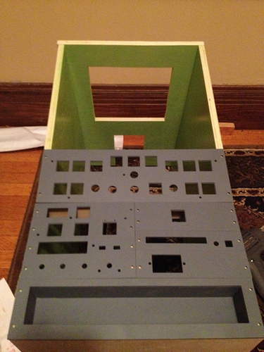
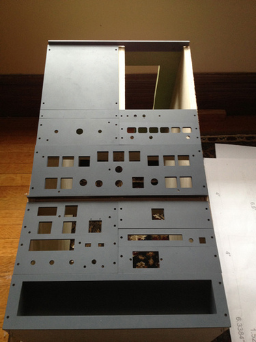
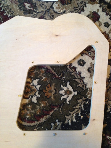
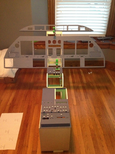
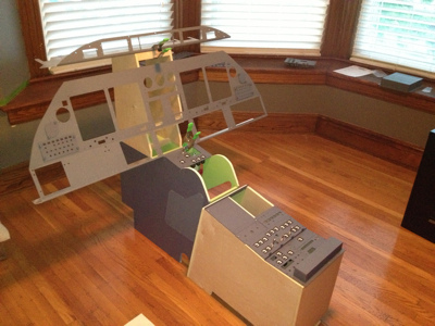
(Original thread started on 06-01-13 by Jeff Lambert) Hey all, I figured its about time to start recording some of my activity on the project. I came to this group a few months back, initially stumbling upon Hangar45 while doing some research on A320's and 737NGs. While both are fantastic aircraft and I hope to someday build my own Airbus and Boeing sims, I really fell in love with the Lear45 and wanted this to be my first experience in the world of sim building. I mean, with all of the support and passion this group has, it's a great place for a newbie to learn the ins and outs. While I do hope to make the experience as real as possible and get into a full shell, I decided that I was going to first start by building the interior furniture from the plans provided on the site. I can tell you that I come from the world of software engineering and while I can program my way in and out of anything, woodworking is definitely NOT my strong suit! I guess that I am however lucky to have a father who has been a general contractor for 30 years so that definitely helps a bit. While the plans are certainly very helpful, I had to have a few goes at certain aspects of the building, mostly the TQ given the arcs and angles and what not. But I think it turned out pretty good: Here I used screw-in female posts to allow for a nice clean threading for the cover panels: UPDATE: I've completed the majority of the painting so far although the above photos don't really show that progress. I've now started on the last piece of woodworking. The monitor support for now until I bite the bullet and get myself a shell kit! I do have a question. I am using the suggested Lenovo and Acer monitors, and have all of the cutouts done but I noticed that there are a few mill points that are complete cut outs. What do you guys suggest or what methods have you used to do the mill-down of those areas primarily where the casings for the monitors are not flush or there is some wiring from the power supplies? (Posted by Will Sasse on 06-01-13) Nice start Jeff, looks like you've got a nice empty area to fill with bits! Reference monitor support, use the drawings as a design starter only. Once you've stripped out your monitors, place them in the required pattern and create a template specific to your monitors. As a computer person you will know that the chances of your monitors fitting an older pattern is slim. Mine started similar to the drawings but now looks nothing like it! Plugs/connectors in different positions was the main issue, then the electronics bay at the back were different sizes.... yada..yada..yada... (Posted by Jeff Lambert on 06-02-13) Thanks for the tips Guys, I did remove the bezels from the monitors an it appears that they do match the original drawings . I was able to place the (upside down) on the wood, trace the needed cutouts and then take care of those with a jig saw. The issue I was faced with was the areas that are Not completely cut out, rather only milled down at the center bottom of the left and right monitors and the right side of the center monitor. I think I,ll try possibly routing out the top layer or two of the ply and see how that works out. I was just curious if others used similar tactics. Trial and error is the name of the game! (Posted by Ron Rollo on 06-04-13) Hey Jeff, Looking good! I actually used a router to do the major cutting and the CNC to do the milling. I will tell you this, my design for the MIP backer has changed so that a lot more of the material is removed. The biggest reason is that I designed a MIP backer that will accept at least two different 15" LCD monitors. The second reason is that there is less milling. So with that said, if you have to, just cut out those areas that have the milling. Just make sure you use supports to give it's strength back. (Posted by Jeff Lambert on 11-13-13) Hey guys, just a quick note to say I haven't vanished. Work has taken me away from play/passion, but who knows, maybe work will allow me to play with this more actively. I would love to have it be my only job at some point! Anyway, I'll be posting some photo updates soon! I've started working again on finishing up mounting the MIP backer and gathering the remaining non-AML switches, pots, encoders etc. I just received a large order from mouser for all of the Molex connectors, pins and quick disconnects for the wiring and finally received my FDS SYS1X High Cap card today. I have a feeling I'll be crimping, soldering and wiring for the next few weeks but having fun doing it! At that point I believe I'll be ready enough to contact Ron to get my shell. I hope I'm still the first in NY to have one. (Posted by Ron Rollo on 11-14-13) Hey Jeff, I sent a shell kit to Buffalo NY but it was picked up and taken across the Canadian board. So I think you will still count as being the first! Molex connectors..... Yes, have fun with that. That's all I will be doing today.. Anyway, looking forward to seeing your progress photos. (Original thread started on 06-01-13 by Jeff Lambert) Hey all, I figured its about time to start recording some of my activity on the project. I came to this group a few months back, initially stumbling upon Hangar45 while doing some research on A320's and 737NGs. While both are fantastic aircraft and I hope to someday build my own Airbus and Boeing sims, I really fell in love with the Lear45 and wanted this to be my first experience in the world of sim building. I mean, with all of the support and passion this group has, it's a great place for a newbie to learn the ins and outs. While I do hope to make the experience as real as possible and get into a full shell, I decided that I was going to first start by building the interior furniture from the plans provided on the site. I can tell you that I come from the world of software engineering and while I can program my way in and out of anything, woodworking is definitely NOT my strong suit! I guess that I am however lucky to have a father who has been a general contractor for 30 years so that definitely helps a bit. While the plans are certainly very helpful, I had to have a few goes at certain aspects of the building, mostly the TQ given the arcs and angles and what not. But I think it turned out pretty good: Here I used screw-in female posts to allow for a nice clean threading for the cover panels: UPDATE: I've completed the majority of the painting so far although the above photos don't really show that progress. I've now started on the last piece of woodworking. The monitor support for now until I bite the bullet and get myself a shell kit! I do have a question. I am using the suggested Lenovo and Acer monitors, and have all of the cutouts done but I noticed that there are a few mill points that are complete cut outs. What do you guys suggest or what methods have you used to do the mill-down of those areas primarily where the casings for the monitors are not flush or there is some wiring from the power supplies? (Posted by Will Sasse on 06-01-13) Nice start Jeff, looks like you've got a nice empty area to fill with bits! Reference monitor support, use the drawings as a design starter only. Once you've stripped out your monitors, place them in the required pattern and create a template specific to your monitors. As a computer person you will know that the chances of your monitors fitting an older pattern is slim. Mine started similar to the drawings but now looks nothing like it! Plugs/connectors in different positions was the main issue, then the electronics bay at the back were different sizes.... yada..yada..yada... (Posted by Jeff Lambert on 06-02-13) Thanks for the tips Guys, I did remove the bezels from the monitors an it appears that they do match the original drawings . I was able to place the (upside down) on the wood, trace the needed cutouts and then take care of those with a jig saw. The issue I was faced with was the areas that are Not completely cut out, rather only milled down at the center bottom of the left and right monitors and the right side of the center monitor. I think I,ll try possibly routing out the top layer or two of the ply and see how that works out. I was just curious if others used similar tactics. Trial and error is the name of the game! (Posted by Ron Rollo on 06-04-13) Hey Jeff, Looking good! I actually used a router to do the major cutting and the CNC to do the milling. I will tell you this, my design for the MIP backer has changed so that a lot more of the material is removed. The biggest reason is that I designed a MIP backer that will accept at least two different 15" LCD monitors. The second reason is that there is less milling. So with that said, if you have to, just cut out those areas that have the milling. Just make sure you use supports to give it's strength back. (Posted by Jeff Lambert on 11-13-13) Hey guys, just a quick note to say I haven't vanished. Work has taken me away from play/passion, but who knows, maybe work will allow me to play with this more actively. I would love to have it be my only job at some point! Anyway, I'll be posting some photo updates soon! I've started working again on finishing up mounting the MIP backer and gathering the remaining non-AML switches, pots, encoders etc. I just received a large order from mouser for all of the Molex connectors, pins and quick disconnects for the wiring and finally received my FDS SYS1X High Cap card today. I have a feeling I'll be crimping, soldering and wiring for the next few weeks but having fun doing it! At that point I believe I'll be ready enough to contact Ron to get my shell. I hope I'm still the first in NY to have one. (Posted by Ron Rollo on 11-14-13) Hey Jeff, I sent a shell kit to Buffalo NY but it was picked up and taken across the Canadian board. So I think you will still count as being the first! Molex connectors..... Yes, have fun with that. That's all I will be doing today.. Anyway, looking forward to seeing your progress photos.Jeff Lambert's Lear45 Project Page
![]()
2017-10-10