


(Original thread started on 07-01-09 by Ron Rollo) Control Columns Part 1: This thread is dedicated to the Project45 version of how to build your own set of dual control columns. All of the parts with the exception of a few custom parts that I can supply you can easily be found at your local hardware stores. The main idea: The columns are designed to function as close to what you would find in the real L45, but accomplished on a shoe string budget. Both the pitch control and the roll control are designed to fall back to their neutral positions if the pilot(s) let go of the yoke(s). As stated in a FLYING MAGAZINE August 1998 article by the author/guest test pilot, “The airplane feels the same at 110 knots indicated as it does at 300.” This works greatly in our favor because we do not have to worry about simulating or modeling the increased load over the control surfaces as airspeed increases. The pivot point falls on top of the base floor but under the “ramped” raised floor. This makes it much easier to access components to the column system without crawling under the base platform. The “dual roll” control lines also fall inside the columns (obviously) and through the cross over member. Believe it or not, I found that braided Nylon rope is the best solution for the roll controls. It is smooth and has a low elasticity meaning it does not stretch when pulled on. UPDATE: The real L45 uses 3.25" O.D. for it's columns! I opted to use PVC that has an O.D. of 2.88" inches for my column set because this was the closest we could find to the correct O.D. in PVC piping. (It should be noted that 2.88" O.D. is known as 2.50" I.D. PVC.) The reason metal piping in the correct size is not used is because of the difficulty in cutting the side access slots with the tool available to us. Some of these earlier photos below show a larger 3.25" PVC pipe used during prototyping that was later replaced with a 2.88" O.D. PVC. A few quick and dirty measurements to keep in mind: 1. The distance from the center of each column is 28 inches. 2. The overall height of the columns is approximately ?? inches from the Base. 3. The forward travel of the control columns is approximately 6 inches. 4. The rear travel of the control columns is approximately 9 inches. Here is a list of parts that you will need to complete the first of two phases of the control columns: (Included in Basic Control Column Kit) Custom made Polly parts for the pivot point “A” frames. Qty 2 Custom made Polly Center Slider Assembly. Qty 2 Plastic bearing sleeve material Qty 2 (Order on line at www.vxb.com) 20mm X 47mm X 14mm Shielded Bearings Qty 4 Product #KIT8469 @ $3.95 each (Items that can be found at your hardware store) 20mm 5 inch bolts Qty 2 20mm nuts Qty 2 20mm lock washers Qty 2 2 inch four way PVC coupling Qty 2 2 inch to 3 inch reducer PVC coupling Qty 2 2 inch to 1.5 inch reducer PVC coupling Qty 2 Patio door rollers (for braided rope in four way) Qty 4 3 inch .25” diameter bolt for roller bearings Qty 4 1 inch .25” I.D. Nylon spacers Qty 10 Misc. washers, spacers and bushings Qty ? Misc PVC parts Here are a few pictures of most of the component listed above. A picture or two, or in this case 20, is worth a thousand words. This is most of the parts you will need to get started: I recommend milling a nice flat area so that the bolts will sit flush. Don't go too deep! Here the patio door rollers are installed inside the four ways. I had to grind the Nylon spacers down a tad to get everything to fit on the bolt: These eye hooks are to help stabilize the columns in their upright position: Here you can see two bearings side by side on a 20mm bolt with locking washers and Nylon washers: To the right is what I call bearing sleeve material. It is needed to take up the slack between the bearings and the inside wall of the PVC part. I also include this in the Column kits: Here is a picture of the sub assemblies ready to be mounted onto the cross over member: If you look closely, you can see what I call the bearing sleeve inside this unit: Here is the cross over assembly unit built up. The couplings you see in the center of this cross over had to be modified to slip all the way down to the center. I had to use a Dremel tool to remove the catch that is located on the inside, in the middle of the couplings. I recommend using glue on as few parts as possible. You can see that I used screws for most of the big parts: These parts MUST be square and level, otherwise you know what your gonna get. Holes in your base floor are a must with this unit. So I hope you have a base platform of some sort built up and ready to go: This is a diagram of how the units attach to the cross over assembly. Notice that the bottom 90 degrees has been removed in this drawing and on my parts in the next picture. This allows you to slip the parts on and off without removing the whole Column System. If you choose, you can leave it in a full circle for a stronger unit: NOTE: This design has been updated! I went an extra step and used to "U" brackets to help hold the column system in place. I also plan to use Petroleum Jelly between the "U" brackets and the column system to help reduce friction. That's why I have an aluminum plate under this area to act as a catch: I built this contraption for the column system to attach to on the bottom side: I use two medium duty spring per side to assist in holding the column system upright. The amount of springs used may change after I add the weight of the yokes and other misc items to the column system: Whether you have a shell or not, I highly recommend that you build yourself a raised floor section that mimics the real L45 aircraft. (You have to anyway so that the column system is hidden!) Here you can see the Copilots side raised pedal floor. I built these white tabs on the front of it to help support the "Ramped" floor that covers the column system: Here you can see how everything is working in harmony: Please keep in mind that most of these pieces will need to be fabricated to some degree. Unfortunately, there is no such thing as a “Learjet Super Store” so we must improvise. NOTE: Don’t glue the PVC together like you normally would with a plumbing job. Instead, use as many as eight screws per connection to hold the pieces together. NOTE: You will have to shave down a few of the Nylon bushing to get them to fit properly especially on the ROLL bearings in the four way. Remember, your personal build does not have to be exactly like my design. This information is intended to be ideas for you to use so that you can build your own set of Control Columns! If you have questions or need pointers, please feel free to contact me. Scott, my "beta builder", for the life of him could not find one of the key elements to this build up in the big city of Chicago Illinois. It is a PVC coupling designed to glue a 2 inch pipe to a 1 1/2 inch pipe, or in other words a reducer. I found two types of reducers that will do the job. If you can find the deeper version, use it because it will add strength. The deeper version will require two of the smaller bearings each. The smaller version needs only one bearing, but it is actually more expensive than two of them together!
(Original thread started on 07-01-09 by Ron Rollo) Control Columns Part 1: This thread is dedicated to the Project45 version of how to build your own set of dual control columns. All of the parts with the exception of a few custom parts that I can supply you can easily be found at your local hardware stores. The main idea: The columns are designed to function as close to what you would find in the real L45, but accomplished on a shoe string budget. Both the pitch control and the roll control are designed to fall back to their neutral positions if the pilot(s) let go of the yoke(s). As stated in a FLYING MAGAZINE August 1998 article by the author/guest test pilot, “The airplane feels the same at 110 knots indicated as it does at 300.” This works greatly in our favor because we do not have to worry about simulating or modeling the increased load over the control surfaces as airspeed increases. The pivot point falls on top of the base floor but under the “ramped” raised floor. This makes it much easier to access components to the column system without crawling under the base platform. The “dual roll” control lines also fall inside the columns (obviously) and through the cross over member. Believe it or not, I found that braided Nylon rope is the best solution for the roll controls. It is smooth and has a low elasticity meaning it does not stretch when pulled on. UPDATE: The real L45 uses 3.25" O.D. for it's columns! I opted to use PVC that has an O.D. of 2.88" inches for my column set because this was the closest we could find to the correct O.D. in PVC piping. (It should be noted that 2.88" O.D. is known as 2.50" I.D. PVC.) The reason metal piping in the correct size is not used is because of the difficulty in cutting the side access slots with the tool available to us. Some of these earlier photos below show a larger 3.25" PVC pipe used during prototyping that was later replaced with a 2.88" O.D. PVC. A few quick and dirty measurements to keep in mind: 1. The distance from the center of each column is 28 inches. 2. The overall height of the columns is approximately ?? inches from the Base. 3. The forward travel of the control columns is approximately 6 inches. 4. The rear travel of the control columns is approximately 9 inches. Here is a list of parts that you will need to complete the first of two phases of the control columns: (Included in Basic Control Column Kit) Custom made Polly parts for the pivot point “A” frames. Qty 2 Custom made Polly Center Slider Assembly. Qty 2 Plastic bearing sleeve material Qty 2 (Order on line at http://www.vxb.com) 20mm X 47mm X 14mm Shielded Bearings Qty 4 Product #KIT8469 @ $3.95 each (Items that can be found at your hardware store) 20mm 5 inch bolts Qty 2 20mm nuts Qty 2 20mm lock washers Qty 2 2 inch four way PVC coupling Qty 2 2 inch to 3 inch reducer PVC coupling Qty 2 2 inch to 1.5 inch reducer PVC coupling Qty 2 Patio door rollers (for braided rope in four way) Qty 4 3 inch .25” diameter bolt for roller bearings Qty 4 1 inch .25” I.D. Nylon spacers Qty 10 Misc. washers, spacers and bushings Qty ? Misc PVC parts Here are a few pictures of most of the component listed above. A picture or two, or in this case 20, is worth a thousand words. This is most of the parts you will need to get started: I recommend milling a nice flat area so that the bolts will sit flush. Don't go too deep! Here the patio door rollers are installed inside the four ways. I had to grind the Nylon spacers down a tad to get everything to fit on the bolt: These eye hooks are to help stabilize the columns in their upright position: Here you can see two bearings side by side on a 20mm bolt with locking washers and Nylon washers: To the right is what I call bearing sleeve material. It is needed to take up the slack between the bearings and the inside wall of the PVC part. I also include this in the Column kits: Here is a picture of the sub assemblies ready to be mounted onto the cross over member: If you look closely, you can see what I call the bearing sleeve inside this unit: Here is the cross over assembly unit built up. The couplings you see in the center of this cross over had to be modified to slip all the way down to the center. I had to use a Dremel tool to remove the catch that is located on the inside, in the middle of the couplings. I recommend using glue on as few parts as possible. You can see that I used screws for most of the big parts: These parts MUST be square and level, otherwise you know what your gonna get. Holes in your base floor are a must with this unit. So I hope you have a base platform of some sort built up and ready to go: This is a diagram of how the units attach to the cross over assembly. Notice that the bottom 90 degrees has been removed in this drawing and on my parts in the next picture. This allows you to slip the parts on and off without removing the whole Column System. If you choose, you can leave it in a full circle for a stronger unit: NOTE: This design has been updated! I went an extra step and used to "U" brackets to help hold the column system in place. I also plan to use Petroleum Jelly between the "U" brackets and the column system to help reduce friction. That's why I have an aluminum plate under this area to act as a catch: I built this contraption for the column system to attach to on the bottom side: I use two medium duty spring per side to assist in holding the column system upright. The amount of springs used may change after I add the weight of the yokes and other misc items to the column system: Whether you have a shell or not, I highly recommend that you build yourself a raised floor section that mimics the real L45 aircraft. (You have to anyway so that the column system is hidden!) Here you can see the Copilots side raised pedal floor. I built these white tabs on the front of it to help support the "Ramped" floor that covers the column system: Here you can see how everything is working in harmony: Please keep in mind that most of these pieces will need to be fabricated to some degree. Unfortunately, there is no such thing as a “Learjet Super Store” so we must improvise. NOTE: Don’t glue the PVC together like you normally would with a plumbing job. Instead, use as many as eight screws per connection to hold the pieces together. NOTE: You will have to shave down a few of the Nylon bushing to get them to fit properly especially on the ROLL bearings in the four way. Remember, your personal build does not have to be exactly like my design. This information is intended to be ideas for you to use so that you can build your own set of Control Columns! If you have questions or need pointers, please feel free to contact me. Scott, my "beta builder", for the life of him could not find one of the key elements to this build up in the big city of Chicago Illinois. It is a PVC coupling designed to glue a 2 inch pipe to a 1 1/2 inch pipe, or in other words a reducer. I found two types of reducers that will do the job. If you can find the deeper version, use it because it will add strength. The deeper version will require two of the smaller bearings each. The smaller version needs only one bearing, but it is actually more expensive than two of them together!
(Posted by Ron Rollo on 04-13-12) UPDATE: On the Lower Column assembly! Thanks to Steve in Canada who wanted a built up set of the lower column assembly, it gave me a chance to add all of the changes that I have wanted to make all in one set. I was also able to determine exactly how much time, material and parts go into this contraption to put a price tag on the completed lower column set like you see here: If your interested in the completed set like this, it is $445. Other wise, the Poly material kit is $50. One of the major changes is the way I secure the center of the crossover to prevent play, sway and slop. (This will work great for the 737 guys like Scott and Tom!) I am using Poly to secure it to the base floor. This idea came from Ronald Pater. You will also notice that I took out the slider notches, they are no longer needed: Here the columns are up side down to show this part a little better: I am not sure if the additional springs under the base frame are needed any longer but just in case they are, I still have the eye hook in the design: Nothing new inside the columns but I thought I would show it again anyway: I am still using two shielded bearings stacked side by side in the crossover ends. This makes for a smooth pivot point: And here is a photo of the lower column system by itself: Here is the updated version of the Poly lower column kit for $55 plus shipping: If interested in this set, just email me. (Posted by Randy Buchanan on 05-12-12) I was going to say eat your heart out look at what I just bought! I thought Mike bought it at first. But not to be. This bad boy is $10,000.00. But at least we have a nice picture. This might be helpful because some of us Ron are very good at extracting dimensions from pictures. There are some other details here as well. Enjoy. (Posted by Ron Rollo on 05-13-12) Alan suggested using a smaller diameter pipe for our columns. After further research, I determined that 2.5” diameter pipe is a more appropriate fit for our columns. Thanks to Alan for pointing this out! I went ahead and placed an order for some fittings and the 2.5" pipe. You only need the two foot long pipe for each column. You can get 2.5" PVC pipe is available here: http://www.usplastic.com/catalog/item.aspx?itemid=38257&catid=727 (Posted by Alan Norris on 05-21-12) I just received my 2-1/2" pipe and I must say it looks a whole lot more appropriate than the 3". I always thought that the 3" looked too large so I'm glad I asked the question. With the weight of the pipe I think I either need stronger springs or I need to put more tension on them as the column does not go back to center quickly enough and it will only be worse once the weight of the yoke is added. Do you think it's because I didn't have the under floor spring system in my sim that is causing this? (Posted by Ron Rollo on 05-21-12) Yes, you need the springs under the floor. Or in your case, stronger or double the springs. I got my 2.5" pipe today and it does look more to scale. Of course I have always known it was over scale but just never bothered to hunt down 2.5" pipe. And yes, it is super thick and strong. Twice as thick as the 3" pipe. (Posted by Ron Rollo on 05-23-12) I have the parts just kinda laying in there. Some things, like the POT, are not exactly where they will be in the column. So don't get too excited. And, these pieces are all made of MDF which would be the JIGS for the column heads. The final pieces will be made of black .5" Polly (plastic) material: Here are the new 2.5" columns: And here is the knuckle where the column meets the lower column assembly: (Posted by Eric Tomlin on 05-23-12) Last week I received the issue of Flying Magazine that debuted the Learjet 45- it was from 1998. The article was mostly information that most here already know about, but one thing that was mentioned that I had never read before was the fact that the aileron movement felt basically the same at any airspeed, where as many aircraft that have cable connected control surfaces, obviously have a noticeable effect as the airspeed goes higher. The reason given for the ailerons feeling relatively light across the airspeed spectrum was due to the spoilerons (spoilers moving to aid the ailerons) activating beyond a certain about of roll input. What does this mean to us sim builders? Well, to me it means that having a relatively light control load on your aileron axis when your building the yoke and column system is much easier to model than trying to invent some complicated device that increases the load as airspeed increases. Just one more reason why the LJ45 is such a great home built sim project! (Posted by Ron Rollo on 05-25-12) Here is a close up photo of the information stuck on the side of the shakers: You can check out the Stick Shaker thread HERE Sometimes we buy these things blind with our fingers crossed. Sometimes they work for our needs and sometimes they don't. The AOA gauges are another great example. I have a pair that are completely useless. In any case, I hope this information helps. I don't think you can go wrong with these. The only issue is I have to make a bracket to hang it on. The other issue is that it is 27.5 volts which actually works out better for us as Eric pointed out. We are building simulators and they are no where near as solidly built as the real planes. So having the shakers running at half power might be a good thing. Have we ever got a straight answer on how thick the columns are? I ask this because we have been told by "big hat no cattle guy" that the columns were 2.5 wide. Well, the issue there is he measured a Lear35 column. And they appear to be smaller than the Lear45 columns. Lear35 yoke and column head: Lear45 yoke and column head: Lear45 bare columns: Photo of my sim with 2.5" I.D. on the left (3" O.D.) and 3" I.D. on the right, (3.5" O.D.): (The column on the left is correct!) We are good with the 2.5" I.D. pipe that we are using but we need to start calling with 3" O.D. columns. When you compare these photos, does the one on the left look more to scale or the one on the right? (Posted by Eric Tomlin on 05-31-12) I think that the smaller pipe looks better and falls somewhere between the real LJ35 size and your previous pipe size. When sitting in the Project45 sim, I felt that the columns were a tad too big and from photos your new pipe looks more scale to me, but I agree that the 35 columns are definitely narrower then the 45. Here's where we need to make a good compromise. You are the one building these so I defer to you in this particular case! (Posted by Randy Buchanan on 05-31-12) What we need is the actual out side dimension of the lear45 column right? Not the Lear 35. I can ask my sales friend to put a tape on it or we can use the photo you have and measure it ourselves. This would be the objective approach. Let me work on this today come up with an answer and a photo to prove it. So after doing the scale work. If the TQ is 8.25 and the center console is 11.5 per Ron and Eric's drawings and you also know that the center plane of the columns is in the plane as where the throttles are at idle then the columns are exactly 2.75" outside dimension. I am sure nobody is going to like that, but that is scale and Eric you are right the right seems too big and the left is smaller. But at 3" OD is closer to 2.75 than 3.5. Now what? My vote is to use the one on the left. We can keep the 2.75 as a dirty little secret. (Posted by Ron Rollo on 06-01-12) This all makes me feel better. The one on the left is even too big if you can believe that! But only by 1/8" inch. The one on the left is 2.875" O.D. I have started the column heads and I can tell you that they are turning out nice. I will offer them in kit form to keep the cost down for those of you on a budget and then also offer them completed for those of you who have less time to dedicate to the building process. I should have some photos of the prototype tonight. As of right now, everything that I am doing is designed for the real Lear35 yokes. Over the past few days I have restarted the work on the column heads and if nothing else, I am very clear on the direction I am going and what it is going to take to make these things. My goal is to make something that works and looks like the real part as close as possible anyway. I started off by making a wooden prototype of the column head to prove that the design is sound. I had to make a few changes but that occurred in CAD: I then went into CAD and drew everything up. Today I cut those pieces out in .25" cast to see what they would look like: I had to order some longer end mill bits to cut through the .5" black Poly (plastic) material. Here is a photo of a piece that was cut partially just to insure that the material is suitable for milling, which it is: We are on the right track and I plan to make 8 sets in the next two month. I will be back at it next Thursday and hope to at least snap a photo of a pair of yokes hanging in my sim! (Posted by Ron Rollo on 04-13-12) UPDATE: On the Lower Column assembly! Thanks to Steve in Canada who wanted a built up set of the lower column assembly, it gave me a chance to add all of the changes that I have wanted to make all in one set. I was also able to determine exactly how much time, material and parts go into this contraption to put a price tag on the completed lower column set like you see here: If your interested in the completed set like this, it is $445. Other wise, the Poly material kit is $50. One of the major changes is the way I secure the center of the crossover to prevent play, sway and slop. (This will work great for the 737 guys like Scott and Tom!) I am using Poly to secure it to the base floor. This idea came from Ronald Pater. You will also notice that I took out the slider notches, they are no longer needed: Here the columns are up side down to show this part a little better: I am not sure if the additional springs under the base frame are needed any longer but just in case they are, I still have the eye hook in the design: Nothing new inside the columns but I thought I would show it again anyway: I am still using two shielded bearings stacked side by side in the crossover ends. This makes for a smooth pivot point: And here is a photo of the lower column system by itself: Here is the updated version of the Poly lower column kit for $55 plus shipping: If interested in this set, just email me. (Posted by Randy Buchanan on 05-12-12) I was going to say eat your heart out look at what I just bought! I thought Mike bought it at first. But not to be. This bad boy is $10,000.00. But at least we have a nice picture. This might be helpful because some of us Ron are very good at extracting dimensions from pictures. There are some other details here as well. Enjoy. (Posted by Ron Rollo on 05-13-12) Alan suggested using a smaller diameter pipe for our columns. After further research, I determined that 2.5” diameter pipe is a more appropriate fit for our columns. Thanks to Alan for pointing this out! I went ahead and placed an order for some fittings and the 2.5" pipe. You only need the two foot long pipe for each column. You can get 2.5" PVC pipe is available here: http://www.usplastic.com/catalog/item.aspx?itemid=38257&catid=727 (Posted by Alan Norris on 05-21-12) I just received my 2-1/2" pipe and I must say it looks a whole lot more appropriate than the 3". I always thought that the 3" looked too large so I'm glad I asked the question. With the weight of the pipe I think I either need stronger springs or I need to put more tension on them as the column does not go back to center quickly enough and it will only be worse once the weight of the yoke is added. Do you think it's because I didn't have the under floor spring system in my sim that is causing this? (Posted by Ron Rollo on 05-21-12) Yes, you need the springs under the floor. Or in your case, stronger or double the springs. I got my 2.5" pipe today and it does look more to scale. Of course I have always known it was over scale but just never bothered to hunt down 2.5" pipe. And yes, it is super thick and strong. Twice as thick as the 3" pipe. (Posted by Ron Rollo on 05-23-12) I have the parts just kinda laying in there. Some things, like the POT, are not exactly where they will be in the column. So don't get too excited. And, these pieces are all made of MDF which would be the JIGS for the column heads. The final pieces will be made of black .5" Polly (plastic) material: Here are the new 2.5" columns: And here is the knuckle where the column meets the lower column assembly: (Posted by Eric Tomlin on 05-23-12) Last week I received the issue of Flying Magazine that debuted the Learjet 45- it was from 1998. The article was mostly information that most here already know about, but one thing that was mentioned that I had never read before was the fact that the aileron movement felt basically the same at any airspeed, where as many aircraft that have cable connected control surfaces, obviously have a noticeable effect as the airspeed goes higher. The reason given for the ailerons feeling relatively light across the airspeed spectrum was due to the spoilerons (spoilers moving to aid the ailerons) activating beyond a certain about of roll input. What does this mean to us sim builders? Well, to me it means that having a relatively light control load on your aileron axis when your building the yoke and column system is much easier to model than trying to invent some complicated device that increases the load as airspeed increases. Just one more reason why the LJ45 is such a great home built sim project! (Posted by Ron Rollo on 05-25-12) Here is a close up photo of the information stuck on the side of the shakers: You can check out the Stick Shaker thread HERE Sometimes we buy these things blind with our fingers crossed. Sometimes they work for our needs and sometimes they don't. The AOA gauges are another great example. I have a pair that are completely useless. In any case, I hope this information helps. I don't think you can go wrong with these. The only issue is I have to make a bracket to hang it on. The other issue is that it is 27.5 volts which actually works out better for us as Eric pointed out. We are building simulators and they are no where near as solidly built as the real planes. So having the shakers running at half power might be a good thing. Have we ever got a straight answer on how thick the columns are? I ask this because we have been told by "big hat no cattle guy" that the columns were 2.5 wide. Well, the issue there is he measured a Lear35 column. And they appear to be smaller than the Lear45 columns. Lear35 yoke and column head: Lear45 yoke and column head: Lear45 bare columns: Photo of my sim with 2.5" I.D. on the left (3" O.D.) and 3" I.D. on the right, (3.5" O.D.): (The column on the left is correct!) We are good with the 2.5" I.D. pipe that we are using but we need to start calling with 3" O.D. columns. When you compare these photos, does the one on the left look more to scale or the one on the right? (Posted by Eric Tomlin on 05-31-12) I think that the smaller pipe looks better and falls somewhere between the real LJ35 size and your previous pipe size. When sitting in the Project45 sim, I felt that the columns were a tad too big and from photos your new pipe looks more scale to me, but I agree that the 35 columns are definitely narrower then the 45. Here's where we need to make a good compromise. You are the one building these so I defer to you in this particular case! (Posted by Randy Buchanan on 05-31-12) What we need is the actual out side dimension of the lear45 column right? Not the Lear 35. I can ask my sales friend to put a tape on it or we can use the photo you have and measure it ourselves. This would be the objective approach. Let me work on this today come up with an answer and a photo to prove it. So after doing the scale work. If the TQ is 8.25 and the center console is 11.5 per Ron and Eric's drawings and you also know that the center plane of the columns is in the plane as where the throttles are at idle then the columns are exactly 2.75" outside dimension. I am sure nobody is going to like that, but that is scale and Eric you are right the right seems too big and the left is smaller. But at 3" OD is closer to 2.75 than 3.5. Now what? My vote is to use the one on the left. We can keep the 2.75 as a dirty little secret. (Posted by Ron Rollo on 06-01-12) This all makes me feel better. The one on the left is even too big if you can believe that! But only by 1/8" inch. The one on the left is 2.875" O.D. I have started the column heads and I can tell you that they are turning out nice. I will offer them in kit form to keep the cost down for those of you on a budget and then also offer them completed for those of you who have less time to dedicate to the building process. I should have some photos of the prototype tonight. As of right now, everything that I am doing is designed for the real Lear35 yokes. Over the past few days I have restarted the work on the column heads and if nothing else, I am very clear on the direction I am going and what it is going to take to make these things. My goal is to make something that works and looks like the real part as close as possible anyway. I started off by making a wooden prototype of the column head to prove that the design is sound. I had to make a few changes but that occurred in CAD: I then went into CAD and drew everything up. Today I cut those pieces out in .25" cast to see what they would look like: I had to order some longer end mill bits to cut through the .5" black Poly (plastic) material. Here is a photo of a piece that was cut partially just to insure that the material is suitable for milling, which it is: We are on the right track and I plan to make 8 sets in the next two month. I will be back at it next Thursday and hope to at least snap a photo of a pair of yokes hanging in my sim! (Posted by Ron Rollo on 06-11-12) Things are going better than I could have hoped for. Usually by now, I have to go back and totally redesign everything to get it to work right. But even then, I have made small changes to the column heads at least four times this week. Here are a few photos of the progress: In these photos, you can see the bearings, bearing stops, turn stops, Pots, etc: Wooden plugs for the fiberglass work next week: Kinda how it is going to look. It is actually going to fit all the way to front edge of the column head. The other plug is sitting upside down and goes on the under side: And a test fit to fine tune the column height: I am using what they call 2.5" PVC pipe. But what 2.5" means is the I.D., and even with the PVC thick wall that I am using, it does not measure up to 2.5". It is actually more like 2 5/16". Anyway, what is important to us is the O.D. In this case, the 2.5" pipe has a O.D. of 2 7/8", which looks and feels right. To answer the question about the way the yoke attaches to the column head shaft: I would love to use a sprocket type mount just as the real yokes use. But in an effort to keep it simple and keep the price and time down, I have opted to use wooden dowels and spindles. Here's the thing, this thing is not leaving the ground and it does not have to withstand the forces of two grown men pulling on the yokes with all their might to avoid either a mid air or an untimely landing. Therefor, we can ease back on the engineering! So as of right now, the plan is to use wood, which has many benefits. It is super easy to drill holes into it to tie the two pieces together and to attach things like the turn stops, spring eyelet and hole for the POT at the rear end. Here are a few of the latest photos: This photo shows the access hole for the set screw that hold the yoke onto the shaft: This is a very important addition that I came up with just a few days ago because it enables us to remove the yoke without totally taking the column heads apart. For you guys like Alan who only need one yoke, there is not much more to it that what you see here in these photos. Although they still need the stops and spring installed. (Posted by Eric Tomlin on 06-14-12) I agree with Ron that there's no need to over-engineer this thing, but the concern with wood more than strength is wear, as in where the wood makes contact with wire rope/nylon rope/bearings. However, I know that once you get it fully working and get it all setup with expected forces/moments, then you can truly make a good assessment and make adjustments as needed. I'm just glad you're taking it on and offering it to others! (Posted by Ron Rollo on 06-14-12) When I say "Iron wood", I mean it is as strong as steel. It is after all just a 89 cent dowel. But strong! As for wear concerns, it rides in two sealed bearings. So there is no wearing issues to worry about. I also found the perfect spring that returns the yokes to center. I promised a few things so here they are. Here is a photo of my father manning the CNC machine. He cut out five sets! This is a photo of the mother load / work station. It looks like a lot but it is actually only eight sets. I made a few design changes that are notable. First off, I decided to go with black Acetal plastic 5/8" diameter rods instead of the wood dowels. The wooden dowels are plenty strong enough and if I was only building one or two sets, I would probably stick with them. But the issue is they are not consistent and or perfectly round. My hopes are that the plastic rods are perfectly rounds AND strong. They should arrive in the next day or two: The other update that I actually put into the design last week is a set of threaded rods that pull the entire thing together. The way I have designed the bearing spacers is so that they ride and press only on the bearing lip so that it does not interfere with the smooth turning that we want. We can tighten these rods as tight as we want (without getting carried away) and it will not interfere with the bearings and the job they do: I was having a hard time increasing the holes in the spindles from 3/8" to 5/8" to the point that I went out and spent some big bucks on a lathe machine. But after 24 hours of thought, I decided to return it and try a few other methods to increase the hole. The issue is we have to have the hole as close to the center as possible. At the rate I am successful in making a perfect hole, I will end up screwing up one for every one that is good. Still far cheaper than purchasing a Lathe machine that I will never need again. Next week I will have the rods, spindles, stops and springs installed. I should also have the brackets made that attached the column head to the column. (Posted by Ron Rollo on 06-11-12) Things are going better than I could have hoped for. Usually by now, I have to go back and totally redesign everything to get it to work right. But even then, I have made small changes to the column heads at least four times this week. Here are a few photos of the progress: In these photos, you can see the bearings, bearing stops, turn stops, Pots, etc: Wooden plugs for the fiberglass work next week: Kinda how it is going to look. It is actually going to fit all the way to front edge of the column head. The other plug is sitting upside down and goes on the under side: And a test fit to fine tune the column height: I am using what they call 2.5" PVC pipe. But what 2.5" means is the I.D., and even with the PVC thick wall that I am using, it does not measure up to 2.5". It is actually more like 2 5/16". Anyway, what is important to us is the O.D. In this case, the 2.5" pipe has a O.D. of 2 7/8", which looks and feels right. To answer the question about the way the yoke attaches to the column head shaft: I would love to use a sprocket type mount just as the real yokes use. But in an effort to keep it simple and keep the price and time down, I have opted to use wooden dowels and spindles. Here's the thing, this thing is not leaving the ground and it does not have to withstand the forces of two grown men pulling on the yokes with all their might to avoid either a mid air or an untimely landing. Therefor, we can ease back on the engineering! So as of right now, the plan is to use wood, which has many benefits. It is super easy to drill holes into it to tie the two pieces together and to attach things like the turn stops, spring eyelet and hole for the POT at the rear end. Here are a few of the latest photos: This photo shows the access hole for the set screw that hold the yoke onto the shaft: This is a very important addition that I came up with just a few days ago because it enables us to remove the yoke without totally taking the column heads apart. For you guys like Alan who only need one yoke, there is not much more to it that what you see here in these photos. Although they still need the stops and spring installed. (Posted by Eric Tomlin on 06-14-12) I agree with Ron that there's no need to over-engineer this thing, but the concern with wood more than strength is wear, as in where the wood makes contact with wire rope/nylon rope/bearings. However, I know that once you get it fully working and get it all setup with expected forces/moments, then you can truly make a good assessment and make adjustments as needed. I'm just glad you're taking it on and offering it to others! (Posted by Ron Rollo on 06-14-12) When I say "Iron wood", I mean it is as strong as steel. It is after all just a 89 cent dowel. But strong! As for wear concerns, it rides in two sealed bearings. So there is no wearing issues to worry about. I also found the perfect spring that returns the yokes to center. I promised a few things so here they are. Here is a photo of my father manning the CNC machine. He cut out five sets! This is a photo of the mother load / work station. It looks like a lot but it is actually only eight sets. I made a few design changes that are notable. First off, I decided to go with black Acetal plastic 5/8" diameter rods instead of the wood dowels. The wooden dowels are plenty strong enough and if I was only building one or two sets, I would probably stick with them. But the issue is they are not consistent and or perfectly round. My hopes are that the plastic rods are perfectly rounds AND strong. They should arrive in the next day or two: The other update that I actually put into the design last week is a set of threaded rods that pull the entire thing together. The way I have designed the bearing spacers is so that they ride and press only on the bearing lip so that it does not interfere with the smooth turning that we want. We can tighten these rods as tight as we want (without getting carried away) and it will not interfere with the bearings and the job they do: I was having a hard time increasing the holes in the spindles from 3/8" to 5/8" to the point that I went out and spent some big bucks on a lathe machine. But after 24 hours of thought, I decided to return it and try a few other methods to increase the hole. The issue is we have to have the hole as close to the center as possible. At the rate I am successful in making a perfect hole, I will end up screwing up one for every one that is good. Still far cheaper than purchasing a Lathe machine that I will never need again. Next week I will have the rods, spindles, stops and springs installed. I should also have the brackets made that attached the column head to the column. (Posted by Ron Rollo on 06-15-12) Here is a quick tutorial for the guys with CNC's and who want to cut the access holes in your columns: In case you have no idea what I am talking about, there are two slots on each side of the columns that allows us to access the cables and stuff for adjusting: The first thing I did was think up a plan and made two mounts for the column to lay onto: You can either draw something up like this yourself or I can send you the drawing and or G code. Because I am a nut for attention to detail, I am lining up the coupling so that the points are straight: I am using the lower portion of my mount to tell me where the center of the column is. The other end will match up perfectly. Which reminds me, you obviously have to make sure that the mounts are square on your CNC board. I used L angle to draw a straight line between the two marks. L angel as you can see in the photo works much better than a regular ruler would on a tube like this: After spending some time scaling, gauging and guessing, I determined that the length of the opening will be 4 inches from the top of the column and 4 inches from the top of the coupling at the bottom. Again, I used a piece of L angle but this time I cut it down to the size of the hole that I needed. The width of the opening will be right at one inch wide: Here is another neat little trick that I found will help make a straight line on a tube. I used the top half of the mount to mark the ends of the opening: Now that I have everything marked, it's time to mount the column to the mounts. Mine turned out perfect and the mounts hold the column nice and snug, but when I need to, I can still rotate the column to get to the second part of the cut: If yours turn out to be too loose, sand the flat joints to make the mounts tighter. The CNC in action: There is no G code for this, it's all manual movements. I am using a 1/8th inch double flute bit and I slowed the jog rate down to 20IPM to make sure I don't break a bit or screw up. What I did was ran one pass down one of the long lines about .15" deep. Then cut part of the end lines. I then ran it back .32" deep down the same long line which finishes the cut. Again, I do part of the end line while the column is in the STOP position. At this point, I move the CNC up and out of the way and rotate the column so that the other long line is at top dead center. (Don't get this confused with the other opening 180 degree opposite of this first opening) Bring the CNC back into play and complete the cut out repeating the steps above. I also found that zeroing out all the axis makes things easier. You can stop the bit within .001 of the start point and do another direction and be right on the money. It has to be done like this if you want the cuts pointing to the imaginary line running through the center of the column. (You guys who have CNC's know all this I am sure) Here is an access opening freshly cut. Notice that I rotated the column? I did most of my prep sanding while the column was still in the mounts: And here are two columns with two access holes cut in each of them: Recently I completed my set of columns and found the best way to do a few things, including mounting the column heads to the columns, making the access covers, building a version of the stick shaker mounting bracket and fitting in a mic jack. Here are the columns pretty much ready to be installed in the sim: I have the column heads just sitting on top of the columns in this photo. Each column head will be held in place by four screws: These are dummy screws that do nothing but look like the are doing something: These are the mic jacks. I hope that the mic jack body does not get in the way of the cables. I don't think that they will: I have two stick shakers that are different than what some of the other guys have so this mounting system may not work for anyone else. I'll have the stick shakers painted and mounted next week: The access covers as I pointed out in one of my previous post were kinda difficult to to make because they have to be curved and then cut. Bending and curving is easy. Cutting them is the hard part: Here is one of those moments I have been waiting for: (Although the roll is not connected yet.) I have to work on the wiring coming out of the yokes first. To see how that is done check this thread out HERE A cool shot from outside the cockpit: While I was at it, I refinished the chart holders and added some longer wire. I am hoping that there are two unused wires in the yoke harness that I can tie into. Otherwise I will have two additional wires running through the turn slot: I have the stick shakers repainted and mounted. I hope my stick shaker mount holds up to the violence. Also in this photo you can see my little rubber stop that keep the column head from crashing into the DU's. You can also put a stop down at the base of the column: I also have the access covers on the columns. It may be several weeks before I get back to work on them so I thought that they might as well look good setting there: I did a little test feeling of the columns now that they have 95% of their weight on them. They feel really good and the columns spring back to center and stops. If I can find a way, I will probably add a few more springs. Right now it kinda feels like power steering in a Cadillac, which feels great but I am thinking that there should be a little more resistance. From the top of the column head covers to the bottom of the MIP, (or the bottom of the lower panels), is approximately 10 inches. And this is when they are sitting straight up and down. (Posted By Alan Norris on 07-16-12) SWEET. I was wondering what the switch on the top right of the yoke does. I have all my other switches installed but cannot figure out what this one does. (Posted by Ron Rollo on 06-15-12) Here is a quick tutorial for the guys with CNC's and who want to cut the access holes in your columns: In case you have no idea what I am talking about, there are two slots on each side of the columns that allows us to access the cables and stuff for adjusting: The first thing I did was think up a plan and made two mounts for the column to lay onto: You can either draw something up like this yourself or I can send you the drawing and or G code. Because I am a nut for attention to detail, I am lining up the coupling so that the points are straight: I am using the lower portion of my mount to tell me where the center of the column is. The other end will match up perfectly. Which reminds me, you obviously have to make sure that the mounts are square on your CNC board. I used L angle to draw a straight line between the two marks. L angel as you can see in the photo works much better than a regular ruler would on a tube like this: After spending some time scaling, gauging and guessing, I determined that the length of the opening will be 4 inches from the top of the column and 4 inches from the top of the coupling at the bottom. Again, I used a piece of L angle but this time I cut it down to the size of the hole that I needed. The width of the opening will be right at one inch wide: Here is another neat little trick that I found will help make a straight line on a tube. I used the top half of the mount to mark the ends of the opening: Now that I have everything marked, it's time to mount the column to the mounts. Mine turned out perfect and the mounts hold the column nice and snug, but when I need to, I can still rotate the column to get to the second part of the cut: If yours turn out to be too loose, sand the flat joints to make the mounts tighter. The CNC in action: There is no G code for this, it's all manual movements. I am using a 1/8th inch double flute bit and I slowed the jog rate down to 20IPM to make sure I don't break a bit or screw up. What I did was ran one pass down one of the long lines about .15" deep. Then cut part of the end lines. I then ran it back .32" deep down the same long line which finishes the cut. Again, I do part of the end line while the column is in the STOP position. At this point, I move the CNC up and out of the way and rotate the column so that the other long line is at top dead center. (Don't get this confused with the other opening 180 degree opposite of this first opening) Bring the CNC back into play and complete the cut out repeating the steps above. I also found that zeroing out all the axis makes things easier. You can stop the bit within .001 of the start point and do another direction and be right on the money. It has to be done like this if you want the cuts pointing to the imaginary line running through the center of the column. (You guys who have CNC's know all this I am sure) Here is an access opening freshly cut. Notice that I rotated the column? I did most of my prep sanding while the column was still in the mounts: And here are two columns with two access holes cut in each of them: Recently I completed my set of columns and found the best way to do a few things, including mounting the column heads to the columns, making the access covers, building a version of the stick shaker mounting bracket and fitting in a mic jack. Here are the columns pretty much ready to be installed in the sim: I have the column heads just sitting on top of the columns in this photo. Each column head will be held in place by four screws: These are dummy screws that do nothing but look like the are doing something: These are the mic jacks. I hope that the mic jack body does not get in the way of the cables. I don't think that they will: I have two stick shakers that are different than what some of the other guys have so this mounting system may not work for anyone else. I'll have the stick shakers painted and mounted next week: The access covers as I pointed out in one of my previous post were kinda difficult to to make because they have to be curved and then cut. Bending and curving is easy. Cutting them is the hard part: Here is one of those moments I have been waiting for: (Although the roll is not connected yet.) I have to work on the wiring coming out of the yokes first. To see how that is done check this thread out HERE A cool shot from outside the cockpit: While I was at it, I refinished the chart holders and added some longer wire. I am hoping that there are two unused wires in the yoke harness that I can tie into. Otherwise I will have two additional wires running through the turn slot: I have the stick shakers repainted and mounted. I hope my stick shaker mount holds up to the violence. Also in this photo you can see my little rubber stop that keep the column head from crashing into the DU's. You can also put a stop down at the base of the column: I also have the access covers on the columns. It may be several weeks before I get back to work on them so I thought that they might as well look good setting there: I did a little test feeling of the columns now that they have 95% of their weight on them. They feel really good and the columns spring back to center and stops. If I can find a way, I will probably add a few more springs. Right now it kinda feels like power steering in a Cadillac, which feels great but I am thinking that there should be a little more resistance. From the top of the column head covers to the bottom of the MIP, (or the bottom of the lower panels), is approximately 10 inches. And this is when they are sitting straight up and down. (Posted By Alan Norris on 07-16-12) SWEET. I was wondering what the switch on the top right of the yoke does. I have all my other switches installed but cannot figure out what this one does. (Posted by Ron Rollo on 07-16-12) Top right of the pilot or copilot? Top right of copilot's yoke is the trim hat switch. Top right of the pilot's yoke is the MANUV R/P. But this is a Lear35 yoke and MANUV R/P is not a function of the Lear45. On the Lear45, the pilot's top right is the TCS, (Touch Control Steering): Depressing and holding the TCS button will disengage the "clutch" when held, but will not disengage the autopilot. The clutch controls an electrical pitch servo actuator which is a two direction torque motor. It is engaged only when the auto pilot is on but can be turned off by pushing the TSC button. Long story short, I do not know if this is something that we can model yet. I finally added the finishing touches on the Column Head sets and wanted to go ahead and post up the price of these things and related items to get an idea of how many of each item listed below I need to make: By the way, here is a photo of the return to center spring and 90 degree stops in action: The Column Head Set without the fiberglass covers are $245 for a set of two. ($125 for a single) In the future, I will list the Column Head set with Fiberglass covers for $445 The Control Columns as you see them here (minus the stick shaker bracket) are $195 for a set of two: The Lower Column Assembly is $395: And if you get the Column Heads now and want the fiberglass covers later, they are $200. Each column head will have a top and lower cover, four pieces in all: (This is a photo of the plugs, not the actual cover.) And last but not least, if you want everything listed here as a complete set, $995. Thanks guys for the support and pushing me forward to get these things completed! (Posted by Alan Norris on 07-27-12) Received my column head today -- what a wonderfully engineered piece. Extremely well built and solid -- you do great work my friend. I assume the included set screw is for locking the yoke to the shaft. Can you let me know what the thread is so I can get the right sized tap. (Posted by Ron Rollo on 07-27-12) Thanks Alan for the vote of confidence! Your the first to receive one. And yes, they include set screws is for the yokes. It is a 8-32. But here is the thing, it is a much harder material than that of the aluminum part of the yoke and the plastic 5/8th inch shaft in the column head. First you have to slip the yoke onto the plastic shaft making sure it is perfectly straight with the spring pulling it to center. Then you can take a pencil and stick it up in the hole at the bottom left, marking where you will drill a hole, see photo below. Use a bit large enough so that you can use the set screw to self tap into the aluminum, or you can tap it is you have a tap tool. After the hole is in the yoke shaft, stick it back on the column head shaft: Lets call it the set screw access hole. Now use one size smaller drill bit to mark and then drill a hole into the column head shaft. This is how I did both of mine and they work great. Just take your time and make sure it is straight, square and all that good stuff. My experience with the drilling of the holes into the plastic shaft is that it is a one time shot to get it right, so don't rush it. UPDATE: On the column covers that I promised. (I was hoping to have at least one set completed and painted but Eric Tomlin stopped in town and he helped me get Jet45 up and running.) First off, I am no expert in fiberglass work and if I was doing mass production, I would have to take a few steps backwards and rework my plugs using fiberglass and gel coat. So far I have been able to pull seven parts from each plug. I suspect I will be able to pull several more without too much trouble. Here is a photo of a set in raw form. As you can see, all the parts still need some filler and sanding. I used a six inch orbital air powered sander to insure the shape forms correctly: Here are a few photos of the covers finished but still needing the attachment holes drilled and painted: And here are a few photos of the covers sitting temporarily on the column head: I am very happy with the way the column heads and covers have turned out so far. Hopefully next week I will be able to at least finish a few sets of these and get them out into the hands of some of you guys. The completed column head covers will be sold with the column head sets for $445. In case you only need a set of completed covers, this would be $195. (Posted by Ron Rollo on 08-22-12) I got the first few sets of fiberglass column head covers finished and in the mail. They also have the holes drilled into them so that you can attach them to the column heads. You'll have to drill the holes into the column head: I used a "hammered" black paint and then hit them again with a flat black paint. This gives them the authentic look we are looking for: I'm working on two more sets and I might have them completed by Friday afternoon. Next week I will be working on an additional three sets. (Lots of dirty work!) I had a little time to mount these beauties to the column heads. I had to pull the columns out of the sim to make sure I got the placement of the covers just right: A little closer look. Also take note of my little rubber stops that prevent the columns from crashing into the MIP and panels: A view like you have never seen I am sure: A top down view of the column head: This is one of my favorite photos because if your new to the club, you might have some trouble determining if this is a sim photo or the real thing: This is a photo of the real thing if your wondering! (Posted by Ron Rollo on 07-16-12) Top right of the pilot or copilot? Top right of copilot's yoke is the trim hat switch. Top right of the pilot's yoke is the MANUV R/P. But this is a Lear35 yoke and MANUV R/P is not a function of the Lear45. On the Lear45, the pilot's top right is the TCS, (Touch Control Steering): Depressing and holding the TCS button will disengage the "clutch" when held, but will not disengage the autopilot. The clutch controls an electrical pitch servo actuator which is a two direction torque motor. It is engaged only when the auto pilot is on but can be turned off by pushing the TSC button. Long story short, I do not know if this is something that we can model yet. I finally added the finishing touches on the Column Head sets and wanted to go ahead and post up the price of these things and related items to get an idea of how many of each item listed below I need to make: By the way, here is a photo of the return to center spring and 90 degree stops in action: The Column Head Set without the fiberglass covers are $245 for a set of two. ($125 for a single) In the future, I will list the Column Head set with Fiberglass covers for $445 The Control Columns as you see them here (minus the stick shaker bracket) are $195 for a set of two: The Lower Column Assembly is $395: And if you get the Column Heads now and want the fiberglass covers later, they are $200. Each column head will have a top and lower cover, four pieces in all: (This is a photo of the plugs, not the actual cover.) And last but not least, if you want everything listed here as a complete set, $995. Thanks guys for the support and pushing me forward to get these things completed! (Posted by Alan Norris on 07-27-12) Received my column head today -- what a wonderfully engineered piece. Extremely well built and solid -- you do great work my friend. I assume the included set screw is for locking the yoke to the shaft. Can you let me know what the thread is so I can get the right sized tap. (Posted by Ron Rollo on 07-27-12) Thanks Alan for the vote of confidence! Your the first to receive one. And yes, they include set screws is for the yokes. It is a 8-32. But here is the thing, it is a much harder material than that of the aluminum part of the yoke and the plastic 5/8th inch shaft in the column head. First you have to slip the yoke onto the plastic shaft making sure it is perfectly straight with the spring pulling it to center. Then you can take a pencil and stick it up in the hole at the bottom left, marking where you will drill a hole, see photo below. Use a bit large enough so that you can use the set screw to self tap into the aluminum, or you can tap it is you have a tap tool. After the hole is in the yoke shaft, stick it back on the column head shaft: Lets call it the set screw access hole. Now use one size smaller drill bit to mark and then drill a hole into the column head shaft. This is how I did both of mine and they work great. Just take your time and make sure it is straight, square and all that good stuff. My experience with the drilling of the holes into the plastic shaft is that it is a one time shot to get it right, so don't rush it. UPDATE: On the column covers that I promised. (I was hoping to have at least one set completed and painted but Eric Tomlin stopped in town and he helped me get Jet45 up and running.) First off, I am no expert in fiberglass work and if I was doing mass production, I would have to take a few steps backwards and rework my plugs using fiberglass and gel coat. So far I have been able to pull seven parts from each plug. I suspect I will be able to pull several more without too much trouble. Here is a photo of a set in raw form. As you can see, all the parts still need some filler and sanding. I used a six inch orbital air powered sander to insure the shape forms correctly: Here are a few photos of the covers finished but still needing the attachment holes drilled and painted: And here are a few photos of the covers sitting temporarily on the column head: I am very happy with the way the column heads and covers have turned out so far. Hopefully next week I will be able to at least finish a few sets of these and get them out into the hands of some of you guys. The completed column head covers will be sold with the column head sets for $445. In case you only need a set of completed covers, this would be $195. (Posted by Ron Rollo on 08-22-12) I got the first few sets of fiberglass column head covers finished and in the mail. They also have the holes drilled into them so that you can attach them to the column heads. You'll have to drill the holes into the column head: I used a "hammered" black paint and then hit them again with a flat black paint. This gives them the authentic look we are looking for: I'm working on two more sets and I might have them completed by Friday afternoon. Next week I will be working on an additional three sets. (Lots of dirty work!) I had a little time to mount these beauties to the column heads. I had to pull the columns out of the sim to make sure I got the placement of the covers just right: A little closer look. Also take note of my little rubber stops that prevent the columns from crashing into the MIP and panels: A view like you have never seen I am sure: A top down view of the column head: This is one of my favorite photos because if your new to the club, you might have some trouble determining if this is a sim photo or the real thing: This is a photo of the real thing if your wondering! (Posted by Ron Rollo on 03-07-14) Greg Branch came down a few days ago and we tackled the roll. I pretty much had everything ready to go but just putting it off due to other sim items that needed to be completed. Greg talked me into 1/16th inch cable instead of nylon rope. The end result is we will never know how the nylon rope will compare. The 1/16th inch cable works perfectly. There is no slag or delay. You put a little movement in one yoke and the other is moving in perfect sync. We added two more spring on each column head for a total of six spring in all. I also added two zip ties that run over the top of the green barrel that adds addition friction and also keeps the yokes from swinging wildly. In other words, if you pull them to either side and then let them go, they roll back to center without the whiplash effect. Here are a few photos of the new roll components: At this point, I am just about complete with the column set as best as I can take it without getting crazy. Maybe in the future I will look into adding servos to mimic the autopilot movement! (Posted by Terry Collins on 03-08-14) Great to see you finally cracked this one Ron! Looking forward to seeing a tutorial on this, or perhaps a kit set with instructions we can purchase. (Posted by Ron Rollo on 03-08-14) We used 1/16th inch aluminum cable, four 1/16th inch clinchers and two turn buckles (to adjust and remove the slack). I won't be able to do a photo by photo tutorial of it unless I end up helping Eric with his build because I certainly do not want to take it apart to do it again. As we were doing it, I kind of felt like we were going to have to do it at least three times to get it right, but as it turned out, the first attempt got it right. The trick is you need two people (two sets of hands) to get this job done. The other thing you have to do is have all of your yokes switches wired and yokes painted. The cable work is absolutely the last thing that you want to do because you will not want to have to undo the cables! Another hint is that you will want to remove the columns with yokes and column heads attached from your column cross over section, (the part that runs across the bottom). This will make life much easier to run the cable from left to right. Each column has one adjuster turn buckle in it. To be honest with you, the way I did it we could have got away with only one adjuster in only one column to remove the slack. Initially we were thinking that we would need to fine tune and adjust the cable in order to get the yokes perfectly even with each other. But here is another trick, DO NOT TIE THE CABLE TO THE TOP OF THE COLUMN HEAD UNTIL AFTER THE CABLE IS SECURE AND ALL THE SLACK IS TURNED OUT. This way, you can easily adjust the yokes so that they are even with one another. If you look closely in the photos, you will see a screw with a washer clinching the cable down to the green spindle. That's the last step! (I am going to replace the screw and washer with something that looks and works a little better) So what I thought was going to take a days worth of work and frustration only took about two hours. One other thing that will help, when you get the cable on the rollers in the column cross overs, make sure they don't slip off at all cost. Otherwise you will waste time getting them back on the rollers. We used vise grips to lock the cables to the top of the column cross overs while we were busy clinching and cutting. Another thought, you will be surprised as your turning the slack out of the cable how quickly it tightens up. We only had to turn one of the buckles to get 100% of the slack out of the cable which is another reason why I say after all was said and done, you could get away with only one turn buckle rather than one in each column. I hope these clues, thoughts, points and tips help! (Posted by Randy Buchanan on 03-09-14) As always Ron nice job. Two hours? What can we say, you kinda out did yourself on this one. By the way, when you first posted this I was wondering how you could fly before the fix. Was just one yoke functional? And if so the two yoke operated separately which is more real in one sense than what you have now. According to the manual each yoke has separate set of wires that connect to the control surfaces. One set of wires are run under the floor and another set is run in the ceiling so if one of the engines explodes cutting one set of wires you can still fly the plane with the other set. That is why you have the RED disconnect lever on the captains yoke. So how about it Ron, were you closer to real with the yokes not connected or now not being able to disconnect them? We should all be as lucky as you. Nice job Ron! (Posted by Ron Rollo on 03-09-14) I think we would all agree that I am much MUCH closer to the real thing now that I have the column roll connected. Yes, your right about the roll disconnect on the pilot's column head but only if a catastrophic failure occurs would you ever pull that roll disconnect lever. It's kinda like deploying the parachute on one of those small planes that can be floated back to Earth. If either case happens your out of tokens if you know what I mean, GAME OVER. To answer your question as to how I flew prior to this? Each column head had it's own potentiometer and in FSUIPC, I programmed them both to the roll axis. Which ever one was in motion over rode the other one that was not moving. It was pretty simple and I still can't believe that it worked as well as it did. But with that said, it works the same way the tow brakes over ride each other. I am currently in the process of making some major updates and I will have the sim put back together no later than Saturday evening to do some more complete test flights. I'll let you know how they go! (Posted by Steve Cooke on 01-14-17) Quick question on the square tubing on the underside. Is this still being utilized and if so about what size in length are the springs? I can't tell if they are 1 or 2" (Posted by Ron Rollo on 01-14-17) I am still using mine and everyone I know is using something similar or is planning on using this set up. It is 1" X 1" square tubing and the springs are 2 inches in length. I will say that after flying a real G550 sim that is just a little bigger than a Lear45, the column system needs to be even stronger, in my sim anyway. The stronger the better. Plan on getting it all set up nicely and then adding to it! The square tubing being rotated 90 degrees makes the pitch much stiffer like it should be. It still has a ways to go but I am going to hold what I have for a little bit until I address several other issues, like display units, interior fiberglass panels and CB panels. (Posted by Ron Rollo on 03-07-14) Greg Branch came down a few days ago and we tackled the roll. I pretty much had everything ready to go but just putting it off due to other sim items that needed to be completed. Greg talked me into 1/16th inch cable instead of nylon rope. The end result is we will never know how the nylon rope will compare. The 1/16th inch cable works perfectly. There is no slag or delay. You put a little movement in one yoke and the other is moving in perfect sync. We added two more spring on each column head for a total of six spring in all. I also added two zip ties that run over the top of the green barrel that adds addition friction and also keeps the yokes from swinging wildly. In other words, if you pull them to either side and then let them go, they roll back to center without the whiplash effect. Here are a few photos of the new roll components: At this point, I am just about complete with the column set as best as I can take it without getting crazy. Maybe in the future I will look into adding servos to mimic the autopilot movement! (Posted by Terry Collins on 03-08-14) Great to see you finally cracked this one Ron! Looking forward to seeing a tutorial on this, or perhaps a kit set with instructions we can purchase. (Posted by Ron Rollo on 03-08-14) We used 1/16th inch aluminum cable, four 1/16th inch clinchers and two turn buckles (to adjust and remove the slack). I won't be able to do a photo by photo tutorial of it unless I end up helping Eric with his build because I certainly do not want to take it apart to do it again. As we were doing it, I kind of felt like we were going to have to do it at least three times to get it right, but as it turned out, the first attempt got it right. The trick is you need two people (two sets of hands) to get this job done. The other thing you have to do is have all of your yokes switches wired and yokes painted. The cable work is absolutely the last thing that you want to do because you will not want to have to undo the cables! Another hint is that you will want to remove the columns with yokes and column heads attached from your column cross over section, (the part that runs across the bottom). This will make life much easier to run the cable from left to right. Each column has one adjuster turn buckle in it. To be honest with you, the way I did it we could have got away with only one adjuster in only one column to remove the slack. Initially we were thinking that we would need to fine tune and adjust the cable in order to get the yokes perfectly even with each other. But here is another trick, DO NOT TIE THE CABLE TO THE TOP OF THE COLUMN HEAD UNTIL AFTER THE CABLE IS SECURE AND ALL THE SLACK IS TURNED OUT. This way, you can easily adjust the yokes so that they are even with one another. If you look closely in the photos, you will see a screw with a washer clinching the cable down to the green spindle. That's the last step! (I am going to replace the screw and washer with something that looks and works a little better) So what I thought was going to take a days worth of work and frustration only took about two hours. One other thing that will help, when you get the cable on the rollers in the column cross overs, make sure they don't slip off at all cost. Otherwise you will waste time getting them back on the rollers. We used vise grips to lock the cables to the top of the column cross overs while we were busy clinching and cutting. Another thought, you will be surprised as your turning the slack out of the cable how quickly it tightens up. We only had to turn one of the buckles to get 100% of the slack out of the cable which is another reason why I say after all was said and done, you could get away with only one turn buckle rather than one in each column. I hope these clues, thoughts, points and tips help! (Posted by Randy Buchanan on 03-09-14) As always Ron nice job. Two hours? What can we say, you kinda out did yourself on this one. By the way, when you first posted this I was wondering how you could fly before the fix. Was just one yoke functional? And if so the two yoke operated separately which is more real in one sense than what you have now. According to the manual each yoke has separate set of wires that connect to the control surfaces. One set of wires are run under the floor and another set is run in the ceiling so if one of the engines explodes cutting one set of wires you can still fly the plane with the other set. That is why you have the RED disconnect lever on the captains yoke. So how about it Ron, were you closer to real with the yokes not connected or now not being able to disconnect them? We should all be as lucky as you. Nice job Ron! (Posted by Ron Rollo on 03-09-14) I think we would all agree that I am much MUCH closer to the real thing now that I have the column roll connected. Yes, your right about the roll disconnect on the pilot's column head but only if a catastrophic failure occurs would you ever pull that roll disconnect lever. It's kinda like deploying the parachute on one of those small planes that can be floated back to Earth. If either case happens your out of tokens if you know what I mean, GAME OVER. To answer your question as to how I flew prior to this? Each column head had it's own potentiometer and in FSUIPC, I programmed them both to the roll axis. Which ever one was in motion over rode the other one that was not moving. It was pretty simple and I still can't believe that it worked as well as it did. But with that said, it works the same way the tow brakes over ride each other. I am currently in the process of making some major updates and I will have the sim put back together no later than Saturday evening to do some more complete test flights. I'll let you know how they go! (Posted by Steve Cooke on 01-14-17) Quick question on the square tubing on the underside. Is this still being utilized and if so about what size in length are the springs? I can't tell if they are 1 or 2" (Posted by Ron Rollo on 01-14-17) I am still using mine and everyone I know is using something similar or is planning on using this set up. It is 1" X 1" square tubing and the springs are 2 inches in length. I will say that after flying a real G550 sim that is just a little bigger than a Lear45, the column system needs to be even stronger, in my sim anyway. The stronger the better. Plan on getting it all set up nicely and then adding to it! The square tubing being rotated 90 degrees makes the pitch much stiffer like it should be. It still has a ways to go but I am going to hold what I have for a little bit until I address several other issues, like display units, interior fiberglass panels and CB panels. DonnyRay and myself were discussing how far the yokes should physically turn from center to full left and from center to full right. So to help confirm what we thought we knew, I asked for some help from our friend Dugald from down under. Dugald said, "I had the engineers at work use their digital Aero Angle tool to take some measurements of the control yoke deflection. Lear45 yoke Control deflection. The first reading is at first felt resistance, final reading is held against tension to the limit stops. These are the engineers findings: Neutral Position 0.0 degrees: Left roll first stage of resistance 76.7 degrees: Left roll deflected fully to the limit stops 89.0 degrees: Right roll first stage of resistance 78.0 degrees: Right roll deflected fully to the limit stops 89.8 degrees: According to the maintenance manuals, the first resistance is at 77 degrees. The maximum amount of turn to either the left or the right is 90 degrees. DonnyRay pointed out: "The RVDT in the pilot's control column head senses 110 degrees control wheel angular displacement." That would be about 55 degrees either side of center. So for those of us building a "less complex" version of the roll system, there are two numbers that we need to try to adhere to. The first being that the maximum physical roll of the yokes is 90 degrees. The second is that we want to try to capture 110 degrees of yoke movement (55 degrees on either side of neutral). This should be fairly easy to do within FSUIPC when calibrating the roll axis. Thank you again to Dugald and his maintenance team down under for running this check and taking the photos! DonnyRay and myself were discussing how far the yokes should physically turn from center to full left and from center to full right. So to help confirm what we thought we knew, I asked for some help from our friend Dugald from down under. Dugald said, "I had the engineers at work use their digital Aero Angle tool to take some measurements of the control yoke deflection. Lear45 yoke Control deflection. The first reading is at first felt resistance, final reading is held against tension to the limit stops. These are the engineers findings: Neutral Position 0.0 degrees: Left roll first stage of resistance 76.7 degrees: Left roll deflected fully to the limit stops 89.0 degrees: Right roll first stage of resistance 78.0 degrees: Right roll deflected fully to the limit stops 89.8 degrees: According to the maintenance manuals, the first resistance is at 77 degrees. The maximum amount of turn to either the left or the right is 90 degrees. DonnyRay pointed out: "The RVDT in the pilot's control column head senses 110 degrees control wheel angular displacement." That would be about 55 degrees either side of center. So for those of us building a "less complex" version of the roll system, there are two numbers that we need to try to adhere to. The first being that the maximum physical roll of the yokes is 90 degrees. The second is that we want to try to capture 110 degrees of yoke movement (55 degrees on either side of neutral). This should be fairly easy to do within FSUIPC when calibrating the roll axis. Thank you again to Dugald and his maintenance team down under for running this check and taking the photos! Hey Ron, I would be sure everyone agrees your duplication of the column heads is just great. The two pictures of yours and the real ones prove it. They are identical. I am placing an order now. Hope you can build them soon. Thanks Randy Hey Ron, I would be sure everyone agrees your duplication of the column heads is just great. The two pictures of yours and the real ones prove it. They are identical. I am placing an order now. Hope you can build them soon. Thanks Randy Thanks Randy. I took great care modeling my version after the real pieces as best as I could. The only way to know how close they are to the real column head covers would be if we had one in hand! Looking at the photos a few post ago prove that. I should be able to get to them next week. I am finishing up some home improvement items and then will have several weeks to get some sim parts built for some guys including myself. Thanks Randy. I took great care modeling my version after the real pieces as best as I could. The only way to know how close they are to the real column head covers would be if we had one in hand! Looking at the photos a few post ago prove that. I should be able to get to them next week. I am finishing up some home improvement items and then will have several weeks to get some sim parts built for some guys including myself. Hello, I have searched and tried to find the length of the control column. This is from the bottom of the yoke rear cover to the top of the green crossover knuckle. There is one spot where length is mentioned but it is ??. There are all kinds of angles and photos but no length. Can one of you gentlemen let me know? Thanks Hello, I have searched and tried to find the length of the control column. This is from the bottom of the yoke rear cover to the top of the green crossover knuckle. There is one spot where length is mentioned but it is ??. There are all kinds of angles and photos but no length. Can one of you gentlemen let me know? Thanks Column and Column Head Tutorial by Project45
![]()
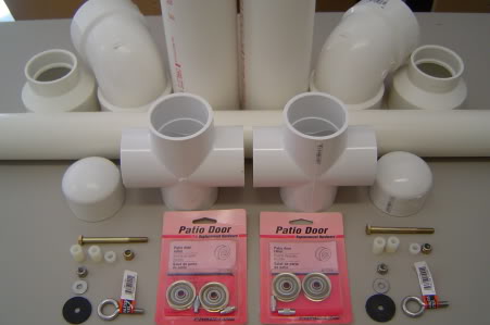
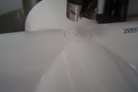
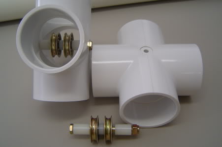
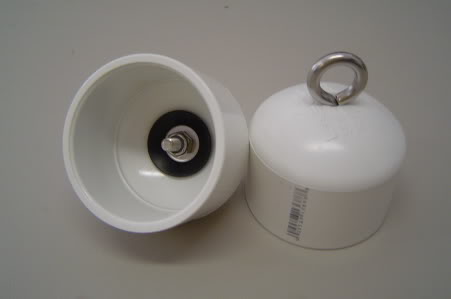
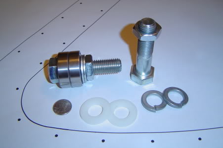
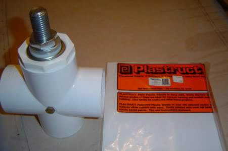
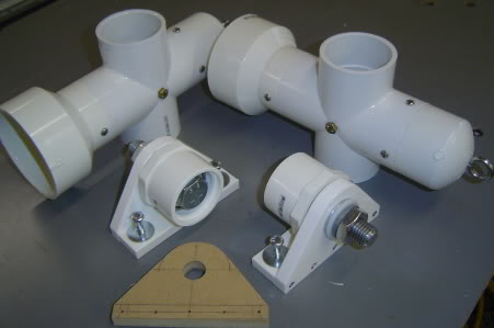
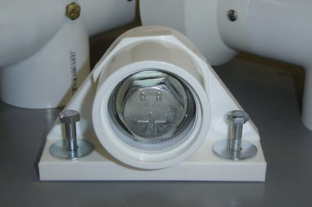
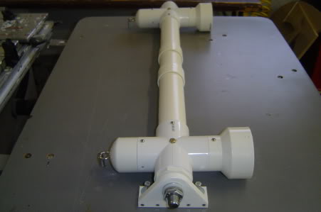
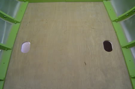
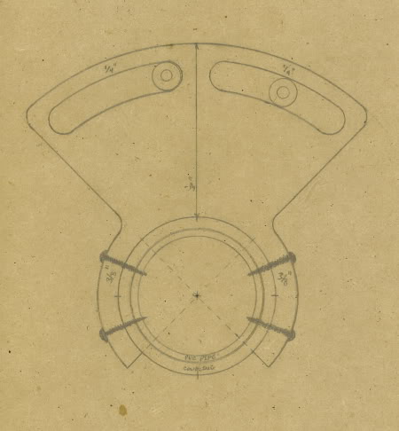
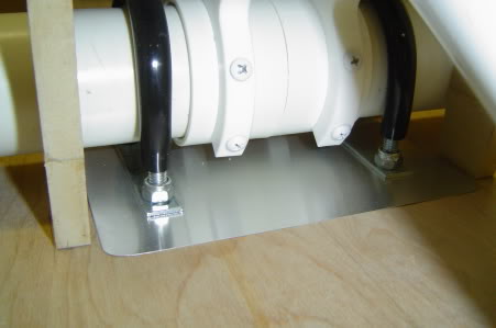
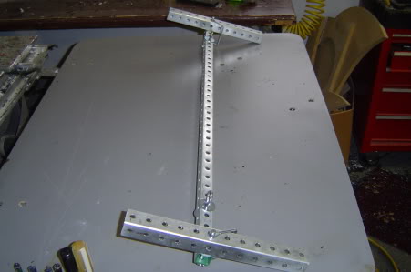
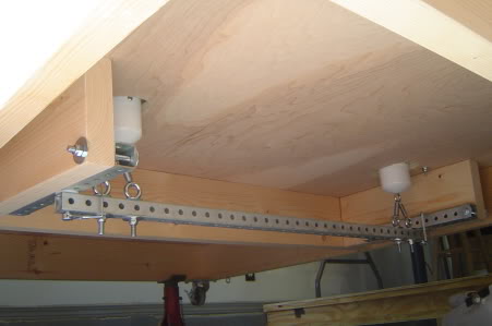
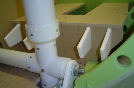
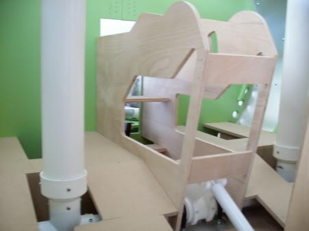
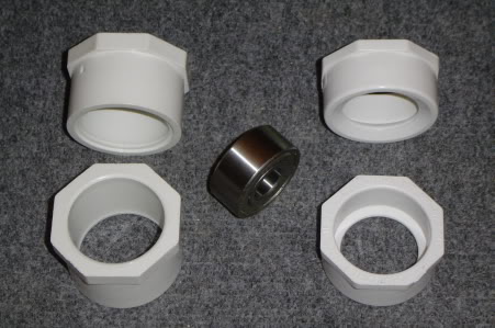
![]()
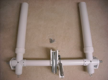
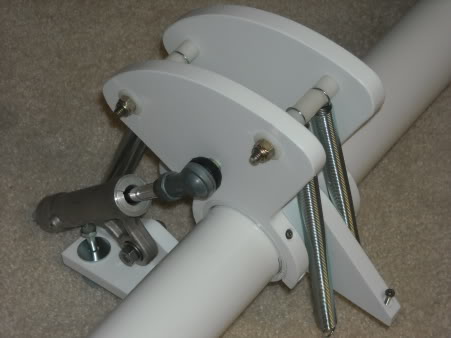
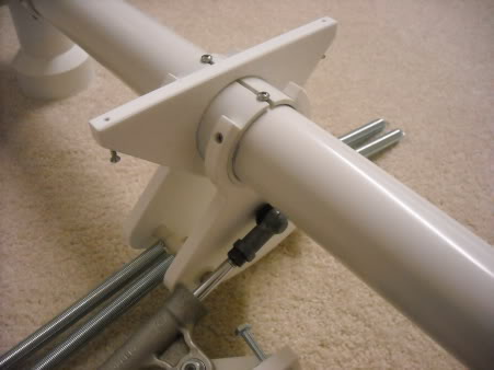
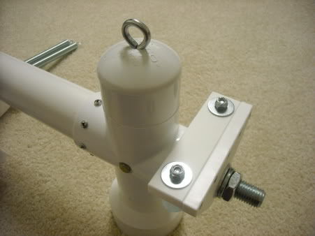
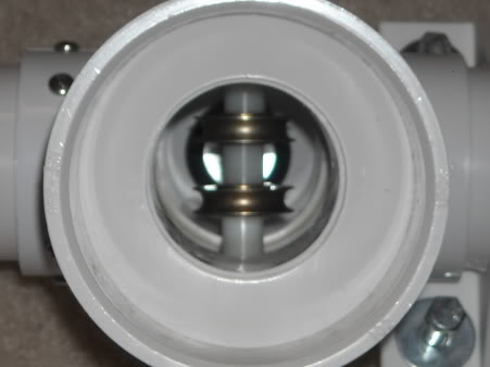
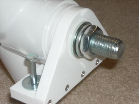
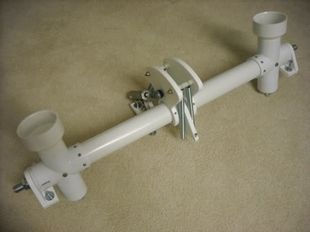
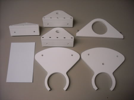
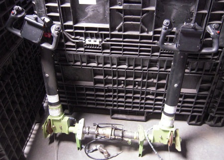
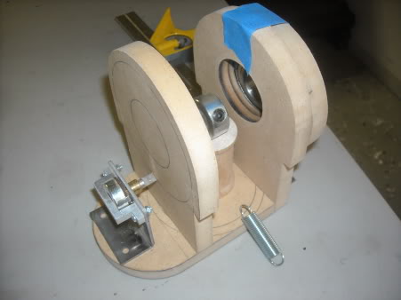
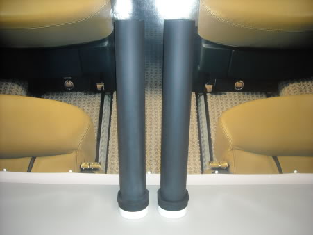
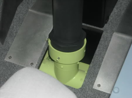
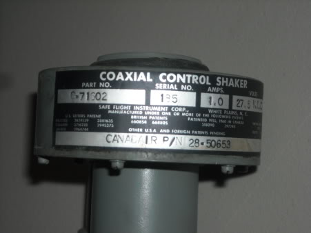
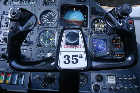
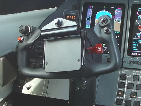
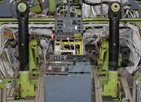
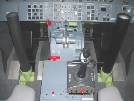
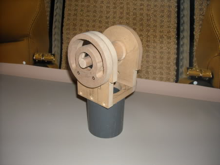
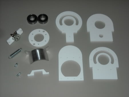
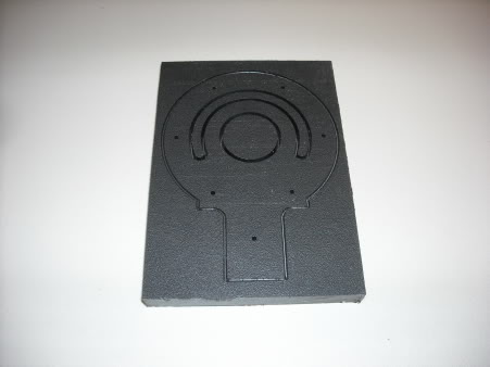
![]()
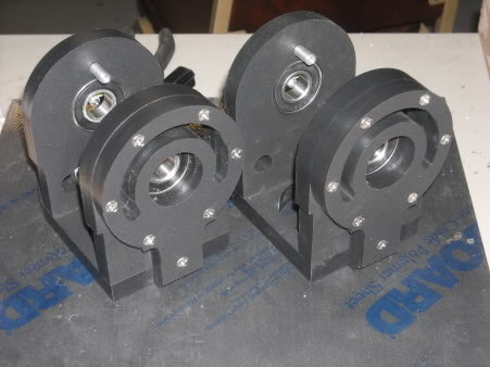
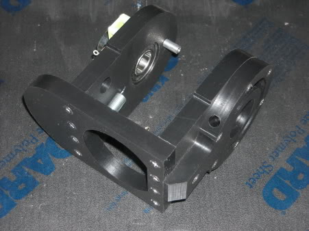
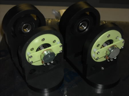
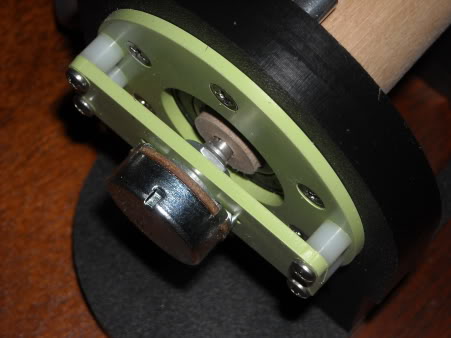
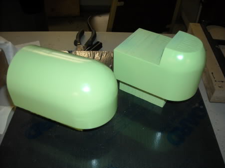
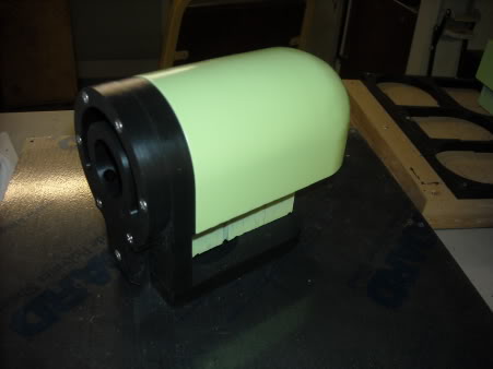
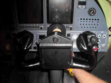
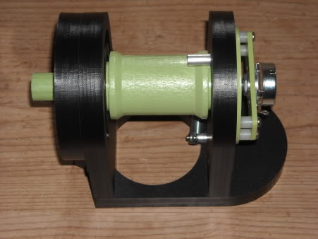
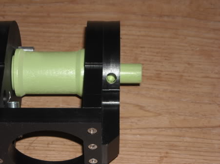
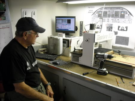
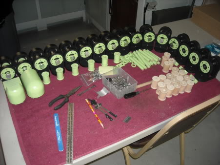
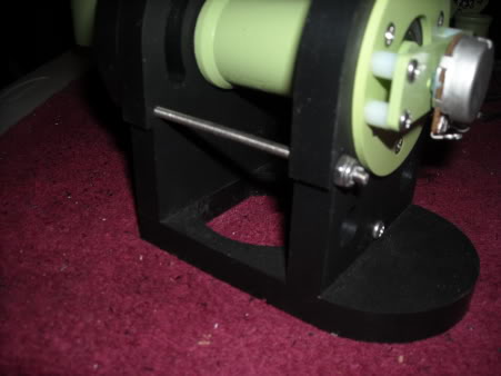
![]()
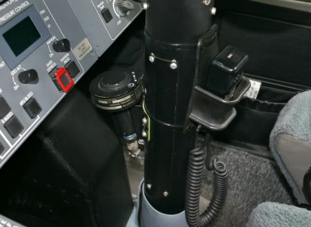
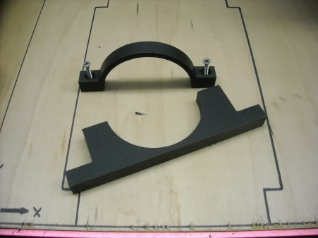
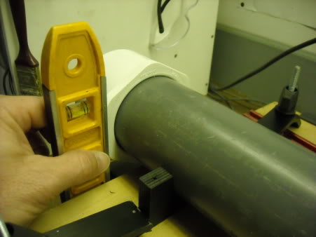
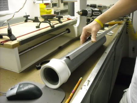
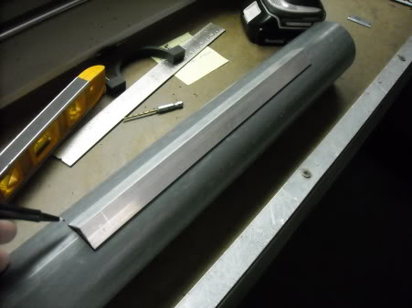
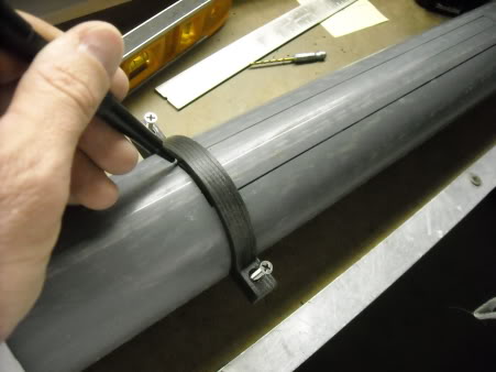
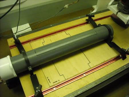
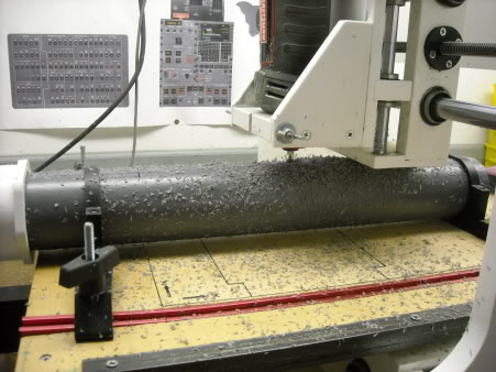
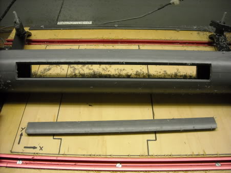
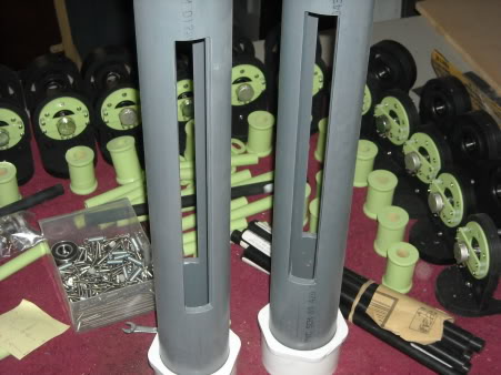
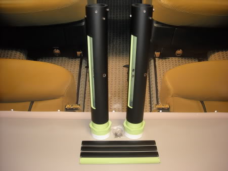
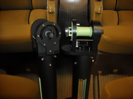
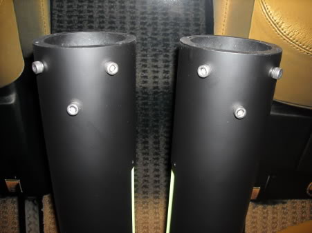
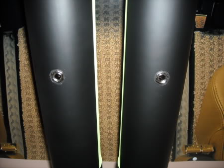
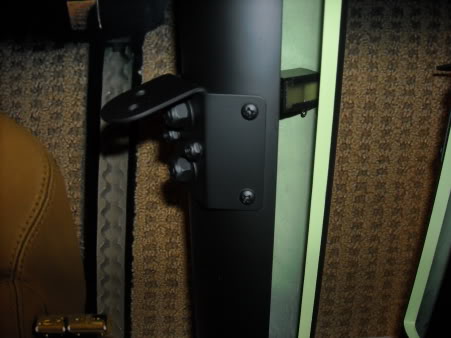
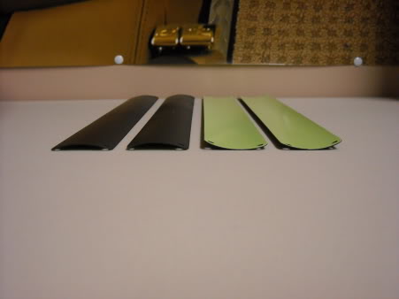
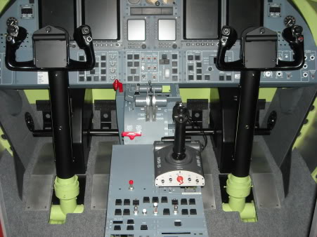
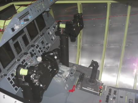
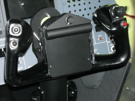
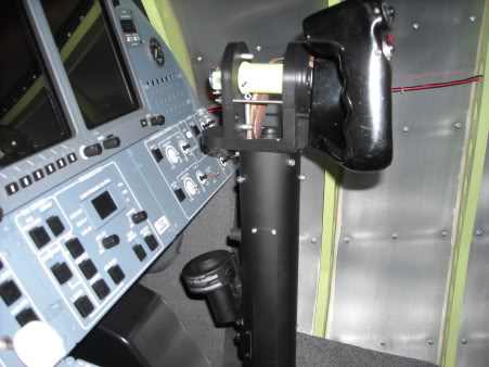
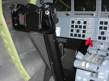
![]()
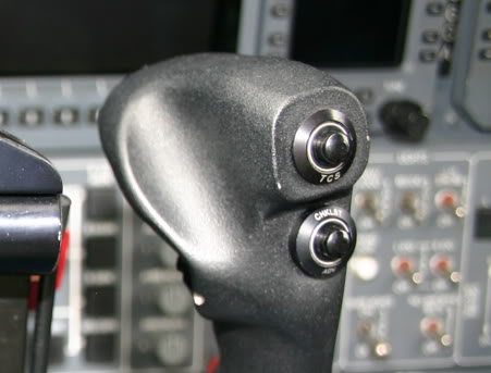
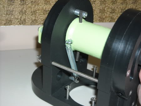
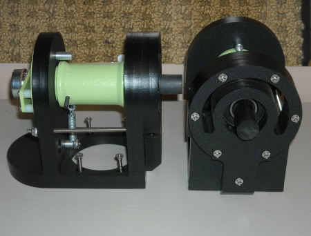
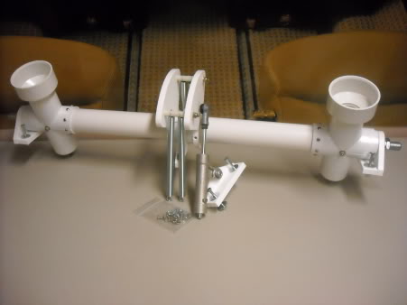
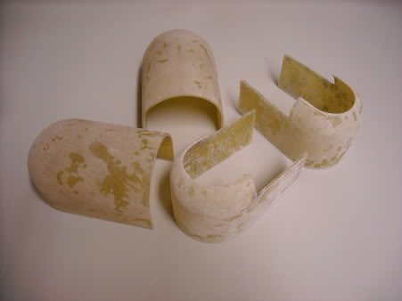
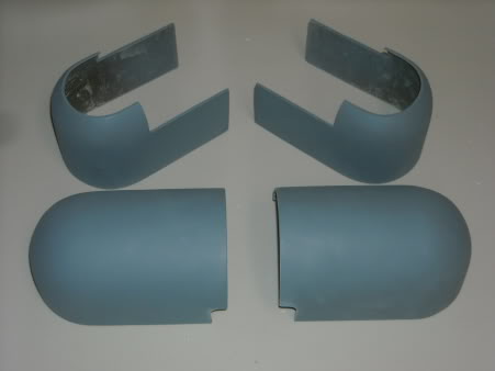
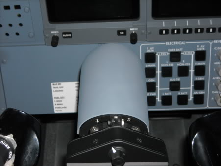
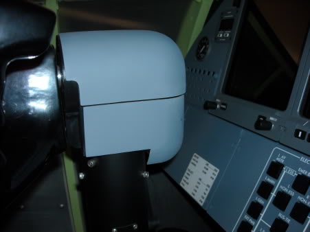
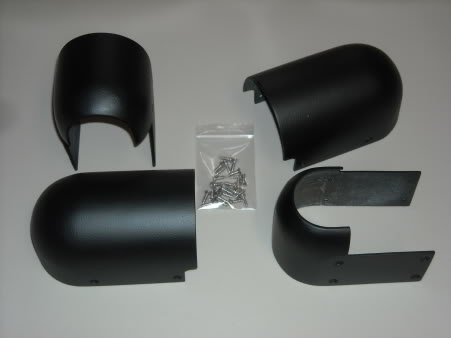
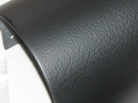
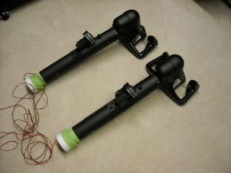
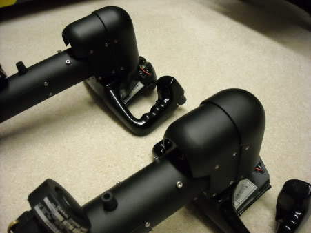
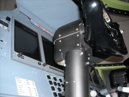
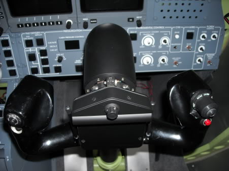
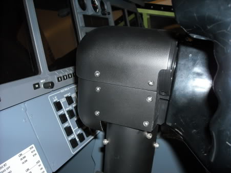
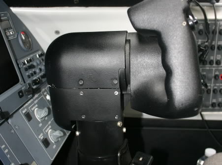
![]()
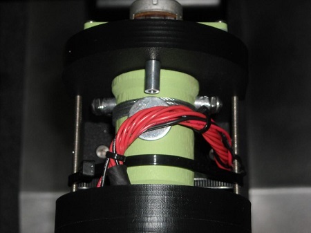
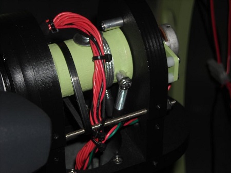
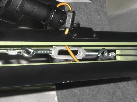
![]()
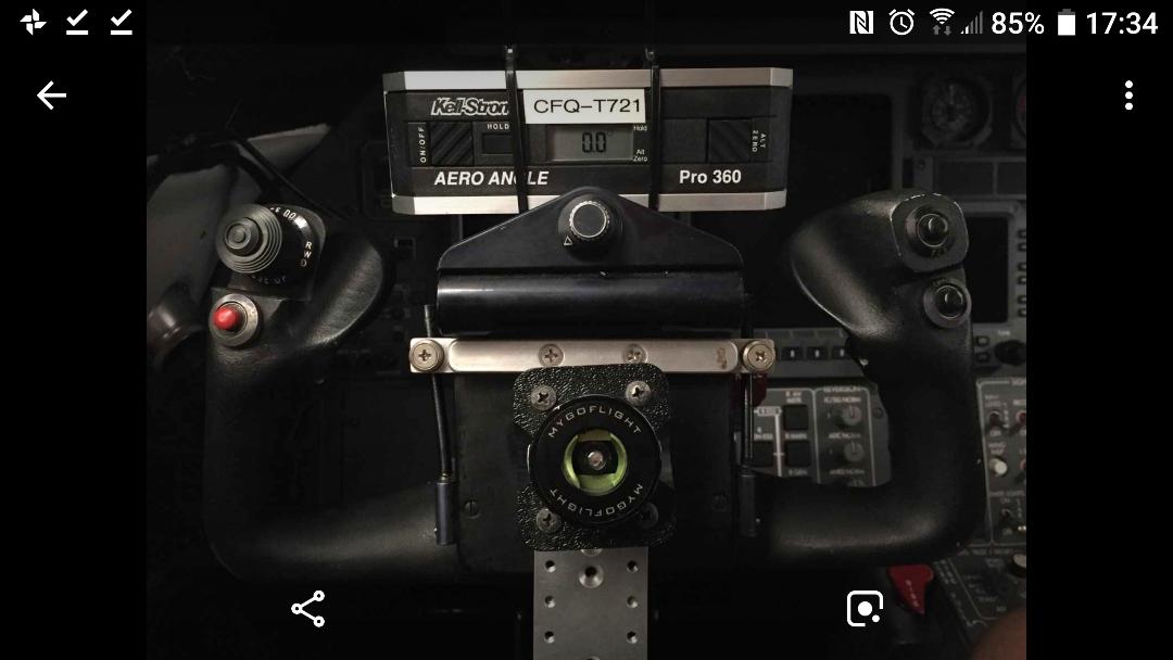
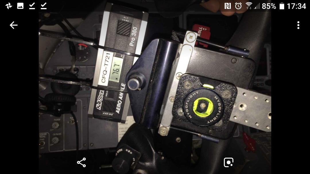
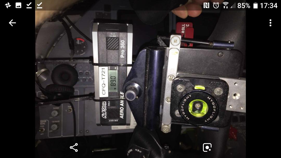
![]()
![]()
![]()
Forum NavigationColumn and Column Head Tutorial by Project45
![]() #1 · December 7, 2017, 7:24 am
#1 · December 7, 2017, 7:24 am![]() #2 · January 3, 2018, 8:17 am
#2 · January 3, 2018, 8:17 am![]() #3 · January 3, 2018, 8:28 am
#3 · January 3, 2018, 8:28 am![]() #4 · January 3, 2018, 8:59 am
#4 · January 3, 2018, 8:59 am![]() #5 · January 3, 2018, 9:32 am
#5 · January 3, 2018, 9:32 am![]() #6 · January 3, 2018, 10:06 am
#6 · January 3, 2018, 10:06 am![]() #7 · November 24, 2018, 3:17 pm
#7 · November 24, 2018, 3:17 pm![]() #8 · December 3, 2018, 10:45 am
#8 · December 3, 2018, 10:45 am![]() #9 · December 3, 2018, 10:59 am
#9 · December 3, 2018, 10:59 am![]() #10 · October 12, 2020, 5:52 pm
#10 · October 12, 2020, 5:52 pm
2017-10-10