


Lear 45-1001 Build History
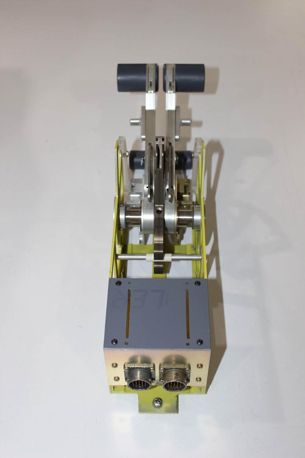
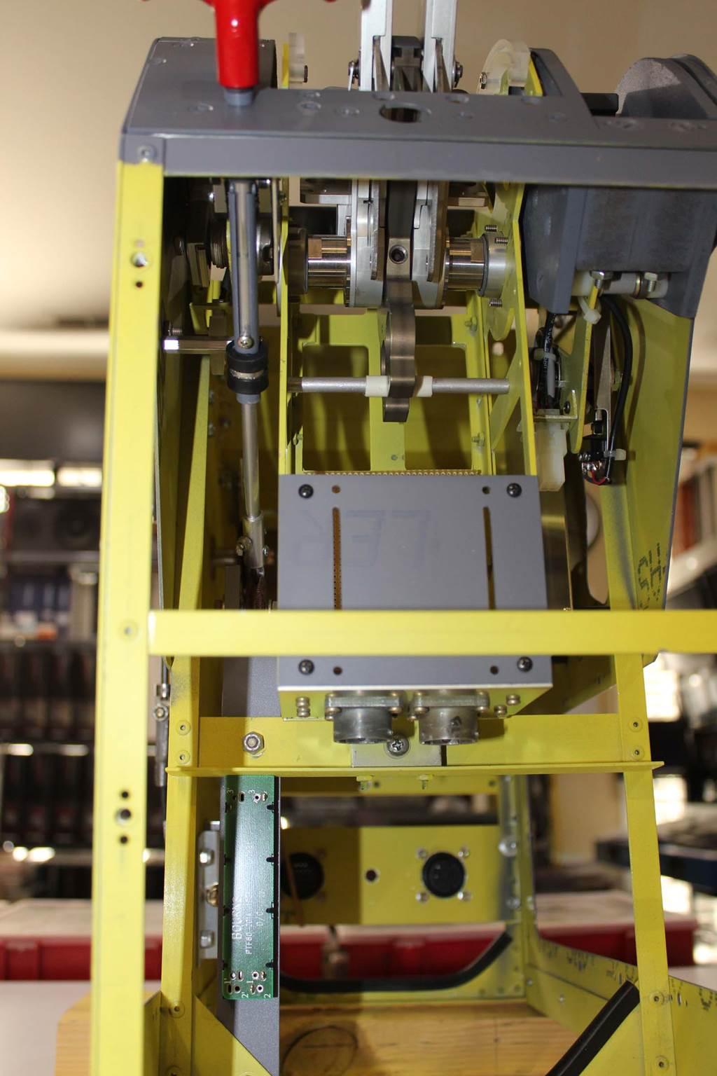
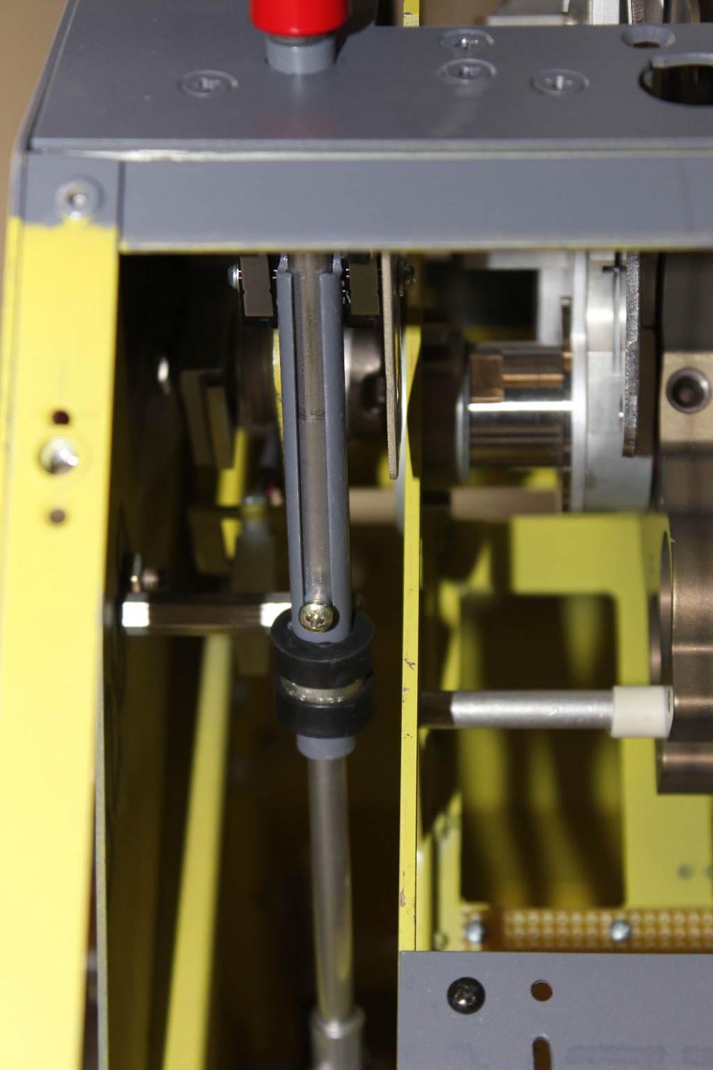
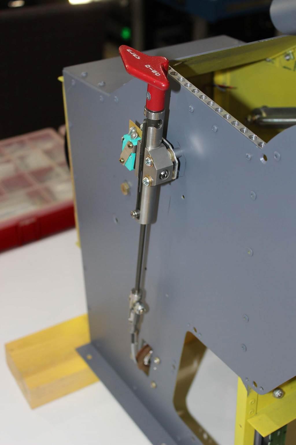
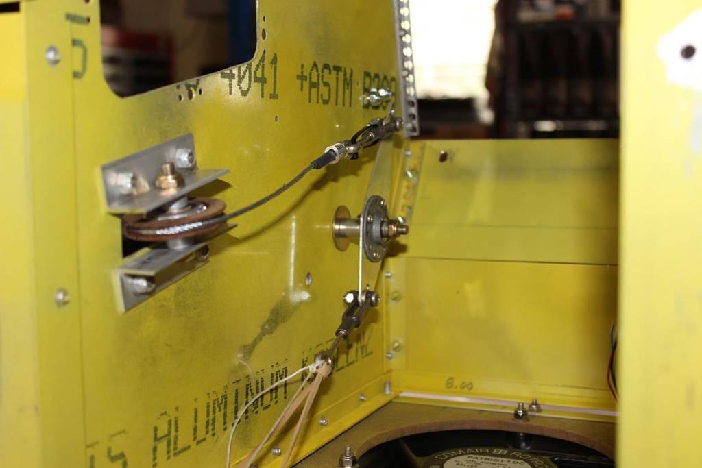
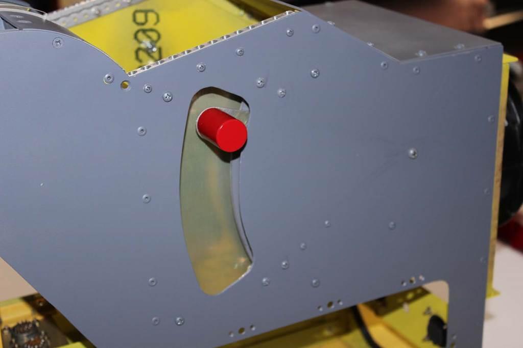
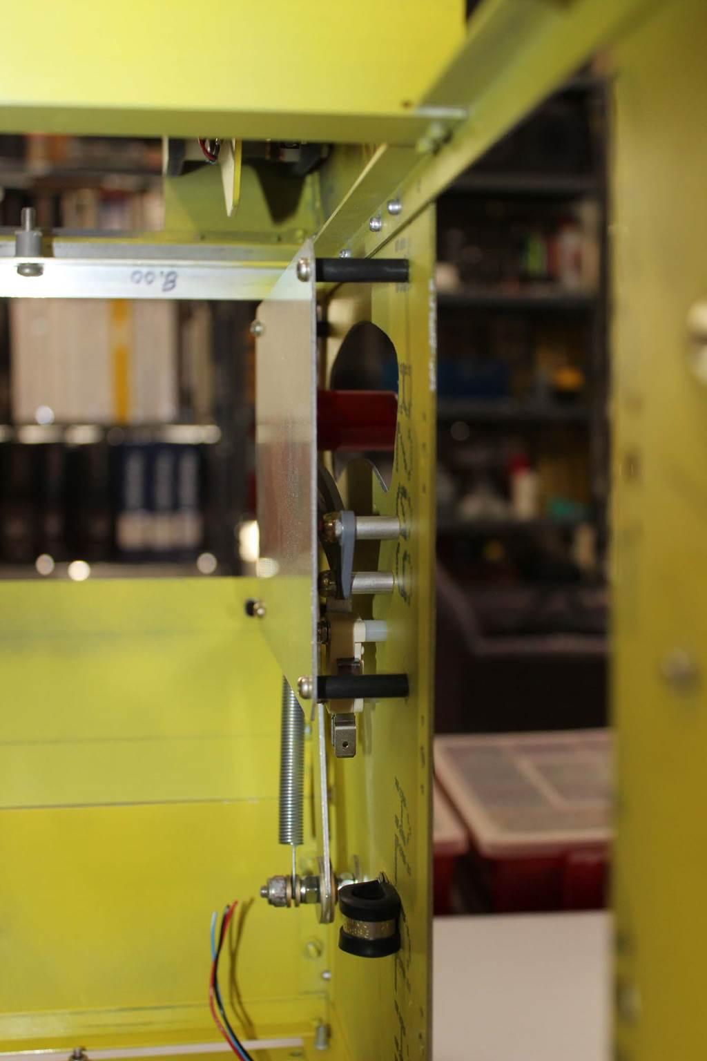
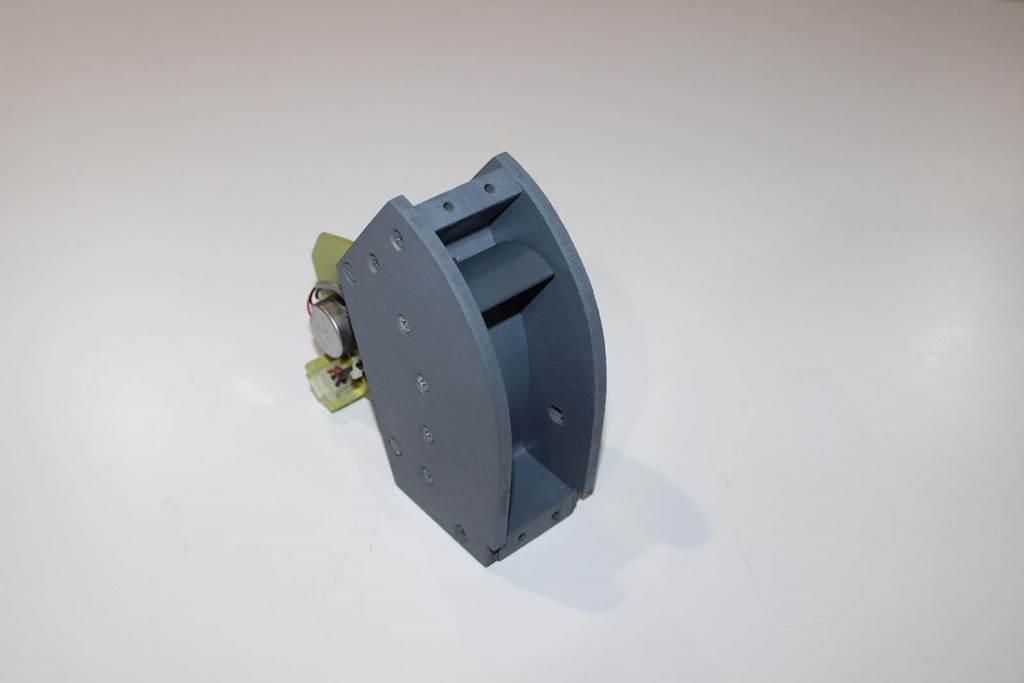
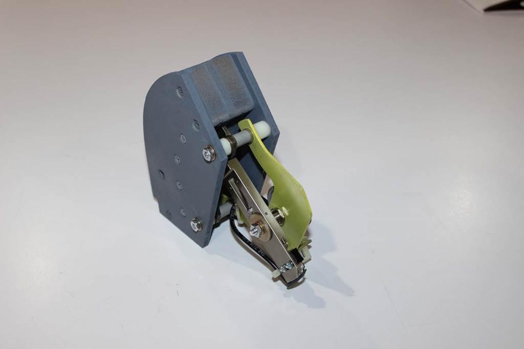
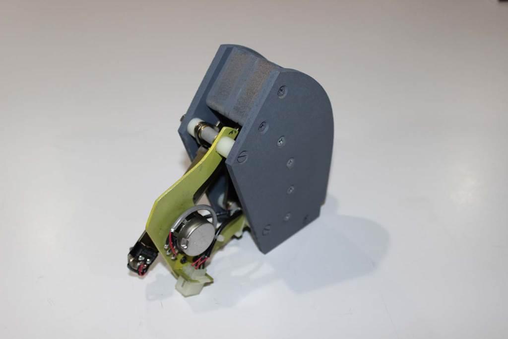
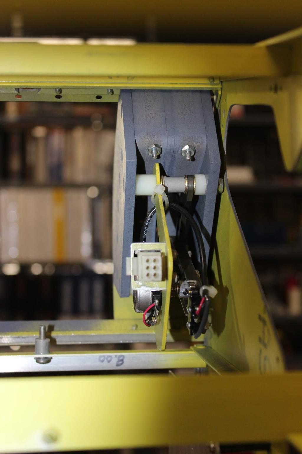
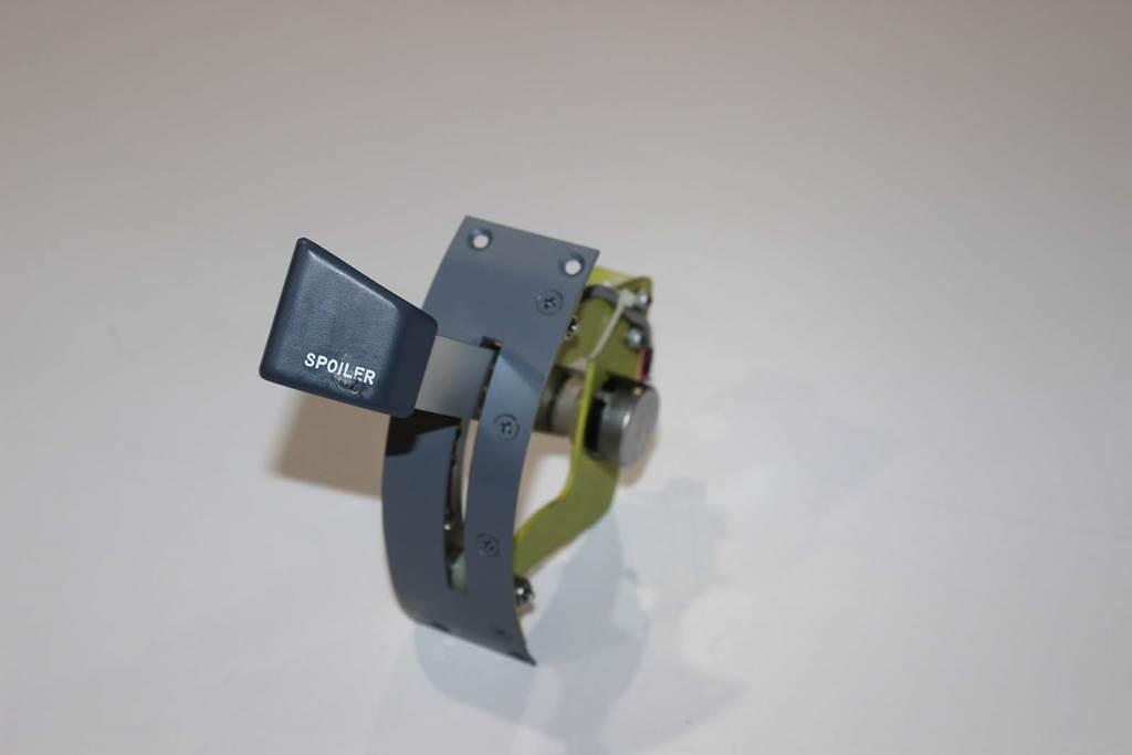
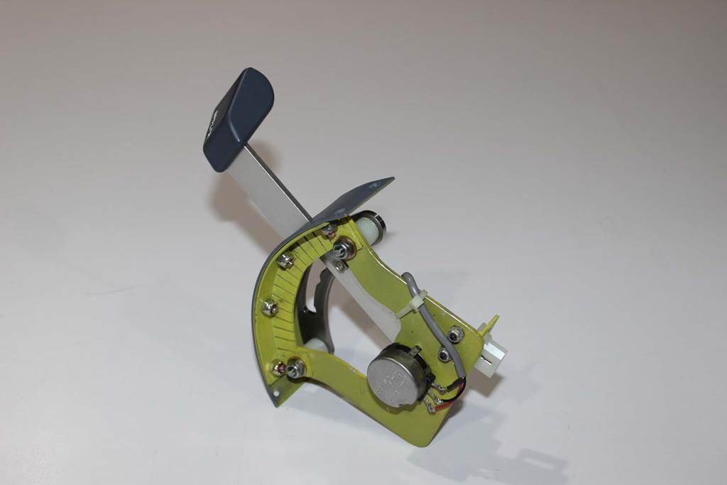
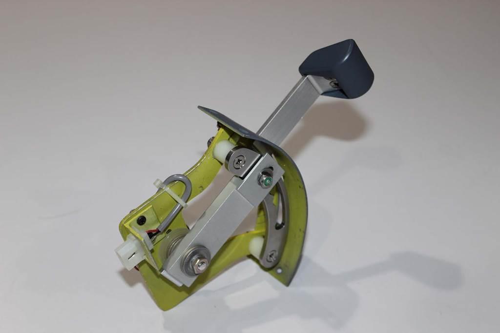
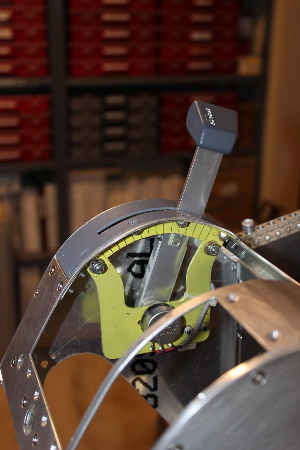
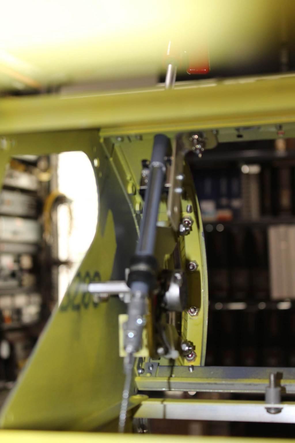
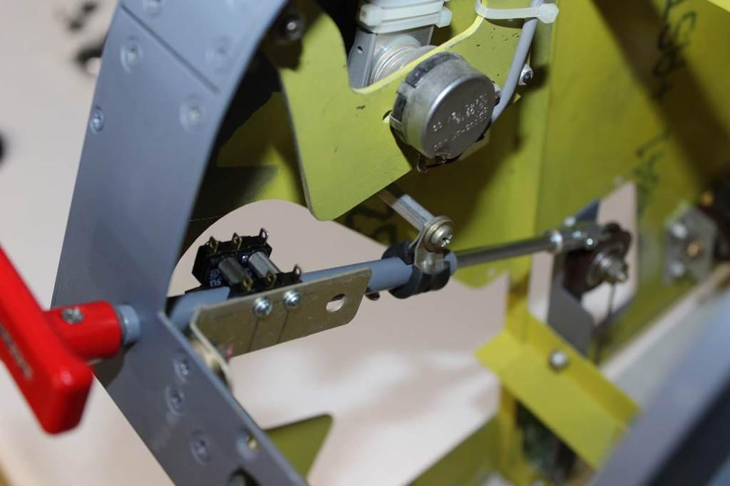
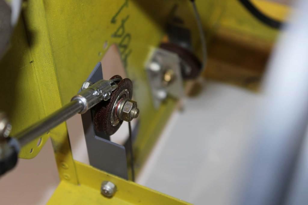
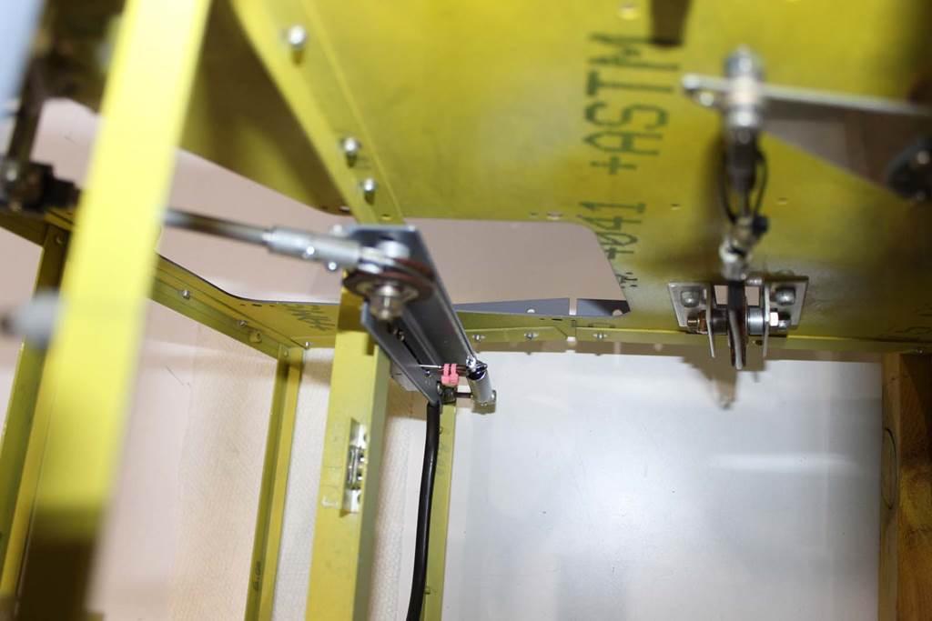
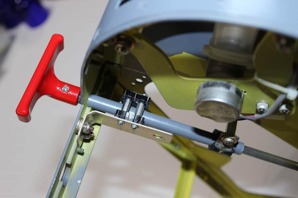
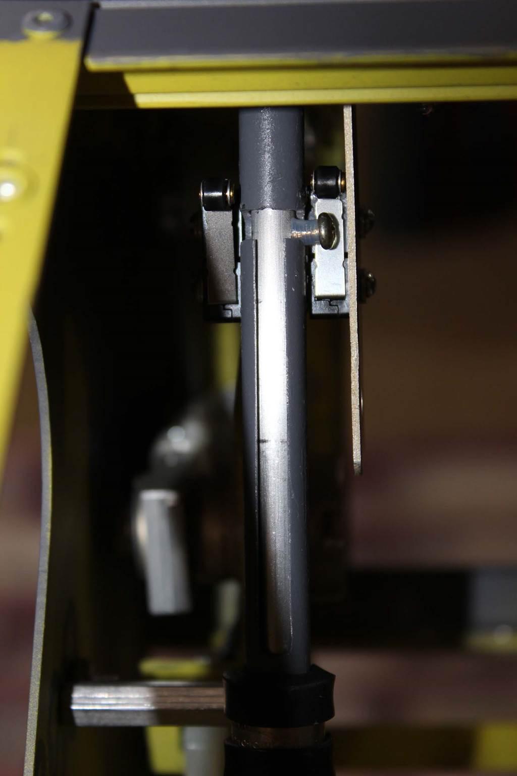
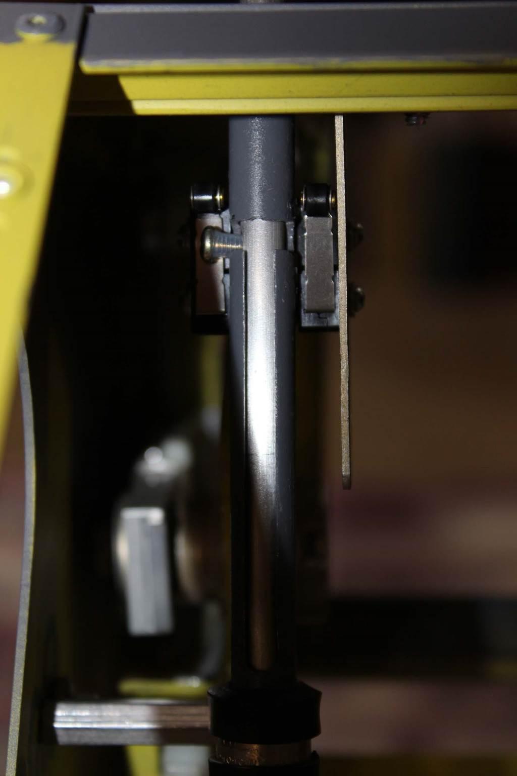
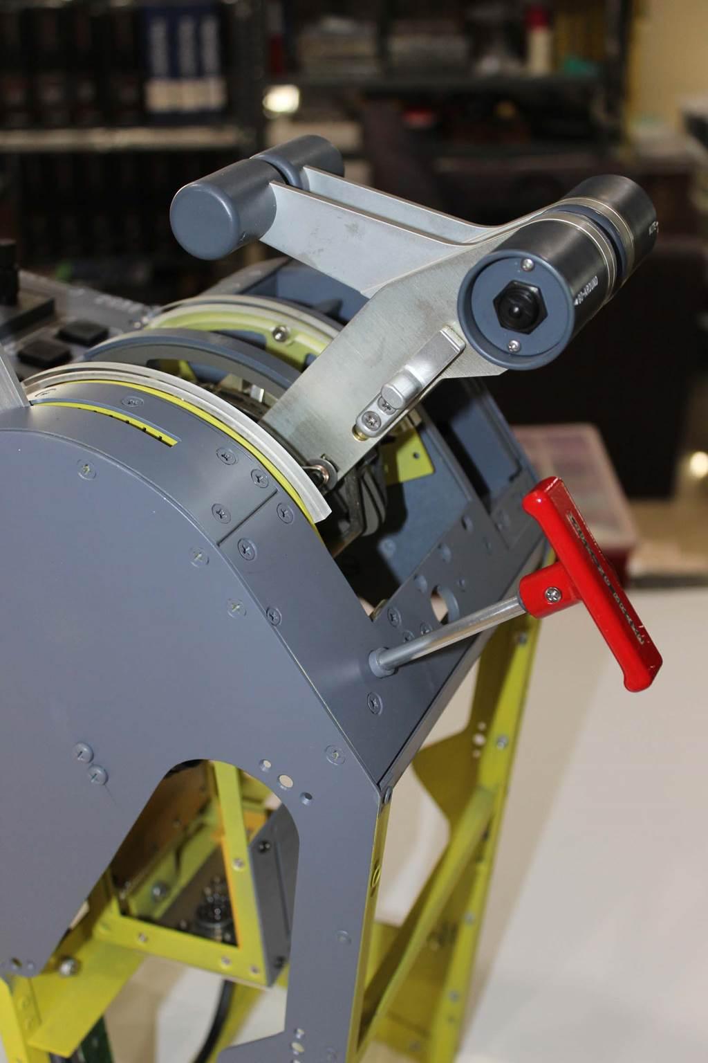
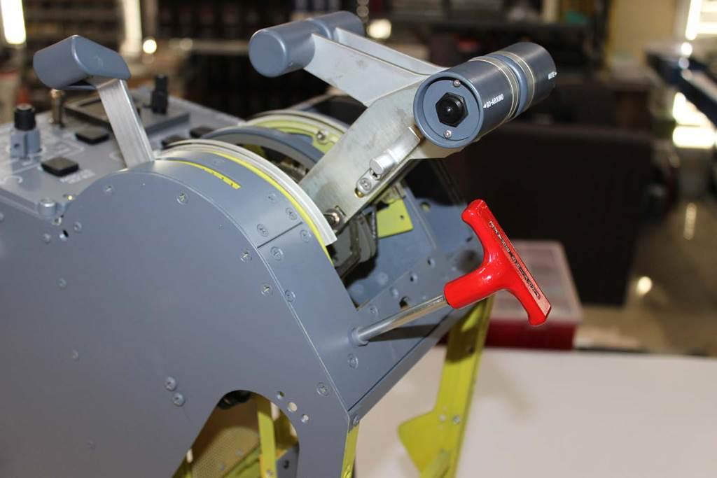
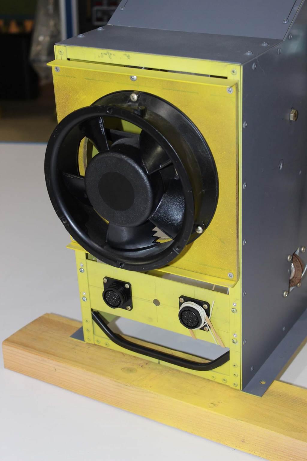
ATA-27 The L45-1001 introduction contains useful background information on this build. If somehow you have arrived at this place and have not read the L45-1001 introduction you will find it HERE NOTE: Right click on the images below and select "Open Image in New Tab" to increase size. (This feature does not work with some browsers.) Please refer to the comments BELOW each photo. Secondary Flight Controls Secondary flight controls include flaps, spoilers, landing gear freefall, elevator disconnect and emergency / park brake. The cockpit controls for all of these are located in the forward pedestal. The engine controls (the thrust lever assembly, or TLA) are also located in the forward pedestal. Details on the TLA are in a separate posting for the engine controls. The TLA is shown here to illustrate how the various assemblies are arranged in the pedestal. The forward pedestal was constructed from the OEM factory structural drawings because many of the controls used on L45-1001 are real Learjet parts. The scale had to be correct to use those parts. The nut plates for the cover screws are not installed in this photo. (I’m out of the 3/32” flat head countersink rivets for the nut plates at the moment, but more are on order.) The thrust lever assembly (TLA) is an entirely self-contained unit. It mounts to the pedestal structural members and is held in place by two fasteners, one at the top and one at the bottom. The TLA can be removed from the airplane in about ten minutes without having to disturb either the forward or aft pedestals. All engine thrust lever controls (reverser switches, thrust lever angle sensors, detent switches, etc) are wired through the two multi pin connectors on the bottom of the TLA. Pedestal Interior Components This turned out better than expected. There’s a lot of stuff inside the TLA/pedestal and it all has to fit without conflict. The most recent part I made was the EMER/PARK brake mechanism. Since it was the last part to arrive at the party it HAD TO BE no larger than the real part to fit. It took me a while to conjure up this solution, but it works well and fits in the space allocated for the brake control mechanism. This version of the EMER/PARK mechanism is similar to the real part but modified to fit in the lower part of the pedestal. (The real part is straight and does not loop the cable over a pulley as shown here. The real cable goes down into the innards of the airplane and travels aft to a hydraulic valve. Since there is no “aft” or wing box in L45-1001 the brake sensor is located as shown.) The bracket that holds the micro switches on the brake mechanism clears the TLA by about 1/16” (!). Look at the micro switches at the top in the photo, then follow the shaft guide straight down. You can see the tail of the micro switch bracket right next to the side of the TLA. Elevator Disconnect Control This is the ELEV DISC handle assembly. This is the real Lear 45 part and is used in the same manner as the real airplane. The actuating cable travels inside the pedestal and below the floor line to the forward elevator disconnect clutch located on the elevator torque tube (crossover tube). The ELEV DISC cable is routed inside the pedestal. In the real airplane it continues downward and aft through a series of pulleys and then goes to the forward elevator disconnect clutch on the crossover tube. The swing arm you see in this photo would be located in a space below the floor line and attached to structural elements that do not exist in L45-1001. I put the swing arm inside the pedestal because there was space available for it. The swing arm is an interesting piece of the system. The length of the ELEV DISC HANDLE travel does not match the length of the CLUTCH pivot travel on the crossover tube. An offset swing arm matches up the travel of both ends at different rates because the pivot center is offset. Should you ever decide to include real elevator disconnect in your sim you’ll need something like this but you may not realize it until you’ve made a stack of scrap parts. So this is your heads up. Plan for this. (Do not ask me how I know this.......ahem.) Gear FREE FALL Lever The gear FREE FALL lever on the right side of the pedestal is used for emergency extension of the landing gear. In the real airplane this lever pulls a series of cables that manually un-latch the landing gear up lock mechanisms. When un-latched, gravity pulls the landing gear into the extended position (DOWN). Since we don't have physical landing gear in our sims this lever operates a switch to signal the software that the gear is commanded down. It may not actually go down and lock, but it's commanded down. This, of course, occasionally happens in real life with real airplanes. That's when you earn your pay as a Learjet Captain. Ron’s gear FREE FALL lever mechanism. The real part is made as a single sub-assembly with a plate inboard of the handle to protect it. I added the plate in the photo to Ron’s parts. FLAPS Selection Mechanism The FLAPS selection mechanism as installed in the pedestal. These are real parts with some Ron parts and some DonnyRay parts. The connector makes it possible to remove the entire flaps “bucket” without disturbing anything else in the pedestal. In the real airplane these sub-assemblies are connectorized for ease of maintenance. SPOILER Control Mechanism You really can’t see the SPOILER control mechanism once other components are installed because other things are in front of it. It’s real parts mounted on a DonnyRay bracket and connectorized for easy removal. Please excuse the poor quality photo. I couldn’t find any spot from which to get a better photo of the spoiler control mechanism once it was installed in the pedestal with all the other innards. EMER/PARK Brake Mechanism EMER/PARK brake mechanism guide tube, anchor and micro switches. The actuator tube attaches to a piece of control cable just above the pulley. A “coupler” on the end of the actuator shaft makes it easy to disconnect the cable from the handle shaft without having to re-thread the cable every time. Removing one screw detaches the cable from the handle rod, leaving the cable still attached to the coupler. This turned out to be VERY handy. I bet I took that thing apart a hundred times while working on getting all the travel lengths and micro switch positioning right. The cable goes over the pulley and straight down to a spring. The top of the spring is attached to the wiper of a linear pot. As the handle is pulled, the cable moves and carries the pot wiper with it. Reading this pot is how I get the braking signal to be applied to the braking system. It is proportional to how FAR the pilot has pulled the handle away from the stowed position. The “more you pull” the “more brakes you get”. (In the real airplane the cable pulls directly on a hydraulic valve actuator lever. The more you pull, the more hydraulic pressure is applied to the brakes and "the more brakes you get".) The micro switches sense when the brake handle has been ROTATED at the full extension of travel. ROTATED is the PARK brake position. PULLED is the EMER brake position. You do not want the airplane to think the PARK brake is set if you are using the handle to apply emergency braking. So you must pull the handle all the way OUT to the stop and THEN rotate it 90 degrees to engage either micro switch. The micro switch informs the airplane that the PARK brake is applied. I don’t know why Learjet made it possible to rotate the handle either way, but they did, and that required me to provide two micro switches. One for each direction of rotation. This photo also gives you a good view of that bracket that clears the TLA by only 1/16”. Handle extended and turned LEFT 90 degrees. The actuator pin catches the micro switch on the RIGHT. The pin is just a common screw. The clear sleeving on the screw threads is Teflon. It makes that screw slide smoothly along the slot. I suppose I could buy a legitimate “pin” from McMaster-Carr or MSC but this screw seems to work just fine. Handle turned RIGHT 90 degrees and the pin catches the LEFT micro switch. These switches are essentially wired in parallel. It doesn’t matter which switch operates. All that matters is that we tell the airplane that the park brake is SET. The real part uses a different method of actuating the micro switch and consequently only needs a single micro switch. I could not fabricate a real part replica without welding and special tooling but this design works and was within my ability to fabricate. Pulled and rotated LEFT. The handle travel is 2-3/8”. It is 2-3/8” because that is the travel of the linear pot down on the cable. Ron and I believe the real airplane handle travel is something like 2.75-3.25”. Ron had someone measure it but I forget what that dimension was. It really doesn’t matter on L45-1001 because there isn’t room for a longer slide pot in the pedestal. So my handle travel is 2-3/8”, but that is not consistent with the real airplane. Pulled and rotated RIGHT. The sharp-eye’d amongst you will observe that the legend on the handle isn’t correct for a Lear 45. That’s because the handle in the photo is from a Lear 35A. Shhhhh.........don’t tell anybody. All those various switches and pots in the pedestal get wired to these two multi pin connectors. This makes it possible to disconnect these two connectors, the connectors on the TLA, and the ELEV DISC mechanical cable, and remove the forward pedestal from the airplane completely intact. The SYS TEST panel and the CDR have their own wiring cables. They are connectorized on the back side of the SYS TEST panel, but that wiring does not pass through these connectors. HOME: This link goes to the L45-1001 build history introduction. Links to other L45-1001 posts are found at the END of the introduction HERE Lear 45-1001 Build History
ATA-27 The L45-1001 introduction contains useful background information on this build. If somehow you have arrived at this place and have not read the L45-1001 introduction you will find it HERE NOTE: Right click on the images below and select "Open Image in New Tab" to increase size. (This feature does not work with some browsers.) Please refer to the comments BELOW each photo. Secondary Flight Controls Secondary flight controls include flaps, spoilers, landing gear freefall, elevator disconnect and emergency / park brake. The cockpit controls for all of these are located in the forward pedestal. The engine controls (the thrust lever assembly, or TLA) are also located in the forward pedestal. Details on the TLA are in a separate posting for the engine controls. The TLA is shown here to illustrate how the various assemblies are arranged in the pedestal. The forward pedestal was constructed from the OEM factory structural drawings because many of the controls used on L45-1001 are real Learjet parts. The scale had to be correct to use those parts. The nut plates for the cover screws are not installed in this photo. (I’m out of the 3/32” flat head countersink rivets for the nut plates at the moment, but more are on order.) The thrust lever assembly (TLA) is an entirely self-contained unit. It mounts to the pedestal structural members and is held in place by two fasteners, one at the top and one at the bottom. The TLA can be removed from the airplane in about ten minutes without having to disturb either the forward or aft pedestals. All engine thrust lever controls (reverser switches, thrust lever angle sensors, detent switches, etc) are wired through the two multi pin connectors on the bottom of the TLA. Pedestal Interior Components This turned out better than expected. There’s a lot of stuff inside the TLA/pedestal and it all has to fit without conflict. The most recent part I made was the EMER/PARK brake mechanism. Since it was the last part to arrive at the party it HAD TO BE no larger than the real part to fit. It took me a while to conjure up this solution, but it works well and fits in the space allocated for the brake control mechanism. This version of the EMER/PARK mechanism is similar to the real part but modified to fit in the lower part of the pedestal. (The real part is straight and does not loop the cable over a pulley as shown here. The real cable goes down into the innards of the airplane and travels aft to a hydraulic valve. Since there is no “aft” or wing box in L45-1001 the brake sensor is located as shown.) The bracket that holds the micro switches on the brake mechanism clears the TLA by about 1/16” (!). Look at the micro switches at the top in the photo, then follow the shaft guide straight down. You can see the tail of the micro switch bracket right next to the side of the TLA. Elevator Disconnect Control This is the ELEV DISC handle assembly. This is the real Lear 45 part and is used in the same manner as the real airplane. The actuating cable travels inside the pedestal and below the floor line to the forward elevator disconnect clutch located on the elevator torque tube (crossover tube). The ELEV DISC cable is routed inside the pedestal. In the real airplane it continues downward and aft through a series of pulleys and then goes to the forward elevator disconnect clutch on the crossover tube. The swing arm you see in this photo would be located in a space below the floor line and attached to structural elements that do not exist in L45-1001. I put the swing arm inside the pedestal because there was space available for it. The swing arm is an interesting piece of the system. The length of the ELEV DISC HANDLE travel does not match the length of the CLUTCH pivot travel on the crossover tube. An offset swing arm matches up the travel of both ends at different rates because the pivot center is offset. Should you ever decide to include real elevator disconnect in your sim you’ll need something like this but you may not realize it until you’ve made a stack of scrap parts. So this is your heads up. Plan for this. (Do not ask me how I know this.......ahem.) Gear FREE FALL Lever The gear FREE FALL lever on the right side of the pedestal is used for emergency extension of the landing gear. In the real airplane this lever pulls a series of cables that manually un-latch the landing gear up lock mechanisms. When un-latched, gravity pulls the landing gear into the extended position (DOWN). Since we don't have physical landing gear in our sims this lever operates a switch to signal the software that the gear is commanded down. It may not actually go down and lock, but it's commanded down. This, of course, occasionally happens in real life with real airplanes. That's when you earn your pay as a Learjet Captain. Ron’s gear FREE FALL lever mechanism. The real part is made as a single sub-assembly with a plate inboard of the handle to protect it. I added the plate in the photo to Ron’s parts. FLAPS Selection Mechanism The FLAPS selection mechanism as installed in the pedestal. These are real parts with some Ron parts and some DonnyRay parts. The connector makes it possible to remove the entire flaps “bucket” without disturbing anything else in the pedestal. In the real airplane these sub-assemblies are connectorized for ease of maintenance. SPOILER Control Mechanism You really can’t see the SPOILER control mechanism once other components are installed because other things are in front of it. It’s real parts mounted on a DonnyRay bracket and connectorized for easy removal. Please excuse the poor quality photo. I couldn’t find any spot from which to get a better photo of the spoiler control mechanism once it was installed in the pedestal with all the other innards. EMER/PARK Brake Mechanism EMER/PARK brake mechanism guide tube, anchor and micro switches. The actuator tube attaches to a piece of control cable just above the pulley. A “coupler” on the end of the actuator shaft makes it easy to disconnect the cable from the handle shaft without having to re-thread the cable every time. Removing one screw detaches the cable from the handle rod, leaving the cable still attached to the coupler. This turned out to be VERY handy. I bet I took that thing apart a hundred times while working on getting all the travel lengths and micro switch positioning right. The cable goes over the pulley and straight down to a spring. The top of the spring is attached to the wiper of a linear pot. As the handle is pulled, the cable moves and carries the pot wiper with it. Reading this pot is how I get the braking signal to be applied to the braking system. It is proportional to how FAR the pilot has pulled the handle away from the stowed position. The “more you pull” the “more brakes you get”. (In the real airplane the cable pulls directly on a hydraulic valve actuator lever. The more you pull, the more hydraulic pressure is applied to the brakes and "the more brakes you get".) The micro switches sense when the brake handle has been ROTATED at the full extension of travel. ROTATED is the PARK brake position. PULLED is the EMER brake position. You do not want the airplane to think the PARK brake is set if you are using the handle to apply emergency braking. So you must pull the handle all the way OUT to the stop and THEN rotate it 90 degrees to engage either micro switch. The micro switch informs the airplane that the PARK brake is applied. I don’t know why Learjet made it possible to rotate the handle either way, but they did, and that required me to provide two micro switches. One for each direction of rotation. This photo also gives you a good view of that bracket that clears the TLA by only 1/16”. Handle extended and turned LEFT 90 degrees. The actuator pin catches the micro switch on the RIGHT. The pin is just a common screw. The clear sleeving on the screw threads is Teflon. It makes that screw slide smoothly along the slot. I suppose I could buy a legitimate “pin” from McMaster-Carr or MSC but this screw seems to work just fine. Handle turned RIGHT 90 degrees and the pin catches the LEFT micro switch. These switches are essentially wired in parallel. It doesn’t matter which switch operates. All that matters is that we tell the airplane that the park brake is SET. The real part uses a different method of actuating the micro switch and consequently only needs a single micro switch. I could not fabricate a real part replica without welding and special tooling but this design works and was within my ability to fabricate. Pulled and rotated LEFT. The handle travel is 2-3/8”. It is 2-3/8” because that is the travel of the linear pot down on the cable. Ron and I believe the real airplane handle travel is something like 2.75-3.25”. Ron had someone measure it but I forget what that dimension was. It really doesn’t matter on L45-1001 because there isn’t room for a longer slide pot in the pedestal. So my handle travel is 2-3/8”, but that is not consistent with the real airplane. Pulled and rotated RIGHT. The sharp-eye’d amongst you will observe that the legend on the handle isn’t correct for a Lear 45. That’s because the handle in the photo is from a Lear 35A. Shhhhh.........don’t tell anybody. All those various switches and pots in the pedestal get wired to these two multi pin connectors. This makes it possible to disconnect these two connectors, the connectors on the TLA, and the ELEV DISC mechanical cable, and remove the forward pedestal from the airplane completely intact. The SYS TEST panel and the CDR have their own wiring cables. They are connectorized on the back side of the SYS TEST panel, but that wiring does not pass through these connectors. HOME: This link goes to the L45-1001 build history introduction. Links to other L45-1001 posts are found at the END of the introduction HEREATA 27 Secondary Flight Controls
![]()
Secondary Flight Controls
Rev June 2026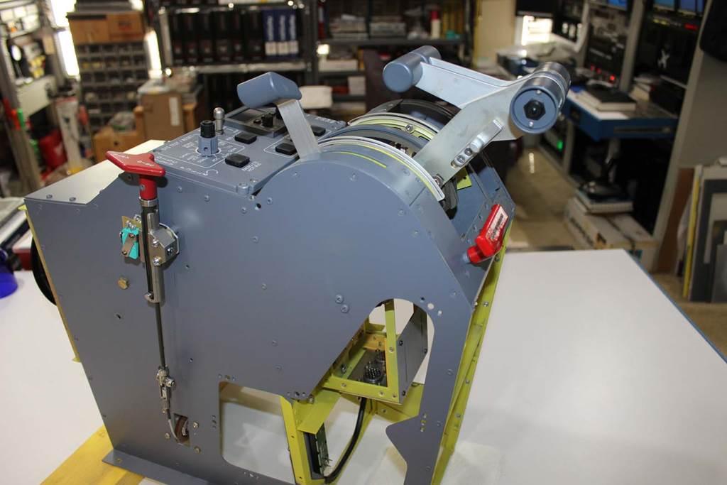
Secondary Flight Controls
Rev June 2026
2017-10-10