


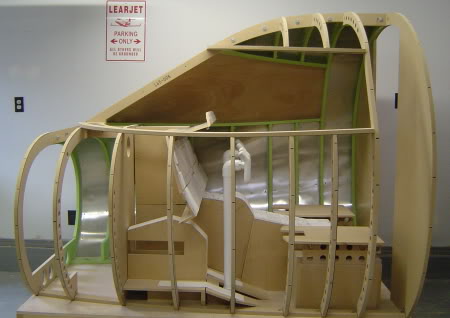
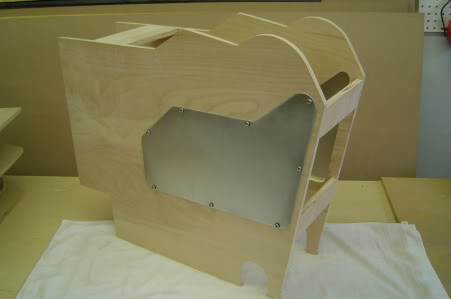
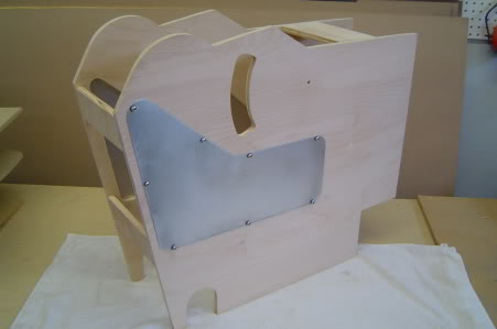
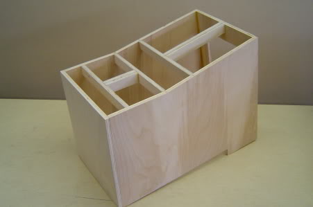
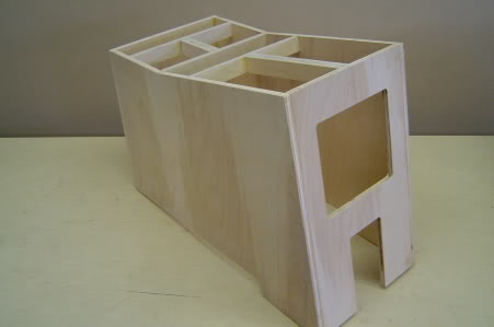
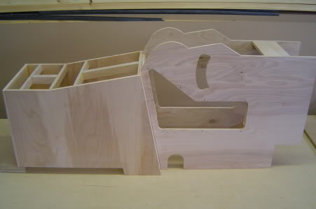
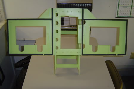
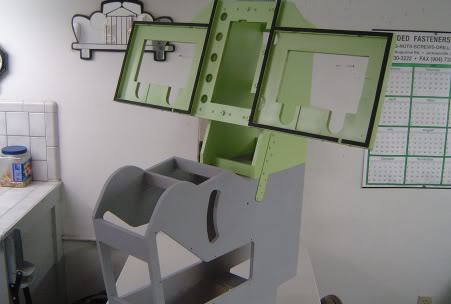
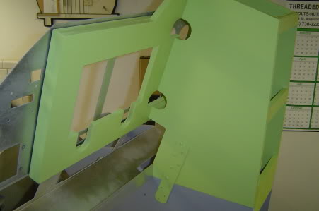
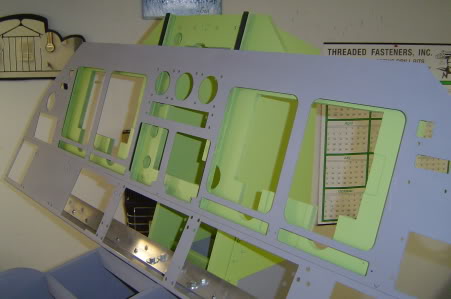
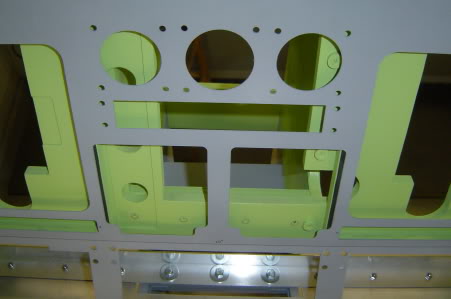
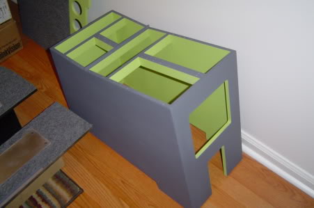
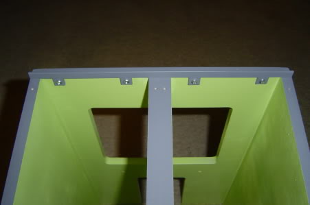
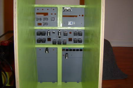
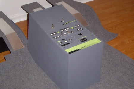
(Original thread started on 02-12-09 by Eric Tomlin) Some members reminded Ron and I that we needed to publish some important updates to the drawings of the TQ/Center Pedestals where there is an additional height placed on the bottom IF you are using certain design techniques like we are for the shell kit and a more realistic floor plan. The drawings that are currently posted up in the Resources section that show this are correct, but more for a Flat-Floor design where as for our shells we are making more of a sloped floor where we actually increase the shell's floor height by 1.5". As a result, we will publish an updated set of drawings for those that would like the info we are working with but please be patient as it all takes time to get drawn and posted. If you would like to get an idea of what I'm talking about have a look at the photo below and then imagine raising the center and throttle Pedestals up and also the floor being raised a bit too. This will all be made available soon. UPDATE: I wanted to let everyone know we have updated the drawings for the Center Pedestal/Throttle Pedestal and the MIP support portion of the Center Pedestal to show the sizes required for Ron's shell design. If you are building them without Ron's shell or concepts, then you can just use the drawings that are already loaded up. Make sure you pay attention to the correct version though because if you don't then you may have to start over. (Posted by Ron Rollo on 02-13-09) There are a few new members who are itching to start building something. That is why we are spending some time tweaking the drawings. Eric has taken my design work and put it into a 1 to 1 CAD drawing so that it can be printed out in full scale. It is up to the builders to transfer the design over to the material of their choice. (Aluminum, MDF, Birch Wood, Etc....) I included this Bitmap drawing to help illustrate how the three main pieces of the floor, TQ and Center pedestal mesh together. This is a very simple two dimensional drawing designed to get the main idea out to you. Please keep in mind that this is NOT how the real L45 is constructed, however, it is the easiest way for us to achieve the look and feel of the flight deck. Of course this design can also be used for folks who will not be using the shell. Feel free to use these drawings anyway you see fit so that it will work in your personal project. ****PLEASE USE THE DRAWINGS UPLOADED AT THE BOTTOM OF THIS THREAD!*** UPDATE: I have been working on the TQ pedestal and wanted to share a few pictures of the latest progress. In these two pictures, you will notice the 1/16th inch aluminum side access doors. Tom Goldberg cut these two parts with his waterjet based on drawings that Eric Tomlin created. Notice where I have the control column cross over notched out. I also made a cut at the bottom rear so that later on, I can interconnect my rudder pedal assembly! Next, I will be working on the Center Pedestal furniture: I used a nail gun (small light weight) which counter sinks the nails deep into the wood. Then with a little wood putty, you never know they are there. After some gray primer, a little sanding, and then the final coat of paint, these TQ's will be as smooth as aluminum! Super strong too! The other key is the type of wood to use. From what I had to choose from at Lowes (Hardware Store), I found that half inch Birch wood was the best. It is super smooth and the price was not bad. It sells for around $14.00 for a 2'X4' sheet. It takes a little less than three sheets to make the TQ Pedestal and the Center Pedestal. UPDATE: I just finished the main parts to the Center pedestal. It may look a little on the complex side, but in fact, I am trying to keep it simple! I used two pieces of .5" X 1" Birch to make the rail system. Also notice where the Center Pedestal is going to set on top of the raised floor under the seats. The notch at the bottom of the CP also acts as a "LOCK" and keeps it in place. There will also be two bolts holding the TQ and the CP together. I hope this information helps everyone in planning their Flight Deck: (Posted by Mark L. on 03-13-09) Nice job Ron! I'd like to point out a couple of things that need clarification for those of us working from the pics etc. On the resource page you mention the width of these 2 pieces but it doesn't indicate whether the width is outside or inside. I assume outside dimensions. Also the access panel cutouts from the drawing has a dashed line which I took to mean like a rabbit/recessed border of the cutout to provide a flush access panel cover mount. Which I had done. I had built mine out of 3/4 MDF which I believe will be fine. But it would help to clarify these points. (Posted by Eric Tomlin on 03-13-09) The dims are the outside dims Mark. Also the part isn't flush as best as I know- the dashed line is indicated on the Adams-Rite drawings and show just how much is touching the side and where the holes are. (Posted by Ron Rollo on 03-14-09) A picture or two is worth a thousand words! That's why I wanted to get this stuff done so you can also see what the final part(s) is going to look like. I will be working on the MIP backer, which will be MDF or Birch and then the MIP aluminum face plate made by Tom Goldberg. I can't wait to get it all together! We will make sure that as we actually make these parts that the drawings are updated with any new information and crystal clear for you guys who want to build their own stuff. This past week I have been working on developing the MIP stand backer support structure. So far it is coming together as planned. Here are a few tips to keep in mind when you guys are building your big hardware or "furniture": 1. Have a GREAT idea of the overall project. It's not something that you just throw together over a couple of weekends. It requires a lot of planning and thorough thought of all the components involved. 2. Use the drawings on the resources page. This will save you hundreds of hours of research, planning, scaling and development. The hard part is already done! 3. Build your unit from the ground up. Your can't work on the glare shield until the MIP is done, and you can't work on the MIP until the TQ is done. 4. Build your unit so that it is modular, meaning you can easily take it apart to move it from one place to another or work on a particular component or system. 5. Get the aluminum MIP and Glare shield from Tom Goldberg. These parts are worth every penny and a must for the build! Here are a few pictures of the work I recently completed this week: This is the MIP backer support structure standing alone: Here you can see the MIP backer support married up to the TQ WITHOUT the aluminum MIP in front of it: Notice how the Aluminum MIP lays perfectly flat on the MIP support. I have 1/8th inch foam strips between the two for sound dampening: (Keeps the rattles down) In this picture, you can see the 1.5" aluminum "L" beam that I have attach to back side of the "shin Plate" which is behind the lower panels. The three LCD screens will fit perfectly between the aluminum MIP and the MIP backer support like a sandwich: The aluminum MIP, believe it or not, is only going to be held in place with three bolts, (seen here.) The aluminum MIP rest firmly against the MIP structure and is surprisingly tight and secure. We don't want to ruin the look of the L45 with a bunch of screws in places that they don't belong! The Glare shield above, (not pictured yet) will also aid in holding the MIP in place. Hope you enjoy and it inspires! UPDATE: It's time to update everyone on the Center Pedestal and how the panels and some of the components are all fitting together. Two nights ago, I spent about an hour putting everything I had together just to see how it looks and all fits together. Man! I can't tell you how much fun that was, especially because it all went together so well. I had no issues and did not have to modify anything to get a switch or something to fit in correctly! (Keep in mind that I have only been planing these parts and making them for almost a year!) Here are some pictures of the latest updates: Here you can see that I have painted the Center Pedestal inside and out, because I am a nut about the very last detail: In this picture you can see clearly one of the two pedestal dividers that I made. The other one is just under the Engine start panel at the bend: Here you can see how most of the toggles, rotaries, and AML-21's all work together and do not clash with the pedestal structure: A close up view of some of the switches and all of the backer panels. Yes, all the plastic that you see here are just the backer panels painted. It may be several months before I get around to working on the face panels, but at least in the mean time, I can start slowly working on populating all the switches, wiring and interfacing. In some cases seen here, I just made a quick backer for nothing more but to find the attachment holes. We still have tons of research to do as far as figuring out what we are going to do with the WX panel, Trim pane and the HF panel as examples. Also seen in this last picture are the DZUS fasteners that I made about six weeks ago. I am getting close to saying that I am half way finished with my build! UPDATE: I just finished my third set of the inside "furniture" parts and I made them all with half inch Birch. As a matter of fact, this last set I am even making the MIP backer out of Birch where as Eric's and my MIP backer were made from half inch MDF. Over a year ago I made the mock-up components out of half inch MDF just to help prove angles and measurements. I would not recommend using MDF as a final product because it is almost impossible to sand and get the metal finish look. In a perfect world, I would make everything with 1/16th inch thick aluminum if I had a big break and Tom as a next door neighbor! (Posted by Shane Barnes on 09-10-09) I'm going to take a shot in the dark here and Ron can correct me if I am wrong, but I would say he used 1/2 inch due to space considerations for the switches that will populate the panels. If you take a look at his photos from the underneath side, you will see that the switches are getting real close to the sides. (Posted by Ron Rollo on 09-11-09) You are correct Shane. We need as much room as we can spare without compromising the strength of the parts we are building. The last thing your gonna want to do is have to chisel out notches in your wood to make room for switch bodies. (I had to do this when I build my flight box. I even used .5".) The TQ is particularly critical when it comes to space. As a matter of fact, .5" is too thick for the flaps arm. Here you can either mill down the wood to .25" or just move the flaps arm over to the left. As far as the strength of the .5" Birch, it is plenty strong enough to handle any abuse you can throw at it. It does not flex what so ever. Even the TQ where it gets very thin at the front end near the center pedestal area. NOTE: The real Lear45 uses aluminum that can't be any thicker than .0625". You can find all the .dxf CAD files for the Center Pedestal, TQ Pedestal, MIP Tower, MIP Backer and the Raised Floor System in the Builder Resources page. (Original thread started on 02-12-09 by Eric Tomlin) Some members reminded Ron and I that we needed to publish some important updates to the drawings of the TQ/Center Pedestals where there is an additional height placed on the bottom IF you are using certain design techniques like we are for the shell kit and a more realistic floor plan. The drawings that are currently posted up in the Resources section that show this are correct, but more for a Flat-Floor design where as for our shells we are making more of a sloped floor where we actually increase the shell's floor height by 1.5". As a result, we will publish an updated set of drawings for those that would like the info we are working with but please be patient as it all takes time to get drawn and posted. If you would like to get an idea of what I'm talking about have a look at the photo below and then imagine raising the center and throttle Pedestals up and also the floor being raised a bit too. This will all be made available soon. UPDATE: I wanted to let everyone know we have updated the drawings for the Center Pedestal/Throttle Pedestal and the MIP support portion of the Center Pedestal to show the sizes required for Ron's shell design. If you are building them without Ron's shell or concepts, then you can just use the drawings that are already loaded up. Make sure you pay attention to the correct version though because if you don't then you may have to start over. (Posted by Ron Rollo on 02-13-09) There are a few new members who are itching to start building something. That is why we are spending some time tweaking the drawings. Eric has taken my design work and put it into a 1 to 1 CAD drawing so that it can be printed out in full scale. It is up to the builders to transfer the design over to the material of their choice. (Aluminum, MDF, Birch Wood, Etc....) I included this Bitmap drawing to help illustrate how the three main pieces of the floor, TQ and Center pedestal mesh together. This is a very simple two dimensional drawing designed to get the main idea out to you. Please keep in mind that this is NOT how the real L45 is constructed, however, it is the easiest way for us to achieve the look and feel of the flight deck. Of course this design can also be used for folks who will not be using the shell. Feel free to use these drawings anyway you see fit so that it will work in your personal project. ****PLEASE USE THE DRAWINGS UPLOADED AT THE BOTTOM OF THIS THREAD!*** UPDATE: I have been working on the TQ pedestal and wanted to share a few pictures of the latest progress. In these two pictures, you will notice the 1/16th inch aluminum side access doors. Tom Goldberg cut these two parts with his waterjet based on drawings that Eric Tomlin created. Notice where I have the control column cross over notched out. I also made a cut at the bottom rear so that later on, I can interconnect my rudder pedal assembly! Next, I will be working on the Center Pedestal furniture: I used a nail gun (small light weight) which counter sinks the nails deep into the wood. Then with a little wood putty, you never know they are there. After some gray primer, a little sanding, and then the final coat of paint, these TQ's will be as smooth as aluminum! Super strong too! The other key is the type of wood to use. From what I had to choose from at Lowes (Hardware Store), I found that half inch Birch wood was the best. It is super smooth and the price was not bad. It sells for around $14.00 for a 2'X4' sheet. It takes a little less than three sheets to make the TQ Pedestal and the Center Pedestal. UPDATE: I just finished the main parts to the Center pedestal. It may look a little on the complex side, but in fact, I am trying to keep it simple! I used two pieces of .5" X 1" Birch to make the rail system. Also notice where the Center Pedestal is going to set on top of the raised floor under the seats. The notch at the bottom of the CP also acts as a "LOCK" and keeps it in place. There will also be two bolts holding the TQ and the CP together. I hope this information helps everyone in planning their Flight Deck: (Posted by Mark L. on 03-13-09) Nice job Ron! I'd like to point out a couple of things that need clarification for those of us working from the pics etc. On the resource page you mention the width of these 2 pieces but it doesn't indicate whether the width is outside or inside. I assume outside dimensions. Also the access panel cutouts from the drawing has a dashed line which I took to mean like a rabbit/recessed border of the cutout to provide a flush access panel cover mount. Which I had done. I had built mine out of 3/4 MDF which I believe will be fine. But it would help to clarify these points. (Posted by Eric Tomlin on 03-13-09) The dims are the outside dims Mark. Also the part isn't flush as best as I know- the dashed line is indicated on the Adams-Rite drawings and show just how much is touching the side and where the holes are. (Posted by Ron Rollo on 03-14-09) A picture or two is worth a thousand words! That's why I wanted to get this stuff done so you can also see what the final part(s) is going to look like. I will be working on the MIP backer, which will be MDF or Birch and then the MIP aluminum face plate made by Tom Goldberg. I can't wait to get it all together! We will make sure that as we actually make these parts that the drawings are updated with any new information and crystal clear for you guys who want to build their own stuff. This past week I have been working on developing the MIP stand backer support structure. So far it is coming together as planned. Here are a few tips to keep in mind when you guys are building your big hardware or "furniture": 1. Have a GREAT idea of the overall project. It's not something that you just throw together over a couple of weekends. It requires a lot of planning and thorough thought of all the components involved. 2. Use the drawings on the resources page. This will save you hundreds of hours of research, planning, scaling and development. The hard part is already done! 3. Build your unit from the ground up. Your can't work on the glare shield until the MIP is done, and you can't work on the MIP until the TQ is done. 4. Build your unit so that it is modular, meaning you can easily take it apart to move it from one place to another or work on a particular component or system. 5. Get the aluminum MIP and Glare shield from Tom Goldberg. These parts are worth every penny and a must for the build! Here are a few pictures of the work I recently completed this week: This is the MIP backer support structure standing alone: Here you can see the MIP backer support married up to the TQ WITHOUT the aluminum MIP in front of it: Notice how the Aluminum MIP lays perfectly flat on the MIP support. I have 1/8th inch foam strips between the two for sound dampening: (Keeps the rattles down) In this picture, you can see the 1.5" aluminum "L" beam that I have attach to back side of the "shin Plate" which is behind the lower panels. The three LCD screens will fit perfectly between the aluminum MIP and the MIP backer support like a sandwich: The aluminum MIP, believe it or not, is only going to be held in place with three bolts, (seen here.) The aluminum MIP rest firmly against the MIP structure and is surprisingly tight and secure. We don't want to ruin the look of the L45 with a bunch of screws in places that they don't belong! The Glare shield above, (not pictured yet) will also aid in holding the MIP in place. Hope you enjoy and it inspires! UPDATE: It's time to update everyone on the Center Pedestal and how the panels and some of the components are all fitting together. Two nights ago, I spent about an hour putting everything I had together just to see how it looks and all fits together. Man! I can't tell you how much fun that was, especially because it all went together so well. I had no issues and did not have to modify anything to get a switch or something to fit in correctly! (Keep in mind that I have only been planing these parts and making them for almost a year!) Here are some pictures of the latest updates: Here you can see that I have painted the Center Pedestal inside and out, because I am a nut about the very last detail: In this picture you can see clearly one of the two pedestal dividers that I made. The other one is just under the Engine start panel at the bend: Here you can see how most of the toggles, rotaries, and AML-21's all work together and do not clash with the pedestal structure: A close up view of some of the switches and all of the backer panels. Yes, all the plastic that you see here are just the backer panels painted. It may be several months before I get around to working on the face panels, but at least in the mean time, I can start slowly working on populating all the switches, wiring and interfacing. In some cases seen here, I just made a quick backer for nothing more but to find the attachment holes. We still have tons of research to do as far as figuring out what we are going to do with the WX panel, Trim pane and the HF panel as examples. Also seen in this last picture are the DZUS fasteners that I made about six weeks ago. I am getting close to saying that I am half way finished with my build! UPDATE: I just finished my third set of the inside "furniture" parts and I made them all with half inch Birch. As a matter of fact, this last set I am even making the MIP backer out of Birch where as Eric's and my MIP backer were made from half inch MDF. Over a year ago I made the mock-up components out of half inch MDF just to help prove angles and measurements. I would not recommend using MDF as a final product because it is almost impossible to sand and get the metal finish look. In a perfect world, I would make everything with 1/16th inch thick aluminum if I had a big break and Tom as a next door neighbor! (Posted by Shane Barnes on 09-10-09) I'm going to take a shot in the dark here and Ron can correct me if I am wrong, but I would say he used 1/2 inch due to space considerations for the switches that will populate the panels. If you take a look at his photos from the underneath side, you will see that the switches are getting real close to the sides. (Posted by Ron Rollo on 09-11-09) You are correct Shane. We need as much room as we can spare without compromising the strength of the parts we are building. The last thing your gonna want to do is have to chisel out notches in your wood to make room for switch bodies. (I had to do this when I build my flight box. I even used .5".) The TQ is particularly critical when it comes to space. As a matter of fact, .5" is too thick for the flaps arm. Here you can either mill down the wood to .25" or just move the flaps arm over to the left. As far as the strength of the .5" Birch, it is plenty strong enough to handle any abuse you can throw at it. It does not flex what so ever. Even the TQ where it gets very thin at the front end near the center pedestal area. NOTE: The real Lear45 uses aluminum that can't be any thicker than .0625". You can find all the .dxf CAD files for the Center Pedestal, TQ Pedestal, MIP Tower, MIP Backer and the Raised Floor System in the Builder Resources page. I have several 15" monitors which I tried to use for the center MIP monitor. Obviously it didn't work as it is 10" high and the max width is 8.5". I found one 18" LCD at PCLiquidators. They had one left. This size monitor is now rare and many vendors are out of stock. There are 18" portable monitors for a tablet but are expensive at $135 to $300. May I suggest the driving engineers of this Sim find an alternative for future simmers. Maybe the hardware and controls drawings need updating for an alternative. Ten inch screens with hdmi are running at $125. Thanks I have several 15" monitors which I tried to use for the center MIP monitor. Obviously it didn't work as it is 10" high and the max width is 8.5". I found one 18" LCD at PCLiquidators. They had one left. This size monitor is now rare and many vendors are out of stock. There are 18" portable monitors for a tablet but are expensive at $135 to $300. May I suggest the driving engineers of this Sim find an alternative for future simmers. Maybe the hardware and controls drawings need updating for an alternative. Ten inch screens with hdmi are running at $125. Thanks Hey Dave, the old plan for the center monitor was to use a 15.6" WIDESCREEN LCD screen. A standard 15 LCD screen will not work. And yes, even the 15.6" Widescreen LCD sticks up high at the top, but it is covered and behind the glare shield when built properly. The bigger issue is when the center screen is viewed from the FO seat, there is significant distortion, making it look terrible. This has always been an issue and needed to be addressed. And now it has....... The new and improved v2.0 method will be to use two 9 inch LCD screens with HDMI. You can get them here for under $30 each free shipping HERE Check out this thread and look at the last post HERE This new solution will address the problem with distortion and also the minor issue of the old 15.6" screen being tall and needing to be hidden behind the glare shield. This new solution is actually one of two new solutions. The second solution would be to use mechanical gauges from Flight Illusions for the three standbys. But it would still require one 9" LCD screen for the RMUs. (I do not recommend to anyone to use a 18" monitor or any other size other than the two 15" standard screens for left and right display units and what I have posted above for the center screens. Any other size will get you painted into a corner and you may not realize it until you are too far down the path.) Hey Dave, the old plan for the center monitor was to use a 15.6" WIDESCREEN LCD screen. A standard 15 LCD screen will not work. And yes, even the 15.6" Widescreen LCD sticks up high at the top, but it is covered and behind the glare shield when built properly. The bigger issue is when the center screen is viewed from the FO seat, there is significant distortion, making it look terrible. This has always been an issue and needed to be addressed. And now it has....... The new and improved v2.0 method will be to use two 9 inch LCD screens with HDMI. You can get them here for under $30 each free shipping HERE Check out this thread and look at the last post HERE This new solution will address the problem with distortion and also the minor issue of the old 15.6" screen being tall and needing to be hidden behind the glare shield. This new solution is actually one of two new solutions. The second solution would be to use mechanical gauges from Flight Illusions for the three standbys. But it would still require one 9" LCD screen for the RMUs. (I do not recommend to anyone to use a 18" monitor or any other size other than the two 15" standard screens for left and right display units and what I have posted above for the center screens. Any other size will get you painted into a corner and you may not realize it until you are too far down the path.) That is true! And you DID warn me Ron 😉 That is true! And you DID warn me Ron 😉 Thanks all, Appreciate the feedback. For some reason, PC Liquidators refunded my PayPal payment with no explanation. I ordered 2 9 inch monitors thru Amazon at $33 each. Free shipping by 12/15. $21 shipping next week. Powered by USB. The Ali Express monitors take 39 days. Does anyone have the layout for the 9 inch MIP backer? No need to reinvent the wheel. If not, I'll do my best. Thanks all, Appreciate the feedback. For some reason, PC Liquidators refunded my PayPal payment with no explanation. I ordered 2 9 inch monitors thru Amazon at $33 each. Free shipping by 12/15. $21 shipping next week. Powered by USB. The Ali Express monitors take 39 days. Does anyone have the layout for the 9 inch MIP backer? No need to reinvent the wheel. If not, I'll do my best. Hi Dave. I tried these 9” screens from ALiExpress... but i found the lack of brightness and contrast to be too noticeable, so I switched back to the 16” I mounted the 9“ (screen only, no case) using aluminium “U” channel which I doubled-sided tape directly to the back of the MIP. This was holding the left and right sides of the screens. I got the channel from a local hobby shop. It was a loose fit in the slot, but i added cloth tape to the slot to get a good fit. I found the screens fitted nicely when stacked one directly on the other, so I made the channel one piece per side and just slipped the screens in from the top. You need to ensure the CWP wiring is as flat as possible to do this. I rewired the CWP with ribbon cable to get it sitting flat enough. This also means no stuffing around with the MIP backer as it fits fully within the cutout for a 16” screen. I dont have any photos but can mock up the concept if you need. Hi Dave. I tried these 9” screens from ALiExpress... but i found the lack of brightness and contrast to be too noticeable, so I switched back to the 16” I mounted the 9“ (screen only, no case) using aluminium “U” channel which I doubled-sided tape directly to the back of the MIP. This was holding the left and right sides of the screens. I got the channel from a local hobby shop. It was a loose fit in the slot, but i added cloth tape to the slot to get a good fit. I found the screens fitted nicely when stacked one directly on the other, so I made the channel one piece per side and just slipped the screens in from the top. You need to ensure the CWP wiring is as flat as possible to do this. I rewired the CWP with ribbon cable to get it sitting flat enough. This also means no stuffing around with the MIP backer as it fits fully within the cutout for a 16” screen. I dont have any photos but can mock up the concept if you need. Hey Dave, Go to the BUILDER RESOURCES page and down load the MIP Backer / Tower v2.0 file. You will find a drawing that will work for your needs. Will, I am curious as to how bad you thought the brightness was or lack of and contrast. Did you have a smoked lens in front of the LCD display and were you able to adjust those settings? I have not actually fired mine up but it looks like I probably need to. Worse case is I would need to pick up a couple more from another source. Hey Dave, Go to the BUILDER RESOURCES page and down load the MIP Backer / Tower v2.0 file. You will find a drawing that will work for your needs. Will, I am curious as to how bad you thought the brightness was or lack of and contrast. Did you have a smoked lens in front of the LCD display and were you able to adjust those settings? I have not actually fired mine up but it looks like I probably need to. Worse case is I would need to pick up a couple more from another source. Hey Ron, Yes, i had them at full bright, and still the difference was too much. I bought 3 of them and all were the same problem. I even considered getting some of the same for the DU’s as I found a size that would fit and dispose of the 16”, but the issue of rotated screens remained just with cheaper screens! that being said, there are better (more expensive ) 9” screens out there. I have not tried this approach yet. Hey Ron, Yes, i had them at full bright, and still the difference was too much. I bought 3 of them and all were the same problem. I even considered getting some of the same for the DU’s as I found a size that would fit and dispose of the 16”, but the issue of rotated screens remained just with cheaper screens! that being said, there are better (more expensive ) 9” screens out there. I have not tried this approach yet. I'm quite happy with the smaller 9" screen though it does have a different contrast than the 2 15" we use for the DUs. It's most noticeable when the avionics are "OFF" where the 15" monitor are quite dark and the small 9" monitor has a glow. It's a toss up though, if we are moving toward hardware standby gauges this is something we have to contend with. There are several companies that produce real avionics monitors that you can get incredible brightness and contrast, but you will spend $500+ for them. AvionicsLCD.com is the one I'm most familiar with. I'm quite happy with the smaller 9" screen though it does have a different contrast than the 2 15" we use for the DUs. It's most noticeable when the avionics are "OFF" where the 15" monitor are quite dark and the small 9" monitor has a glow. It's a toss up though, if we are moving toward hardware standby gauges this is something we have to contend with. There are several companies that produce real avionics monitors that you can get incredible brightness and contrast, but you will spend $500+ for them. AvionicsLCD.com is the one I'm most familiar with. The difficulty I'm having is finding a 16:9 15" monitor that doesn't cost more than $200. I purchase a 15" from eBay for $40 but when it arrived it was 4:3 (obviously doesn't fit). As a retiree, I don't want to put $$$$$ into this effort. I'm more interested in flying than building a duplicate. Does anyone have any suggestion or have an extra they would like to sell? Thanks The difficulty I'm having is finding a 16:9 15" monitor that doesn't cost more than $200. I purchase a 15" from eBay for $40 but when it arrived it was 4:3 (obviously doesn't fit). As a retiree, I don't want to put $$$$$ into this effort. I'm more interested in flying than building a duplicate. Does anyone have any suggestion or have an extra they would like to sell? ThanksCenter, TQ Ped and MIP by Project45
![]()
![]()
![]()
![]()
My 17" left and right screens are too big :S
I thought it might fit, but now i am creating my Chrono's and GPWS anunciators and even for those last there is a space issue .
I am going to replace them .
My 17" left and right screens are too big :S
I thought it might fit, but now i am creating my Chrono's and GPWS anunciators and even for those last there is a space issue .
I am going to replace them .![]()
![]()
![]()
![]()
![]()
![]()
Forum NavigationCenter, TQ Ped and MIP by Project45
![]() #1 · December 13, 2017, 7:48 am
#1 · December 13, 2017, 7:48 am![]() #2 · October 29, 2020, 8:18 pm
#2 · October 29, 2020, 8:18 pm![]() #3 · October 30, 2020, 8:16 am
#3 · October 30, 2020, 8:16 am![]() #4 · October 30, 2020, 1:38 pm
#4 · October 30, 2020, 1:38 pm![]() #5 · October 30, 2020, 5:37 pm
#5 · October 30, 2020, 5:37 pm![]() #6 · October 31, 2020, 3:13 am
#6 · October 31, 2020, 3:13 am![]() #7 · October 31, 2020, 6:44 pm
#7 · October 31, 2020, 6:44 pm![]() #8 · November 3, 2020, 3:09 pm
#8 · November 3, 2020, 3:09 pm![]() #9 · November 3, 2020, 3:24 pmJason Hite
FlightDeckSoft
#9 · November 3, 2020, 3:24 pmJason Hite
FlightDeckSoft![]() #10 · November 6, 2020, 8:10 pm
#10 · November 6, 2020, 8:10 pm
2017-10-10