


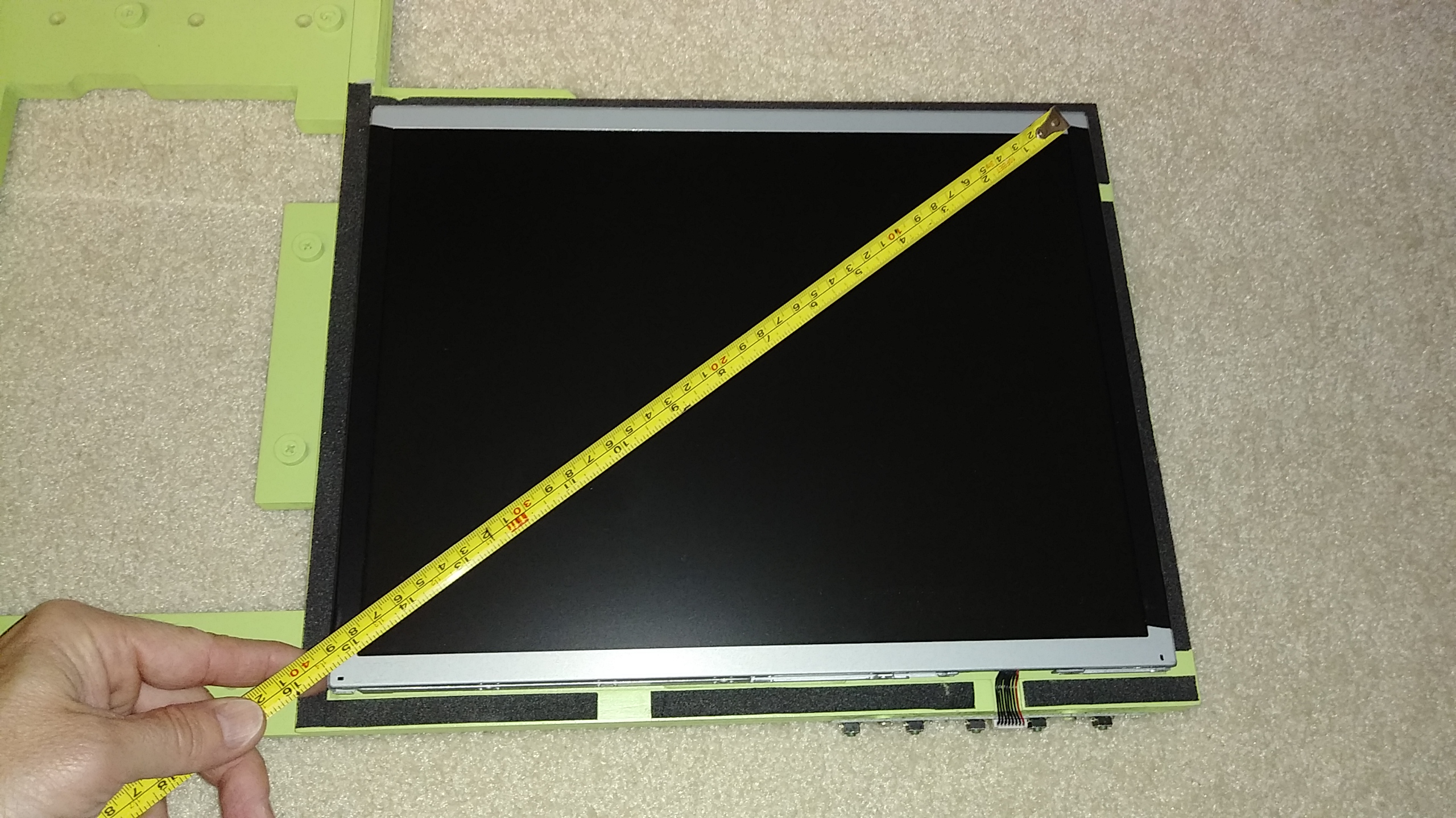
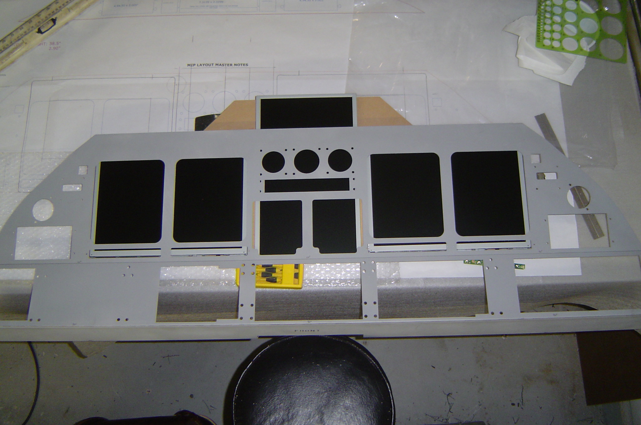
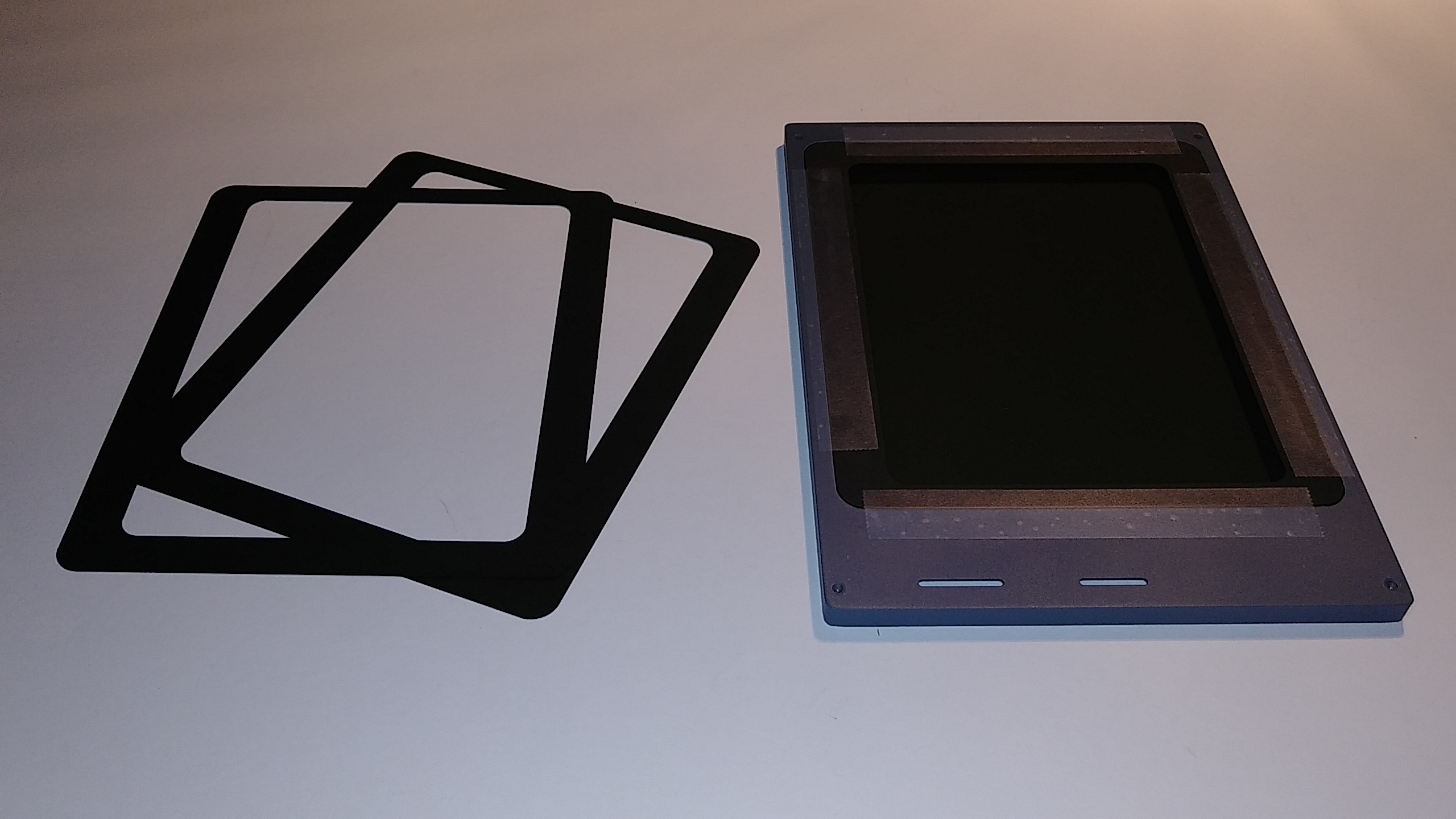
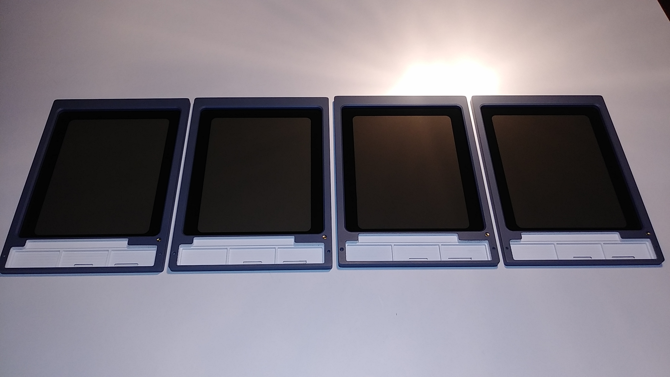
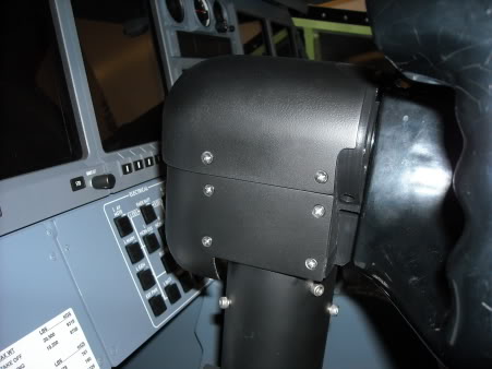
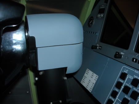
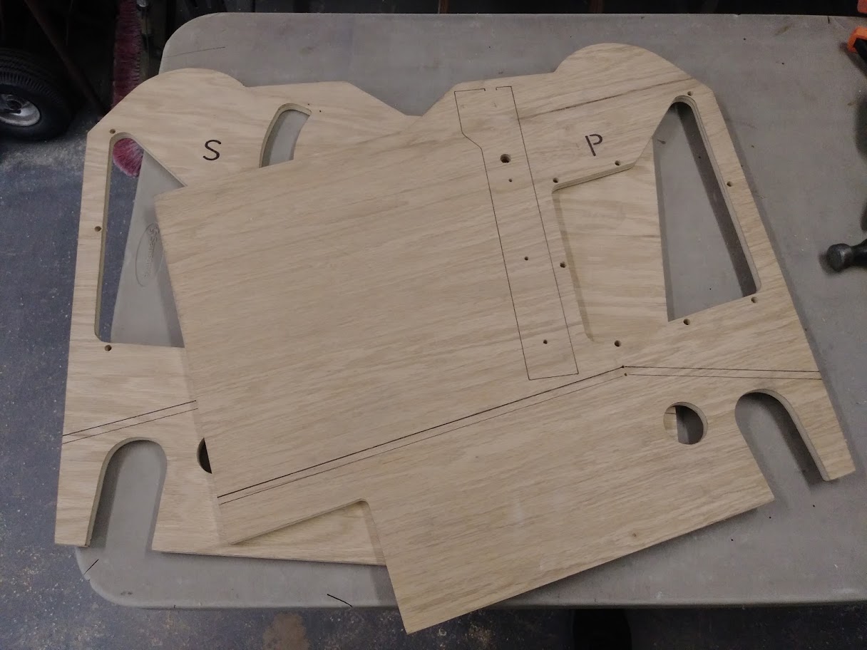
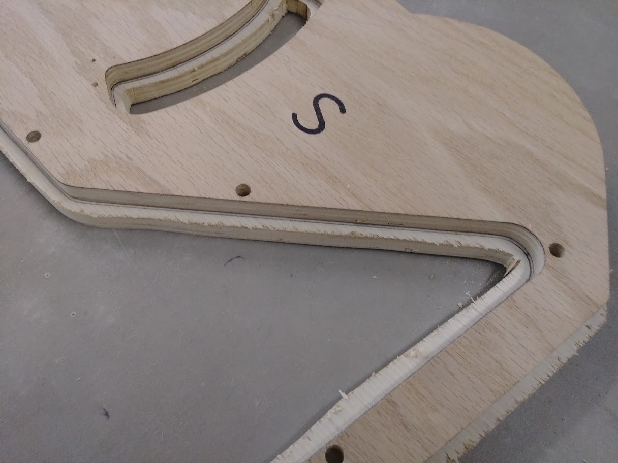
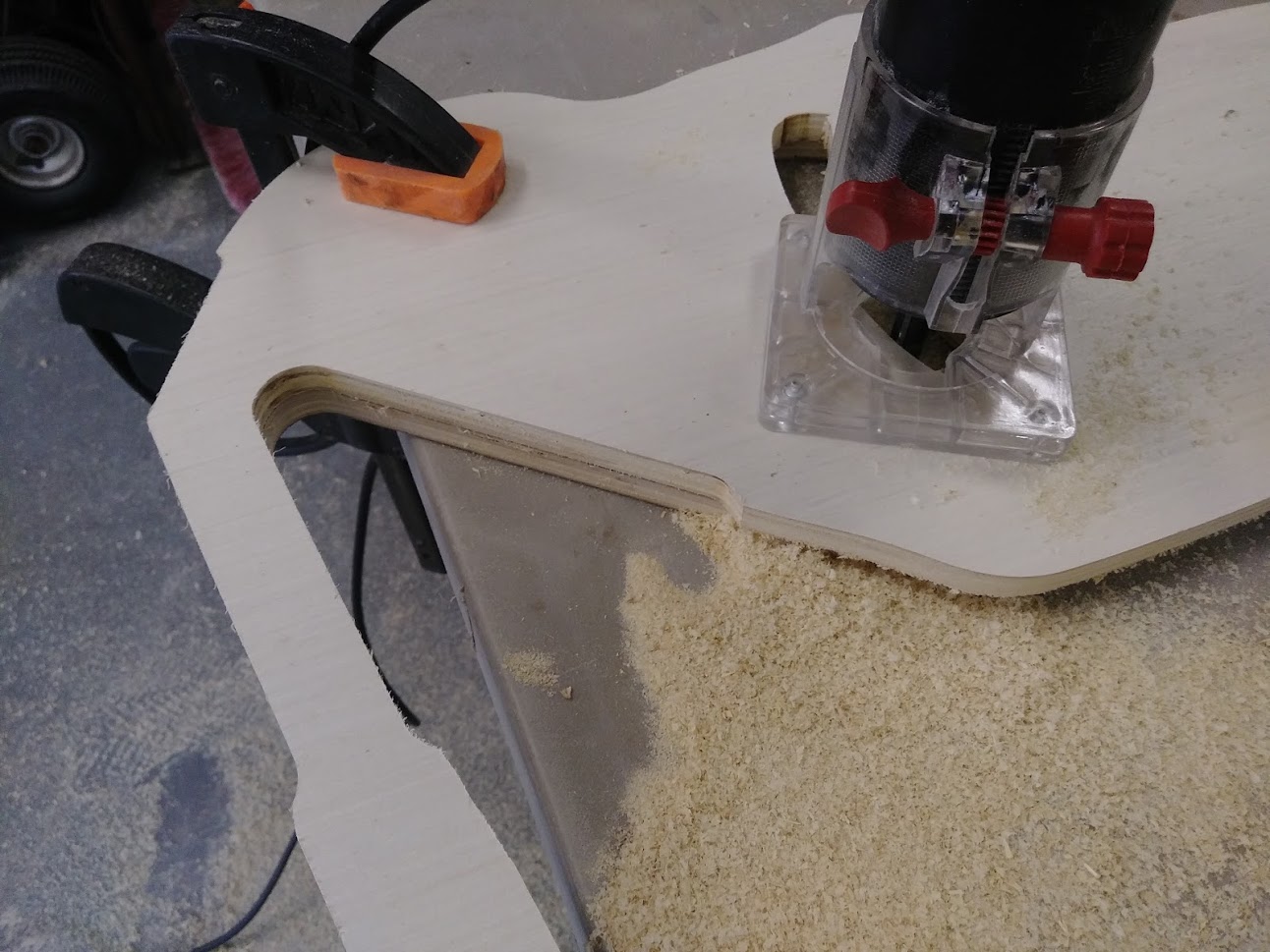
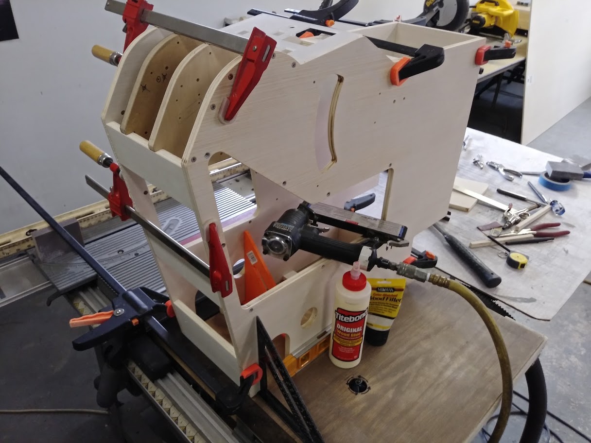
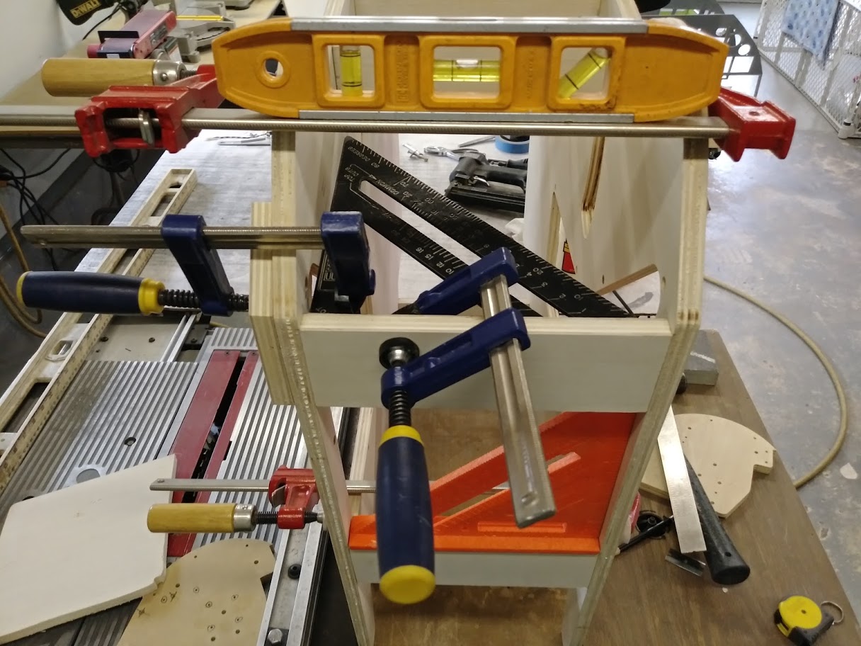
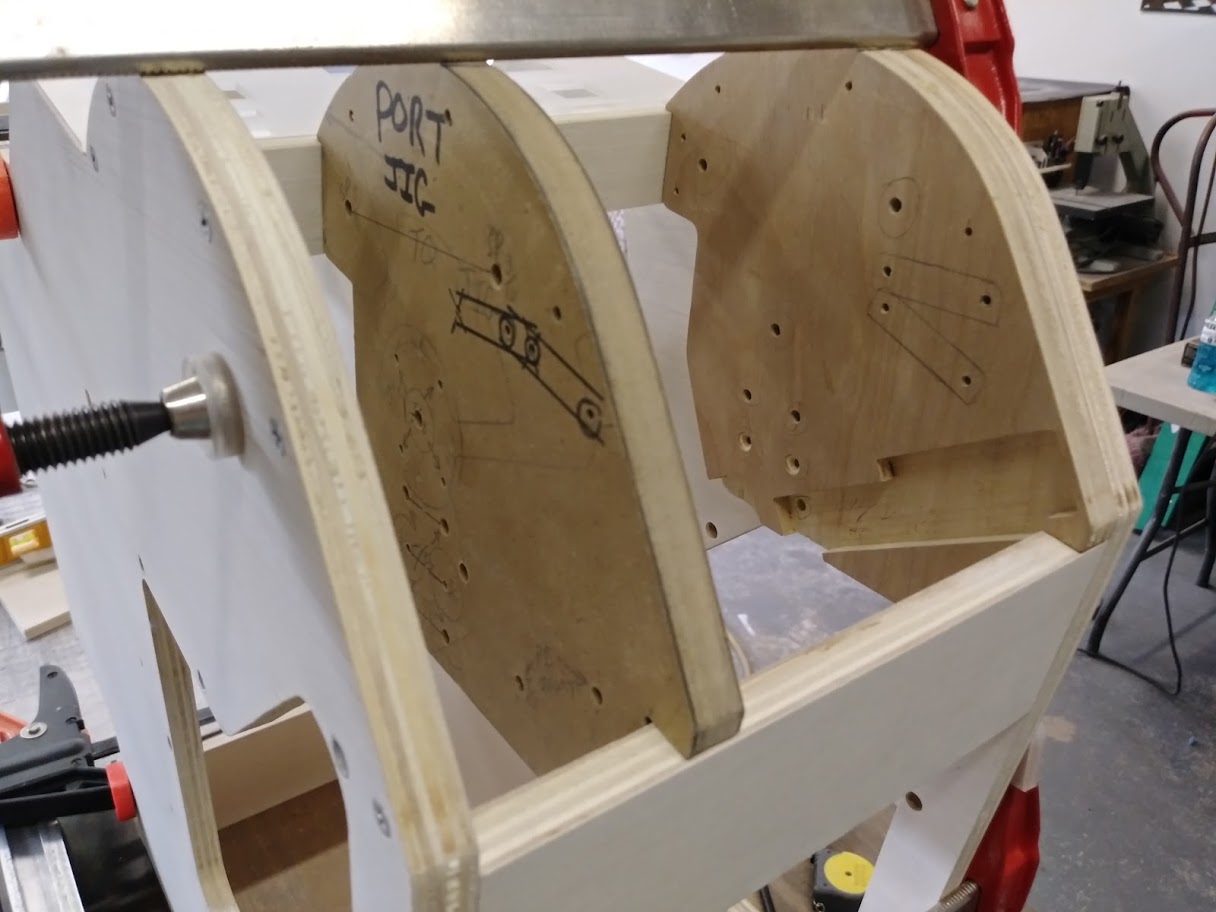
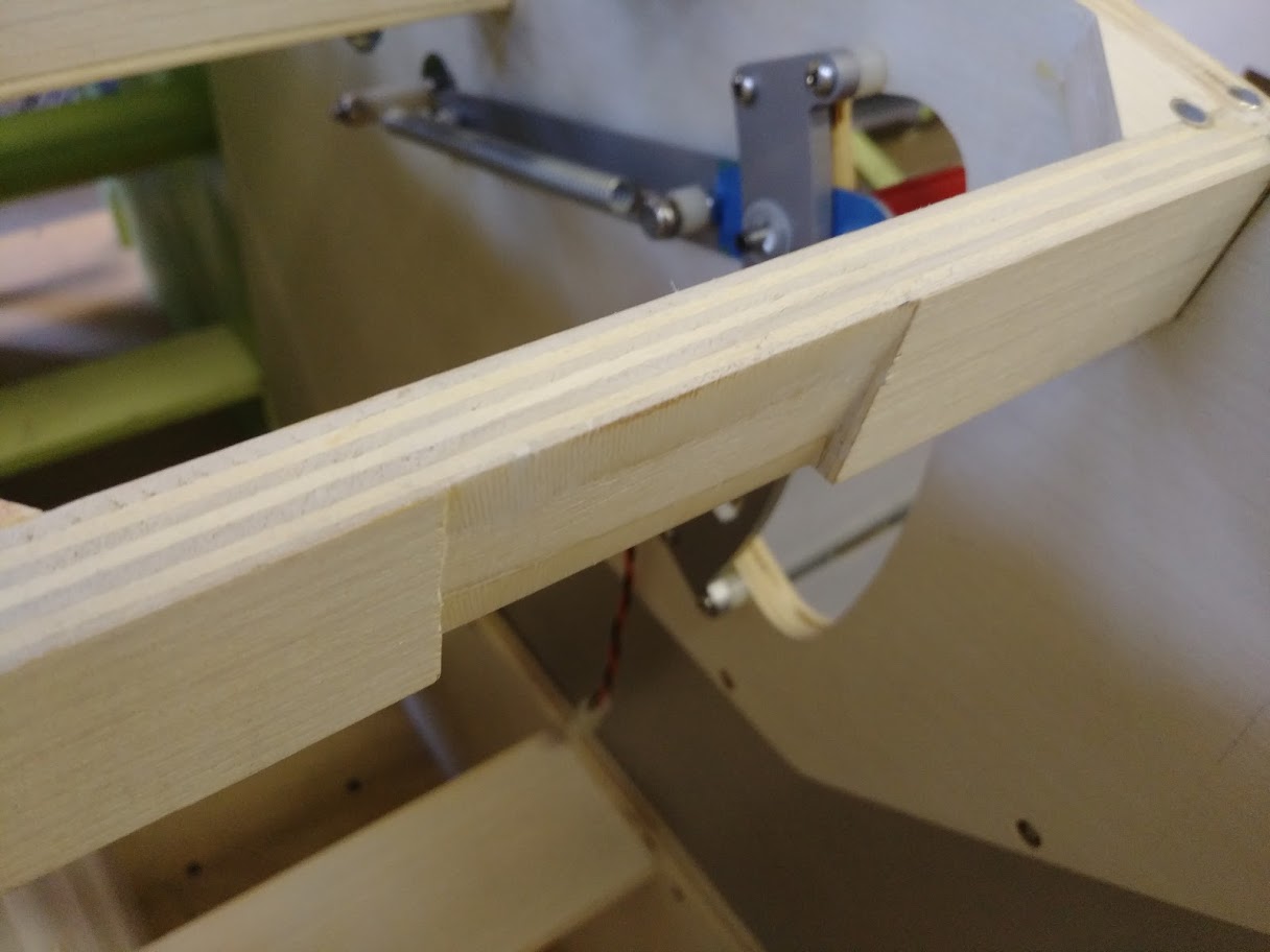
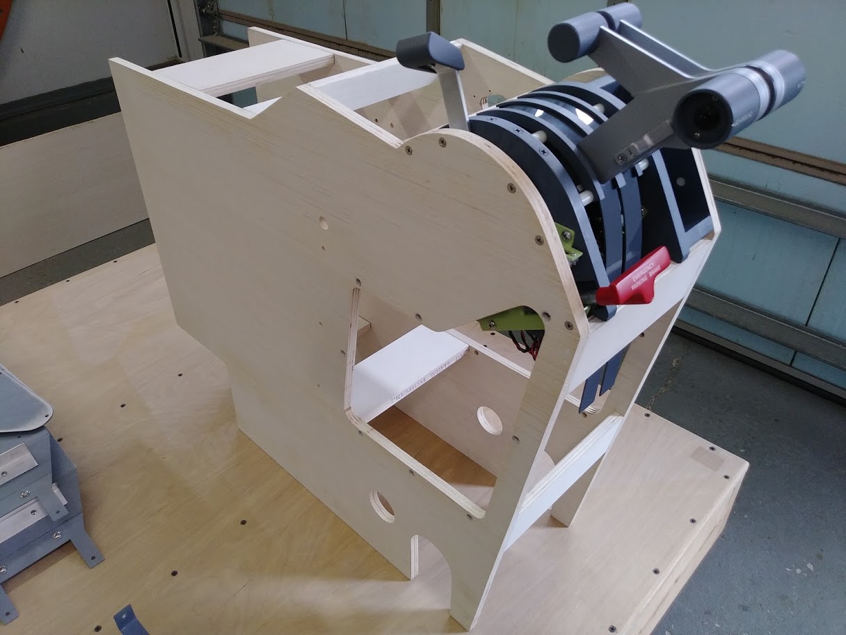
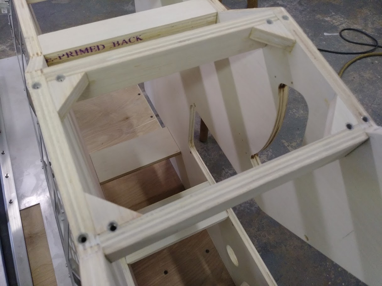
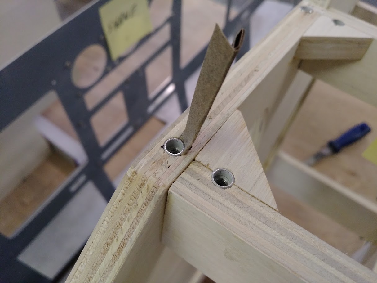
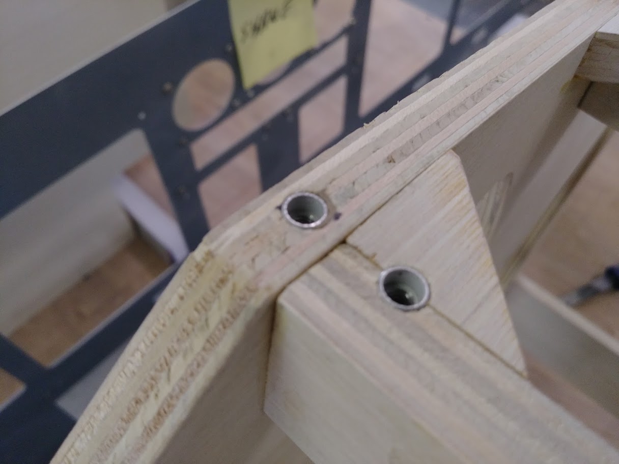
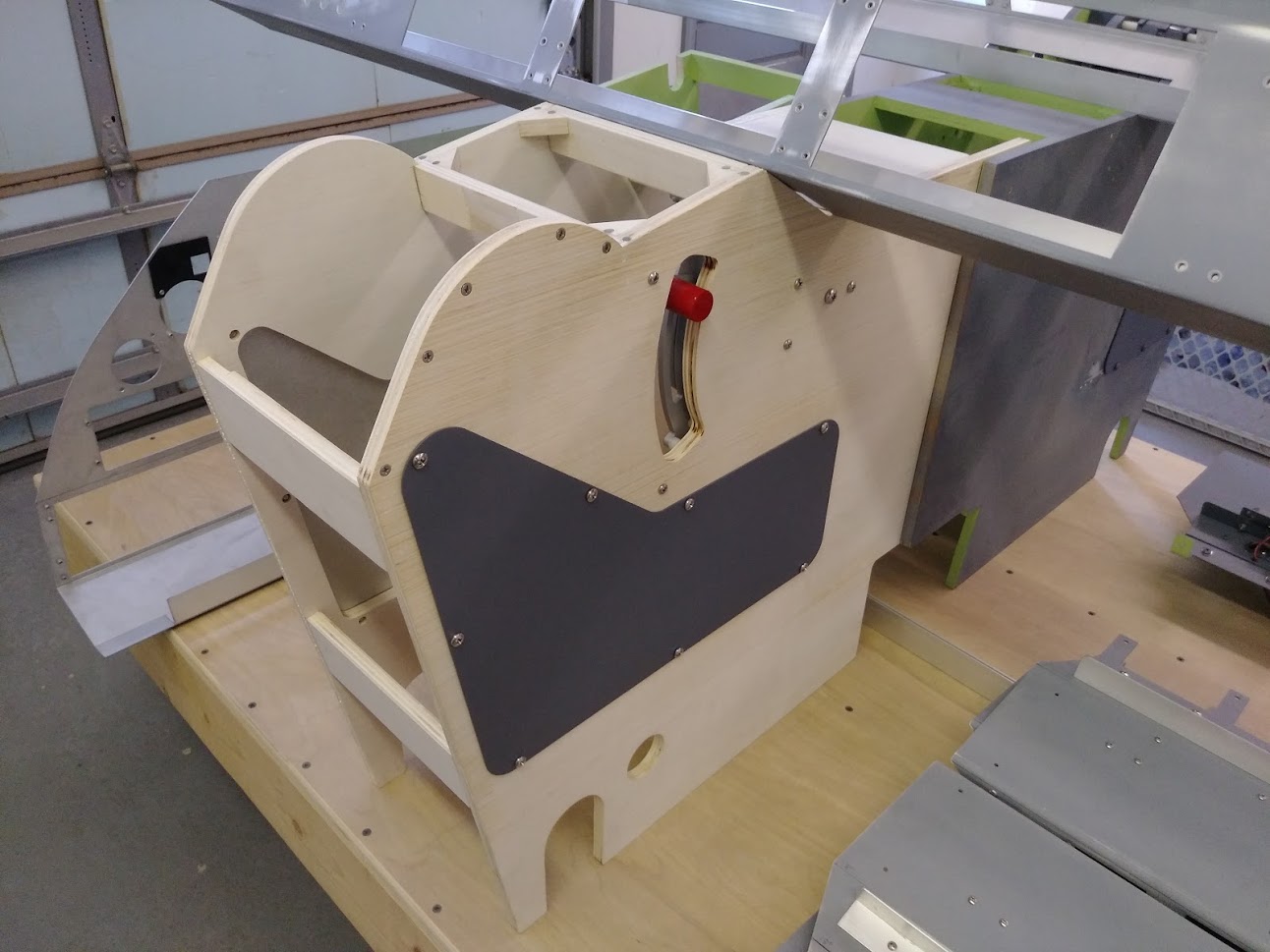
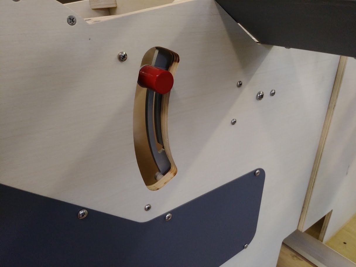
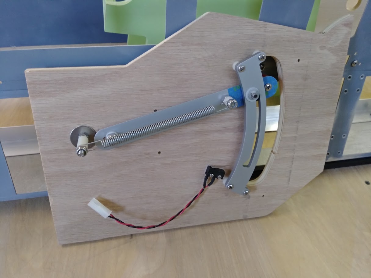
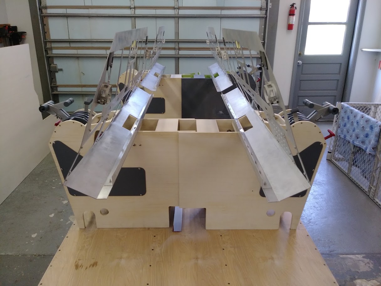
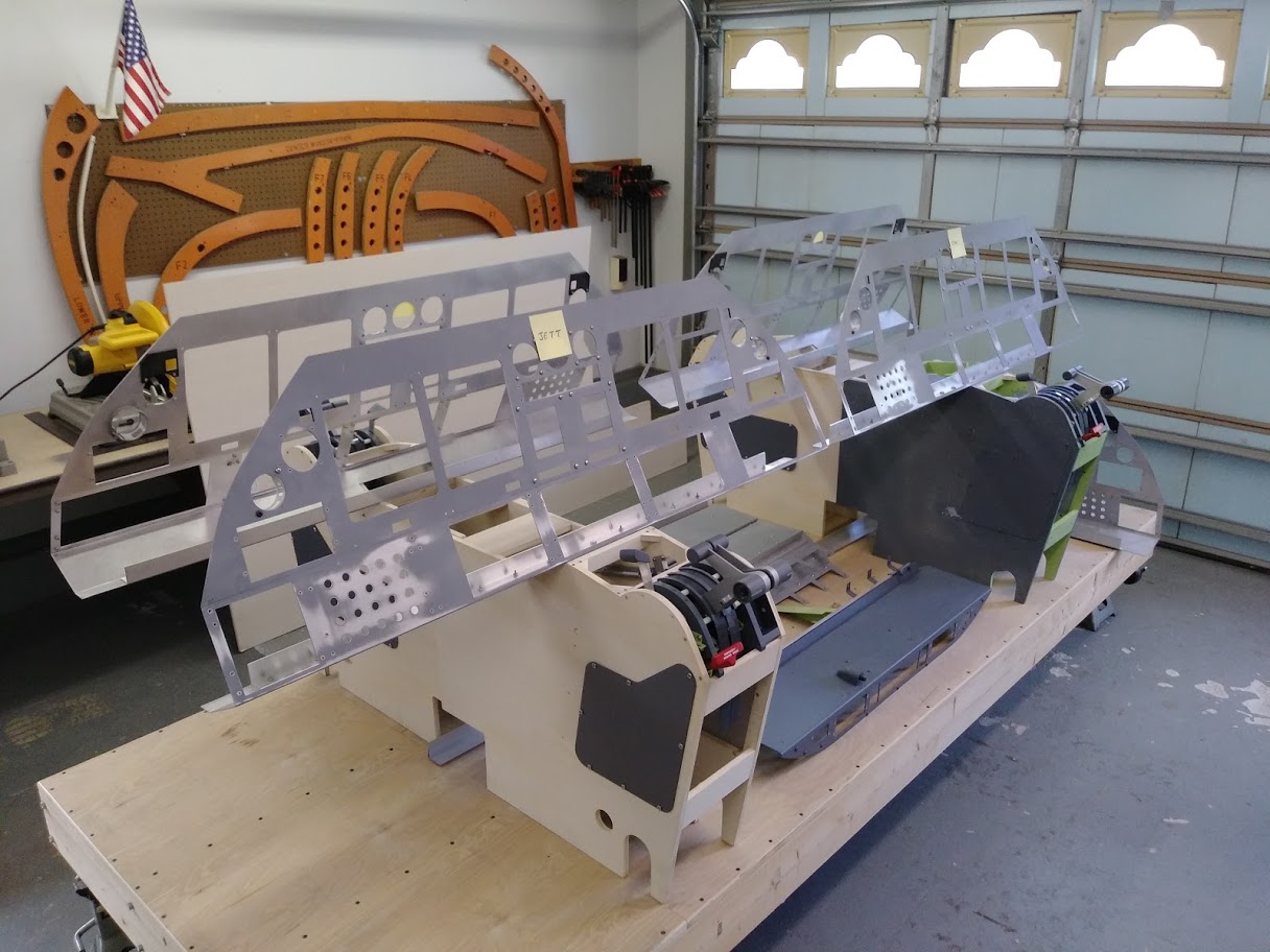
Hey Dave, You need to be searching for 15.6" Widescreen LCDs. Like this used ASUS 15.6 Widescreen on eBay HERE But, being that I am practically in the same boat as you are and I am rebuilding my MIP with center monitor(s), I would go with the 9" screen in landscape mode. The side distortion will drive you crazy. Hey Dave, You need to be searching for 15.6" Widescreen LCDs. Like this used ASUS 15.6 Widescreen on eBay HERE But, being that I am practically in the same boat as you are and I am rebuilding my MIP with center monitor(s), I would go with the 9" screen in landscape mode. The side distortion will drive you crazy. Sorry Ron, I purchased the 9" monitors for the center. I was talking about the 15" monitor for the left or right. I didn't notice the ratio and bought a used 4:3 unit for $25. When that didn't fit, I realized that I need the 15" with a 16:9 size ratio. Can't find one that is older and used (most are 4:3). The 16:9 that are offered are new and the price is $150 or above. I may have to use a 16" that I have and such it up on the Davtron. If anyone has a used left or right 15" spare, please let me know. Thanks Sorry Ron, I purchased the 9" monitors for the center. I was talking about the 15" monitor for the left or right. I didn't notice the ratio and bought a used 4:3 unit for $25. When that didn't fit, I realized that I need the 15" with a 16:9 size ratio. Can't find one that is older and used (most are 4:3). The 16:9 that are offered are new and the price is $150 or above. I may have to use a 16" that I have and such it up on the Davtron. If anyone has a used left or right 15" spare, please let me know. Thanks Dave, Do you have a custom monitor tower? Ron's design uses a 4:3 15" monitor for the DUs. Most of the rest of us are using 15" monitors for the DU. Dave, Do you have a custom monitor tower? Ron's design uses a 4:3 15" monitor for the DUs. Most of the rest of us are using 15" monitors for the DU. Hey Dave, As Jason just mentioned, the correct size for the LCD monitors behind the Display Units are 15" standard 4:3. You might be thinking it is not the right size because maybe you do not have your Display Units installed yet or maybe you have the DUs intalled and they do not cover up the metal edges of the LCD screen. This photo shows the raw Aluminum MIP, MIP Backer and the two 15" Standard LCD screens. Notice that the metal edges of the LCD screens are running along the left and right edges? And it looks like the screens are too low. All this is okay if you are using our Display Unit building method. If your DU bezels are the correct size and you are using what I call a "Bezel Mask" which in the case of the DUs that I make are made of construction paper, everything should fit perfectly. Things are very tight but perfect. The 15" standard LCD screen is the only option to make EVERYTHING fit perfectly including things like the Davtron clocks and the GPWS indicators. As you can see from the photo below, the Display Units have all their switch hardware built into the bottom of the bezels. This way nothing is interfering with the monitors behind the MIP. You can also see how the Bezel Mask gives the Display Units their desired look and also perfectly hide the metal edges of the LCD screens behind the MIP. I hope this clears things up. If not, please post some photos of the issues you are having and maybe I can help you with what is not going right. Hey Dave, As Jason just mentioned, the correct size for the LCD monitors behind the Display Units are 15" standard 4:3. You might be thinking it is not the right size because maybe you do not have your Display Units installed yet or maybe you have the DUs intalled and they do not cover up the metal edges of the LCD screen. This photo shows the raw Aluminum MIP, MIP Backer and the two 15" Standard LCD screens. Notice that the metal edges of the LCD screens are running along the left and right edges? And it looks like the screens are too low. All this is okay if you are using our Display Unit building method. If your DU bezels are the correct size and you are using what I call a "Bezel Mask" which in the case of the DUs that I make are made of construction paper, everything should fit perfectly. Things are very tight but perfect. The 15" standard LCD screen is the only option to make EVERYTHING fit perfectly including things like the Davtron clocks and the GPWS indicators. As you can see from the photo below, the Display Units have all their switch hardware built into the bottom of the bezels. This way nothing is interfering with the monitors behind the MIP. You can also see how the Bezel Mask gives the Display Units their desired look and also perfectly hide the metal edges of the LCD screens behind the MIP. I hope this clears things up. If not, please post some photos of the issues you are having and maybe I can help you with what is not going right. Ron, I saw your post on the backer paper for the DU bezel. Actually that solves my issue with the monitor. An apology to all. I finally unpacked ALL I packed in NC to move here to TN. I found all the bezels from Alan. The DU bezels have a clear monitor cover which includes the bezel mask. I found RMUs, AoA and several other bezels I didn't know I had. I also found at least 6 Arduino cards. I even have a Boeing FMC. Thanks all for your input. Ron, I saw your post on the backer paper for the DU bezel. Actually that solves my issue with the monitor. An apology to all. I finally unpacked ALL I packed in NC to move here to TN. I found all the bezels from Alan. The DU bezels have a clear monitor cover which includes the bezel mask. I found RMUs, AoA and several other bezels I didn't know I had. I also found at least 6 Arduino cards. I even have a Boeing FMC. Thanks all for your input. Hi, Per your advice, I ordered 2 9 inch monitors thru Amazon. They were Chinese, $33 and hdmi input. The problem was customs. Ordered on 11/6. On 11/9 they entered Chinese customs in Shanghai. As of today, they are still there. An advantage of Amazon. They already refunded the funds. A few days ago, I ordered 2 more 9 inch monitors from Camacho at Amazon. They arrived in 2 days on Friday. They have 4 connections and well done. They come apart easily and fit well into the MIP Backer. As soon as I finish, I will send a photo. Painted the MIP and about to paint the backer. Next step - add the bezels and attach to tower. On to the seat. Hi, Per your advice, I ordered 2 9 inch monitors thru Amazon. They were Chinese, $33 and hdmi input. The problem was customs. Ordered on 11/6. On 11/9 they entered Chinese customs in Shanghai. As of today, they are still there. An advantage of Amazon. They already refunded the funds. A few days ago, I ordered 2 more 9 inch monitors from Camacho at Amazon. They arrived in 2 days on Friday. They have 4 connections and well done. They come apart easily and fit well into the MIP Backer. As soon as I finish, I will send a photo. Painted the MIP and about to paint the backer. Next step - add the bezels and attach to tower. On to the seat. Hi Dave, yes, ordering from China has it's price advantages but also some major time disadvantages. It can take months for the item(s) to arrive. In most case with a Chinese order, the item(s) has not even left the factory in China within three days. Sometimes five days after I order I get an email saying that the order is being processed. Hi Dave, yes, ordering from China has it's price advantages but also some major time disadvantages. It can take months for the item(s) to arrive. In most case with a Chinese order, the item(s) has not even left the factory in China within three days. Sometimes five days after I order I get an email saying that the order is being processed. I need help. Once I built all the pieces (measure 4 times, cut once) everything fit perfectly. I did notice one problem (the thickness of my MIP Backer is 1.25"). The bottom of the MIP reached over top of the TQ panel where the test panel sits and the rear of the Yoke head was only 2" from the lower MIP. Would someone please tell me the distance from the center of the panel portion of the MIP to the rear of the Yoke head cover. I cut the supports on the MIP tower and moved it towards the front of the Sim. Just want to be more exact than an eyeball. I need help. Once I built all the pieces (measure 4 times, cut once) everything fit perfectly. I did notice one problem (the thickness of my MIP Backer is 1.25"). The bottom of the MIP reached over top of the TQ panel where the test panel sits and the rear of the Yoke head was only 2" from the lower MIP. Would someone please tell me the distance from the center of the panel portion of the MIP to the rear of the Yoke head cover. I cut the supports on the MIP tower and moved it towards the front of the Sim. Just want to be more exact than an eyeball. Hey Dave, I have my MIP out of my shell. As a matter of fact, it is in California! To try to answer your question, my best guess is about 3 inches. These are the best photos I have that shows how close the back of the column covers are to the lower panels. If I recall, there is about 3 inches of forward travel and about 8 inches of rear travel of the columns measured at the top of the column head. The reason for the mismatch in numbers is a theory and who knows, probably has some truth to it: "You do not want to push too far forward or the aircraft will go into whole number negative Gs. Also the ground is down there!" Hey Dave, I have my MIP out of my shell. As a matter of fact, it is in California! To try to answer your question, my best guess is about 3 inches. These are the best photos I have that shows how close the back of the column covers are to the lower panels. If I recall, there is about 3 inches of forward travel and about 8 inches of rear travel of the columns measured at the top of the column head. The reason for the mismatch in numbers is a theory and who knows, probably has some truth to it: "You do not want to push too far forward or the aircraft will go into whole number negative Gs. Also the ground is down there!" As you know, I am in the process of going through every aspect of the Lear45 project and updating it to v2.0. This includes the interior furniture pieces. The updates in most cases are minor and as a matter of fact, I will be using my existing TQ pedestal but with the added tweaks. So between updating the jigs, my TQ pedestal and making three more fresh TQ pedestals, I have been busy! Below are some photos of the progress and updates that you might also want to include in your TQ pedestal. This first photo is of the left and right TQ pedestal profile jigs. I use these as templates to copy production parts. An easier way to do this especially for you guys that do not have access to jigs is to use the DXF drawing and have these parts cut with a waterjet service. The new v2.0 files will be uploaded to the BUILDER RESOURCES page once everything is confirmed. I opted to go old school and use the jigs and a router. First I had to rough cut the parts using a jig saw. I use a Chicago router that can be found at Harbor Freight for around $27. For the amount of routing I do the routers can't hold up and are good for about 30 to 40 hours if I am lucky. When routing a shell kit I will end up destroying at least one router! I won't go en depth of all the steps to routing but I think you get the picture. It is an easy process, you just need the space and a little time. Again, the other option is let a waterjet do the cutting for you. For the amount of time it takes to make the profile pieces and all the prep, it is very important to take the time to insure that the TQ pedestal is perfectly square. This process starts with a super flat and level working surface. I use my table saw platform for this. You can't have enough clamps, levels, squares and triangles to insure everything is square and true. I use wood glue and a finishing nail gun to keep everything together nice and solid. One thing that I also use is the TQ module jigs to help determine exactly where the top two cross members fall so that the TQ module fits perfectly. In order to get the dust cover sliders built into the TQ module to slide smoothly, we have to notch out an area for the sliders. Just this small amount of notching is enough to free up the sliders so that they feel smooth. The results are the TQ module fits perfectly in it's slot! The one shown below is the Project45 TQ module replica. Both the TQ module with authentic parts and the replica fit in the TQ pedestal the same way. You can read more about the TQ module HERE Another area that needed a minor update was the way the System Test panel mounts to the TQ pedestal. I added small triangles to the four corners and also installed 6-32 rivnuts. If you have any experience with installing rivnuts into wood, you are aware that even if you are using a template and all the care in the world, you will find that some of the holes will wonder slightly. I found a neat way to fix this. I used a dremel tool to open up the hole in the direction I need the rivnut to move then used construction paper folded up three or four times and used it as a shim on the opposite side of the hole. Trim off the extra construction paper and you end up with a rivnut in the perfect location so that your panel will line up properly. I added 10-32 rivnuts to the sides of the TQ pedestals to hold the access panels in place and also added dummy screws to the top area near the TQ module. The extra detail goes a long way! Part of the update to the TQ pedestal is the new and improved Gear Free Fall handle assembly. The principles for the new design are exactly the same as the old but the geometry changed slightly. I am now using a .25" thick free fall gate and the micro switch has been moved to the inside of the TQ pedestal out of sight. Four dummy screws have been added to make it appear authentic. The spring is new as well. This is a photo of the inside workings of the free fall assembly. It is attached to a mini jig so that the new mounting holes can easily be transferred over to existing TQ pedestals. At this point, I have three new TQ pedestals complete and my v1.0 pedestal has been updated to a v2.0. Additionally, I have four new v2.0 MIP and Glare Shields that I am working on. Here are a couple photos you don't see every day in the sim world! I estimate I am at least 70% complete with the new furniture design and build up of these four sets. More updates as I make progress! As you know, I am in the process of going through every aspect of the Lear45 project and updating it to v2.0. This includes the interior furniture pieces. The updates in most cases are minor and as a matter of fact, I will be using my existing TQ pedestal but with the added tweaks. So between updating the jigs, my TQ pedestal and making three more fresh TQ pedestals, I have been busy! Below are some photos of the progress and updates that you might also want to include in your TQ pedestal. This first photo is of the left and right TQ pedestal profile jigs. I use these as templates to copy production parts. An easier way to do this especially for you guys that do not have access to jigs is to use the DXF drawing and have these parts cut with a waterjet service. The new v2.0 files will be uploaded to the BUILDER RESOURCES page once everything is confirmed. I opted to go old school and use the jigs and a router. First I had to rough cut the parts using a jig saw. I use a Chicago router that can be found at Harbor Freight for around $27. For the amount of routing I do the routers can't hold up and are good for about 30 to 40 hours if I am lucky. When routing a shell kit I will end up destroying at least one router! I won't go en depth of all the steps to routing but I think you get the picture. It is an easy process, you just need the space and a little time. Again, the other option is let a waterjet do the cutting for you. For the amount of time it takes to make the profile pieces and all the prep, it is very important to take the time to insure that the TQ pedestal is perfectly square. This process starts with a super flat and level working surface. I use my table saw platform for this. You can't have enough clamps, levels, squares and triangles to insure everything is square and true. I use wood glue and a finishing nail gun to keep everything together nice and solid. One thing that I also use is the TQ module jigs to help determine exactly where the top two cross members fall so that the TQ module fits perfectly. In order to get the dust cover sliders built into the TQ module to slide smoothly, we have to notch out an area for the sliders. Just this small amount of notching is enough to free up the sliders so that they feel smooth. The results are the TQ module fits perfectly in it's slot! The one shown below is the Project45 TQ module replica. Both the TQ module with authentic parts and the replica fit in the TQ pedestal the same way. You can read more about the TQ module HERE Another area that needed a minor update was the way the System Test panel mounts to the TQ pedestal. I added small triangles to the four corners and also installed 6-32 rivnuts. If you have any experience with installing rivnuts into wood, you are aware that even if you are using a template and all the care in the world, you will find that some of the holes will wonder slightly. I found a neat way to fix this. I used a dremel tool to open up the hole in the direction I need the rivnut to move then used construction paper folded up three or four times and used it as a shim on the opposite side of the hole. Trim off the extra construction paper and you end up with a rivnut in the perfect location so that your panel will line up properly. I added 10-32 rivnuts to the sides of the TQ pedestals to hold the access panels in place and also added dummy screws to the top area near the TQ module. The extra detail goes a long way! Part of the update to the TQ pedestal is the new and improved Gear Free Fall handle assembly. The principles for the new design are exactly the same as the old but the geometry changed slightly. I am now using a .25" thick free fall gate and the micro switch has been moved to the inside of the TQ pedestal out of sight. Four dummy screws have been added to make it appear authentic. The spring is new as well. This is a photo of the inside workings of the free fall assembly. It is attached to a mini jig so that the new mounting holes can easily be transferred over to existing TQ pedestals. At this point, I have three new TQ pedestals complete and my v1.0 pedestal has been updated to a v2.0. Additionally, I have four new v2.0 MIP and Glare Shields that I am working on. Here are a couple photos you don't see every day in the sim world! I estimate I am at least 70% complete with the new furniture design and build up of these four sets. More updates as I make progress! Center, TQ Ped and MIP by Project45
![]()
![]()
![]()
![]()
![]()
![]()
![]()
![]()
![]()
![]()
Forum NavigationCenter, TQ Ped and MIP by Project45
![]() #11 · November 6, 2020, 10:12 pm
#11 · November 6, 2020, 10:12 pm![]() #12 · November 7, 2020, 10:41 am
#12 · November 7, 2020, 10:41 am![]() #13 · November 7, 2020, 2:07 pmJason Hite
FlightDeckSoft
#13 · November 7, 2020, 2:07 pmJason Hite
FlightDeckSoft![]() #14 · November 7, 2020, 3:45 pm
#14 · November 7, 2020, 3:45 pm![]() #15 · November 9, 2020, 11:10 am
#15 · November 9, 2020, 11:10 am![]() #16 · November 22, 2020, 6:33 pm
#16 · November 22, 2020, 6:33 pm![]() #17 · November 23, 2020, 6:31 am
#17 · November 23, 2020, 6:31 am![]() #18 · November 29, 2020, 4:42 pm
#18 · November 29, 2020, 4:42 pm![]() #19 · November 30, 2020, 6:33 pm
#19 · November 30, 2020, 6:33 pm![]() #20 · July 4, 2021, 3:55 pm
#20 · July 4, 2021, 3:55 pm
2017-10-10