


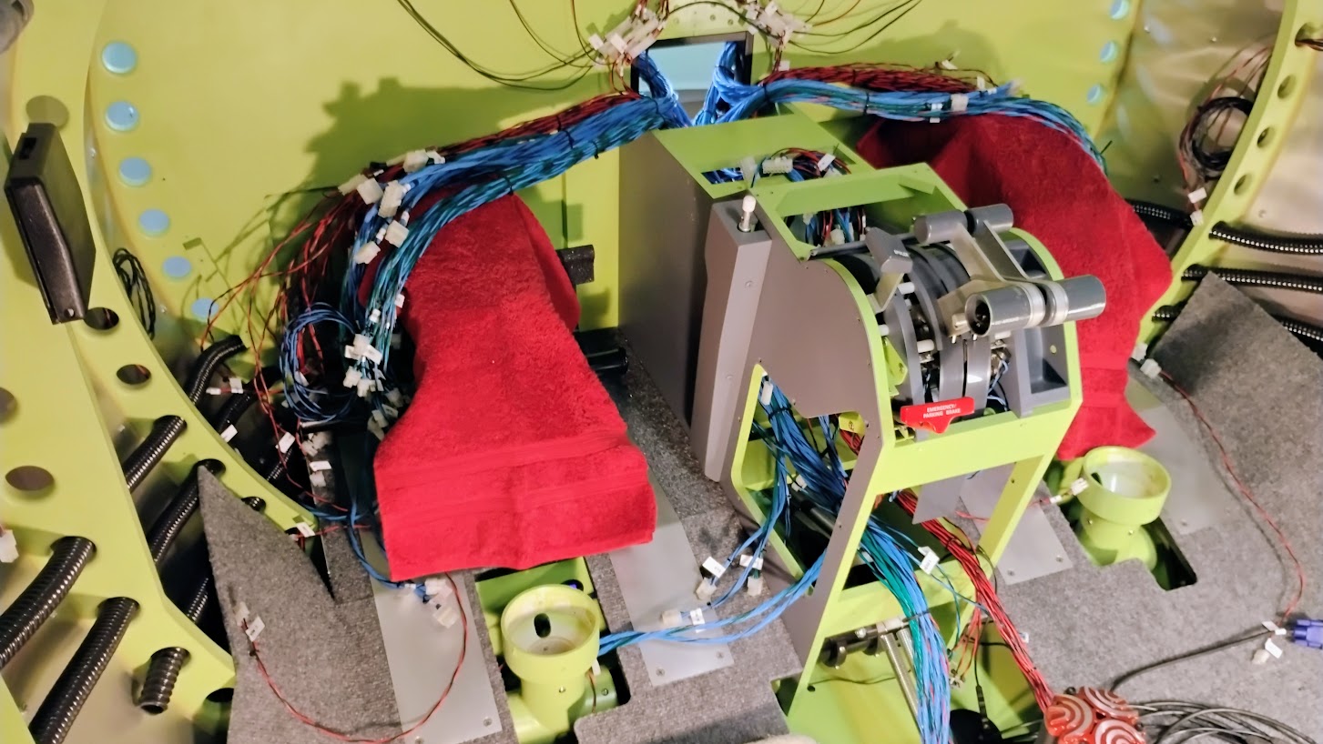
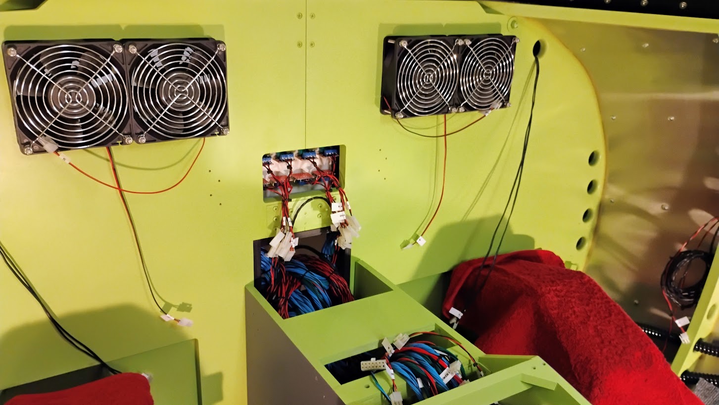
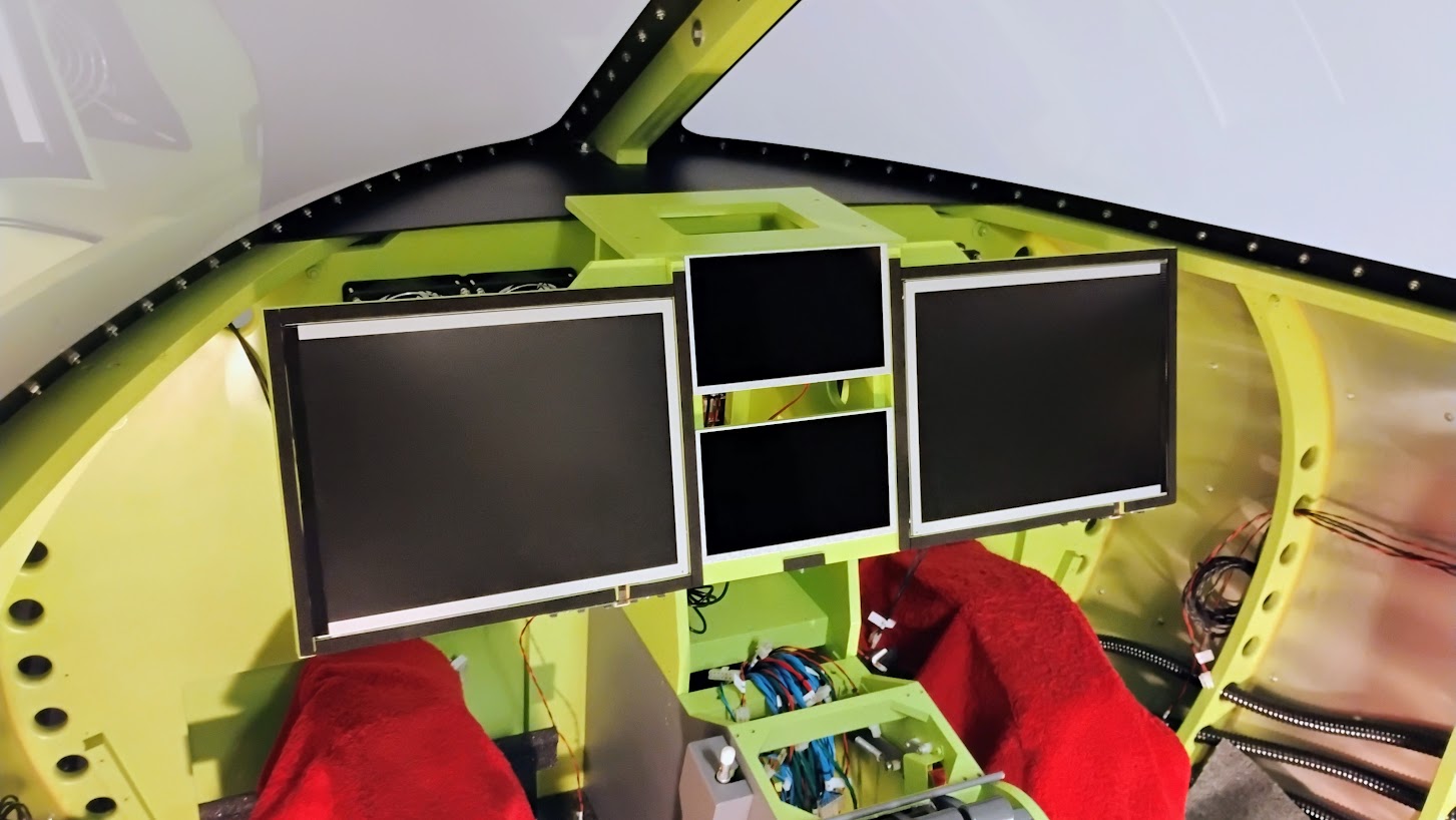
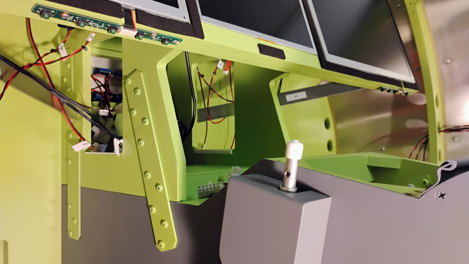
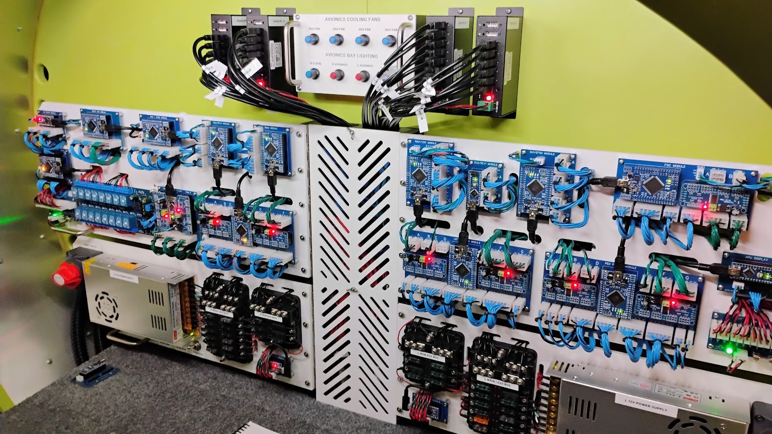
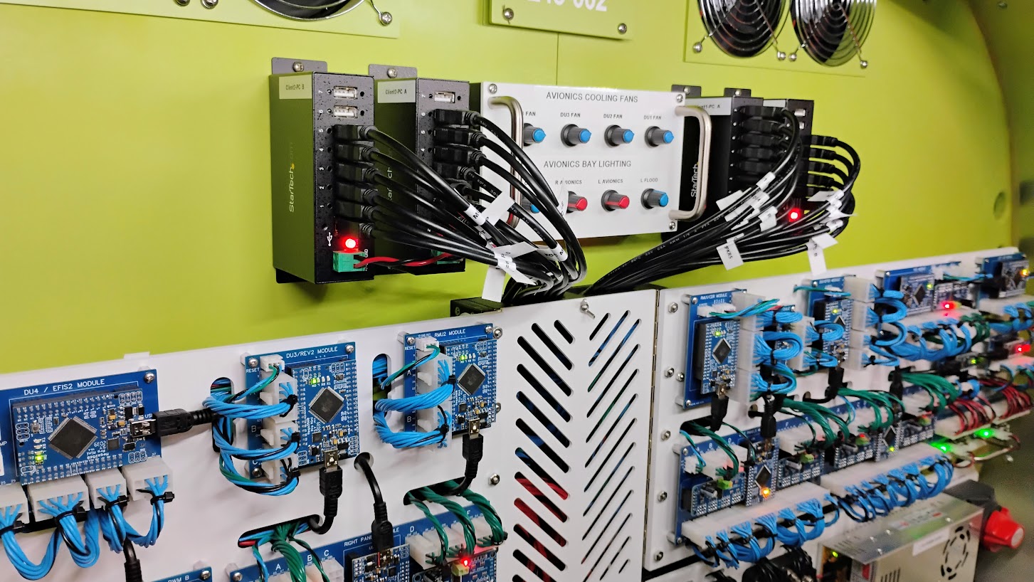
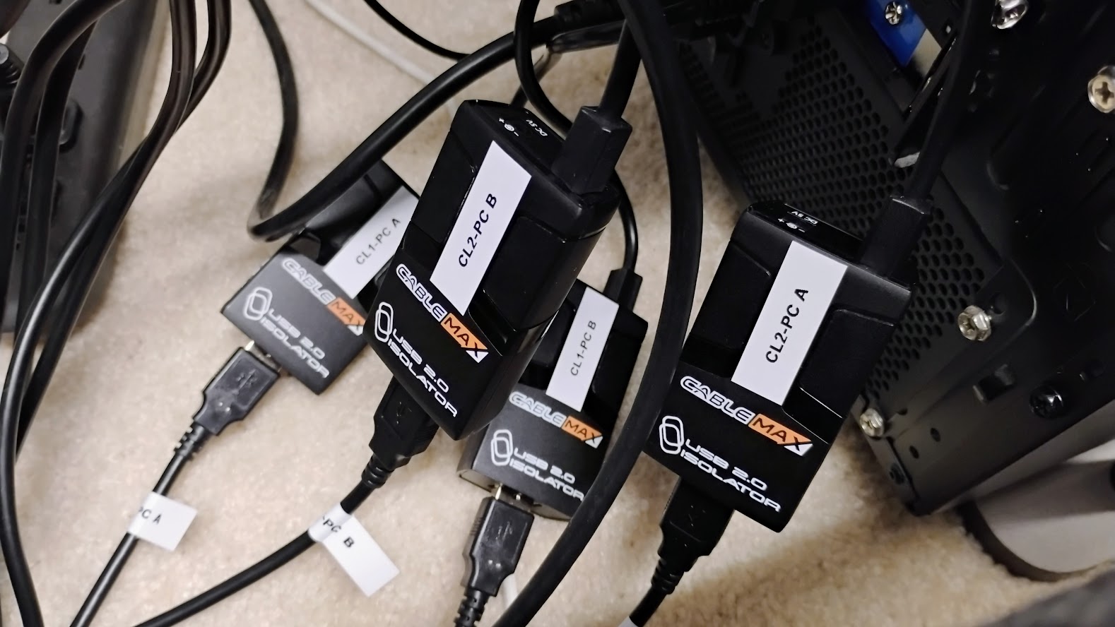
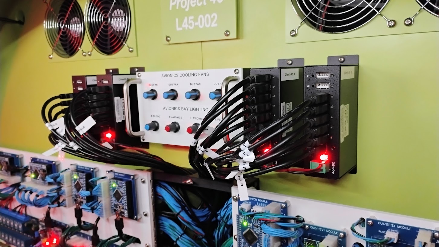
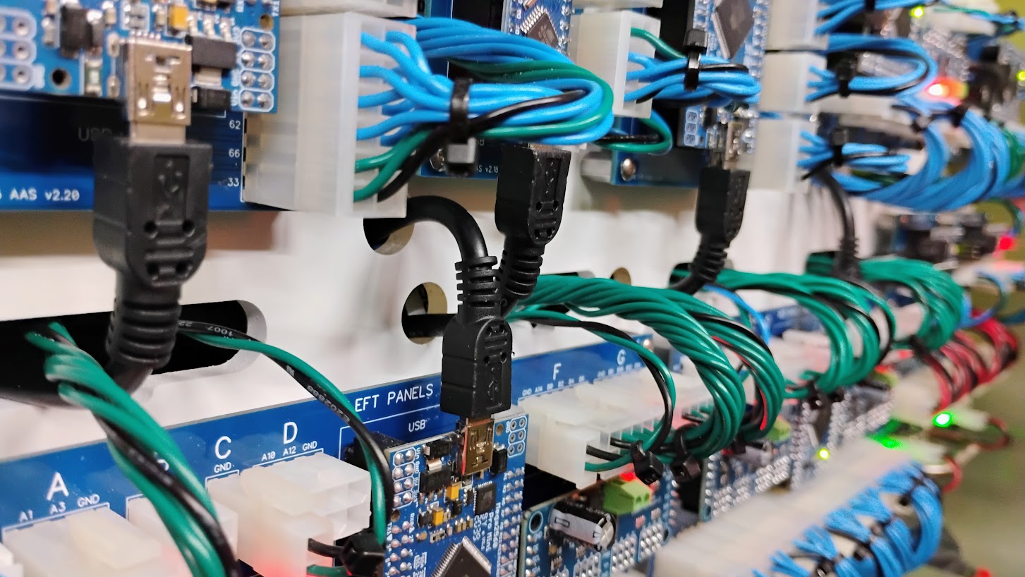
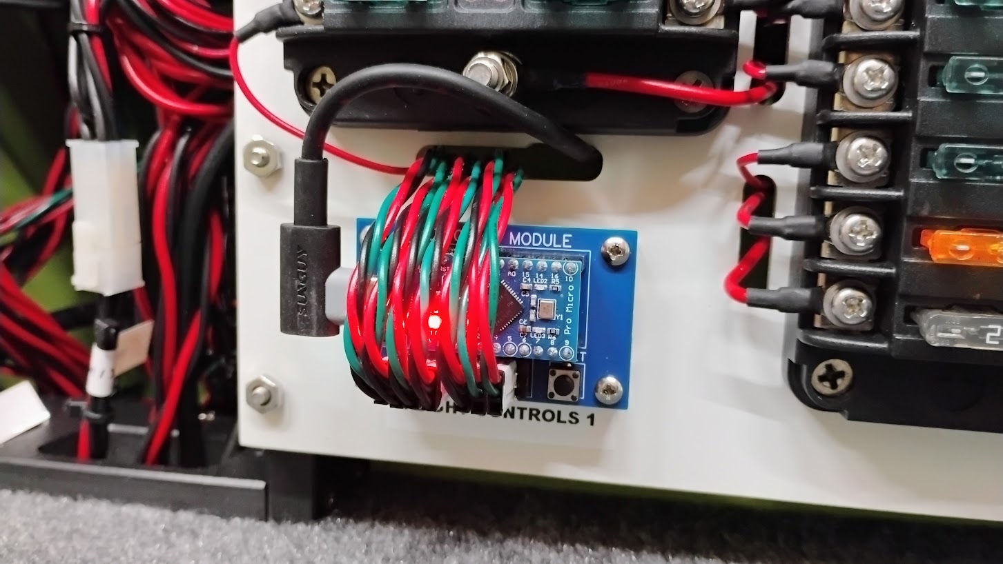
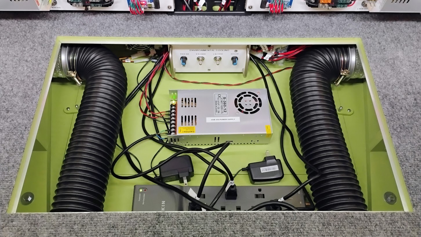
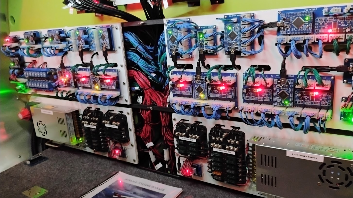
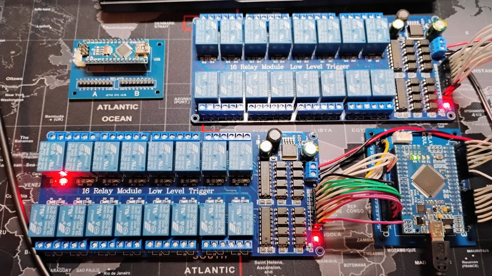
Very nice! If mine is half as neat I will be happy.😃 What wire guage did you use? Regarding fault finding, I have created a Line and Pin Allocation Test device to check wiring is good and which pin on the plug is connected. It can check any of the Val-U-Lok plugs with user selectable GND pin. I will post more about it later. Very nice! If mine is half as neat I will be happy.😃 What wire guage did you use? Regarding fault finding, I have created a Line and Pin Allocation Test device to check wiring is good and which pin on the plug is connected. It can check any of the Val-U-Lok plugs with user selectable GND pin. I will post more about it later. Thanks guys! It has been a lot of work and what you don't see is how many times I had to rework something to straighten things out one way or the other. To answer your question Will, I use 22 gauge "stranded" wire for almost everything except for the higher voltage items. Smaller 24 gauge wire can certainly handle the low volt digital signals but the issue I found is the connections feel weak. With all the tugging and pulling of the wire bundles, it would be really easy to pull something loose. Also make sure to use "stranded" wires rather than "solid". Here are a couple more photos of the recent progress starting with the TQ Pedestal installed. It took some time routing all the bundles in the directions they needed to go. Once sorted, I grouped them with a couple sets of zip ties. I then had to tuck all the wires back into the TQ Pedestal to clear the top area for the MIP Tower mounting. It's all part of the assembly process. Here is the MIP Tower and MIP Backer with the monitors is installed. Looking pretty cool! While I was securing the brackets I thought I would take a photo of an angle we don't ever see. This substructure is very strong and secure. There is very little movement once everything is screwed down. If you look closely, you can see the left mounting bracket that secures the MIP Tower to the F3 bulkhead. I know I'm getting a little outside of the Avionics Bay so this will probably be the last update on this thread until there is new and relevant information on the other side of the F3 bulkhead. 🙂 Comments and questions welcome! Thanks guys! It has been a lot of work and what you don't see is how many times I had to rework something to straighten things out one way or the other. To answer your question Will, I use 22 gauge "stranded" wire for almost everything except for the higher voltage items. Smaller 24 gauge wire can certainly handle the low volt digital signals but the issue I found is the connections feel weak. With all the tugging and pulling of the wire bundles, it would be really easy to pull something loose. Also make sure to use "stranded" wires rather than "solid". Here are a couple more photos of the recent progress starting with the TQ Pedestal installed. It took some time routing all the bundles in the directions they needed to go. Once sorted, I grouped them with a couple sets of zip ties. I then had to tuck all the wires back into the TQ Pedestal to clear the top area for the MIP Tower mounting. It's all part of the assembly process. Here is the MIP Tower and MIP Backer with the monitors is installed. Looking pretty cool! While I was securing the brackets I thought I would take a photo of an angle we don't ever see. This substructure is very strong and secure. There is very little movement once everything is screwed down. If you look closely, you can see the left mounting bracket that secures the MIP Tower to the F3 bulkhead. I know I'm getting a little outside of the Avionics Bay so this will probably be the last update on this thread until there is new and relevant information on the other side of the F3 bulkhead. 🙂 Comments and questions welcome! Hey guys, I have been moving forward "meticulously" with getting the sim back up and running. This past few weeks I have been working on the USB cables, powered hubs and USB isolators. Here is an overview of what things look like today. There are a couple ways to go about connecting USB cables to all the MANY Arduinos and other things that require a USB connection. There are several things to consider: If not careful and you haphazardly try to make things work, you might start off with success connecting one Arduino and maybe a second Arduino, but things can quickly go sideways if there is a kink in your armor, meaning lost connections, USBs dropping offline, EMI sneaking into the lines, etc.. You could purchase a couple "Amazon" USB powered ports which most of the time work fine, especially if your setup uses USB cables under five feet long. Or you could go more in the direction of what DonnyRay is doing which is to try to eliminate all potential issues related to USB power, reliability, and reducing EMI to near nothing. I opted for the latter. The reason why it's a good idea to use higher quality components is to reduce the things that can go wrong. We will have no less than 25 USB components, (mostly Arduinos) operating all at the same time. Things will go wrong or not work properly and when they do, we don't need to wonder if it's hardware related. I use Startech 7 port USB 2.0 powered hubs. Four of them which gives me 28 USB sockets to use. Two are connected to Client1-PC and two are connected to Client2-PC. These Startech powered hubs are industrial grade and made to just WORK. New they are around $120 each. But you can find them used or "open box" for around $35 each which is what I did. Here I have 24 USB sockets in use, most of them running to the Arduinos in the Avionics Bay. The other thing that DonnyRay and I recommend is using USB isolators. We recommend using the USB 2.0 Isolator by CableMAX. They are actually a little on the expensive side at $60 each but well worth the piece of mind they provide. They will protect your computer from power surges and also protect against EMI running up and down your cables. They are easy to install being that they are an inline isolator, see photo. Last but not least, make sure you use shielded USB 2.0 cables. (The Arduinos we use only require 2.o USB speeds) Shielded USB cables run about the same in cost, maybe a little more but we need all USB cables, where possible, to be shielded. Generally, a way to tell a USB cable is shielded is it's thicker. Also check the product description when purchasing them, key word, "shielded". In my case, I have four 10 foot long shielded USB cables running from the USB isolators connected to the USBs of Client1-PC and Client2-PC. These four USB cables run to the four Startech powered hubs. Because I have the Startech USB hubs mounted in the Avionics Bay right above the pull out panels, I only need three foot long USB cables from the hubs to the Arduinos on the pull out panels. For the Flight Control modules, we have a couple options. The Leo Bodnar BU0836A cards are tested and proven, you can't go wrong with them! But I am opting to try the Arduino Micro which is the smaller version of the Arduino Leonardo card. These cards are recognized and act just like a gaming joystick. Setup for them is fairly straight forward. Here is the FLT CTL 1 module hooked up and ready to go! Last but not least, the powered hubs require an external power source rated between 7 and 24 volts. This power supply needs to be separate from the "aircraft systems" power supplies which use a left 12v power supply and a right 12v power supply. Think of it like this, the third 12v power supply is for supplemental power to the USB devices which are extensions of the computers. These extensions are things like the many Arduinos, speaker systems, etc. We would not ever want to cut power to this third 12v power supply even when the cockpit is in a cold and dark state. Here is a photo of where my third 12v power supply is housed, under the Avionics Bay floor hatch. The sim is now just about ready to get fired up for trouble shooting efforts. Here we have all the Arduinos flashed with their most up to date hex files and connected to USB cables. Meticulous detail comes to mind when you look at this. It looks tidy and neat but in my opinion, it's absolutely necessary in order to reduce the "Gremlins". Here is an interesting shot. I knew there was going to be a boat load of wires and cables running through the center wire management area. I can barely get me hand through this area now, especially the top section. One last area I am working on, the Relay modules. I am starting with some "bench testing" to educate myself what is considered normal operation. I put together a couple simple relay test programs that cycle through each relay one at a time. The initial plan was to use a single 16 channel relay card. But last year it became clear that we will need a second 16 channel relay card in order to add additional functionality, like load shedding capabilities. Here is a snap shot of the two 16 channel relay cards hooked to an Arduino Mega Pro Mini. (The Arduino Nano relay module is in the photo but not connected.) For clarification, the Mega will replace the Nano. Another update soon! Hey guys, I have been moving forward "meticulously" with getting the sim back up and running. This past few weeks I have been working on the USB cables, powered hubs and USB isolators. Here is an overview of what things look like today. There are a couple ways to go about connecting USB cables to all the MANY Arduinos and other things that require a USB connection. There are several things to consider: If not careful and you haphazardly try to make things work, you might start off with success connecting one Arduino and maybe a second Arduino, but things can quickly go sideways if there is a kink in your armor, meaning lost connections, USBs dropping offline, EMI sneaking into the lines, etc.. You could purchase a couple "Amazon" USB powered ports which most of the time work fine, especially if your setup uses USB cables under five feet long. Or you could go more in the direction of what DonnyRay is doing which is to try to eliminate all potential issues related to USB power, reliability, and reducing EMI to near nothing. I opted for the latter. The reason why it's a good idea to use higher quality components is to reduce the things that can go wrong. We will have no less than 25 USB components, (mostly Arduinos) operating all at the same time. Things will go wrong or not work properly and when they do, we don't need to wonder if it's hardware related. I use Startech 7 port USB 2.0 powered hubs. Four of them which gives me 28 USB sockets to use. Two are connected to Client1-PC and two are connected to Client2-PC. These Startech powered hubs are industrial grade and made to just WORK. New they are around $120 each. But you can find them used or "open box" for around $35 each which is what I did. Here I have 24 USB sockets in use, most of them running to the Arduinos in the Avionics Bay. The other thing that DonnyRay and I recommend is using USB isolators. We recommend using the USB 2.0 Isolator by CableMAX. They are actually a little on the expensive side at $60 each but well worth the piece of mind they provide. They will protect your computer from power surges and also protect against EMI running up and down your cables. They are easy to install being that they are an inline isolator, see photo. Last but not least, make sure you use shielded USB 2.0 cables. (The Arduinos we use only require 2.o USB speeds) Shielded USB cables run about the same in cost, maybe a little more but we need all USB cables, where possible, to be shielded. Generally, a way to tell a USB cable is shielded is it's thicker. Also check the product description when purchasing them, key word, "shielded". In my case, I have four 10 foot long shielded USB cables running from the USB isolators connected to the USBs of Client1-PC and Client2-PC. These four USB cables run to the four Startech powered hubs. Because I have the Startech USB hubs mounted in the Avionics Bay right above the pull out panels, I only need three foot long USB cables from the hubs to the Arduinos on the pull out panels. For the Flight Control modules, we have a couple options. The Leo Bodnar BU0836A cards are tested and proven, you can't go wrong with them! But I am opting to try the Arduino Micro which is the smaller version of the Arduino Leonardo card. These cards are recognized and act just like a gaming joystick. Setup for them is fairly straight forward. Here is the FLT CTL 1 module hooked up and ready to go! Last but not least, the powered hubs require an external power source rated between 7 and 24 volts. This power supply needs to be separate from the "aircraft systems" power supplies which use a left 12v power supply and a right 12v power supply. Think of it like this, the third 12v power supply is for supplemental power to the USB devices which are extensions of the computers. These extensions are things like the many Arduinos, speaker systems, etc. We would not ever want to cut power to this third 12v power supply even when the cockpit is in a cold and dark state. Here is a photo of where my third 12v power supply is housed, under the Avionics Bay floor hatch. The sim is now just about ready to get fired up for trouble shooting efforts. Here we have all the Arduinos flashed with their most up to date hex files and connected to USB cables. Meticulous detail comes to mind when you look at this. It looks tidy and neat but in my opinion, it's absolutely necessary in order to reduce the "Gremlins". Here is an interesting shot. I knew there was going to be a boat load of wires and cables running through the center wire management area. I can barely get me hand through this area now, especially the top section. One last area I am working on, the Relay modules. I am starting with some "bench testing" to educate myself what is considered normal operation. I put together a couple simple relay test programs that cycle through each relay one at a time. The initial plan was to use a single 16 channel relay card. But last year it became clear that we will need a second 16 channel relay card in order to add additional functionality, like load shedding capabilities. Here is a snap shot of the two 16 channel relay cards hooked to an Arduino Mega Pro Mini. (The Arduino Nano relay module is in the photo but not connected.) For clarification, the Mega will replace the Nano. Another update soon!Avionics Bay and Components v2.0
![]()

![]()
![]()

2017-10-10