


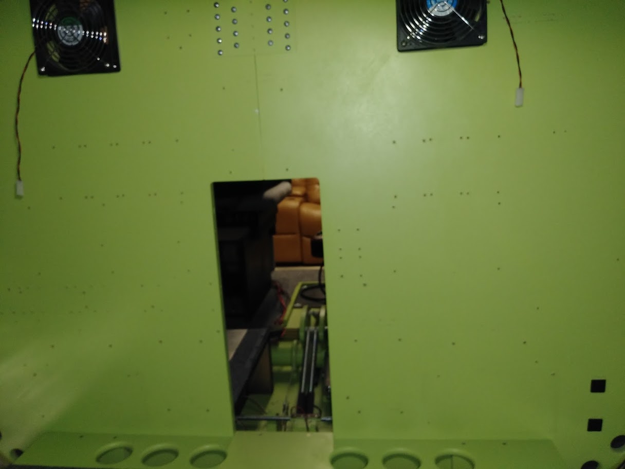
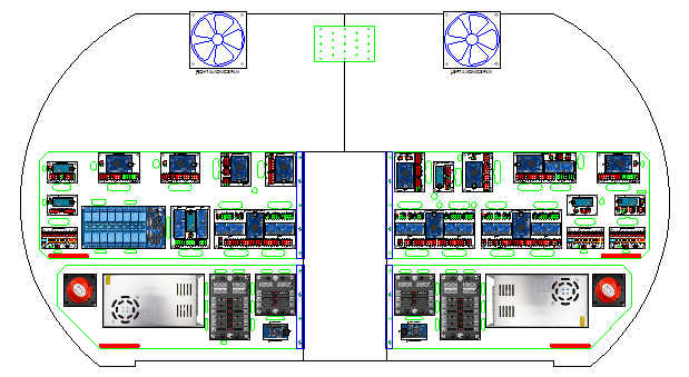
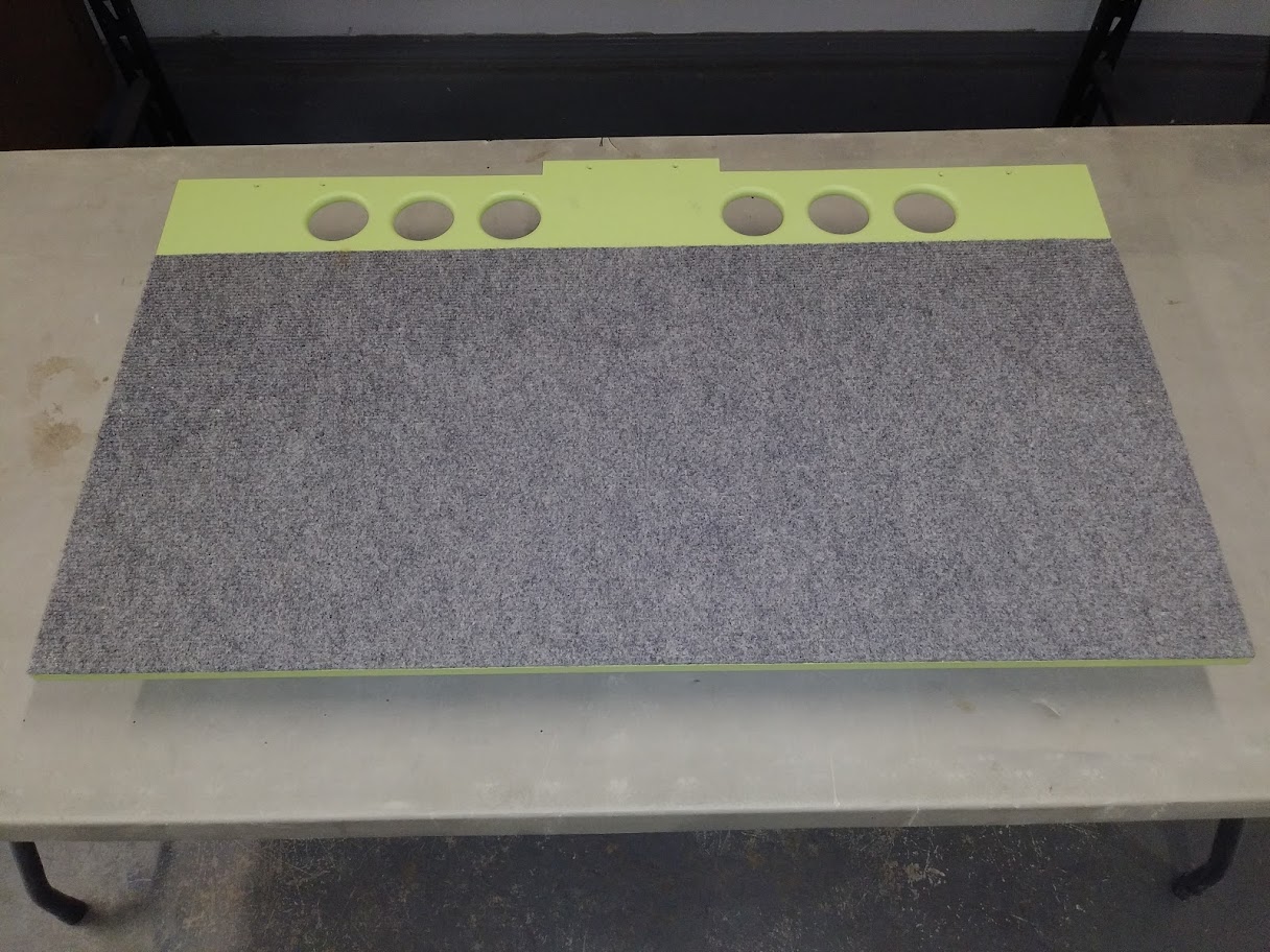
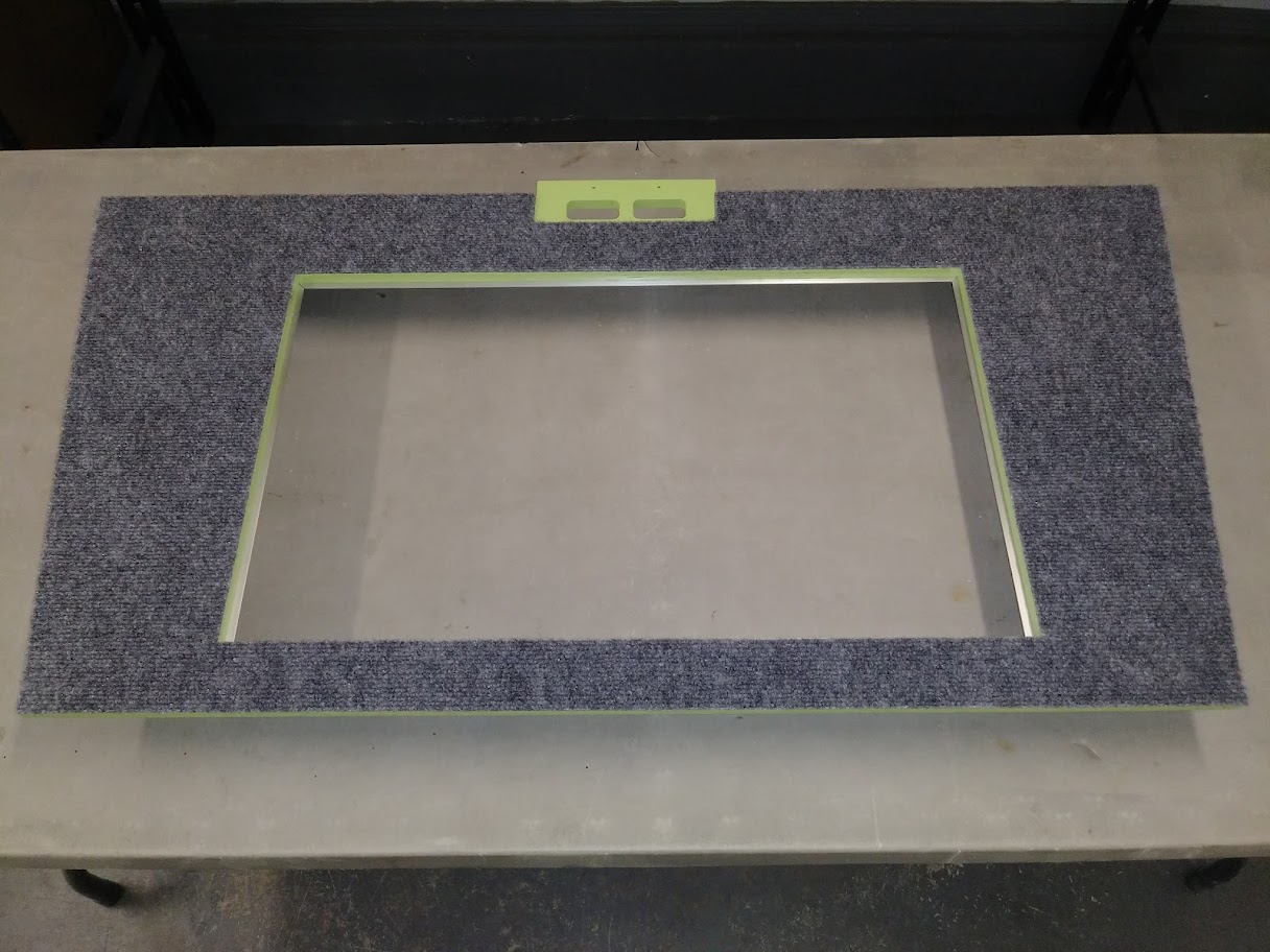
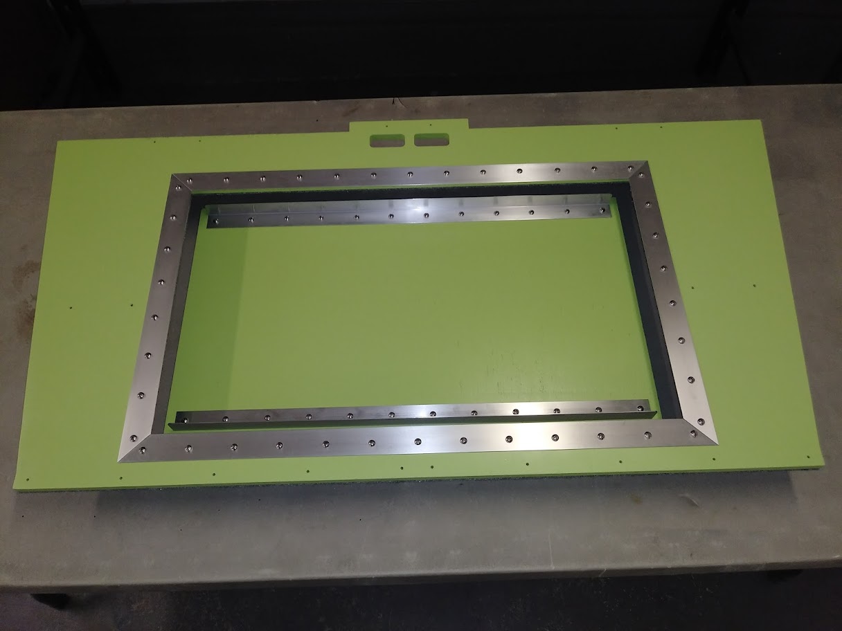
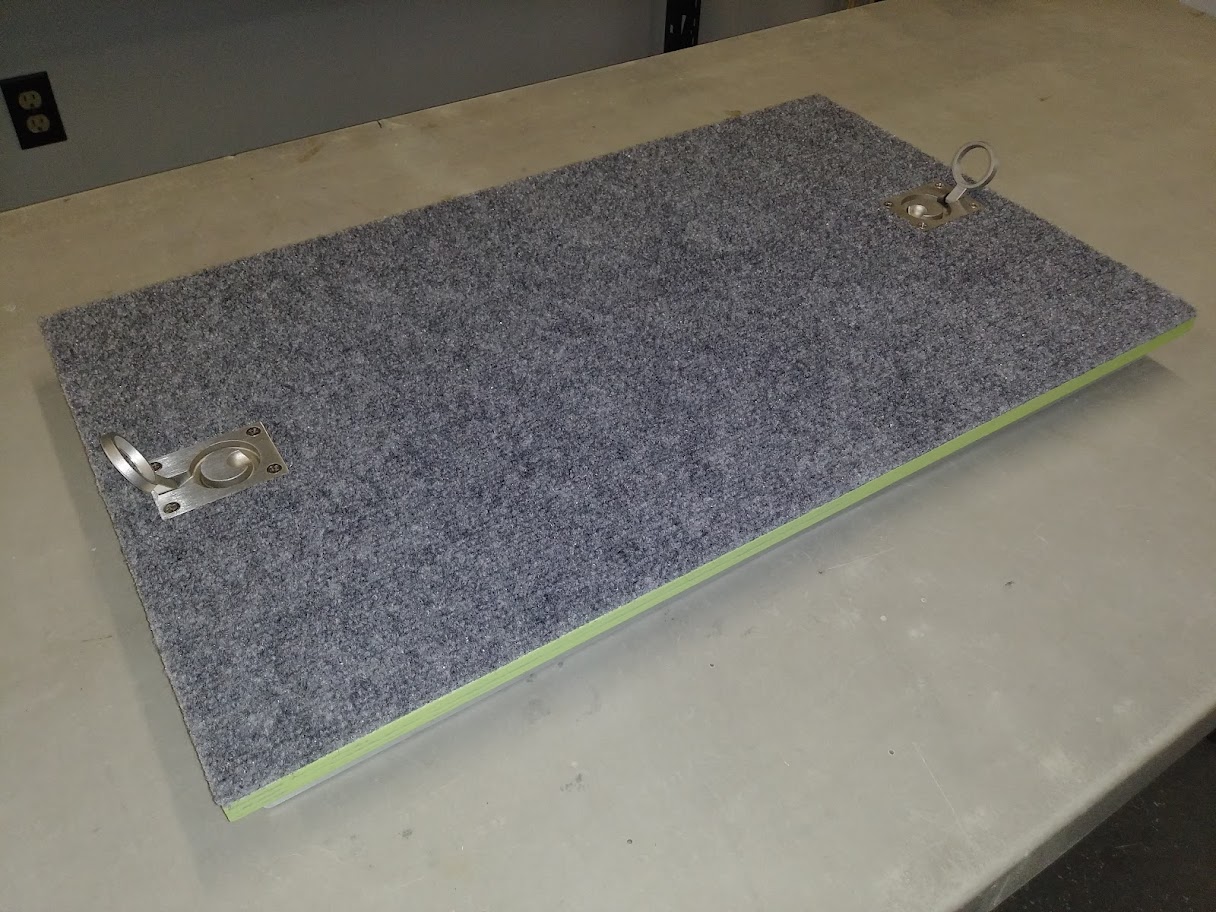
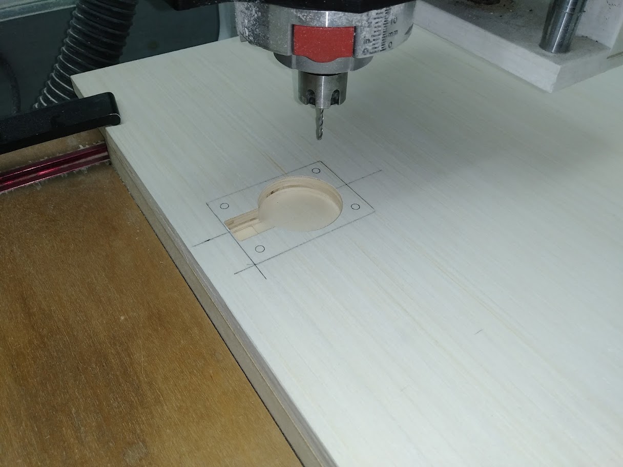
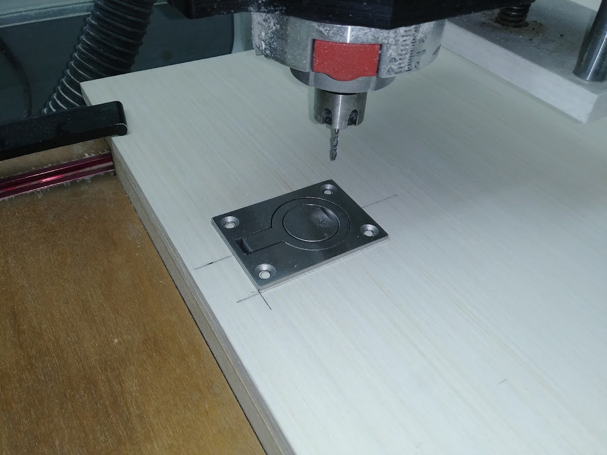
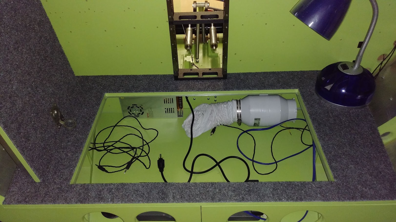
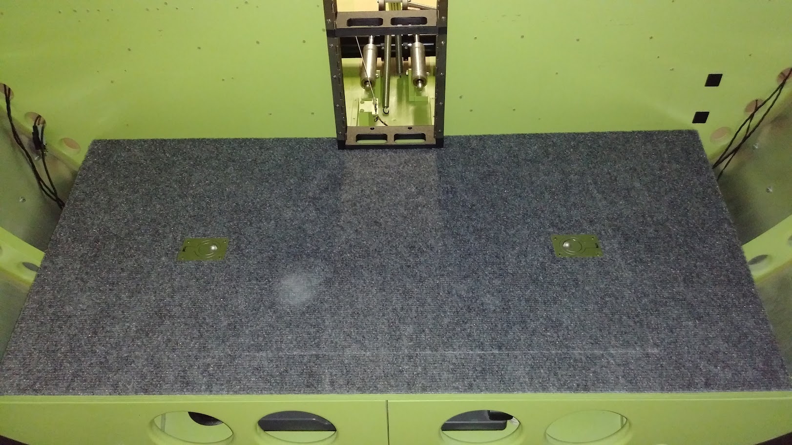
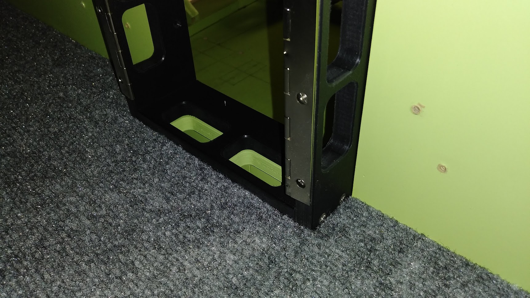
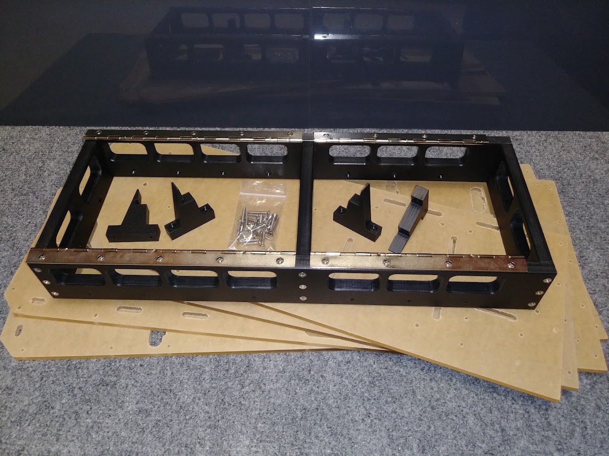
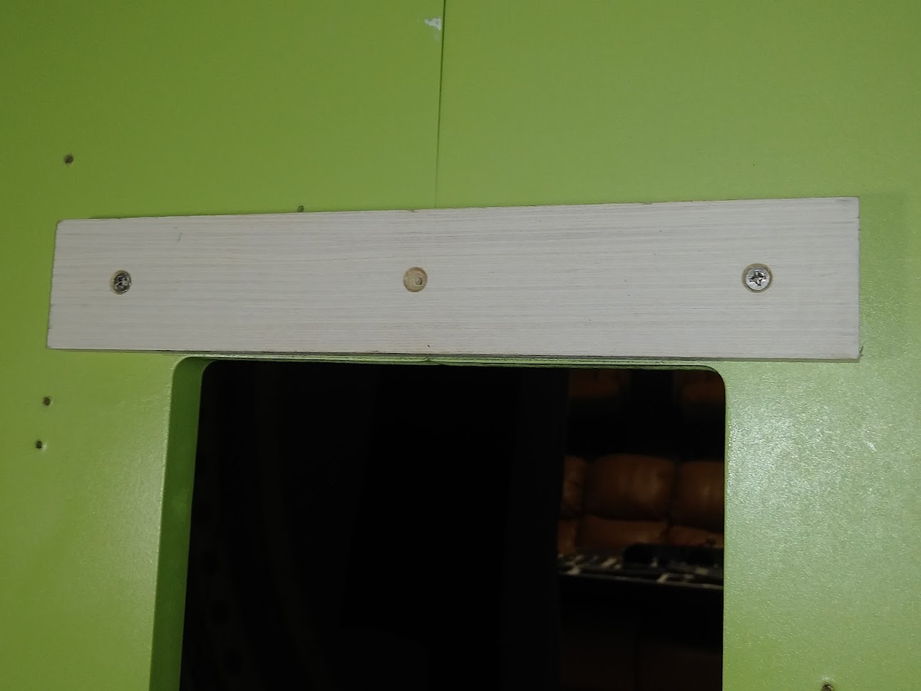
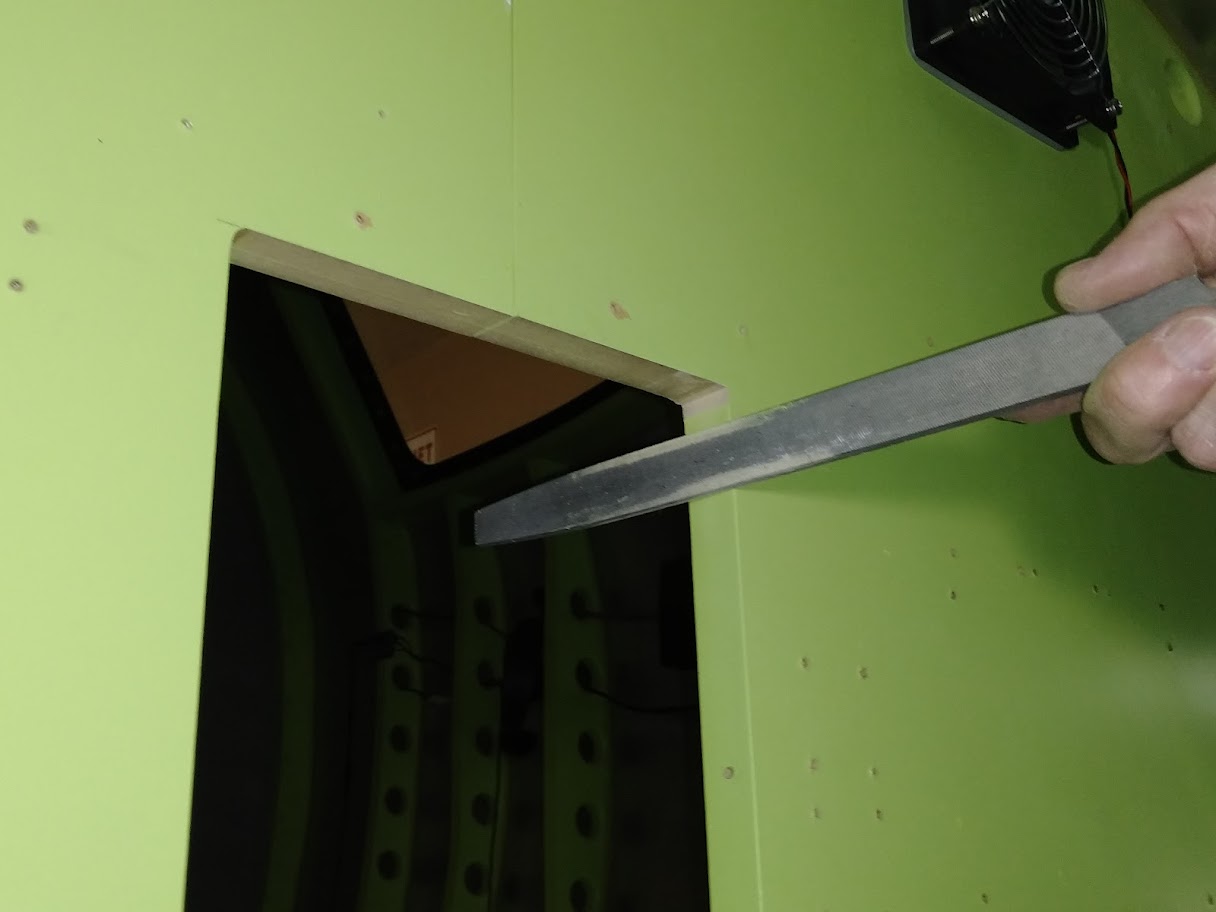
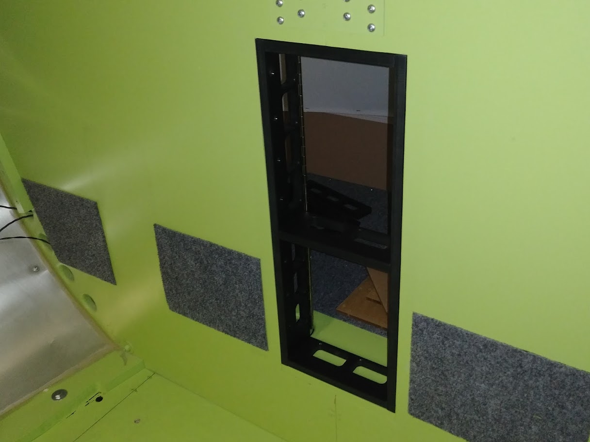
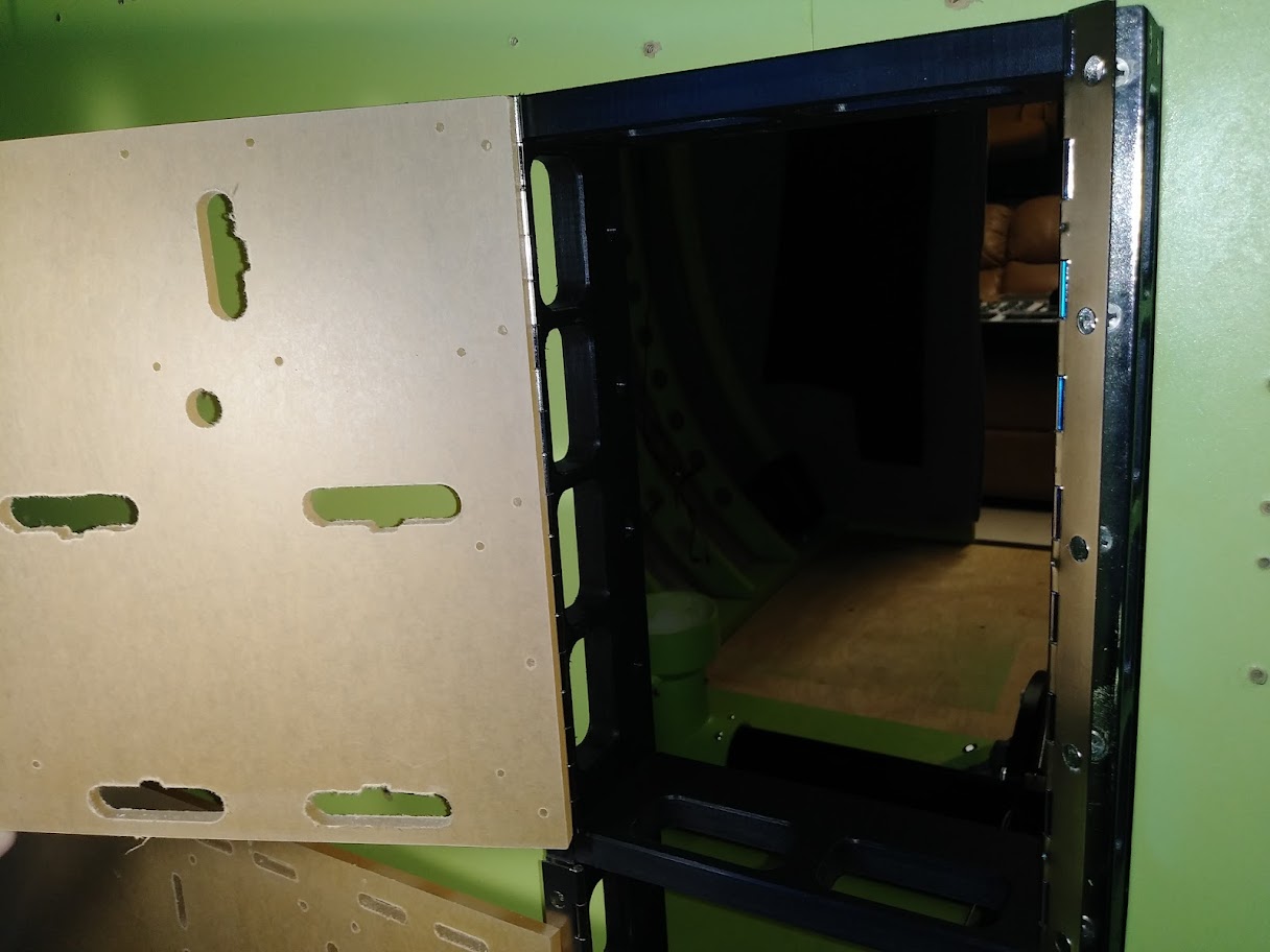
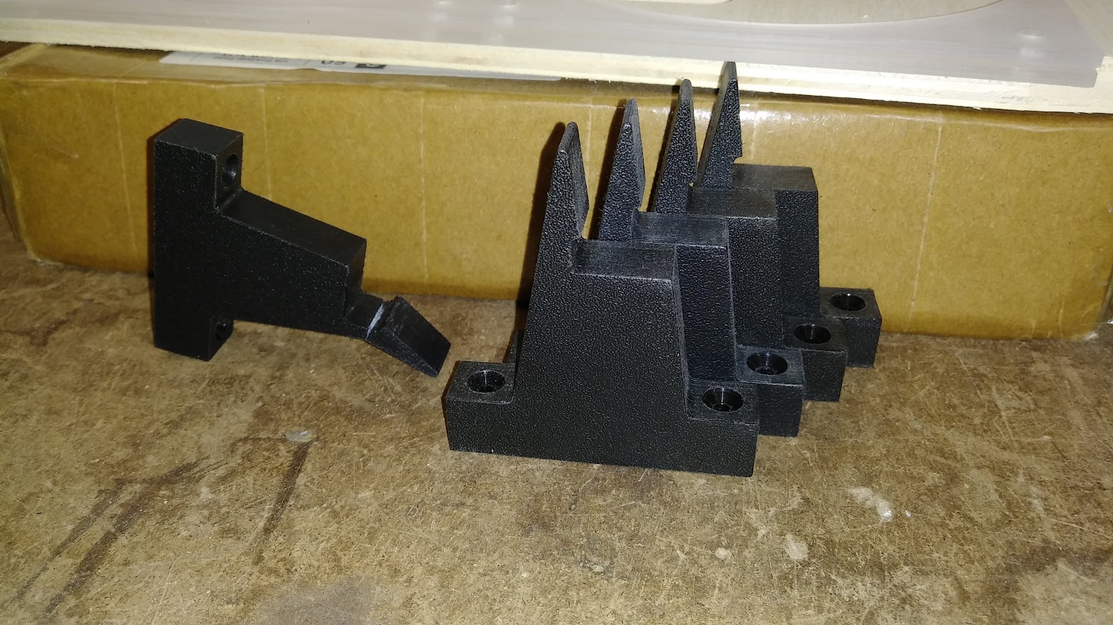
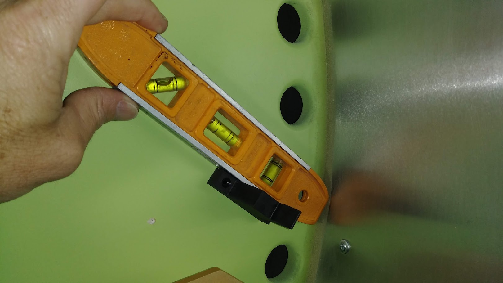
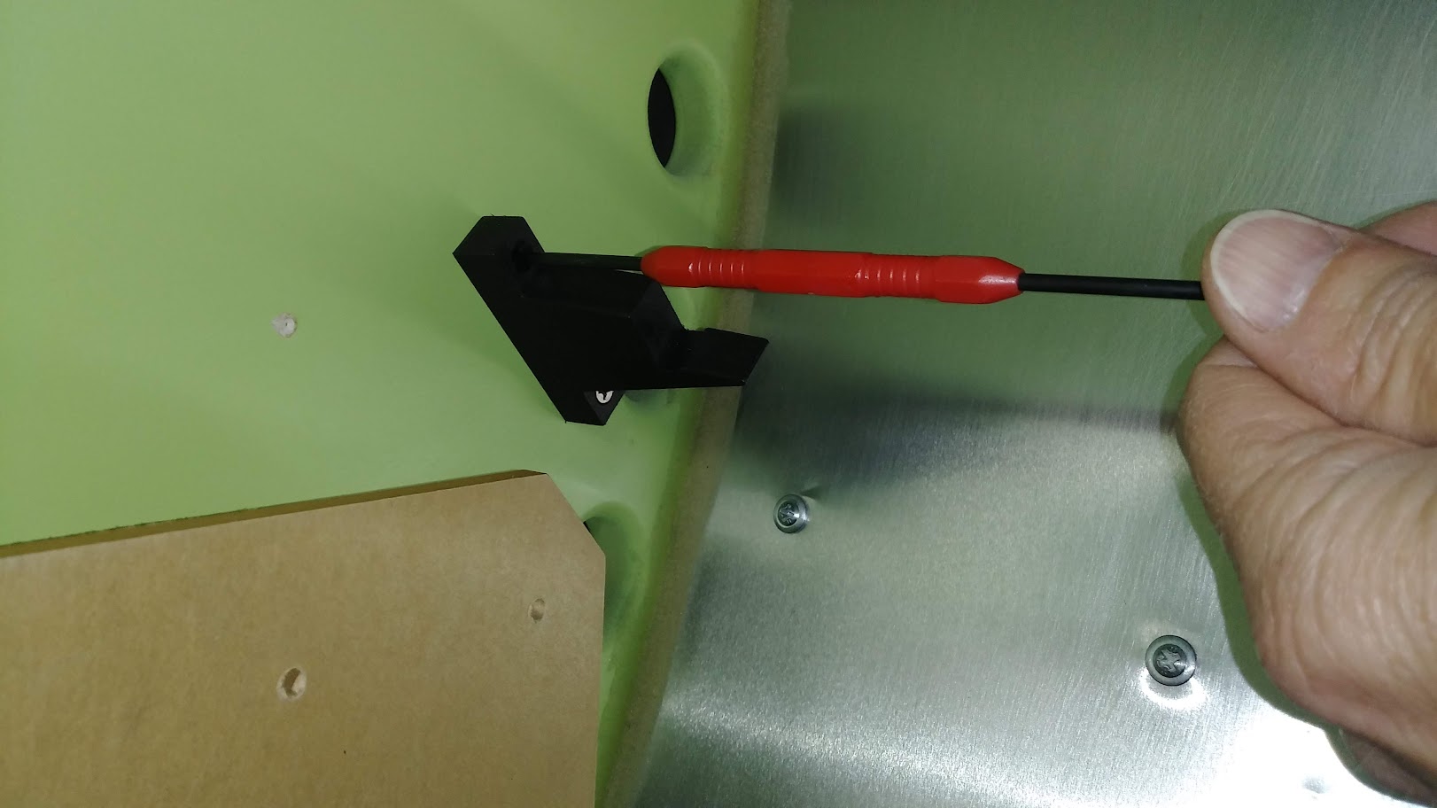
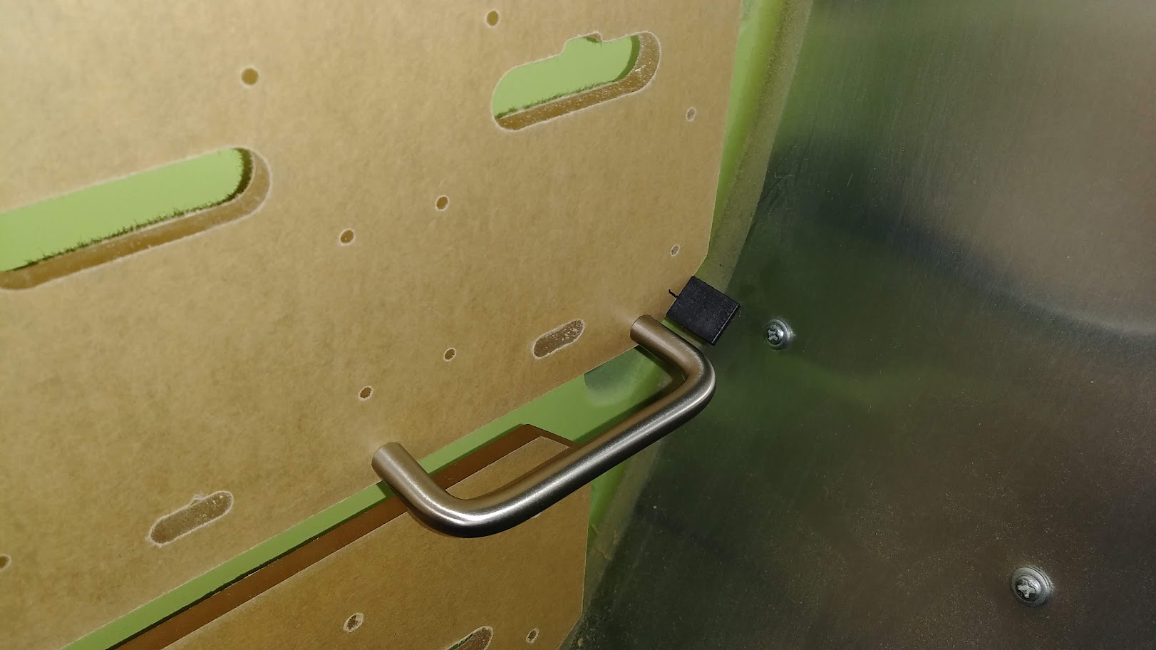
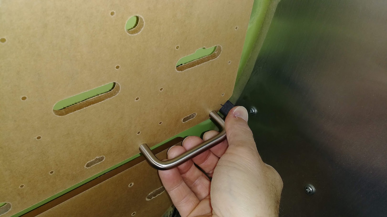
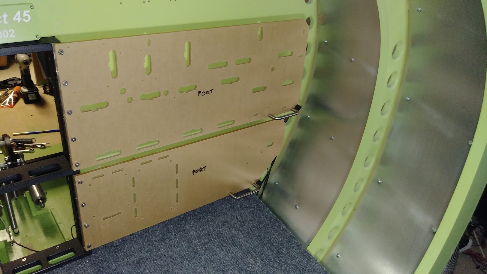
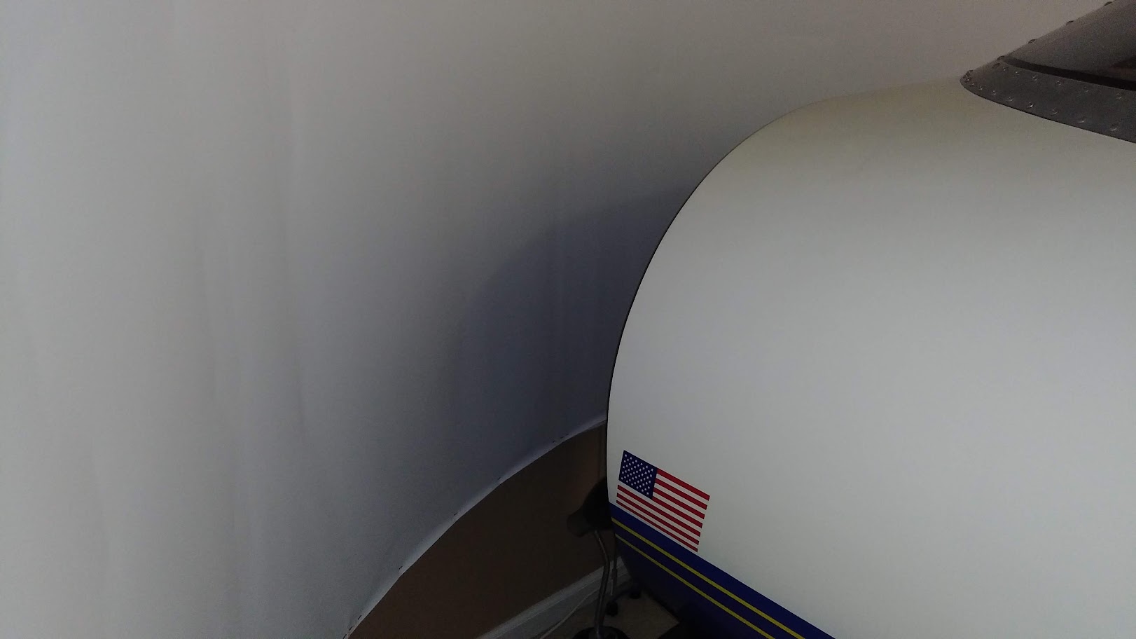
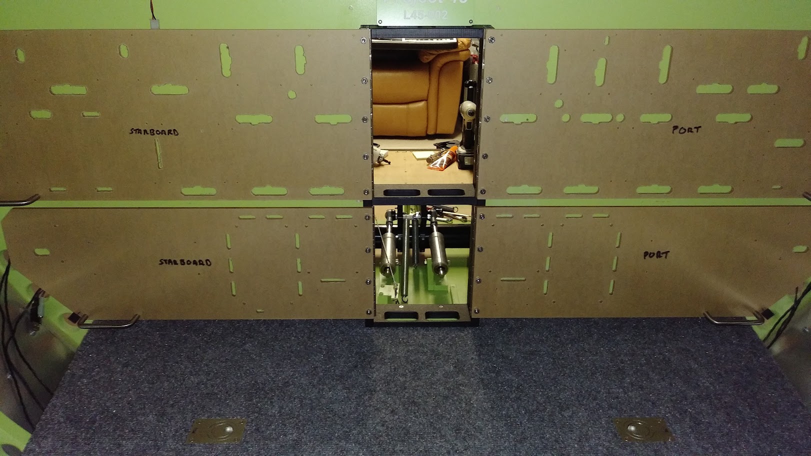
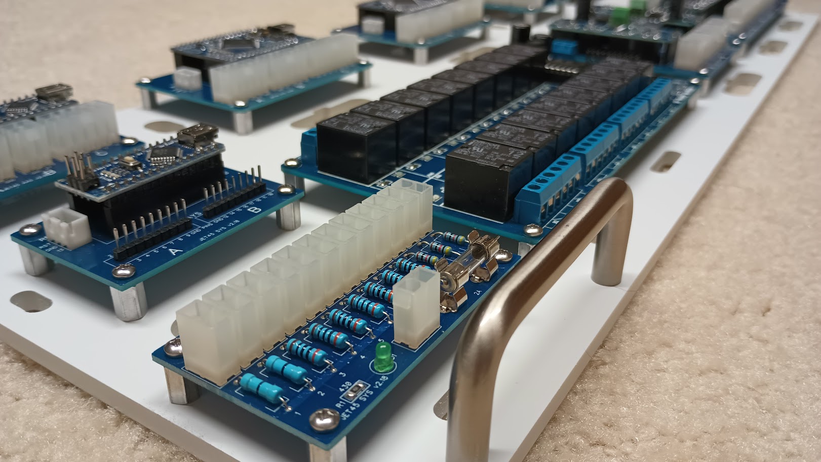
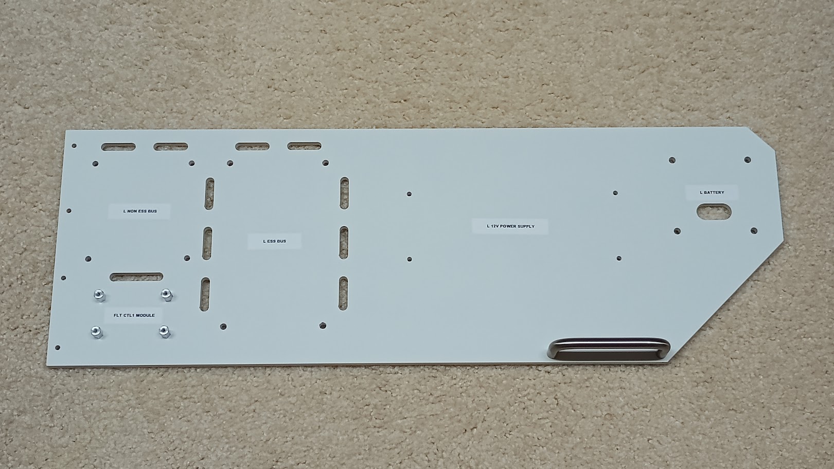
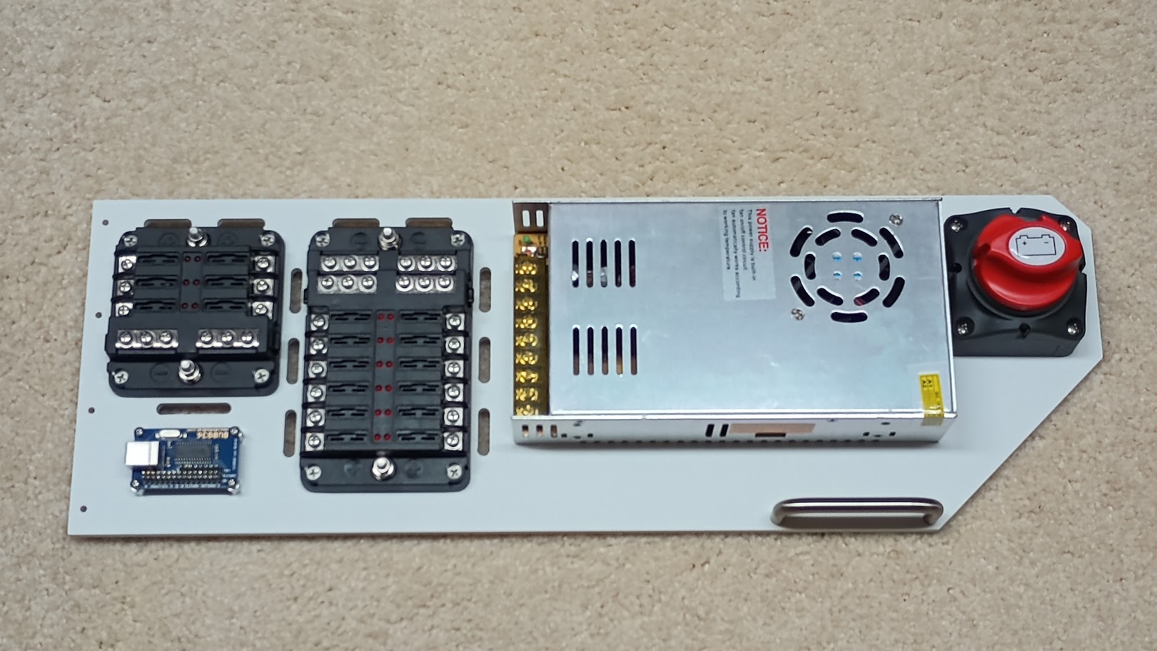
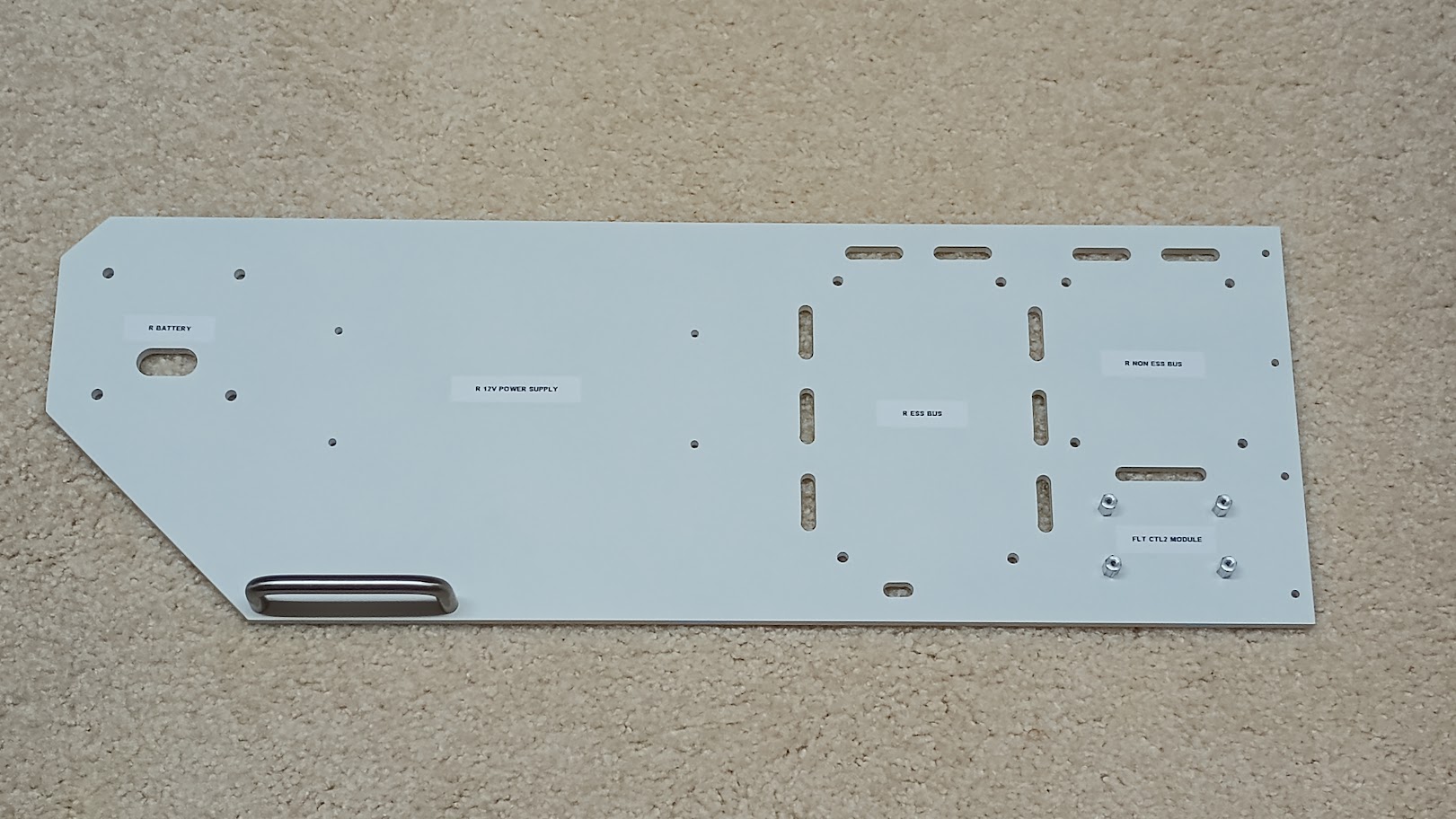
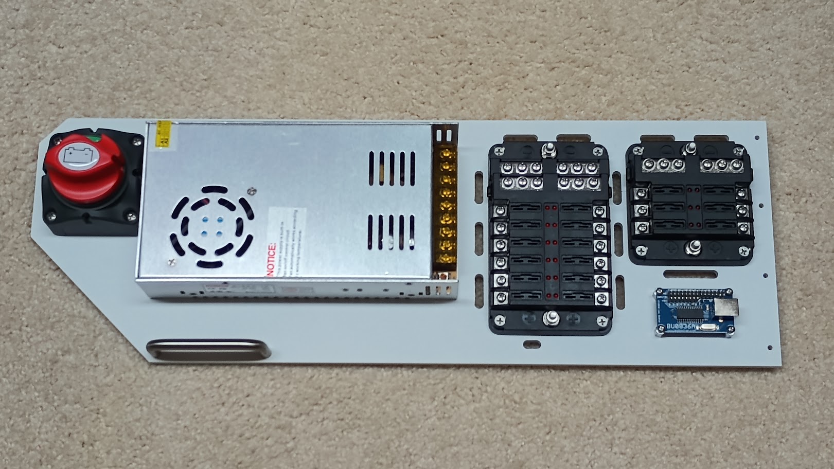
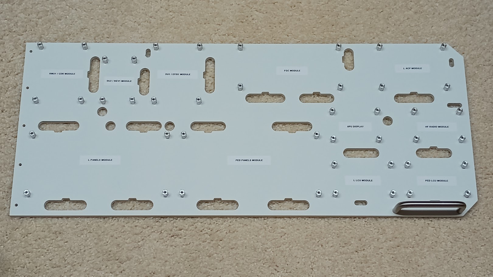
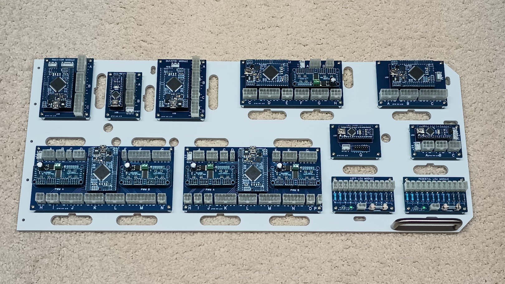
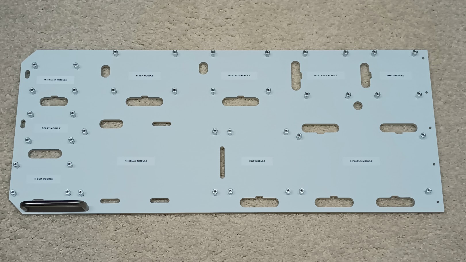
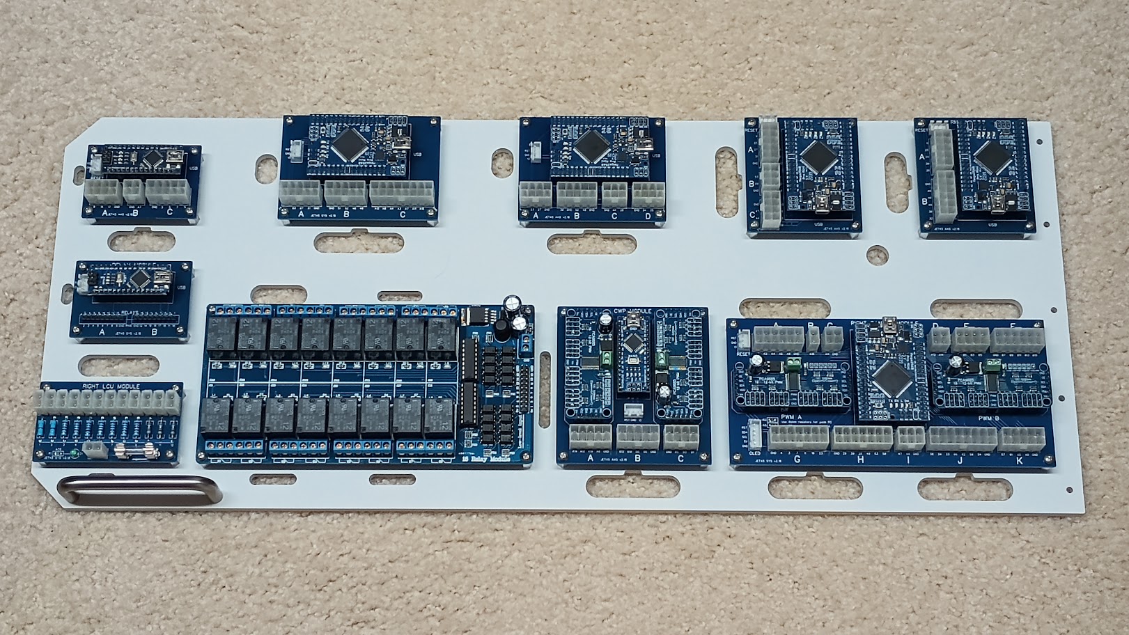
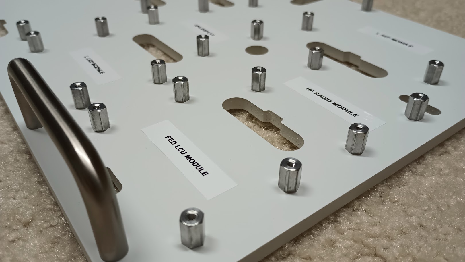
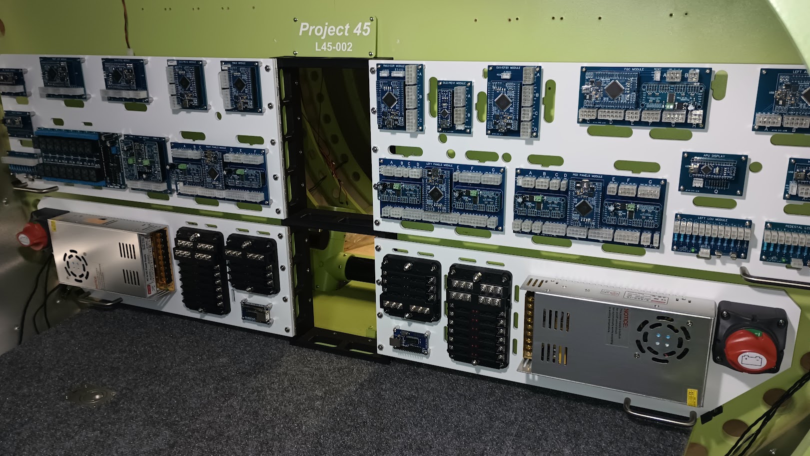
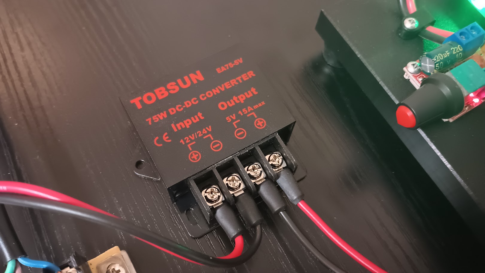
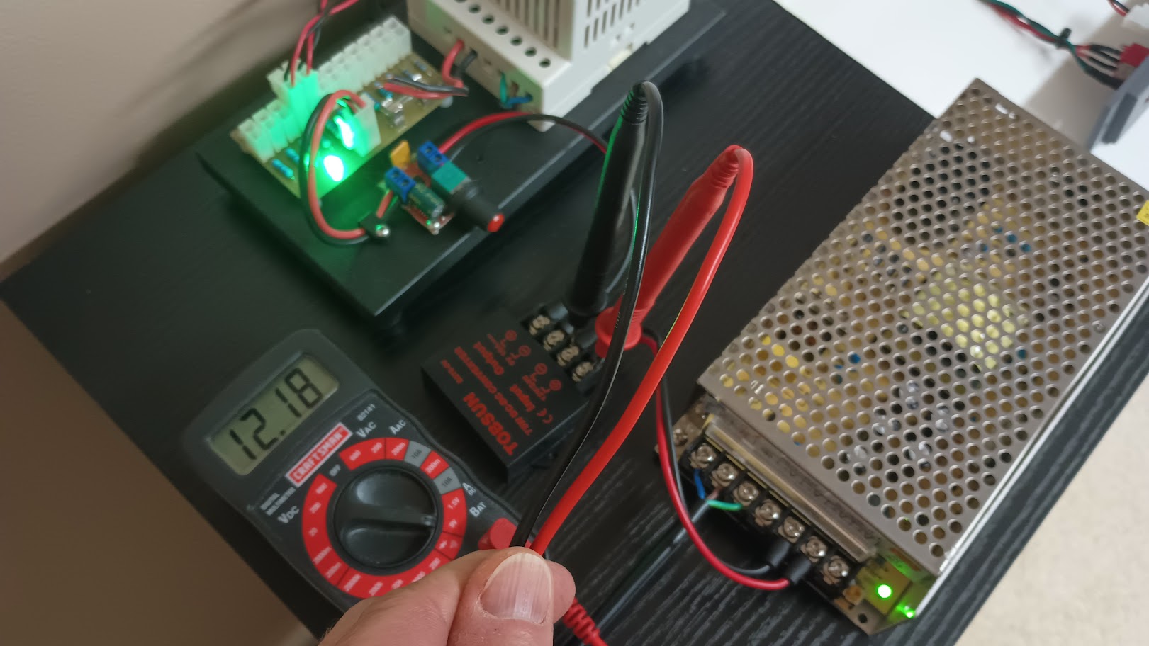
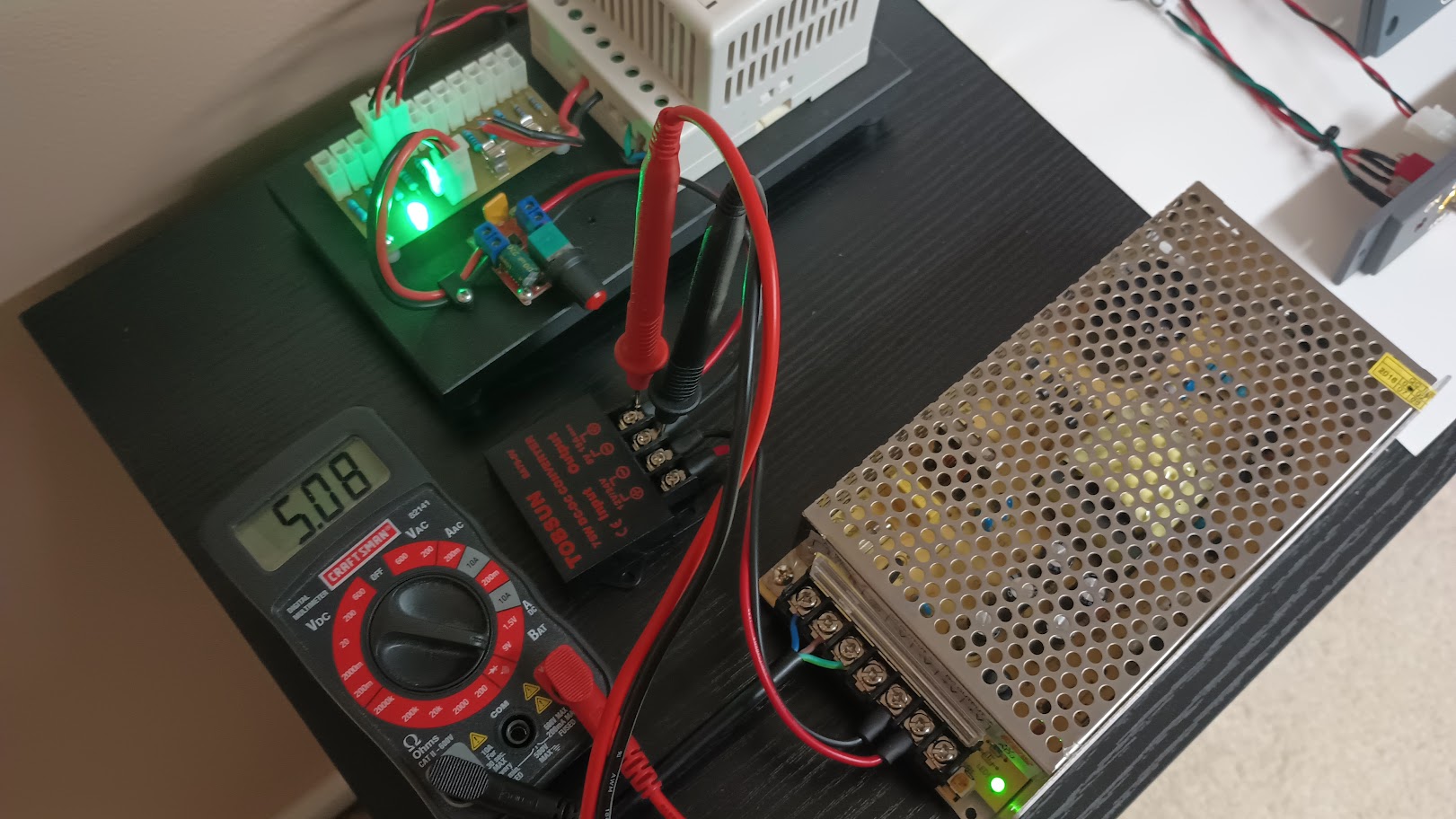
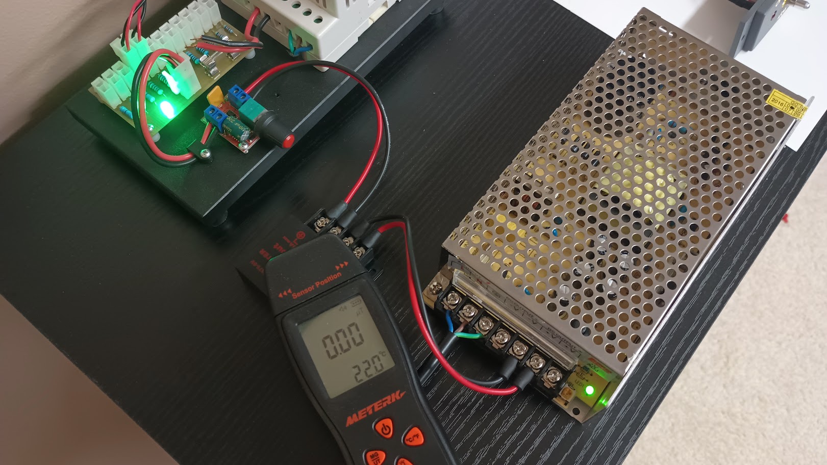
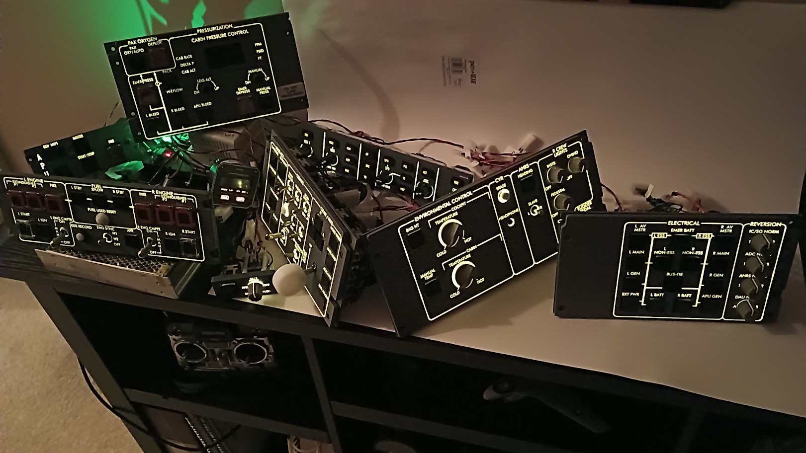
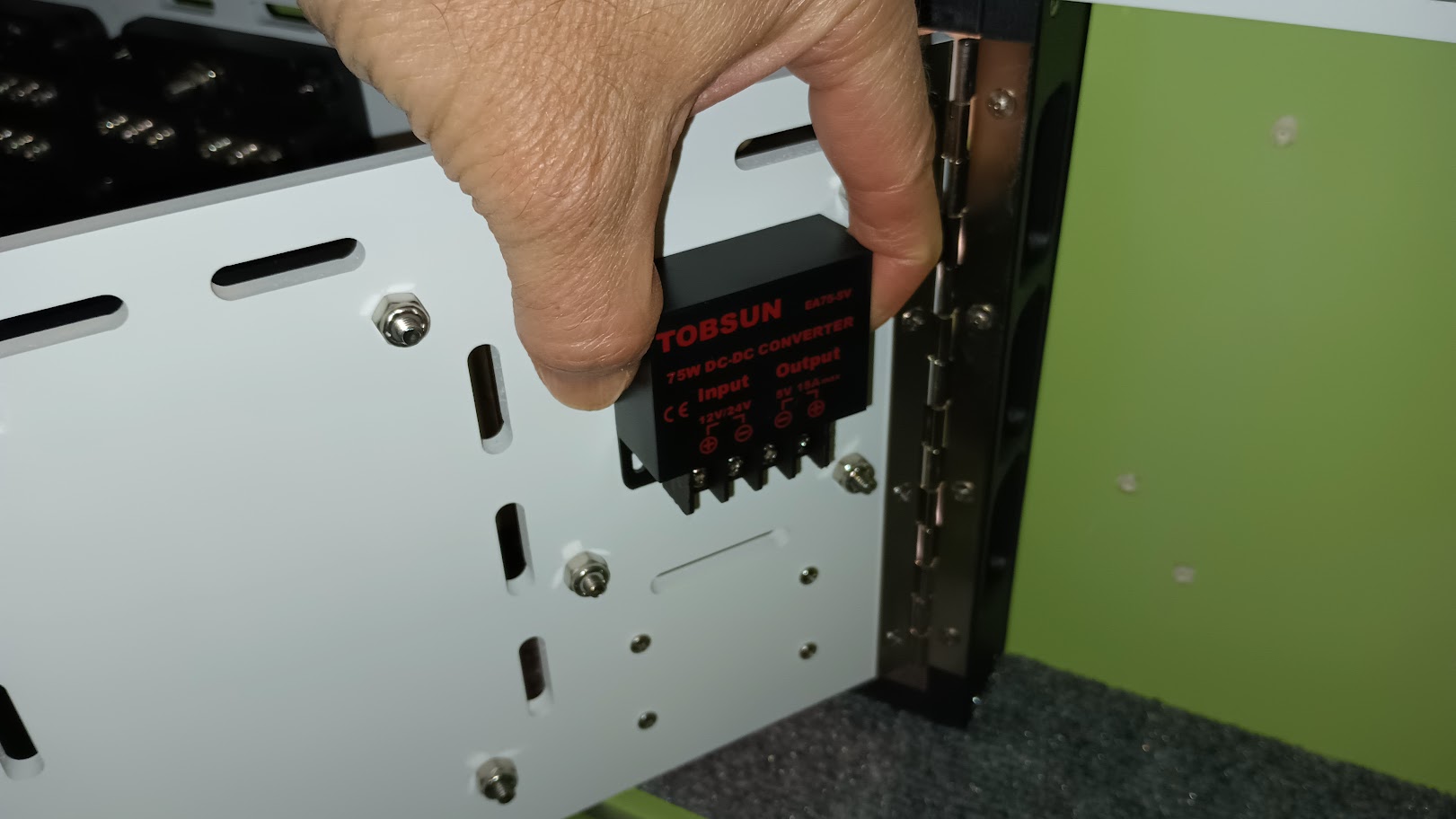
Hey guys, I wanted to start with a fresh Avionics Bay and Components tutorial thread because the path forward with our new v2.0 is so much different than our previous path(s). I say path(s) because to date, no two Lear45 sims have been built identically. Some close but no clones. Take a look at the old v1.0 Avionics Bay HERE As of this date I have stripped nearly everything out of my sim to make room for all the new v2.0 components and hardware. This is a photo of my new starting point! The path forward is to use 100% Arduino interface modules to run the Jet45 software that Jason is developing. Without going into too much detail, the idea is that all Lear45 sims in the future will use identical hardware and software making trouble shooting as easy as possible. Along with that, we wanted to develop a way to neatly mount all the modules, power supplies, wires and cables, again, an effort to reach some sort of uniformity among all the Lear45 simulators following this path. An idea that Shane and I came up with is to use swinging hinged panels that everything will be mounted to, including power supplies and electrical buses. This will keep everything neat and allow us to gain access to the the backside of the modules for easier wire routing. Here is a drawing of the initial idea that will probably change a little between now and the time it is "finished". Just in case you are seeing or hearing about this new v2.0 path forward for the first time, everything is designed to be hardwired to specific inputs and outputs, the same way a real aircraft would be designed and built. You can find the latest version of the Jet45-AAS-Systems-Modules Document HERE One quick point, the things you see in this thread are the best ideas we have at this moment. You can follow this tutorial exactly or pick and choose which ideas you like, or come up with your own. Nothing in this thread is mandatory if you want to move to the new v2.0 software, but you might find this thread will make things easier and in some cases enhance the simulation experience. Now that you are up to date with where we were and where we want to go, let's get this thread started! I wanted to start from the ground up so to speak and that being the Avionics Bay floor. "It's just a deck so how much can be done to update this area?" you might ask. Here is a photo of the old previous version. The only notable features to this previous version are that it is rectangular in shape and has access holes drilled along the back intended for cables and wires. This was a good idea back when the project first started but it turns out not many cables were actually routed through these holes. They were good for loosing screws though! Here is the new Avionics Bay floor! It is hard to detect but the shape is no longer rectangular. The left and right edges get wider the further back which follows the shape of the shell. The forward edge is the same as before, 34.75" but now the rear edge is set at 40". The next thing you notice is the access holes have been reduced to just two smaller holes in the center that will line up with the Cable Management Hub frame you will see later. Last but not least, is the deck hatch with finger latches. Maciej gets the credit for this idea! This access hatch will make it super easy to gain access under the Avionics Bay floor. As of this moment, I plan to mount the 5 volt power supply and blower motors under this deck. Other than that, you will find a surge protector and this is also where I will store extra cable lengths in an effort to keep things looks neat and tightly everywhere else. Here the hatch is removed. It took a minute to make this but it will be well worth the effort. I also made jigs of these pieces for future shell kits and paper plans. The underside of the Avionics Bay floor shows some aluminum framing that keeps the hatch from falling through the floor. I also added aluminum "L" angle to that back side of the hatch itself to make sure the wood never starts to bow. Here is the hatch sitting by itself. I used flush finger pull hardware to help remove the hatch. There are a million ways to do this, I wanted to try to keep it sleek and simple. If you have a cnc machine you can get fancy and let the cnc route out the pockets. This method keeps the back side of the hatch deck in tacked. This method is not necessary but if you have the tools you might as well use them. This results in a latch that is hidden from the underside. Otherwise, if you have to use a threw hole bit and jigsaw, the hardware would be visible. (Not the end of the world) Here is the new Avionics Bay floor installed in the shell! With the removable hatched installed! This is a close up photo of the new Cable Management Hub sitting on top of the new floor. Notice the cable access holes match up perfectly. One last photo of the edge attempting to show how the new floor follows the contour of the shell. Between getting rid of the six oversized cable access holes and the edges better following the contour of the shell, I have a lot less chance of dropping and loosing a screw under the floor. And if one does get away from me, I can now easily lift the hatch to find what it was I lost. I plan to keep pushing forward with the Avionics Bay until I get all of the structural items complete. I will let it be a surprise to you to see what's next! Any comments or questions just say or ask! Hey guys, I wanted to start with a fresh Avionics Bay and Components tutorial thread because the path forward with our new v2.0 is so much different than our previous path(s). I say path(s) because to date, no two Lear45 sims have been built identically. Some close but no clones. Take a look at the old v1.0 Avionics Bay HERE As of this date I have stripped nearly everything out of my sim to make room for all the new v2.0 components and hardware. This is a photo of my new starting point! The path forward is to use 100% Arduino interface modules to run the Jet45 software that Jason is developing. Without going into too much detail, the idea is that all Lear45 sims in the future will use identical hardware and software making trouble shooting as easy as possible. Along with that, we wanted to develop a way to neatly mount all the modules, power supplies, wires and cables, again, an effort to reach some sort of uniformity among all the Lear45 simulators following this path. An idea that Shane and I came up with is to use swinging hinged panels that everything will be mounted to, including power supplies and electrical buses. This will keep everything neat and allow us to gain access to the the backside of the modules for easier wire routing. Here is a drawing of the initial idea that will probably change a little between now and the time it is "finished". Just in case you are seeing or hearing about this new v2.0 path forward for the first time, everything is designed to be hardwired to specific inputs and outputs, the same way a real aircraft would be designed and built. You can find the latest version of the Jet45-AAS-Systems-Modules Document HERE One quick point, the things you see in this thread are the best ideas we have at this moment. You can follow this tutorial exactly or pick and choose which ideas you like, or come up with your own. Nothing in this thread is mandatory if you want to move to the new v2.0 software, but you might find this thread will make things easier and in some cases enhance the simulation experience. Now that you are up to date with where we were and where we want to go, let's get this thread started! I wanted to start from the ground up so to speak and that being the Avionics Bay floor. "It's just a deck so how much can be done to update this area?" you might ask. Here is a photo of the old previous version. The only notable features to this previous version are that it is rectangular in shape and has access holes drilled along the back intended for cables and wires. This was a good idea back when the project first started but it turns out not many cables were actually routed through these holes. They were good for loosing screws though! Here is the new Avionics Bay floor! It is hard to detect but the shape is no longer rectangular. The left and right edges get wider the further back which follows the shape of the shell. The forward edge is the same as before, 34.75" but now the rear edge is set at 40". The next thing you notice is the access holes have been reduced to just two smaller holes in the center that will line up with the Cable Management Hub frame you will see later. Last but not least, is the deck hatch with finger latches. Maciej gets the credit for this idea! This access hatch will make it super easy to gain access under the Avionics Bay floor. As of this moment, I plan to mount the 5 volt power supply and blower motors under this deck. Other than that, you will find a surge protector and this is also where I will store extra cable lengths in an effort to keep things looks neat and tightly everywhere else. Here the hatch is removed. It took a minute to make this but it will be well worth the effort. I also made jigs of these pieces for future shell kits and paper plans. The underside of the Avionics Bay floor shows some aluminum framing that keeps the hatch from falling through the floor. I also added aluminum "L" angle to that back side of the hatch itself to make sure the wood never starts to bow. Here is the hatch sitting by itself. I used flush finger pull hardware to help remove the hatch. There are a million ways to do this, I wanted to try to keep it sleek and simple. If you have a cnc machine you can get fancy and let the cnc route out the pockets. This method keeps the back side of the hatch deck in tacked. This method is not necessary but if you have the tools you might as well use them. This results in a latch that is hidden from the underside. Otherwise, if you have to use a threw hole bit and jigsaw, the hardware would be visible. (Not the end of the world) Here is the new Avionics Bay floor installed in the shell! With the removable hatched installed! This is a close up photo of the new Cable Management Hub sitting on top of the new floor. Notice the cable access holes match up perfectly. One last photo of the edge attempting to show how the new floor follows the contour of the shell. Between getting rid of the six oversized cable access holes and the edges better following the contour of the shell, I have a lot less chance of dropping and loosing a screw under the floor. And if one does get away from me, I can now easily lift the hatch to find what it was I lost. I plan to keep pushing forward with the Avionics Bay until I get all of the structural items complete. I will let it be a surprise to you to see what's next! Any comments or questions just say or ask! Nice updates. I will be updating my bay with the new floor and following to see what is next. Nice updates. I will be updating my bay with the new floor and following to see what is next. Hey guys, I just completed another step of the new and improved Avionics Bay! This update includes the Cable Management Hub, the hinged module panels and the installation of what I call the finger locks. First, you have make a Cable Management Hub and hinged module panels based on my dxf drawing or get the kit from me. Once everything is complete and we have worked out any issues in the Avionics Bay, I will be posting up the dxf drawing if you want to make any of these parts yourself. This kit includes the four main module panels, the Cable Management Hub frame with hinges and the finger locks. I will have this listed in the HANGAR PRODUCTS page soon. If you have the Project45 shell, installation of the kit is fairly straight forward. However, you might have to do a little trimming of the "tunnel" opening in F3 to get the Cable Management Hub to fit perfectly. In my case, I just used a scrap piece of wood to act as a router jig. The scrap wood is temporary screwed to the firewall in the Avionics Bay. The routing takes place from the cockpit side. Because the router bit is round and the corners of the Cable Management Hub are sharp, you will have to hand file the top inside corners of the new cut. And that's pretty much the only modification needed to install the Cable Management Hub. This is a view of the CMH in place from the cockpit side. Try to imagine hundreds of cables and wires running to and through this thing! Attachment holes are pre drilled. Don't tighten them down too hard because you will be needing that little bit of wiggle room during the installation of the finger locks. By the way, you might want to keep the protective paper on the panels until everything is installed. Truth be told I had to go back to the drawing board and make a couple minor adjustments to the finger locks. The first design might have been okay but to remove any possibility of them failing, I beefed them up. And......there is a process to finding the perfect place to mount them. If the locks are too tight, you will break them like the one to the left in the photo below. Too loose and the panels will not catch the lock slot and swing freely. First check to see how level your panels are. Keep in mind that your sim platform has to be level. Hold the finger locks in place while putting a little downward pressure on the panel to give it a load, simulating the weight of everything that will be attached to it. I only have two hands so there is no way to take the photo so you will have to use your imagination! Using a sharp tool, mark the exact hole point to be drilled. With all four panels, only worry about marking the lower hole. Trying to initially mark both is impossible. Once the lower hole is marked, drill a pilot hole and be careful not to bust through the other side. The MDF is .75" thick. Screw the finger lock in place. Now you can check to see if you "nailed it" or not. If not, this is where adjusting the screws holding the panel to the hing comes into play. You will find there is just enough play in the hinge holes to make the minor adjustments you need. When everything is tight, you will find that there is still some play in the panels, but this play is actually in the hinges! In this case, it is good because that little bit of play will allow you to lift the panel out of the finger lock slot. What I have found is that the Cable Management Hub is so strong and rigged that very little lift support is needed out on the ends. The finger locks main objective is to keep the panels secure and in place. They also give some support to the panels which is good because they will help take some of the stress off of the hinges. One last point about the finger locks, they are made of a softer Polly material compared to the Cast plastic that the panels are made of. We will want to lift the panels out of the finger lock slots in order to keep them from wearing down prematurely. In the future I might develop a metal slide guard. So once happy with the placement of the finger lock, check to make sure it is set to a 45 degree angle. This little level is great for this task. What I found here is that I would set the piece level, test the fit and find that the part has shifted to a position it liked better. After several set it and test it drills, I decided to go with what the panel and the finger lock agreed on which was slightly out of 45 degrees. Mark the dill point with the sharp tool. Drill the hole, screw that part to the bulkhead and if all went well, the panel will rest comfortably in the finger lock slot. When you want to gain access to the rear side of the panel, simply lift slightly with your fingers while your thumb rest on the finger lock. ( I was a hand model back in the late 80s) LOL This is one of those things that seems super simple and should only take an hour, but if you are not taking your time, paying attention, checking and double checking, you WILL screw up the placement of the finger locks. So don't start this task until you have a couple of uninterrupted hours to work within. Again, truth be told I screwed up and had to do this installation twice. But the good news is you guys will learn from my mistakes and hopefully yours will be a "one and done" installation. I have been meaning to share this photo with everyone for a while. It helps illustrate why I have such a hard time getting a good shot of the overall Avionics Bay. I could move the shell away from the screen but it is on stands and would be another big job in itself. The photo makes it look tighter than it is but I actually have plenty of room to work, just not enough room to take the best photos. And this is the best overall photo I can take considering the space restraints. So to date, I have an updated Avionics Bay floor, the Cable Management Hub and now the Module Panels with finger locks installed. This type of stuff is what I call foundation work. It is really starting to come along and I can't wait to start populating these panels with the Jet45 Modules! But before I can do that, I have a couple more Avionics Bay projects to square away. Keep an eye out for the updates! Hey guys, I just completed another step of the new and improved Avionics Bay! This update includes the Cable Management Hub, the hinged module panels and the installation of what I call the finger locks. First, you have make a Cable Management Hub and hinged module panels based on my dxf drawing or get the kit from me. Once everything is complete and we have worked out any issues in the Avionics Bay, I will be posting up the dxf drawing if you want to make any of these parts yourself. This kit includes the four main module panels, the Cable Management Hub frame with hinges and the finger locks. I will have this listed in the HANGAR PRODUCTS page soon. If you have the Project45 shell, installation of the kit is fairly straight forward. However, you might have to do a little trimming of the "tunnel" opening in F3 to get the Cable Management Hub to fit perfectly. In my case, I just used a scrap piece of wood to act as a router jig. The scrap wood is temporary screwed to the firewall in the Avionics Bay. The routing takes place from the cockpit side. Because the router bit is round and the corners of the Cable Management Hub are sharp, you will have to hand file the top inside corners of the new cut. And that's pretty much the only modification needed to install the Cable Management Hub. This is a view of the CMH in place from the cockpit side. Try to imagine hundreds of cables and wires running to and through this thing! Attachment holes are pre drilled. Don't tighten them down too hard because you will be needing that little bit of wiggle room during the installation of the finger locks. By the way, you might want to keep the protective paper on the panels until everything is installed. Truth be told I had to go back to the drawing board and make a couple minor adjustments to the finger locks. The first design might have been okay but to remove any possibility of them failing, I beefed them up. And......there is a process to finding the perfect place to mount them. If the locks are too tight, you will break them like the one to the left in the photo below. Too loose and the panels will not catch the lock slot and swing freely. First check to see how level your panels are. Keep in mind that your sim platform has to be level. Hold the finger locks in place while putting a little downward pressure on the panel to give it a load, simulating the weight of everything that will be attached to it. I only have two hands so there is no way to take the photo so you will have to use your imagination! Using a sharp tool, mark the exact hole point to be drilled. With all four panels, only worry about marking the lower hole. Trying to initially mark both is impossible. Once the lower hole is marked, drill a pilot hole and be careful not to bust through the other side. The MDF is .75" thick. Screw the finger lock in place. Now you can check to see if you "nailed it" or not. If not, this is where adjusting the screws holding the panel to the hing comes into play. You will find there is just enough play in the hinge holes to make the minor adjustments you need. When everything is tight, you will find that there is still some play in the panels, but this play is actually in the hinges! In this case, it is good because that little bit of play will allow you to lift the panel out of the finger lock slot. What I have found is that the Cable Management Hub is so strong and rigged that very little lift support is needed out on the ends. The finger locks main objective is to keep the panels secure and in place. They also give some support to the panels which is good because they will help take some of the stress off of the hinges. One last point about the finger locks, they are made of a softer Polly material compared to the Cast plastic that the panels are made of. We will want to lift the panels out of the finger lock slots in order to keep them from wearing down prematurely. In the future I might develop a metal slide guard. So once happy with the placement of the finger lock, check to make sure it is set to a 45 degree angle. This little level is great for this task. What I found here is that I would set the piece level, test the fit and find that the part has shifted to a position it liked better. After several set it and test it drills, I decided to go with what the panel and the finger lock agreed on which was slightly out of 45 degrees. Mark the dill point with the sharp tool. Drill the hole, screw that part to the bulkhead and if all went well, the panel will rest comfortably in the finger lock slot. When you want to gain access to the rear side of the panel, simply lift slightly with your fingers while your thumb rest on the finger lock. ( I was a hand model back in the late 80s) LOL This is one of those things that seems super simple and should only take an hour, but if you are not taking your time, paying attention, checking and double checking, you WILL screw up the placement of the finger locks. So don't start this task until you have a couple of uninterrupted hours to work within. Again, truth be told I screwed up and had to do this installation twice. But the good news is you guys will learn from my mistakes and hopefully yours will be a "one and done" installation. I have been meaning to share this photo with everyone for a while. It helps illustrate why I have such a hard time getting a good shot of the overall Avionics Bay. I could move the shell away from the screen but it is on stands and would be another big job in itself. The photo makes it look tighter than it is but I actually have plenty of room to work, just not enough room to take the best photos. And this is the best overall photo I can take considering the space restraints. So to date, I have an updated Avionics Bay floor, the Cable Management Hub and now the Module Panels with finger locks installed. This type of stuff is what I call foundation work. It is really starting to come along and I can't wait to start populating these panels with the Jet45 Modules! But before I can do that, I have a couple more Avionics Bay projects to square away. Keep an eye out for the updates! It's been a minute since I have been able to update this thread but don't think for a second that I haven't been hard at work. There are thousands of little things to think about when planning a build like this and the goal is to reduce the amount of times needed to cut something because of an oversight or two or three. I think I had to cut these large Avionics panels twice. As of right now, there are no changes needed, but that could change when I start running wiring harnesses to and through these panels. Here are several photos of each panel and the components attached to them. Left Power Panel: Right Power Panel: Left Avionics Panel: Right Avionics Panel: I ended up using aluminum standoffs because the Nylon standoffs were 5X more expensive. The aluminum standoffs were .29 cents compared to $1.50 for the Nylon standoffs. All the pcb is designed with "keep out" rings around the screw holes so there is no danger of damaging trace lines within the modules. Another thing I took a minute to do is make labels that go under the modules. This way if more than one module is removed, it will be easy to figure out where they go. I have learned that stuff like this might be fresh in my mind today, but several months or years later, not so much. If you recall, one of the really cool features to this design is that the Avionics Bay panels swing out to gain access to the back sides of them where the wiring harnesses will run. And of course they latch securely in place to the bulkhead. Progress! I have to say it is not necessary for builders to go this route although a few of us are. I chose to do this in an effort to showcase all the interface modules. In most flight sim builds, it is a mystery as to what it takes to interface a cockpit completely! No mystery here. With the exception of a few items like the CDU modules and the 5volt power supply for the back lighting, everything is mounted right here in plain sight. More updates soon! It's been a minute since I have been able to update this thread but don't think for a second that I haven't been hard at work. There are thousands of little things to think about when planning a build like this and the goal is to reduce the amount of times needed to cut something because of an oversight or two or three. I think I had to cut these large Avionics panels twice. As of right now, there are no changes needed, but that could change when I start running wiring harnesses to and through these panels. Here are several photos of each panel and the components attached to them. Left Power Panel: Right Power Panel: Left Avionics Panel: Right Avionics Panel: I ended up using aluminum standoffs because the Nylon standoffs were 5X more expensive. The aluminum standoffs were .29 cents compared to $1.50 for the Nylon standoffs. All the pcb is designed with "keep out" rings around the screw holes so there is no danger of damaging trace lines within the modules. Another thing I took a minute to do is make labels that go under the modules. This way if more than one module is removed, it will be easy to figure out where they go. I have learned that stuff like this might be fresh in my mind today, but several months or years later, not so much. If you recall, one of the really cool features to this design is that the Avionics Bay panels swing out to gain access to the back sides of them where the wiring harnesses will run. And of course they latch securely in place to the bulkhead. Progress! I have to say it is not necessary for builders to go this route although a few of us are. I chose to do this in an effort to showcase all the interface modules. In most flight sim builds, it is a mystery as to what it takes to interface a cockpit completely! No mystery here. With the exception of a few items like the CDU modules and the 5volt power supply for the back lighting, everything is mounted right here in plain sight. More updates soon! Ron, I've got to say that this aspect of the build is almost the most important. As one of the very few functioning sims around, without a shadow of doubt our nose wiring is a total spaghetti bolognaise. We even have wires and power packs spilling out onto the floor in order to make it functional. There may be other modules that one hasn't considered yet, which will depend on just how much you want to 'add' to your sim such as usb sound cards, more usb hubs, even an amplifier. But you have covered the basics fantastically and even more importantly allowed the horizontal deck to be free of clutter for any added shrapnel you might want to add down the track. As you can imagine, with our spaghetti tree, fault finding is a nightmare. I implore anyone to follow Rons example to make your life easier. Mark S and Mark C Ron, I've got to say that this aspect of the build is almost the most important. As one of the very few functioning sims around, without a shadow of doubt our nose wiring is a total spaghetti bolognaise. We even have wires and power packs spilling out onto the floor in order to make it functional. There may be other modules that one hasn't considered yet, which will depend on just how much you want to 'add' to your sim such as usb sound cards, more usb hubs, even an amplifier. But you have covered the basics fantastically and even more importantly allowed the horizontal deck to be free of clutter for any added shrapnel you might want to add down the track. As you can imagine, with our spaghetti tree, fault finding is a nightmare. I implore anyone to follow Rons example to make your life easier. Mark S and Mark C Looking very good indeed Ron. IMHO, this is the way to go, and it's perfect timing for my sim ! So it's onwards and upwards ! Looking very good indeed Ron. IMHO, this is the way to go, and it's perfect timing for my sim ! So it's onwards and upwards ! Exemplary work as always Ron. I presume these are hinged off F3, do you use offset hinges to leave a bit of room behind them? Exemplary work as always Ron. I presume these are hinged off F3, do you use offset hinges to leave a bit of room behind them? Thanks guys. Someone said way back that they thought I had some of the neatest wiring. Figured I had to live up to that. LOL One of the biggest check marks we are trying to hit is uniformity and the ability to help one another during trouble shooting efforts. Myself, Shane and Maciej are working towards leading the way with this Avionics layout plan. (Maciej recently moved to St. Pete Florida and will be OOC for a few months) If you can imagine, if one of us is having an issue and the rest of us are not, we can easily help trouble shoot the problem if it is hardware related. If it is software related, we should all be seeing the same problem. Speaking of trouble shooting, by now you are all aware of the way Jason is developing the new v2.0 software. It is actually a genius idea if you think about it. Think of the new V2 Lear45 build as a real aircraft or a vehicle coming off the assembly line. They are all programmed and wired exactly the same making it easy to trouble shoot issues. We will all have exactly the same version of the Lear45 that Jason has coded along with the interface modules. Will, if you scroll up to post #3 you will see that I designed a frame that stands out from the bulkhead about 1.25" giving enough room for the wiring harnesses to run behind. Once we have a couple sims wired up and proven, I will make sure everyone has access to all the dxf and G-Code files necessary to go this route, especially if you have a shell. You will need a cnc that is capable of cutting panels 12" X 24". If not, I can cut them for you once I am sure no changes are needed. Thanks guys. Someone said way back that they thought I had some of the neatest wiring. Figured I had to live up to that. LOL One of the biggest check marks we are trying to hit is uniformity and the ability to help one another during trouble shooting efforts. Myself, Shane and Maciej are working towards leading the way with this Avionics layout plan. (Maciej recently moved to St. Pete Florida and will be OOC for a few months) If you can imagine, if one of us is having an issue and the rest of us are not, we can easily help trouble shoot the problem if it is hardware related. If it is software related, we should all be seeing the same problem. Speaking of trouble shooting, by now you are all aware of the way Jason is developing the new v2.0 software. It is actually a genius idea if you think about it. Think of the new V2 Lear45 build as a real aircraft or a vehicle coming off the assembly line. They are all programmed and wired exactly the same making it easy to trouble shoot issues. We will all have exactly the same version of the Lear45 that Jason has coded along with the interface modules. Will, if you scroll up to post #3 you will see that I designed a frame that stands out from the bulkhead about 1.25" giving enough room for the wiring harnesses to run behind. Once we have a couple sims wired up and proven, I will make sure everyone has access to all the dxf and G-Code files necessary to go this route, especially if you have a shell. You will need a cnc that is capable of cutting panels 12" X 24". If not, I can cut them for you once I am sure no changes are needed. Hey guys, Shane and I have been pushing hard on the Avionics Bay and components. Before we can start running tons of cables and wires, we need to do all the "dirty work", cutting MDF and modifying the bulkhead and Avionics Bay deck. While working in the Bay, I was looking for a place to mount the 5 volt power supply that is going to supply power to all the backlit panels and it suddenly dawned on me........this is a bad idea! Why the heck did not someone pipe up and say, "Hey Ron, you need to be using a DC to DC converter, 12v to 5v to power your backlit panels." Don't get me wrong, we are still lighting up our panels with 5v power but we are going to do it a little differently. If we had used the 5v power supply for the backlit panels, it would have created other issues, like needing relays to trigger the 5v power supply. Moving forward, we are not going to need a separate 5v power supply! The solution to supplying 5v power is a DC to DC power converter like this one: Basically it takes 12 to 24 volt DC power and converts it to 5v DC power. This one can handle up to 15 amps and only cost $10 free shipping. They have several variations so be careful ordering them, you would need two of them. Why two? Because the Left LCU and the Ped LCU is going to be receiving power from the Left 12v power supply, via the L NON ESS bus and this 12v to 5v converter. And on the other side, the Right LCU will be receiving power from the Right 12v power supply, via the R NON ESS bus and a second 12v to 5v converter. Besides removing the need for a separate 5v power supply, wiring up the LCUs via these converters keeps our sims as close to what you would find in the real Lear45 as possible without getting ridiculous. Just two separate power sources, no third wheel. Cold and dark and bringing the sim to life will be super easy and no additional software logic needed other than what we already have planned when it comes to the relays controlling the L & R ESS and L & R NON ESS buses. I have been burned on a few things in the past so I did some extensive testing on the addition of this converter into the mix. I wanted to make sure it was converting 12v down to 5v first of all. This photos shows I have 12.18v power coming into the converter. And this one shows I have 5.08V power leaving the converter. (I could adjust the voltage on the 12v power supply and dial in 12.0 but for now, we are good.) From the converter, the 5v power has to run through a PWM so that we can dim all the panels that are on that LCU channel. This next photo shows that I am not detecting an EMI at the converter or anywhere else in this test. I loaded up my test LCU with the largest panels with the most LEDs in them. This test represents more LEDs than would be found in any of the LCU channels. I have eight panels and even one of the Davtron clocks that uses incandescent 5v bulbs. Everything passed! I could dim up or down all the panels using the PWM with no issues. The converter never got warm, it stayed cool to the touch. https://youtu.be/yjxFfHK4x_E The only thing that I found was when I touched the DC converter with the EMI detector tool. At this point, the tool would detect a small EMI field, but this is to be expected. I did not detect any EMI anywhere else, even in the wires running to all the panels etc... So we are good to go! Next question is where to mount these things? First thought was to mount them behind the LCUs on the Module Panels. But after some thought, the best place to mount them is behind the NON ESS buses on the lower Power Panels, something like this. The first reason why this is a good location is that power to the LCUs come from the NON ESS buses requiring short wires from the NON ESS bus terminals on the front side to the 12v IN terminals on the converter. Then the 5v OUT has to run through the PWM which is mounted on either the Left Crew Panel or the Environmental Panel, depending on which one you are working with. And then the power lines run back to the LCUs. Last but not least, lines run from the LCU to all the panels on that receptive light channel! Whew... The second good reason to mount the converter behind the NON ESS bus is it does have the potential to emit EMI. The one I tested did not have any EMI and I would say it is 100% good to go. But you know electronics, you could get a bad one or with time, they can go bad but still work. Fans are a good example of something that could still work but turned itself into a EMI blow torch! This all goes along with the thinking that we want to keep power supplies, fans or anything that has the potential to emit EMI as far away from the interface modules as practical. I have found that in most cases, a good distance is just a matter of inches. More updates on the Avionics Bay progress soon! Hey guys, Shane and I have been pushing hard on the Avionics Bay and components. Before we can start running tons of cables and wires, we need to do all the "dirty work", cutting MDF and modifying the bulkhead and Avionics Bay deck. While working in the Bay, I was looking for a place to mount the 5 volt power supply that is going to supply power to all the backlit panels and it suddenly dawned on me........this is a bad idea! Why the heck did not someone pipe up and say, "Hey Ron, you need to be using a DC to DC converter, 12v to 5v to power your backlit panels." Don't get me wrong, we are still lighting up our panels with 5v power but we are going to do it a little differently. If we had used the 5v power supply for the backlit panels, it would have created other issues, like needing relays to trigger the 5v power supply. Moving forward, we are not going to need a separate 5v power supply! The solution to supplying 5v power is a DC to DC power converter like this one: Basically it takes 12 to 24 volt DC power and converts it to 5v DC power. This one can handle up to 15 amps and only cost $10 free shipping. They have several variations so be careful ordering them, you would need two of them. Why two? Because the Left LCU and the Ped LCU is going to be receiving power from the Left 12v power supply, via the L NON ESS bus and this 12v to 5v converter. And on the other side, the Right LCU will be receiving power from the Right 12v power supply, via the R NON ESS bus and a second 12v to 5v converter. Besides removing the need for a separate 5v power supply, wiring up the LCUs via these converters keeps our sims as close to what you would find in the real Lear45 as possible without getting ridiculous. Just two separate power sources, no third wheel. Cold and dark and bringing the sim to life will be super easy and no additional software logic needed other than what we already have planned when it comes to the relays controlling the L & R ESS and L & R NON ESS buses. I have been burned on a few things in the past so I did some extensive testing on the addition of this converter into the mix. I wanted to make sure it was converting 12v down to 5v first of all. This photos shows I have 12.18v power coming into the converter. And this one shows I have 5.08V power leaving the converter. (I could adjust the voltage on the 12v power supply and dial in 12.0 but for now, we are good.) From the converter, the 5v power has to run through a PWM so that we can dim all the panels that are on that LCU channel. This next photo shows that I am not detecting an EMI at the converter or anywhere else in this test. I loaded up my test LCU with the largest panels with the most LEDs in them. This test represents more LEDs than would be found in any of the LCU channels. I have eight panels and even one of the Davtron clocks that uses incandescent 5v bulbs. Everything passed! I could dim up or down all the panels using the PWM with no issues. The converter never got warm, it stayed cool to the touch. The only thing that I found was when I touched the DC converter with the EMI detector tool. At this point, the tool would detect a small EMI field, but this is to be expected. I did not detect any EMI anywhere else, even in the wires running to all the panels etc... So we are good to go! Next question is where to mount these things? First thought was to mount them behind the LCUs on the Module Panels. But after some thought, the best place to mount them is behind the NON ESS buses on the lower Power Panels, something like this. The first reason why this is a good location is that power to the LCUs come from the NON ESS buses requiring short wires from the NON ESS bus terminals on the front side to the 12v IN terminals on the converter. Then the 5v OUT has to run through the PWM which is mounted on either the Left Crew Panel or the Environmental Panel, depending on which one you are working with. And then the power lines run back to the LCUs. Last but not least, lines run from the LCU to all the panels on that receptive light channel! Whew... The second good reason to mount the converter behind the NON ESS bus is it does have the potential to emit EMI. The one I tested did not have any EMI and I would say it is 100% good to go. But you know electronics, you could get a bad one or with time, they can go bad but still work. Fans are a good example of something that could still work but turned itself into a EMI blow torch! This all goes along with the thinking that we want to keep power supplies, fans or anything that has the potential to emit EMI as far away from the interface modules as practical. I have found that in most cases, a good distance is just a matter of inches. More updates on the Avionics Bay progress soon! Glad that worked. This will make it much easier than dealing with extra 5v power supplies. Glad that worked. This will make it much easier than dealing with extra 5v power supplies.Avionics Bay and Components v2.0
![]()


![]()
![]()

![]()

![]()
![]()
![]()
![]()
![]()
![]()
Forum NavigationAvionics Bay and Components v2.0
![]() #1 · March 3, 2022, 10:12 am
#1 · March 3, 2022, 10:12 am![]() #2 · March 12, 2022, 9:58 am
#2 · March 12, 2022, 9:58 am![]() #3 · March 15, 2022, 2:31 pmTerryC has reacted to this post.TerryC
#3 · March 15, 2022, 2:31 pmTerryC has reacted to this post.TerryC![]() #4 · November 5, 2022, 9:56 pm
#4 · November 5, 2022, 9:56 pm![]() #5 · November 6, 2022, 1:49 am
#5 · November 6, 2022, 1:49 am![]() #6 · November 6, 2022, 6:16 am
#6 · November 6, 2022, 6:16 am![]() #7 · November 6, 2022, 7:22 am
#7 · November 6, 2022, 7:22 am![]() #8 · November 6, 2022, 11:10 am
#8 · November 6, 2022, 11:10 am![]() #9 · November 23, 2022, 12:45 pm
#9 · November 23, 2022, 12:45 pm![]() #10 · November 27, 2022, 3:37 pm
#10 · November 27, 2022, 3:37 pm
2017-10-10