


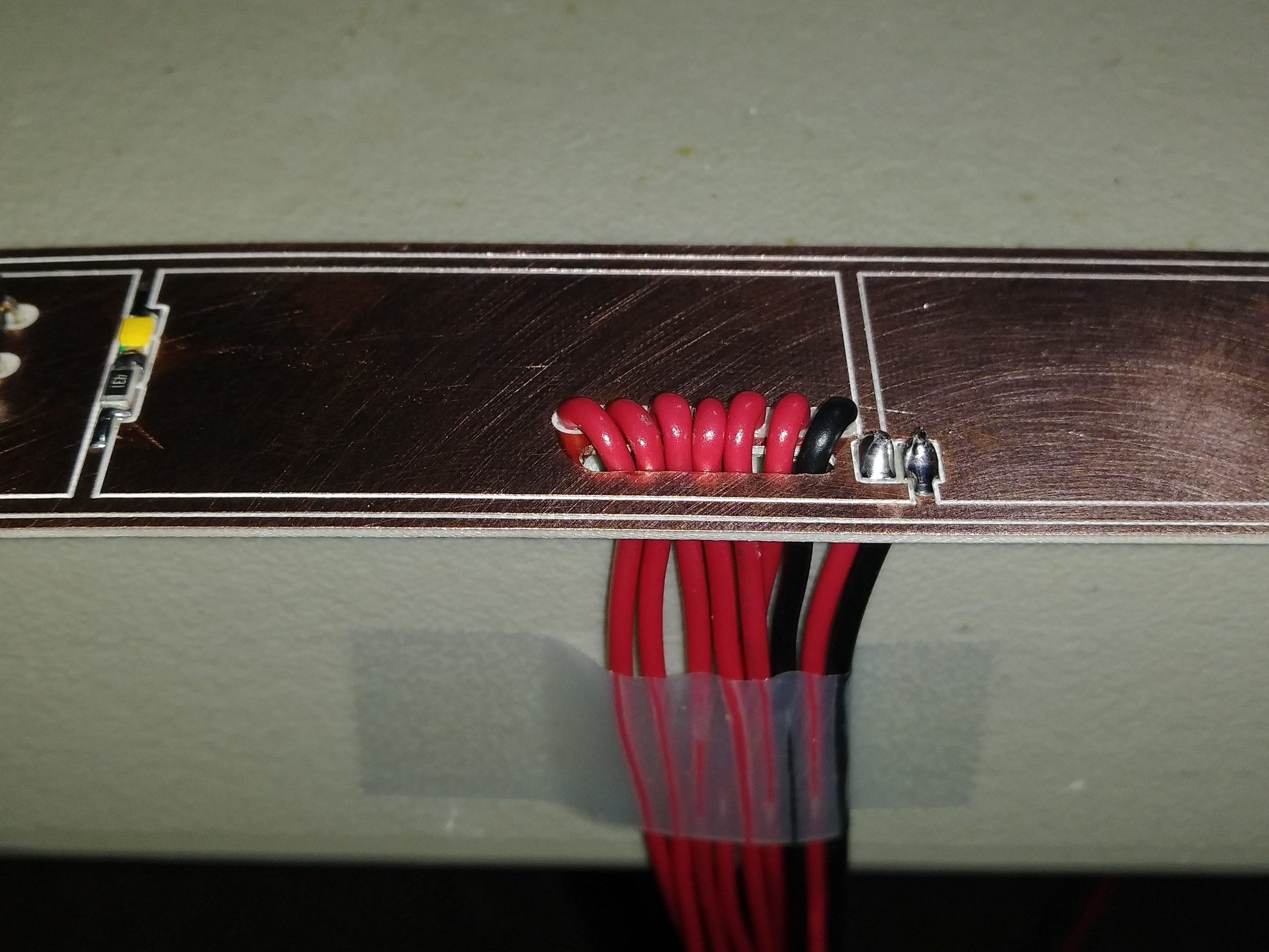
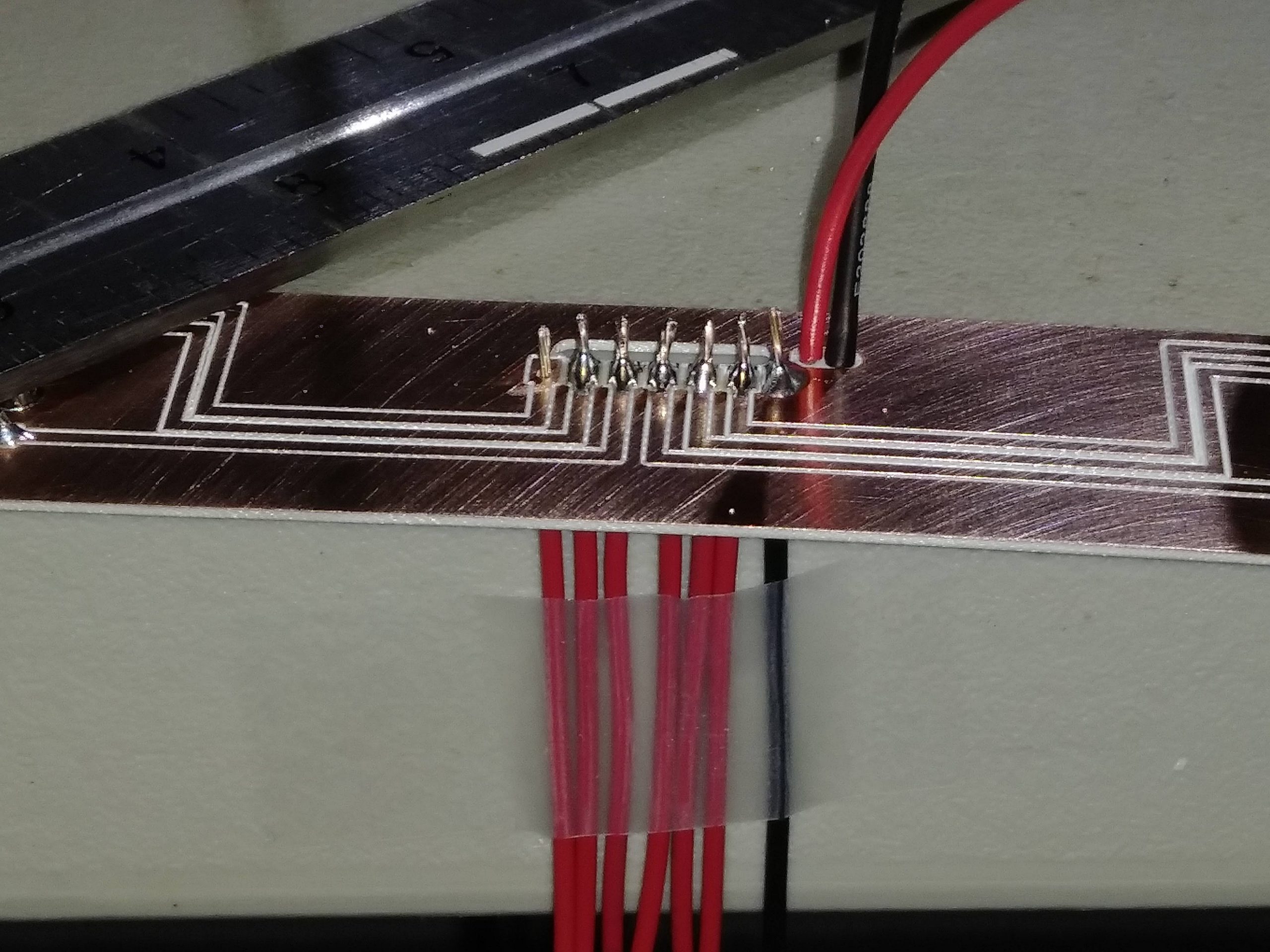
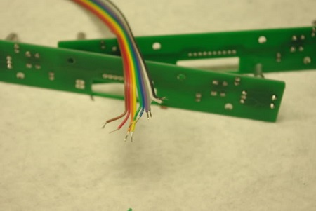
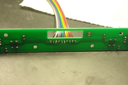
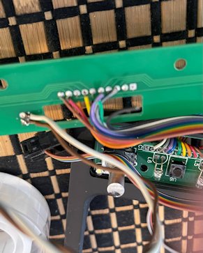
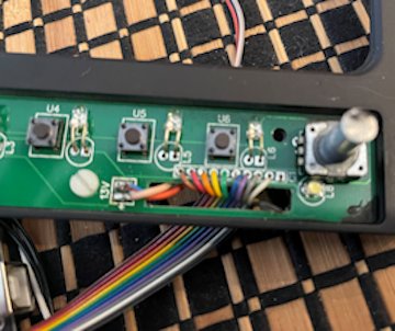
I'm trying to get these bezels to work with Pokeys or Arduino. I purchased these from Alan Norris. He no longer answers his email. I found a couple odd broken wires from each unit (PFD & MFD/EICAS). Any hints - techniques to reattach. Can barley see the ends of the wire (I'm getting Old)! Also, does anyone know which wires are to which functions? The patch cables (female to female) weren't included. Or at least provide techniques to trace wiring with a meter for the pots. I think I can handle the push buttons. I did figure out pin assignments. The issue is there are detached wires on each PCB. Vince did not use any glue to keep wires from detaching. Any hints or techniques to replace the wiring. Each solder terminal is about 3/64" with a 1/32" separation. Hi Ron, is your PCB terminals this small? Thanks for your continuing help. I'm trying to get these bezels to work with Pokeys or Arduino. I purchased these from Alan Norris. He no longer answers his email. I found a couple odd broken wires from each unit (PFD & MFD/EICAS). Any hints - techniques to reattach. Can barley see the ends of the wire (I'm getting Old)! Also, does anyone know which wires are to which functions? The patch cables (female to female) weren't included. Or at least provide techniques to trace wiring with a meter for the pots. I think I can handle the push buttons. I did figure out pin assignments. The issue is there are detached wires on each PCB. Vince did not use any glue to keep wires from detaching. Any hints or techniques to replace the wiring. Each solder terminal is about 3/64" with a 1/32" separation. Hi Ron, is your PCB terminals this small? Thanks for your continuing help. It’s going to be fairly precise operation to reattach these. Proper clean up and equipment is going to be critical. I would take it to any electronics repair shop and let them do it. Also, I sent you an email few days ago… It’s going to be fairly precise operation to reattach these. Proper clean up and equipment is going to be critical. I would take it to any electronics repair shop and let them do it. Also, I sent you an email few days ago… Hi Dave, I think we are all going blind, at least all of us over 45 years of age. I now typically use 1.5 readers for computer stuff like right now and if I am soldering small stuff I use 2.5 readers. And in rare occasions you will find me wearing both my 1.5s on top of my 2.5s to get in REALLY close. So unless your eyes are just done, you should be able to find a way to get in close enough to repair stuff like this. I had Vince's Display Units and his RMUs which were made in the same way with the ribbon cables. Not the best design but at the time very functional. The problem was and still is we have a LCD screen directly behind the DU and RMU bezels and the bezels have to be flat on the back. Only the wires can protrude from the rear and then they have to lay flat. The ribbon cable allows the wires to lay flat, however, they are prone to failing. I had one fail on one of the RMUs and had to do a little surgery to fix it. I had to add a jumper wire to bridge the connection. Same thing on one of his EFIS panels. To answer your question about my PCB terminal and how small they are, my design on the DUs use double sided clad. My wires thread through the clad, do a 180 degree turn and then solder to the clad. This way any stress is put on the wire with insulation, not the solder point. This second photo shows the wires prior to being threaded through the clad and the ends trimmed. This info does not help your issue at hand but does show my solution to preventing this problem from happening in the first place. I no longer have a set of Vince's DUs but have a couple photos of the pcb boards that he used. Your fix may require you to desolder all the wires from the ribbon cable and resoldering the ribbon cable. Or just adding a jumper wire from the broken connection to the solder point that the trace line leads to. If you are not comfortable with doing this fix on your own, as Maciej said, find an electronic repair shop. If you can find a TV repair shop that would be your best bet. They can fix stuff like this in their sleep. Last point, welcome to the club of trying to figure out what wire goes to what. Best way to go about this is with an ohm meter and document the results on paper. I wish I could give you a better answer but honestly, even my DU wires are not marked and require the same procedure to figure out what is what. I hope this info helps get you to where you need to be. Hi Dave, I think we are all going blind, at least all of us over 45 years of age. I now typically use 1.5 readers for computer stuff like right now and if I am soldering small stuff I use 2.5 readers. And in rare occasions you will find me wearing both my 1.5s on top of my 2.5s to get in REALLY close. So unless your eyes are just done, you should be able to find a way to get in close enough to repair stuff like this. I had Vince's Display Units and his RMUs which were made in the same way with the ribbon cables. Not the best design but at the time very functional. The problem was and still is we have a LCD screen directly behind the DU and RMU bezels and the bezels have to be flat on the back. Only the wires can protrude from the rear and then they have to lay flat. The ribbon cable allows the wires to lay flat, however, they are prone to failing. I had one fail on one of the RMUs and had to do a little surgery to fix it. I had to add a jumper wire to bridge the connection. Same thing on one of his EFIS panels. To answer your question about my PCB terminal and how small they are, my design on the DUs use double sided clad. My wires thread through the clad, do a 180 degree turn and then solder to the clad. This way any stress is put on the wire with insulation, not the solder point. This second photo shows the wires prior to being threaded through the clad and the ends trimmed. This info does not help your issue at hand but does show my solution to preventing this problem from happening in the first place. I no longer have a set of Vince's DUs but have a couple photos of the pcb boards that he used. Your fix may require you to desolder all the wires from the ribbon cable and resoldering the ribbon cable. Or just adding a jumper wire from the broken connection to the solder point that the trace line leads to. If you are not comfortable with doing this fix on your own, as Maciej said, find an electronic repair shop. If you can find a TV repair shop that would be your best bet. They can fix stuff like this in their sleep. Last point, welcome to the club of trying to figure out what wire goes to what. Best way to go about this is with an ohm meter and document the results on paper. I wish I could give you a better answer but honestly, even my DU wires are not marked and require the same procedure to figure out what is what. I hope this info helps get you to where you need to be. Hi Dave, I have and still use Vince’s DU’s & RMU’s. I did replace all cables due to broken or dry solder joints. I use rainbow ribbon cable on all my panels and so long as I ensure some form of strain relief (either hot-glueing wires to a fixture or heat shrinking connection) I have yet to have a problem. It is important to ensure your wire-stripping tool has a light touch as it is easy to strip both the sheathing and the wires. As Ron says, it’s good for the panels in front of the screens, especially the CWP - i have two 9” screens mounted directly to the back of the MIP on top of the ribbon cables from the CWP and RMU’s For identifying switch/wire combos, you could create a tool1 as per the V2.0 wiring loom test. The ‘pots’ are encoders, the tool also identifies the encoder wire pairs. If you’ve got bare wires at the end it makes it messy though. if you want to use a multi meter connect one end to the common wire for the panel (assuming that is connected to the encoder), then check each wire for continuity whilst turning the encoder. It should cycle in and out of continuity on each of the 2 signal wires. If you can identify the 3 wires coming from the encoders the middle one is the common and the outer 2 are the signal wires. It’s been a while since I looked at the DU wiring, but if you need I can check my wiring. Hi Dave, I have and still use Vince’s DU’s & RMU’s. I did replace all cables due to broken or dry solder joints. I use rainbow ribbon cable on all my panels and so long as I ensure some form of strain relief (either hot-glueing wires to a fixture or heat shrinking connection) I have yet to have a problem. It is important to ensure your wire-stripping tool has a light touch as it is easy to strip both the sheathing and the wires. As Ron says, it’s good for the panels in front of the screens, especially the CWP - i have two 9” screens mounted directly to the back of the MIP on top of the ribbon cables from the CWP and RMU’s For identifying switch/wire combos, you could create a tool1 as per the V2.0 wiring loom test. The ‘pots’ are encoders, the tool also identifies the encoder wire pairs. If you’ve got bare wires at the end it makes it messy though. if you want to use a multi meter connect one end to the common wire for the panel (assuming that is connected to the encoder), then check each wire for continuity whilst turning the encoder. It should cycle in and out of continuity on each of the 2 signal wires. If you can identify the 3 wires coming from the encoders the middle one is the common and the outer 2 are the signal wires. It’s been a while since I looked at the DU wiring, but if you need I can check my wiring. Good points Will. That last bit reminded me that we had Vince isolate the encoders from the other buttons. In other words, the encoders have their own dedicated ground so that they can be connected to a different type of interface board. Back when we first started, the FDS SYS boards that we were using did not and still do not support encoders. We had to use Pokeys as an example to support the encoders while all the buttons were handled by the SYS boards. So Dave, on each of the DUs, you will find at least two grounds, one for the buttons and one for the encoder. And for the DUs with two encoders, you might find that each encoder has it's own ground meaning you will find up to three grounds. And if you do not know this, it might explain why you are having a hard time identifying all the wires. Just to throw this in here, my new DUs are designed so that everything has a common ground thanks to Jason and the new way we are interfacing everything. It certainly helps simplify things. As an example, from a quick glance at the photo below, I can see that the six signal lines are the red wires to the left. Those six signal lines include the one encoder which has two signal lines. The other four red signal lines are for the four buttons on this DU. The black wire grouped with the six red wires is the common ground. The other two wires to the far right, red and black are for 5 volt backlighting. Knowing this is half the battle. Identifying what each of the signal lines is easy with a meter as Will pointed out. Again, this last bit of information may not help with your situation directly but the principle is the same. Will has some great points and I really like the idea of using hot glue to sure things up if needed and I will keep that as an option if I find a place that needs a little extra support. Good points Will. That last bit reminded me that we had Vince isolate the encoders from the other buttons. In other words, the encoders have their own dedicated ground so that they can be connected to a different type of interface board. Back when we first started, the FDS SYS boards that we were using did not and still do not support encoders. We had to use Pokeys as an example to support the encoders while all the buttons were handled by the SYS boards. So Dave, on each of the DUs, you will find at least two grounds, one for the buttons and one for the encoder. And for the DUs with two encoders, you might find that each encoder has it's own ground meaning you will find up to three grounds. And if you do not know this, it might explain why you are having a hard time identifying all the wires. Just to throw this in here, my new DUs are designed so that everything has a common ground thanks to Jason and the new way we are interfacing everything. It certainly helps simplify things. As an example, from a quick glance at the photo below, I can see that the six signal lines are the red wires to the left. Those six signal lines include the one encoder which has two signal lines. The other four red signal lines are for the four buttons on this DU. The black wire grouped with the six red wires is the common ground. The other two wires to the far right, red and black are for 5 volt backlighting. Knowing this is half the battle. Identifying what each of the signal lines is easy with a meter as Will pointed out. Again, this last bit of information may not help with your situation directly but the principle is the same. Will has some great points and I really like the idea of using hot glue to sure things up if needed and I will keep that as an option if I find a place that needs a little extra support. Thank you everyone for your input. I have an appointment at a computer repair to replace the wires. I use 10 wire and 20 wire ribbons with colors. Able to keep track of to and from pins. Only when the ribbon is all the same color is it an issue. I was able to trace the circuits on each PCB to the output pin. I also have been using a glue gun to deposit glue on the terminals. It holds the wire from bending and separating. If carefully placed, it is easy to remove. Even use that glue to hold the ribbon to the board where necessary. The photos show where the wires have come off the boards. This wiring will now feed and Arduino Mega with Mobiflight. Thank you everyone for your input. I have an appointment at a computer repair to replace the wires. I use 10 wire and 20 wire ribbons with colors. Able to keep track of to and from pins. Only when the ribbon is all the same color is it an issue. I was able to trace the circuits on each PCB to the output pin. I also have been using a glue gun to deposit glue on the terminals. It holds the wire from bending and separating. If carefully placed, it is easy to remove. Even use that glue to hold the ribbon to the board where necessary. The photos show where the wires have come off the boards. This wiring will now feed and Arduino Mega with Mobiflight. Dave. I sent you another email. Dave. I sent you another email.Vince Cimmino Bezels
![]()
![]()
![]()
![]()
![]()
![]()
![]()
![]()
2017-10-10