


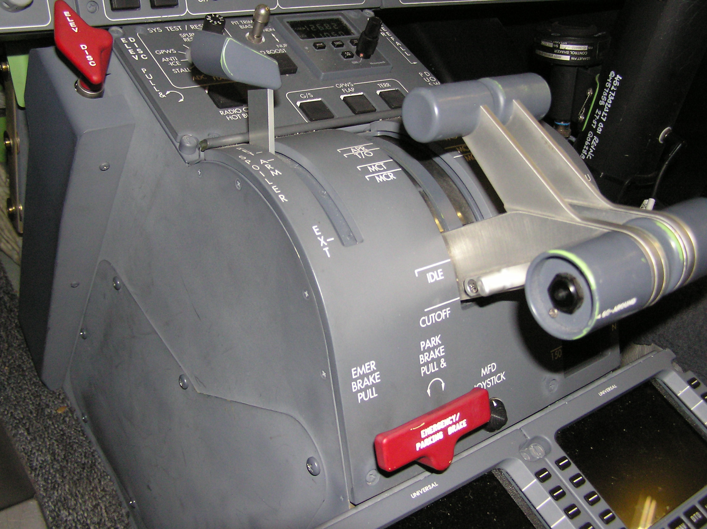
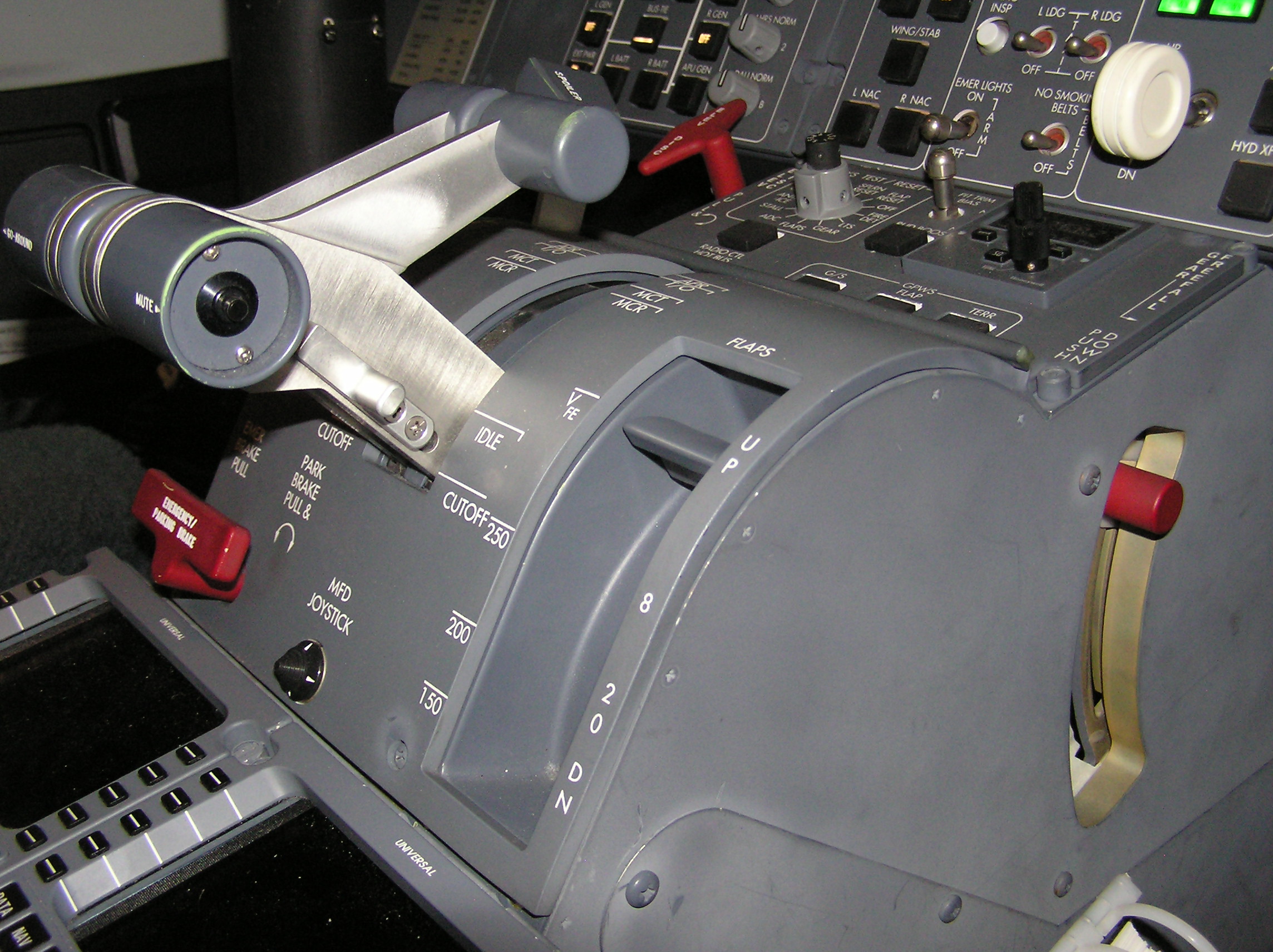
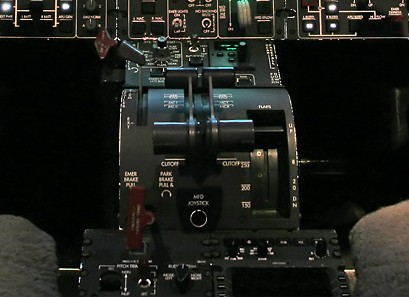
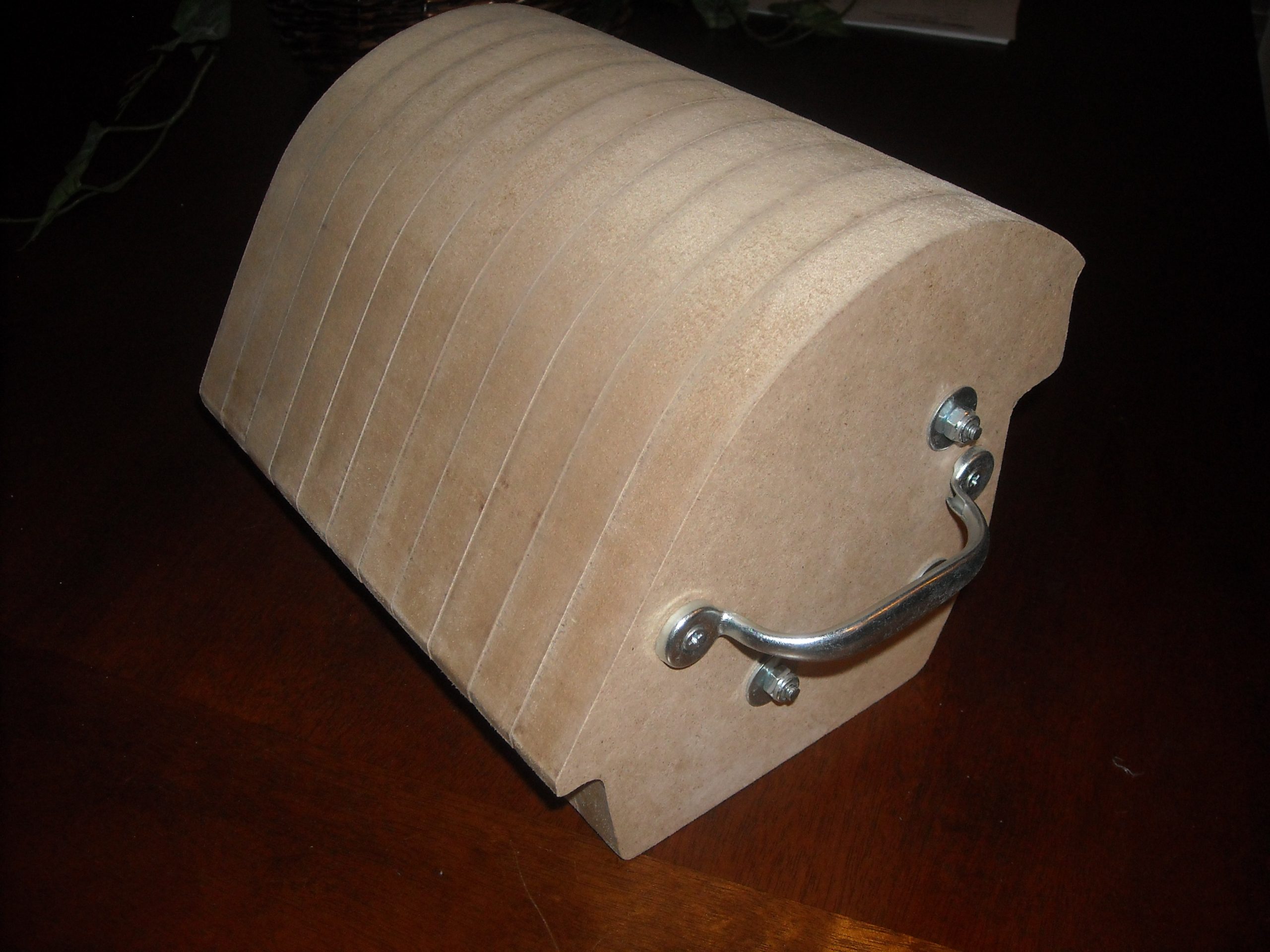
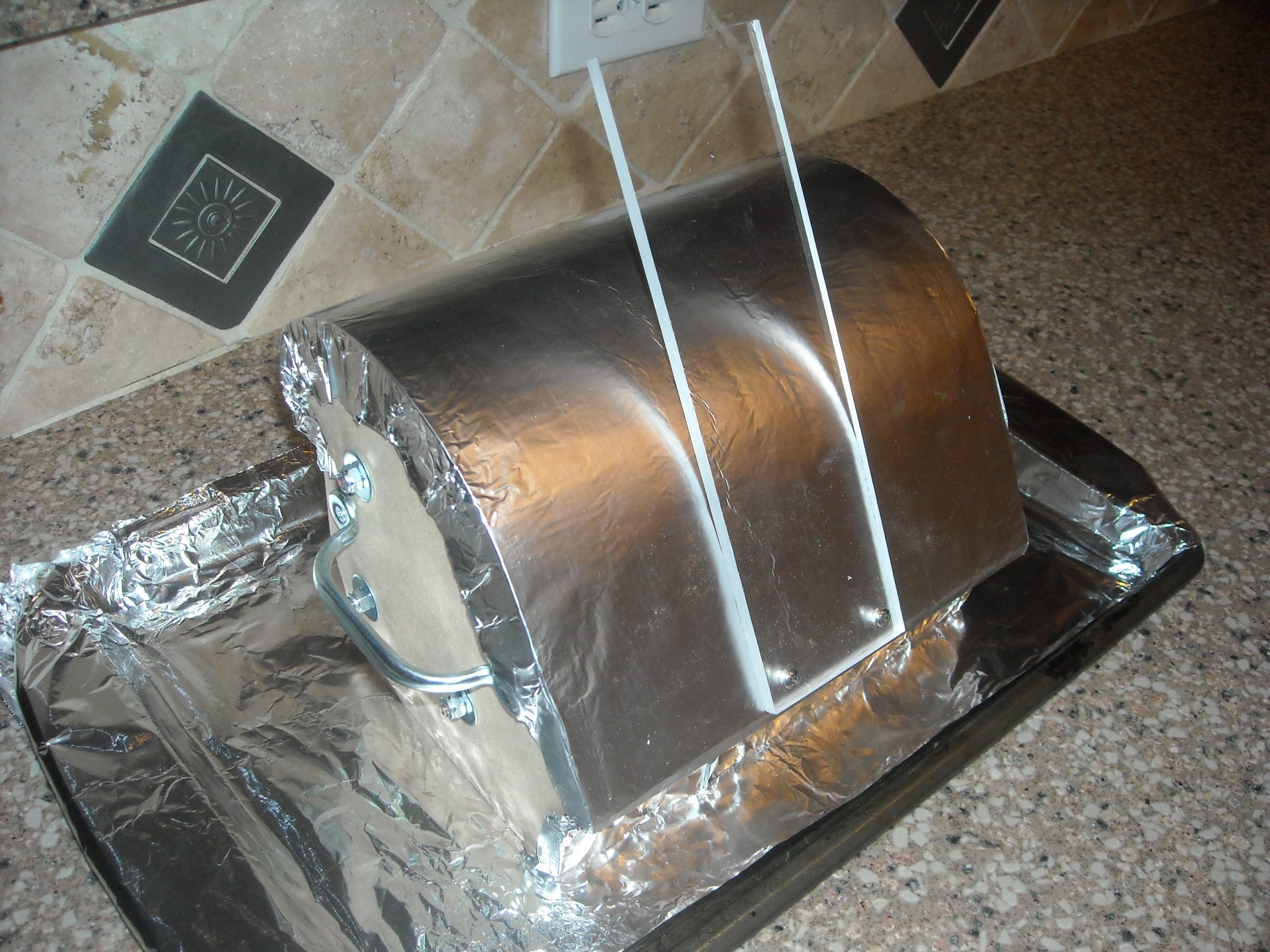
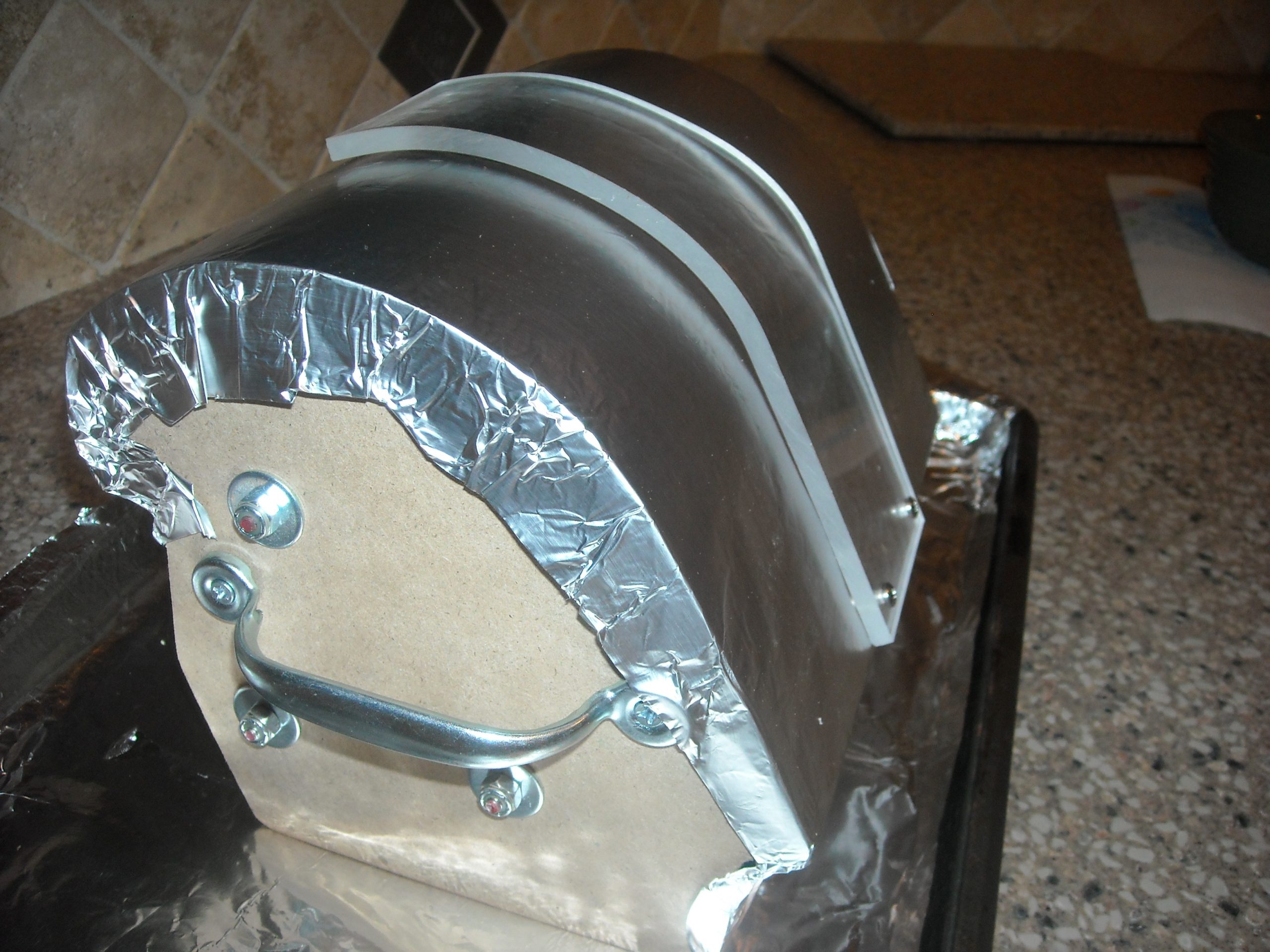
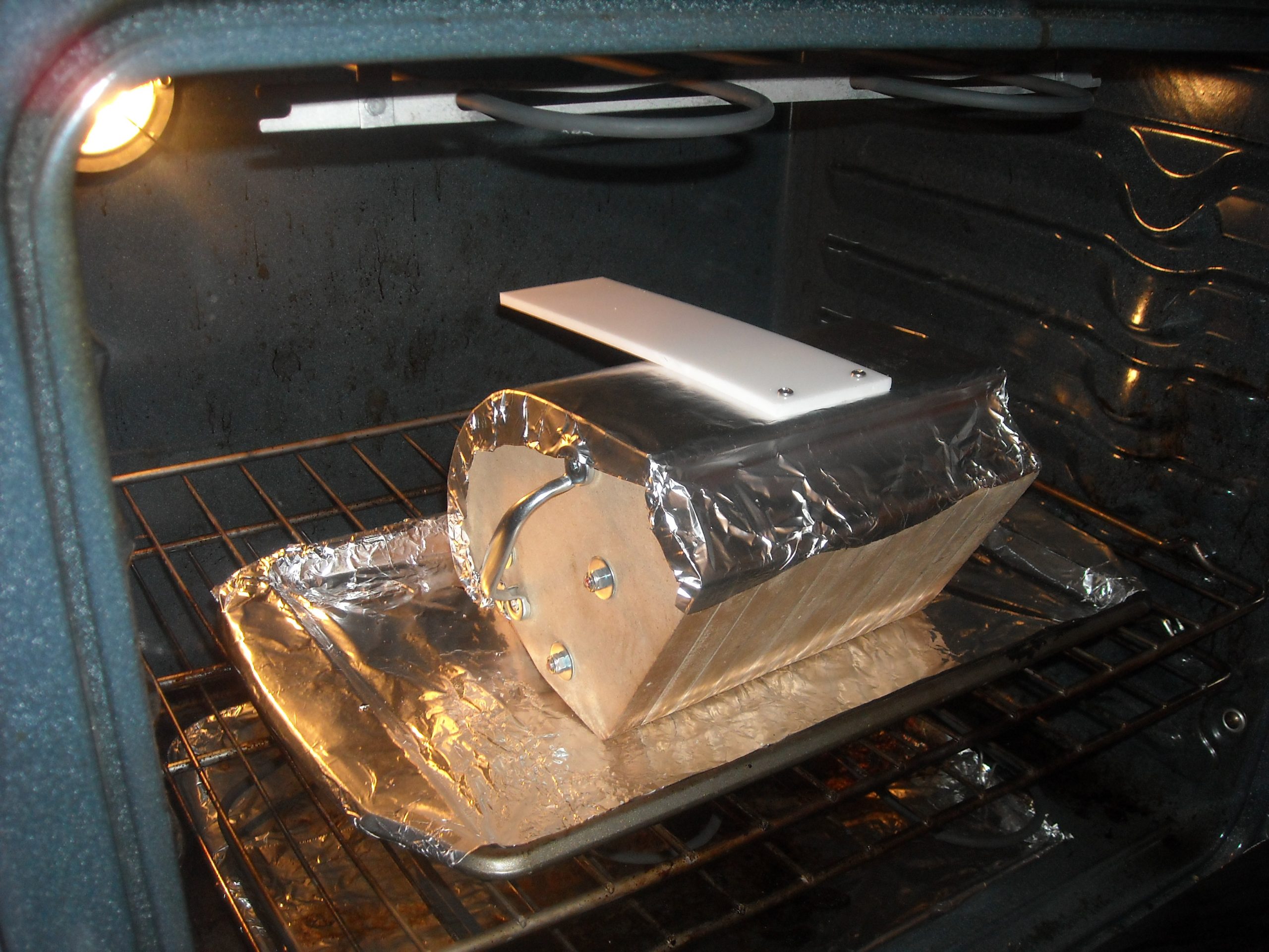
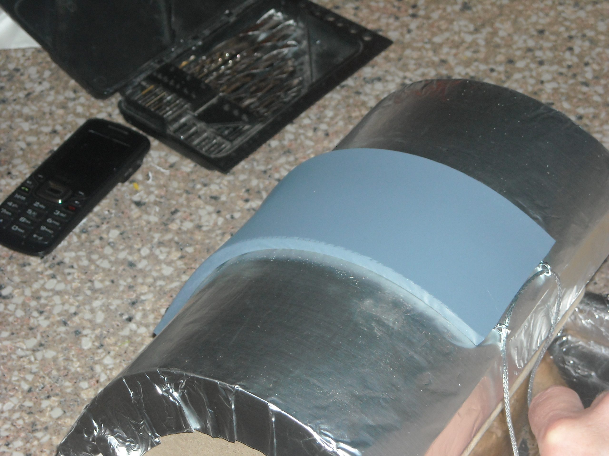
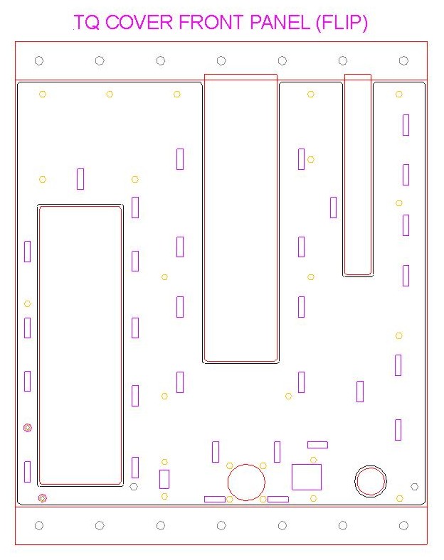
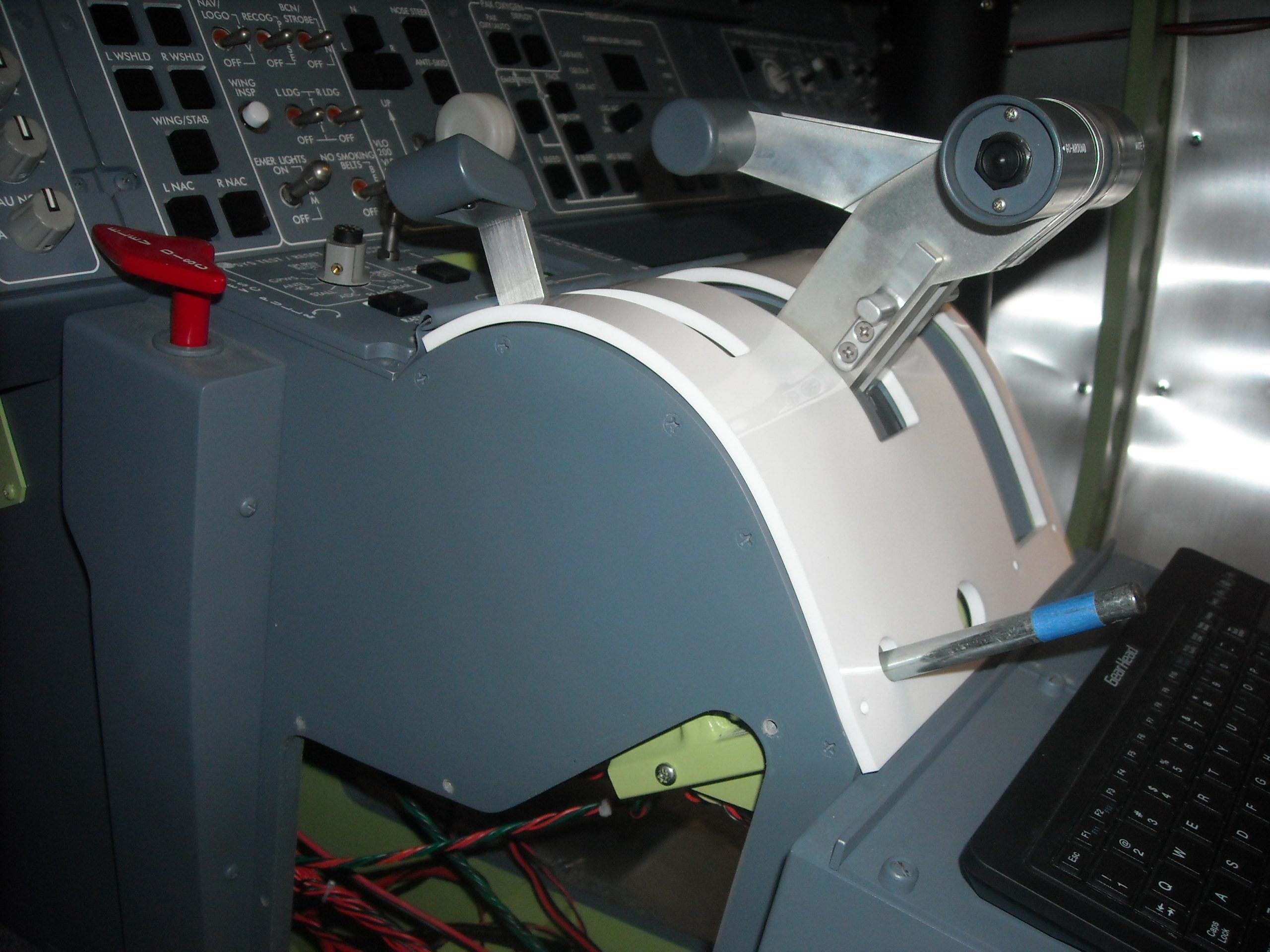
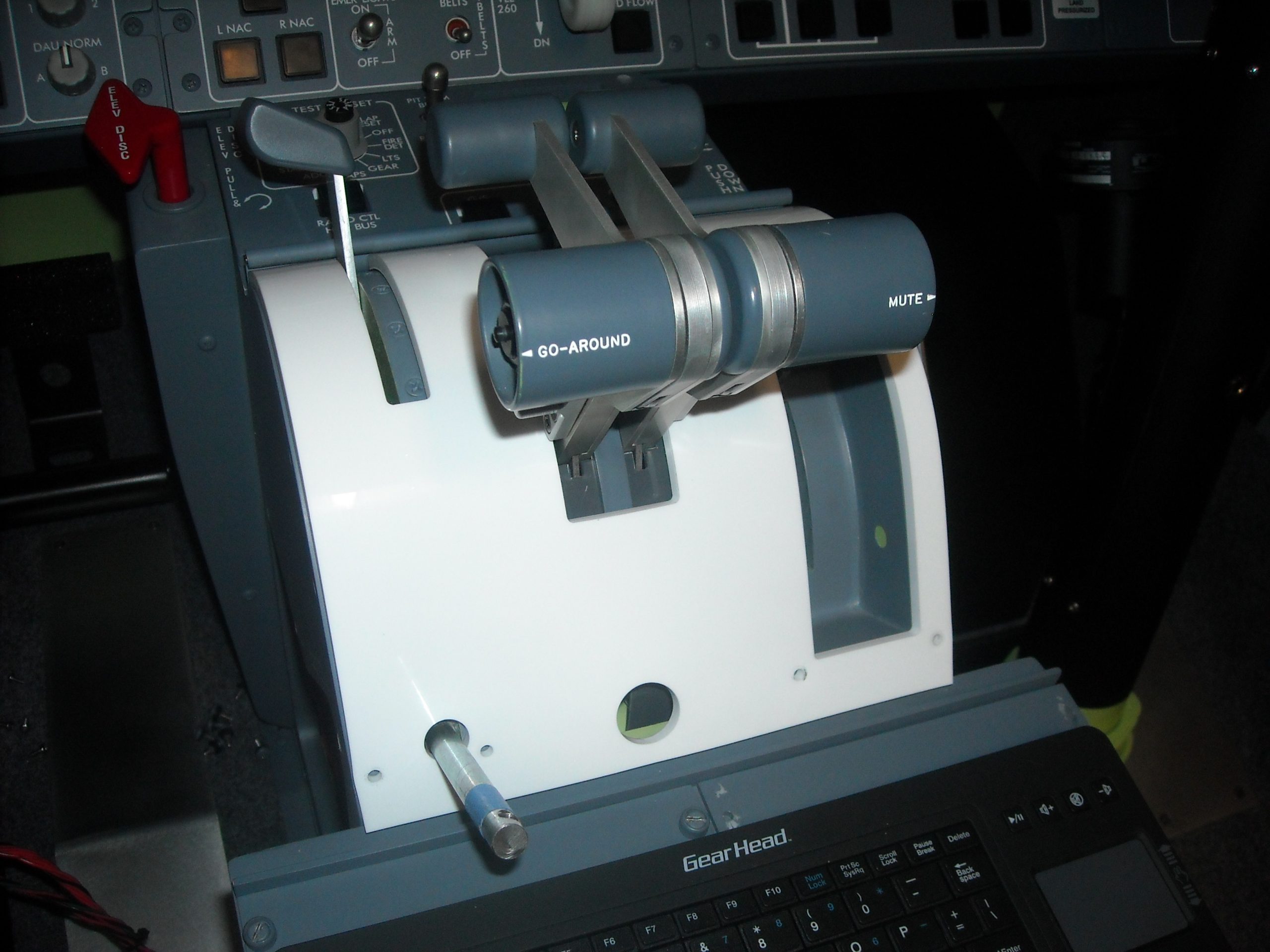
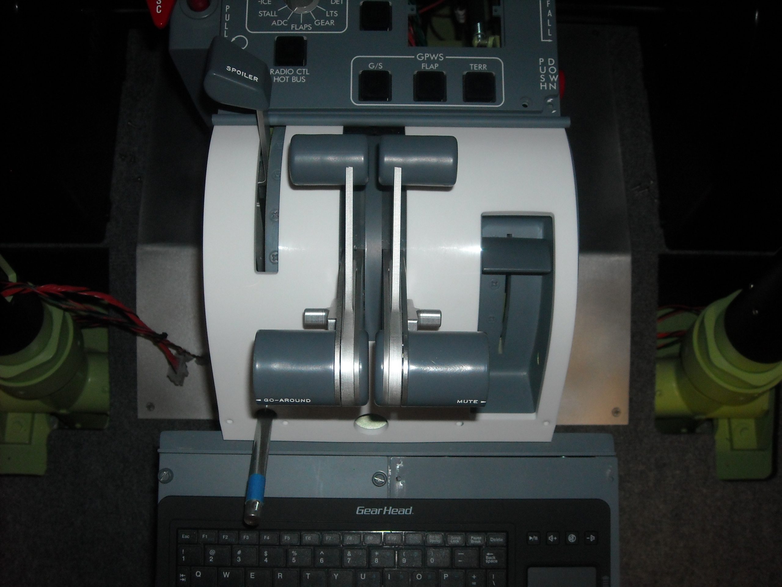
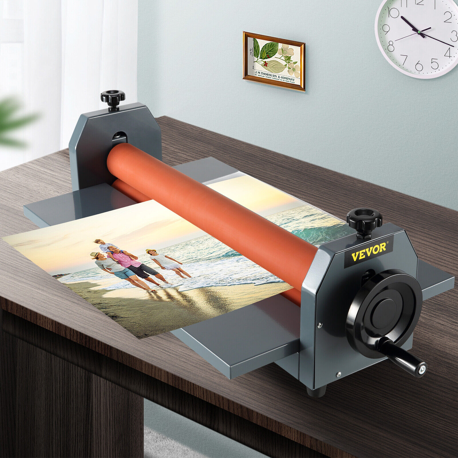
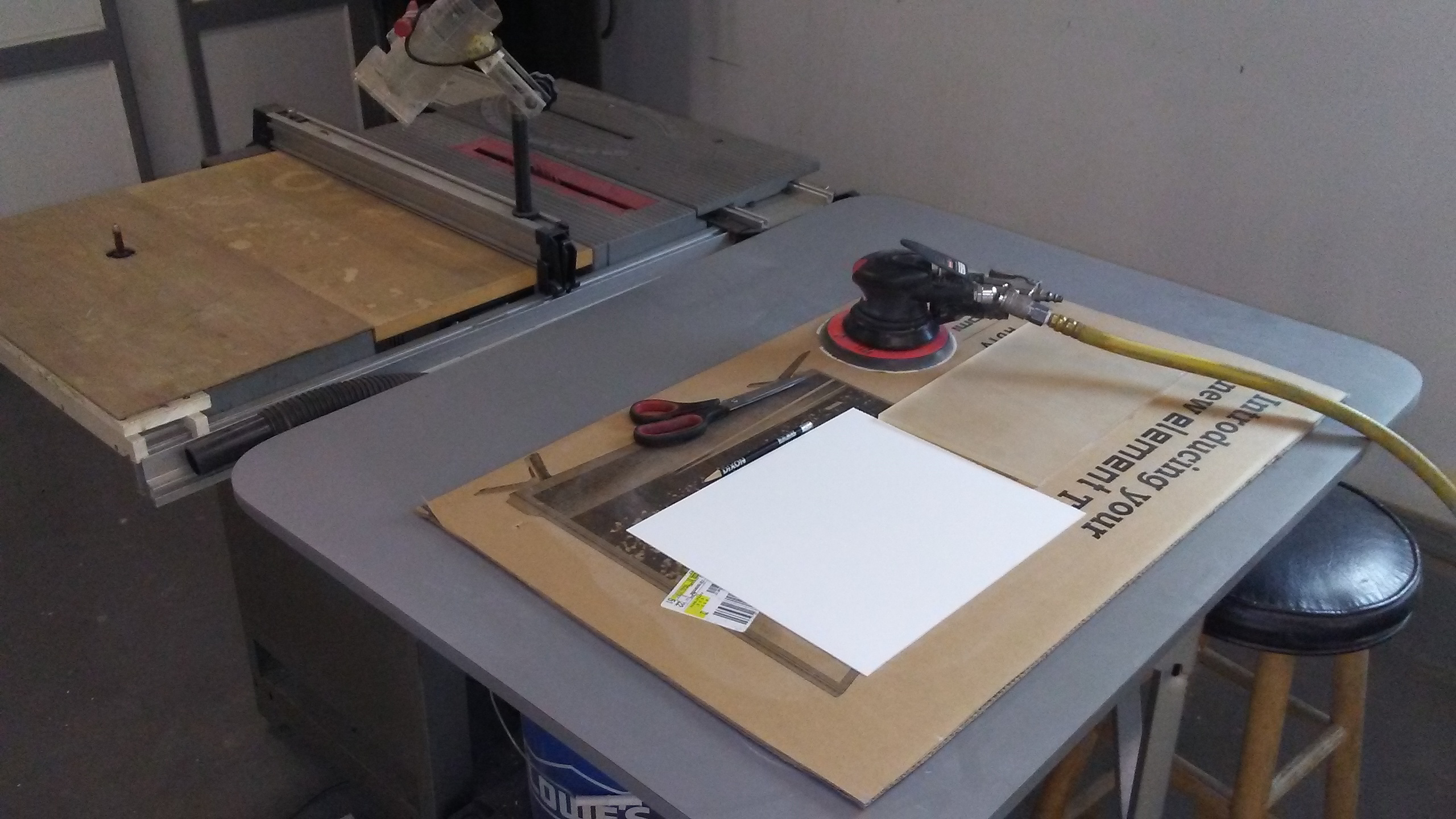
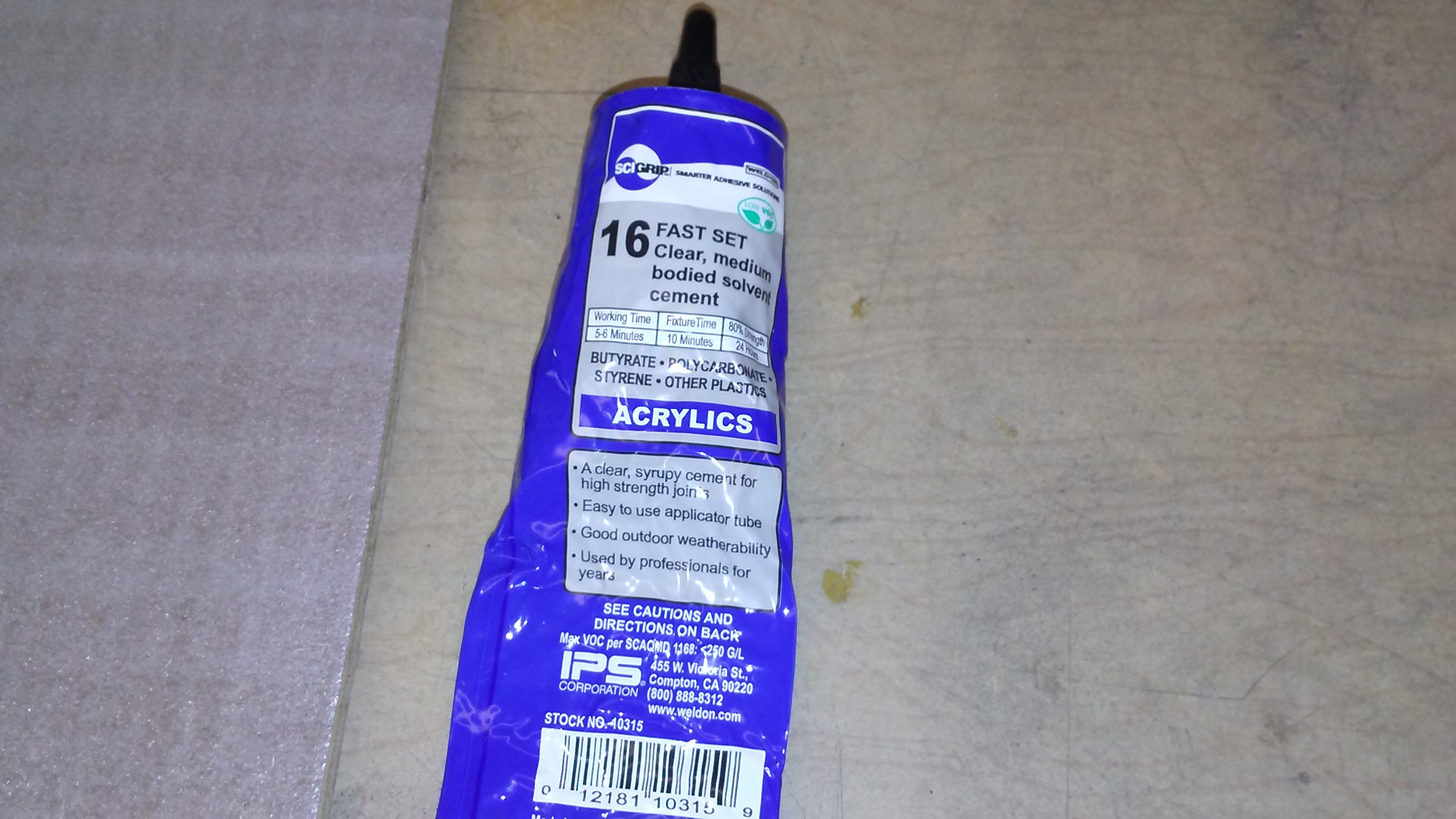
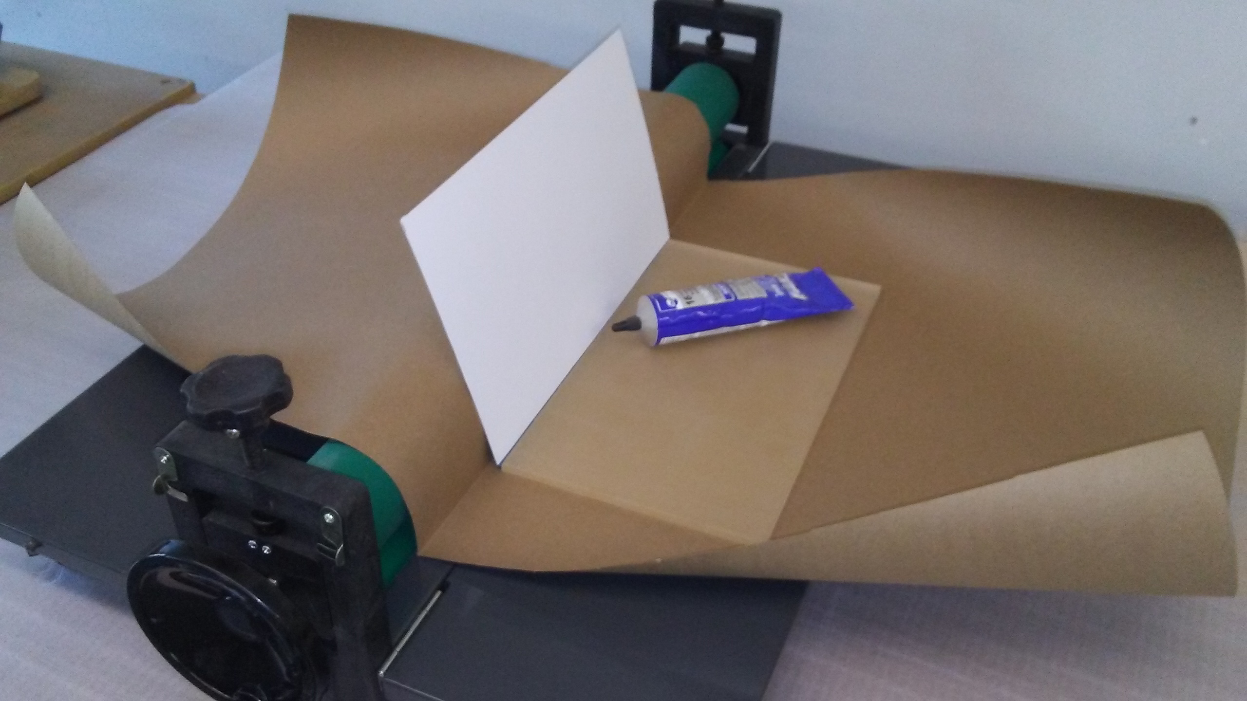
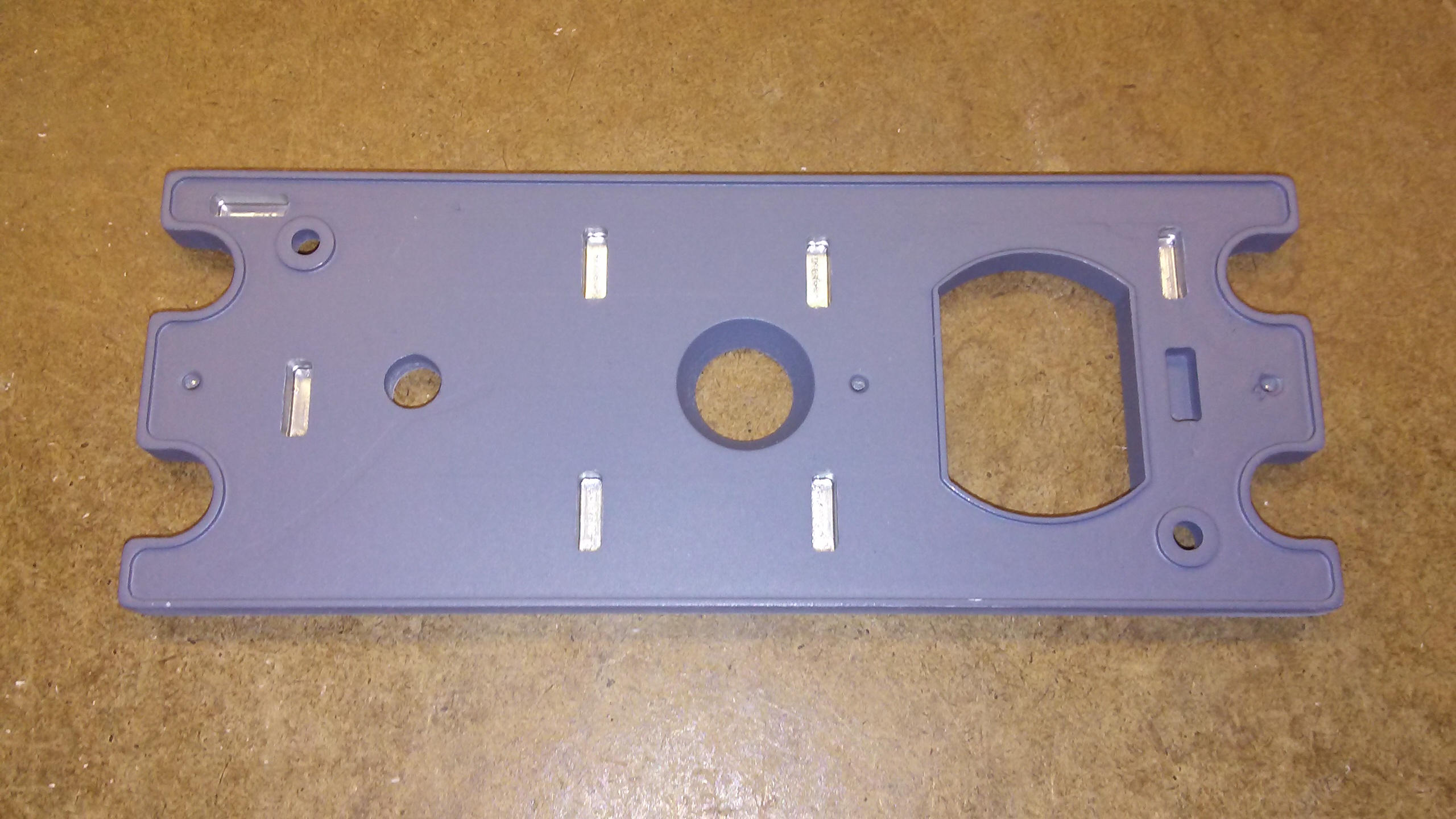
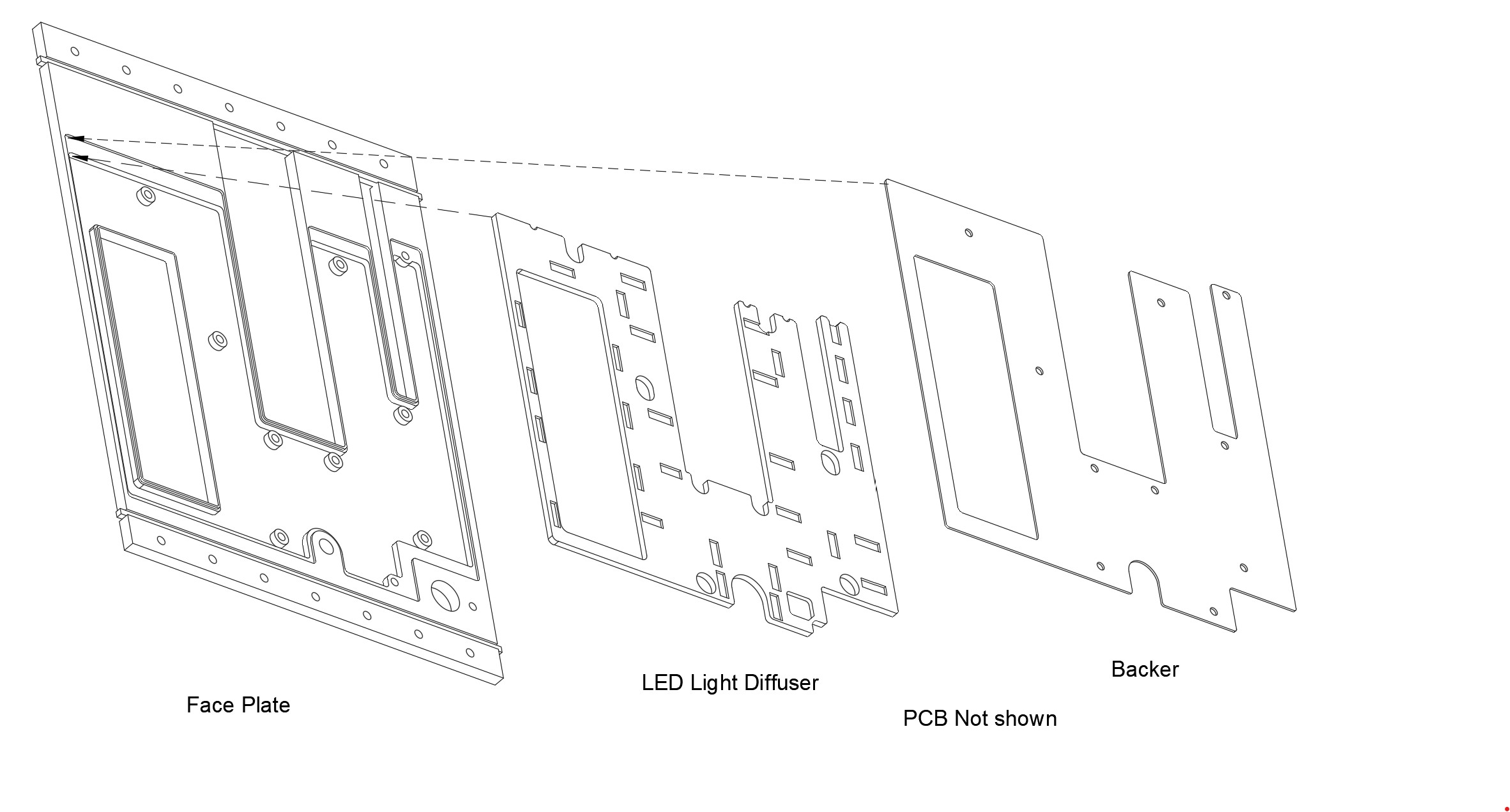
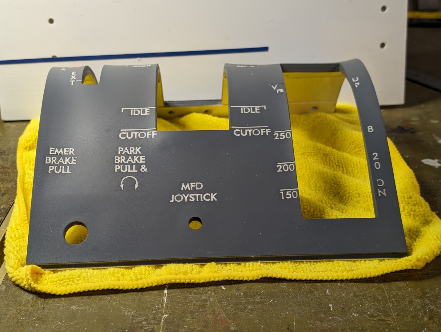
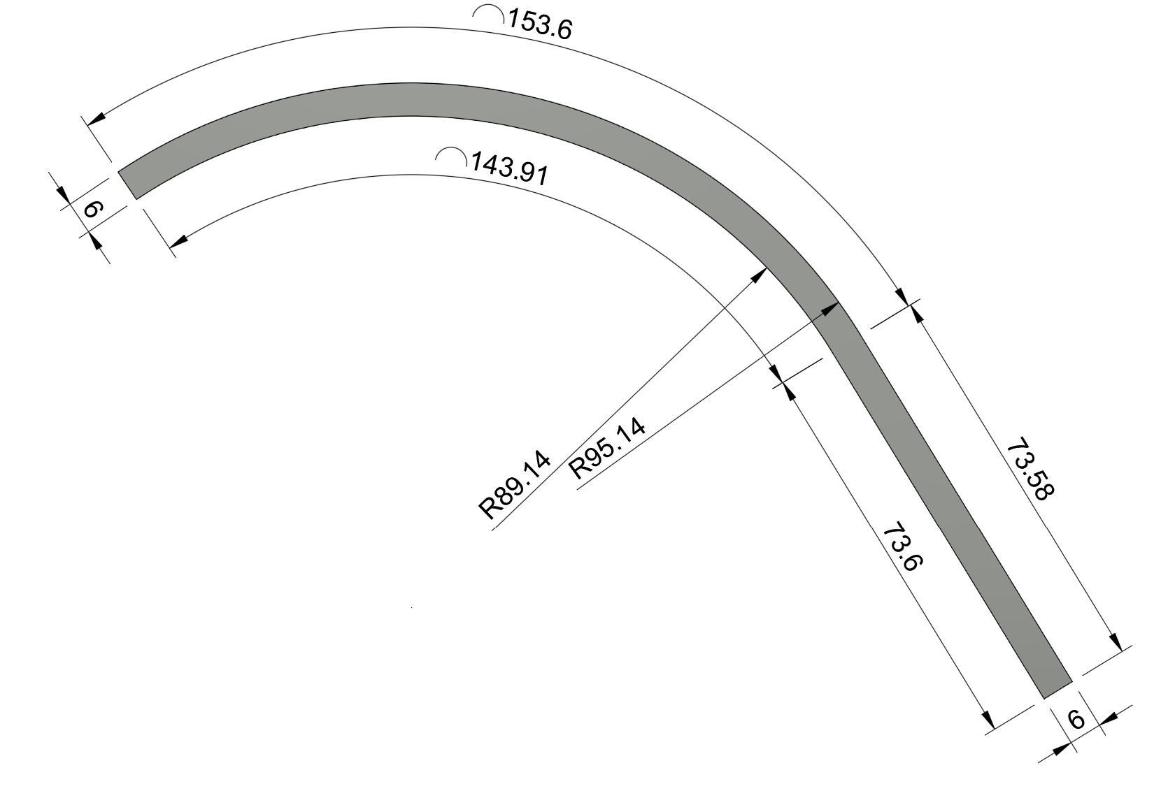
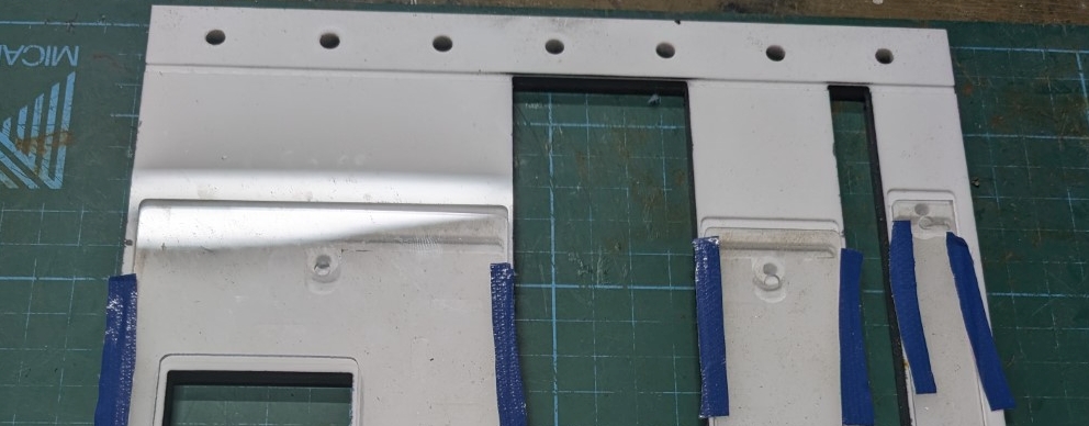
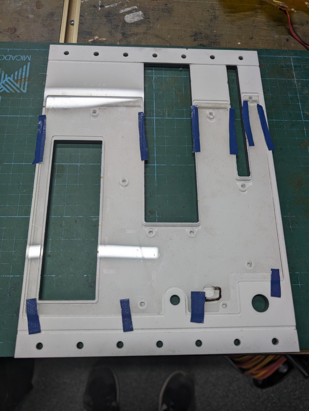
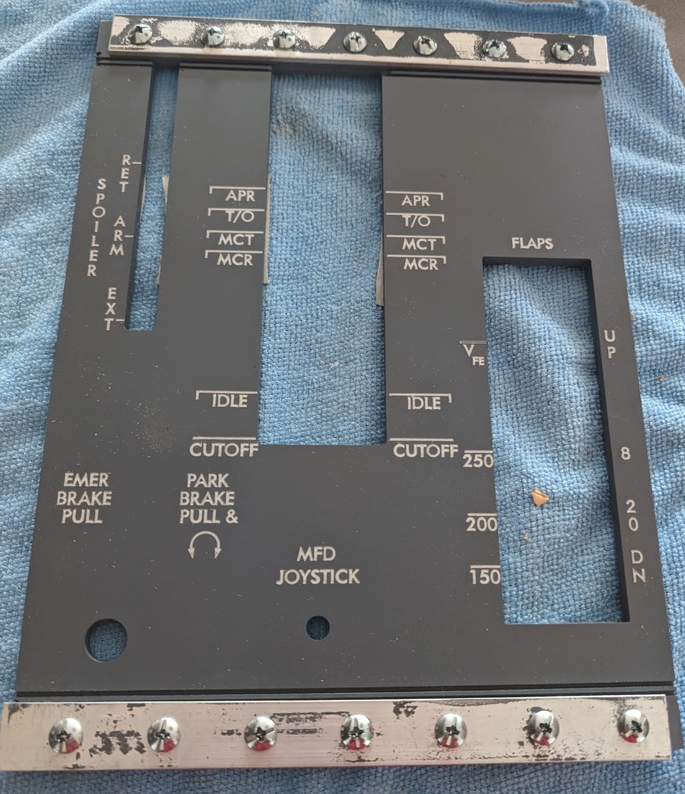
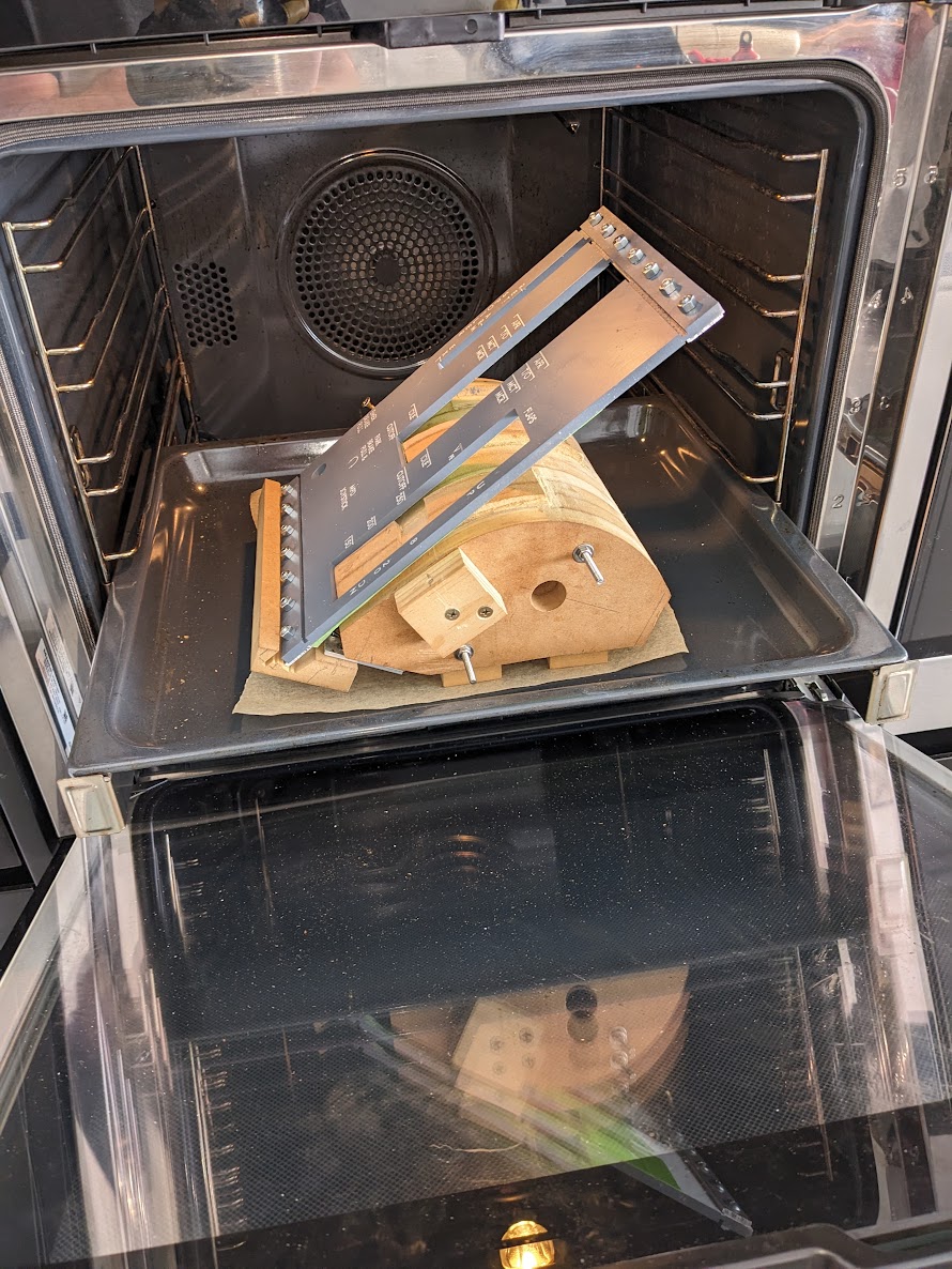
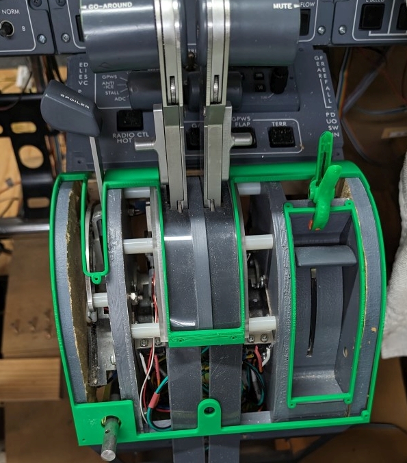
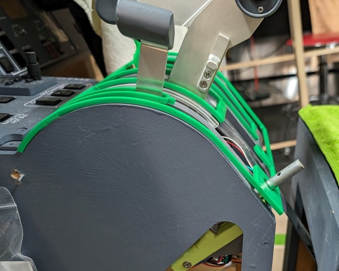
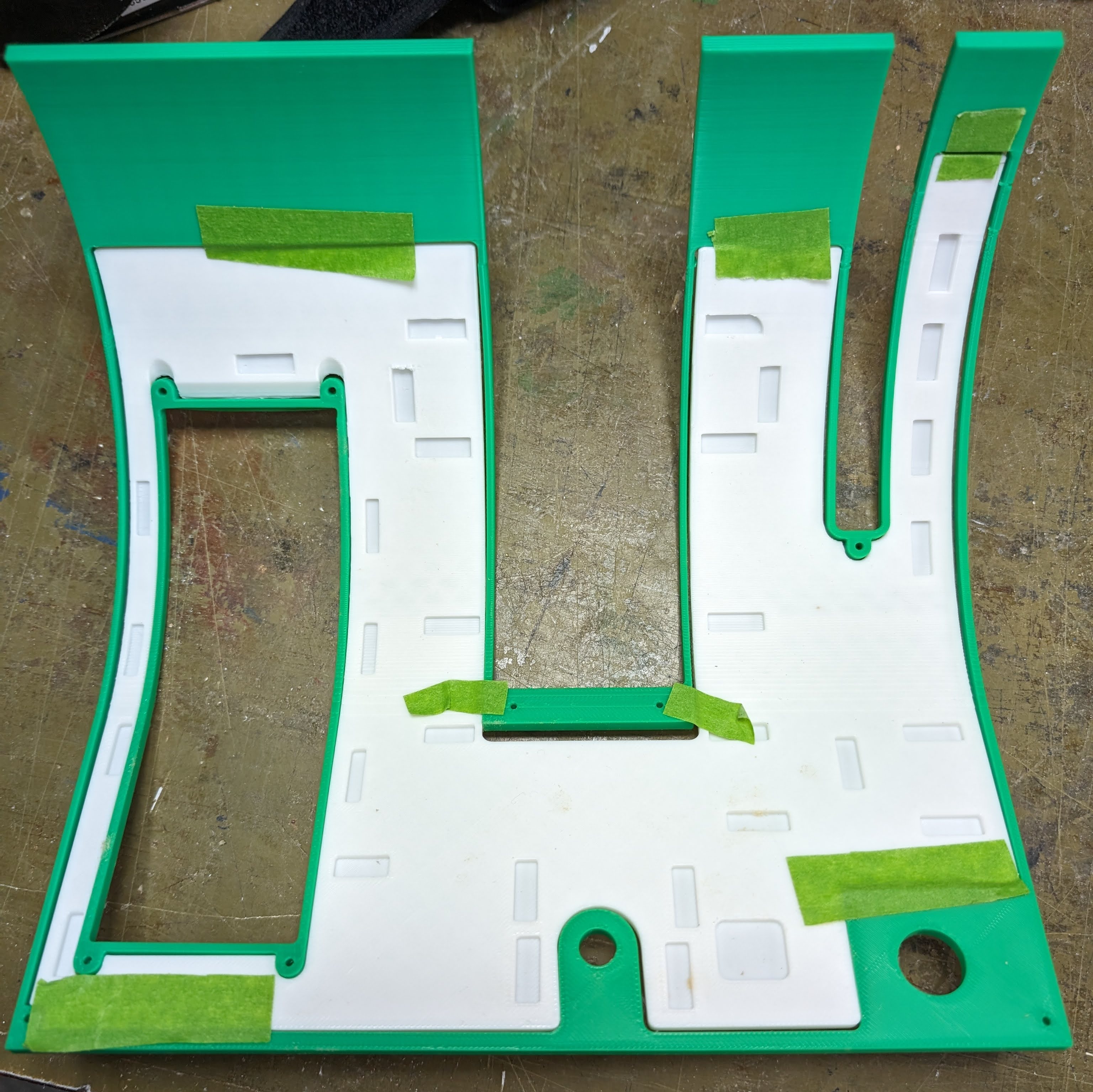
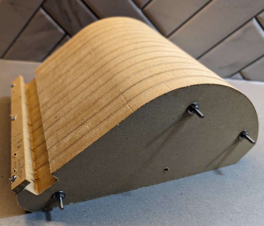
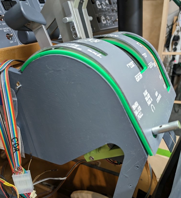
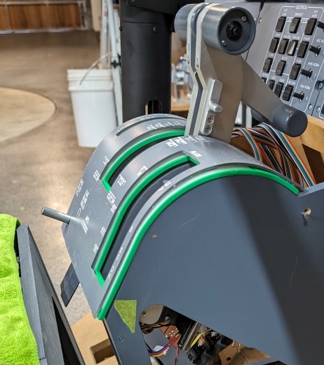
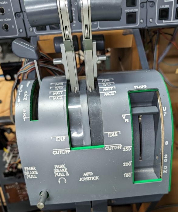
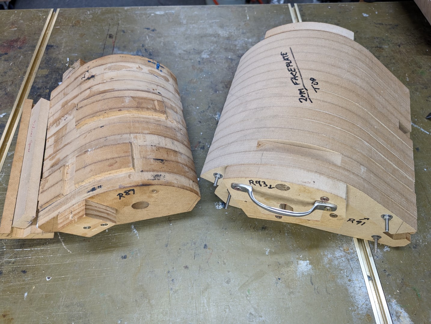
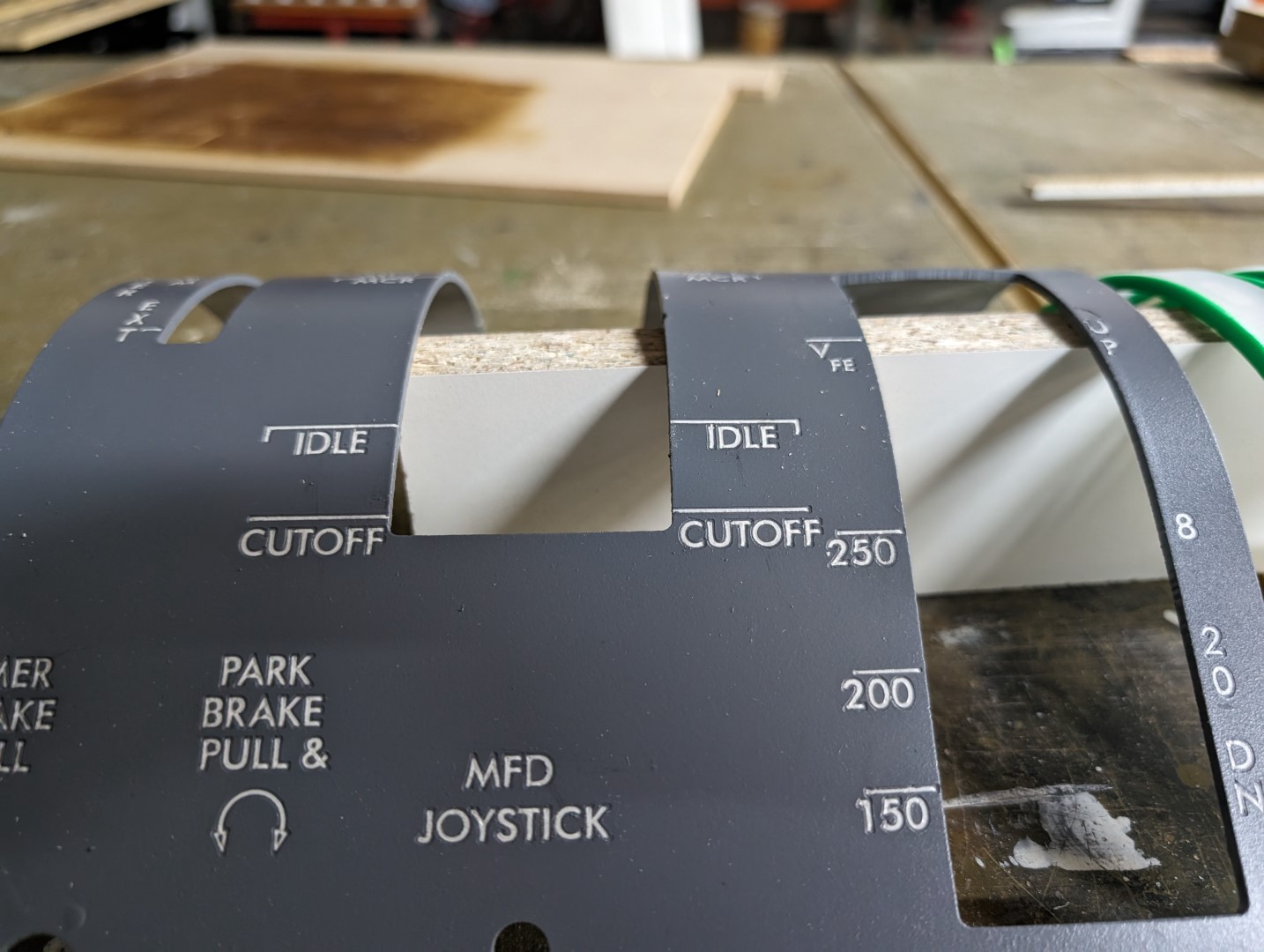
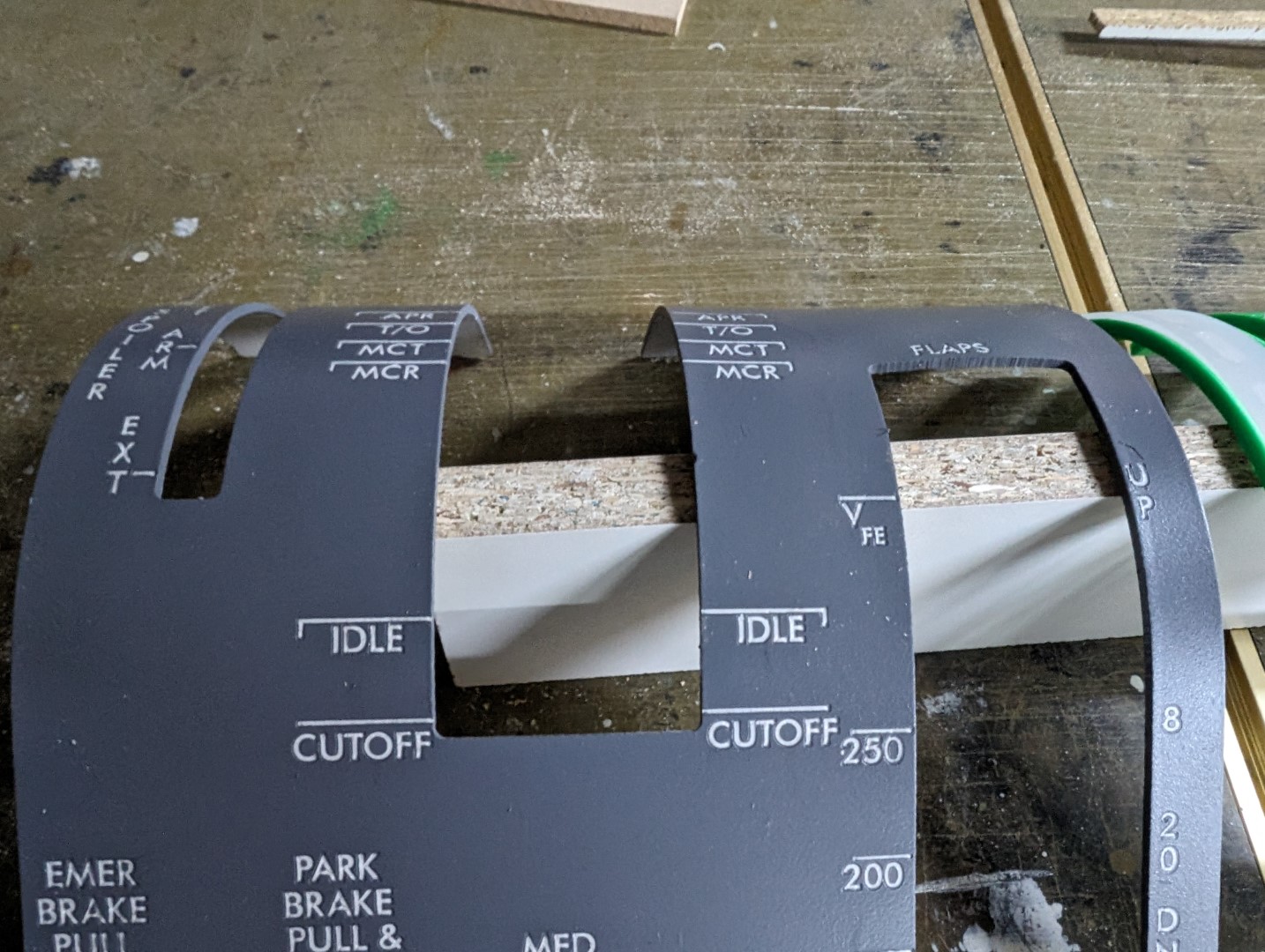
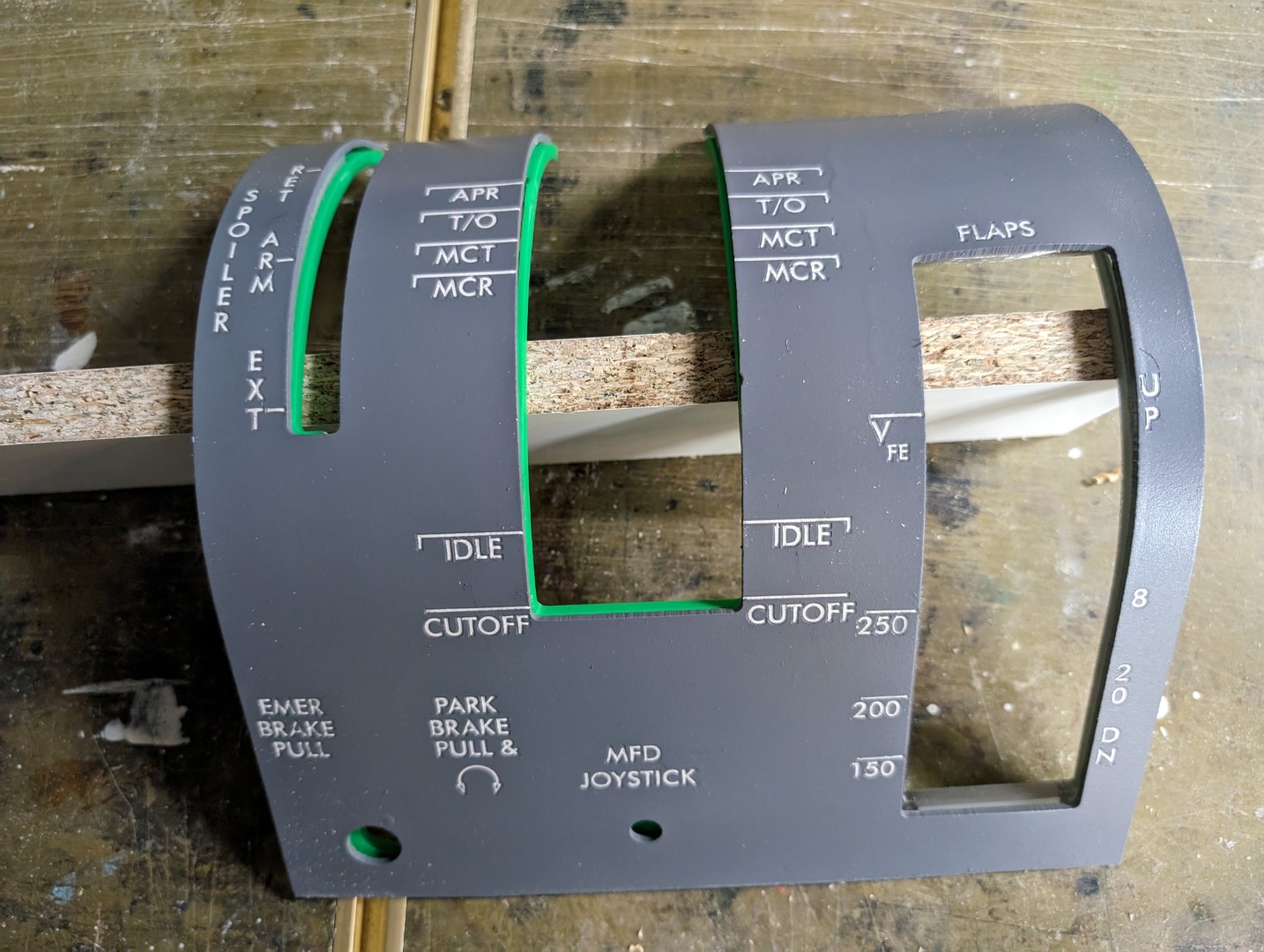
Hey guys, Without a doubt, the TQ curved panel has to be the most difficult of all to make for guys like us with limited tools and techniques available to us. But I suppose this is one of the impressive aspects of a project like this, creating something that is pretty darn cool from nothing while on a shoestring budget relatively speaking. Back several years ago in 2013, (gosh, has it been that long?) I did some research into what it would take to create this unique panel and make it look as good as all the others. I was able to get quit a bit of research and experimenting done but ended up getting sidetracked on other sim projects that were higher priority. Fast forward to the present day, Will Sasse is currently in the middle of trying to crack the code on this most difficult of all panels! To date, he's made some serious progress and has discovered several building techniques that MUST be incorporated into the process. He has several prototype examples but none that he is completely happy with.......yet. This tutorial thread is going to be a little different than other tutorials because as of this date, we still don't have a clear path forward when it comes to techniques and tools needed to achieve the objective. So if you happen to have any really good bad ideas, the forum is open to suggestions! First, let me explain what it is we are trying to do. The Throttle Quadrant panel is the only curved panel in the sim, not counting interior trim panels. See photos. And like all other panels in the Lear45, it is backlit. This example looks a little beat up along the sides which is normal from the pilots kicking and rubbing against it. As you can see, it starts off flat at the bottom and at about 60% of the way up, it starts a gradual curve back down. In the real Lear45, this panel, as a matter of fact, all panels are one solid piece, so bending with a little heat is not that difficult. In all real avionics panel cases, it comes down to engraving the artwork. The most common and typical way to make a aviation light plate panel is as follows: And this is where the wheel come off the bus! We don't have access to a YAG laser. The kind of YAG laser we need is cost prohibitive and no one that has one is willing to take on small jobs like this for us. On the other hand, we do have access to CO2 lasers, but they work much differently than YAG lasers. Without getting too deep in how lasers work, a YAG laser is capable of focusing on certain light wave lengths and leaving other light wave lengths alone. This is how a YAG laser can annihilate darker paint colors while leaving behind without a scratch white colored paint. On the other hand, a CO2 laser is apparently color blind, it just cuts and engraves, the questions is how deep and that depends on how powerful the laser is or what it is set at. I feel I had to explain all that to help explain how we have made making panels more difficult than it really needs to be. A YAG laser would simplify the process and make this curved TQ panel not so much of a problem. So if we can't use a YAG laser, how do we make panels? I won't spell it out as I did above, but the key element is to take a solid piece of .25" cast white plastic and mill it out from the back side, creating a pocket so that a clear piece can insert into the void creating the light pocket. Skipping a head a few step, the CO2 laser or even a cnc engraver comes in and removes material from the top side exposing the white cast plastic. The difference is the CO2 laser or cnc engraver can't stop when it sees a particular paint color, white in this case, it just cuts as deep as you have it set at which can be tricky. Too shallow and you risk leaving gray paint behind. Too deep and you will cut through he thin layer of white cast plastic which on average is about .05" thick. So making FLAT backlit panels with a CO2 laser is not a problem, put as you can see, it is more time consuming, requires more pieces of plastic (internal clear plate) and can be tricky when it comes to engraving the artwork compared to the preferred method. Again, with a YAG laser, intensity is not a factor. Even at full power, it is only looking to annihilate darker colors leaving behind the white colors untouched. Anyone have access to a YAG laser? And this brings us back to the curved TQ panel. Without a YAG laser, we are stuck making panels with a milled out light pocket making the front face of the panel super thin, around .05" thick. This is not a problem when making flat panels, however, to make curved panels, this requires the introduction of heat in an oven.........for several minutes...........at around 325 degrees! What you end up with is a painted, engraved, warped, useless panel with several hours invested in it. Again, if we had access to a YAG laser, we could build the TQ panel in the same manor outlined in steps 1-6 above. Then introduce it to the heating and forming process with a high chance of success. Now that you have a good idea of how the real TQ panel is made and why we can't take that same path, I want to share with you some of the things I have discovered while attempting to find a path forward to complete success. As I mentioned previously, I first started with forming test. The first thing you need if you want to bend something is something to bend it over. This is my TQ panel jig. It consist of eleven .75" pieces of MDF bolted together. I found covering the jig with aluminum foil prevents the MDF particles from sticking to or marring the painted surface of the TQ panel. I started small with a scrap piece of plastic just to see how it reacted to different temperatures. I had to "help" this piece lay down and as you can see, it did not want to conform to the jig fully. This is a test where I have the jig laying back in an attempt to see if our friend "gravity" made a difference. No photo to show, but about the same results, it did not conform to the jig fully. What I determined is the panel needs help, but you can't touch the panel because remember, the panel will be painted and engraved. Touching the surface or even the edges of a painted panel in a 325 degree oven will damage the painted surface. My next idea was to pull it down from the edge with screws. These are small eyelet screws with a picture frame wire running through them. This sorta worked! But some of the screws pulled out of the edge of the plastic in additional test. The solution was to add built in "pull tabs" all the way across the top and bottom of the TQ panel. These pull tabs are milled down to less than half the height of the actual TQ panel. This way the straight edge lines at the top and bottom remain perfect during the forming process. Once formed and cooled, the pull tabs are manually removed with a Drimel tool and hand file. A little careful filing, tape masking and paint should finish off the panel to where it looks correct. This method forms the curved TQ panel while protecting the painted and engraved finish. Here are a few photos of my last test bend that I did in 2013. It's not perfect but it helps prove the lessons learned and techniques applied so far! I feel comfortable that we will be able to achieve success with the forming process........as long as we are bending a solid piece of cast plastic.......but to date, I am only able to produce panels with the back side hollowed out. If I tried to form a hollowed out TQ panel with a thin front face, I don't think I would be able to achieve the same results as what I have above. Have a mentioned how nice it would be to have access to a YAG laser? Hey guys, Without a doubt, the TQ curved panel has to be the most difficult of all to make for guys like us with limited tools and techniques available to us. But I suppose this is one of the impressive aspects of a project like this, creating something that is pretty darn cool from nothing while on a shoestring budget relatively speaking. Back several years ago in 2013, (gosh, has it been that long?) I did some research into what it would take to create this unique panel and make it look as good as all the others. I was able to get quit a bit of research and experimenting done but ended up getting sidetracked on other sim projects that were higher priority. Fast forward to the present day, Will Sasse is currently in the middle of trying to crack the code on this most difficult of all panels! To date, he's made some serious progress and has discovered several building techniques that MUST be incorporated into the process. He has several prototype examples but none that he is completely happy with.......yet. This tutorial thread is going to be a little different than other tutorials because as of this date, we still don't have a clear path forward when it comes to techniques and tools needed to achieve the objective. So if you happen to have any really good bad ideas, the forum is open to suggestions! First, let me explain what it is we are trying to do. The Throttle Quadrant panel is the only curved panel in the sim, not counting interior trim panels. See photos. And like all other panels in the Lear45, it is backlit. This example looks a little beat up along the sides which is normal from the pilots kicking and rubbing against it. As you can see, it starts off flat at the bottom and at about 60% of the way up, it starts a gradual curve back down. In the real Lear45, this panel, as a matter of fact, all panels are one solid piece, so bending with a little heat is not that difficult. In all real avionics panel cases, it comes down to engraving the artwork. The most common and typical way to make a aviation light plate panel is as follows: And this is where the wheel come off the bus! We don't have access to a YAG laser. The kind of YAG laser we need is cost prohibitive and no one that has one is willing to take on small jobs like this for us. On the other hand, we do have access to CO2 lasers, but they work much differently than YAG lasers. Without getting too deep in how lasers work, a YAG laser is capable of focusing on certain light wave lengths and leaving other light wave lengths alone. This is how a YAG laser can annihilate darker paint colors while leaving behind without a scratch white colored paint. On the other hand, a CO2 laser is apparently color blind, it just cuts and engraves, the questions is how deep and that depends on how powerful the laser is or what it is set at. I feel I had to explain all that to help explain how we have made making panels more difficult than it really needs to be. A YAG laser would simplify the process and make this curved TQ panel not so much of a problem. So if we can't use a YAG laser, how do we make panels? I won't spell it out as I did above, but the key element is to take a solid piece of .25" cast white plastic and mill it out from the back side, creating a pocket so that a clear piece can insert into the void creating the light pocket. Skipping a head a few step, the CO2 laser or even a cnc engraver comes in and removes material from the top side exposing the white cast plastic. The difference is the CO2 laser or cnc engraver can't stop when it sees a particular paint color, white in this case, it just cuts as deep as you have it set at which can be tricky. Too shallow and you risk leaving gray paint behind. Too deep and you will cut through he thin layer of white cast plastic which on average is about .05" thick. So making FLAT backlit panels with a CO2 laser is not a problem, put as you can see, it is more time consuming, requires more pieces of plastic (internal clear plate) and can be tricky when it comes to engraving the artwork compared to the preferred method. Again, with a YAG laser, intensity is not a factor. Even at full power, it is only looking to annihilate darker colors leaving behind the white colors untouched. Anyone have access to a YAG laser? And this brings us back to the curved TQ panel. Without a YAG laser, we are stuck making panels with a milled out light pocket making the front face of the panel super thin, around .05" thick. This is not a problem when making flat panels, however, to make curved panels, this requires the introduction of heat in an oven.........for several minutes...........at around 325 degrees! What you end up with is a painted, engraved, warped, useless panel with several hours invested in it. Again, if we had access to a YAG laser, we could build the TQ panel in the same manor outlined in steps 1-6 above. Then introduce it to the heating and forming process with a high chance of success. Now that you have a good idea of how the real TQ panel is made and why we can't take that same path, I want to share with you some of the things I have discovered while attempting to find a path forward to complete success. As I mentioned previously, I first started with forming test. The first thing you need if you want to bend something is something to bend it over. This is my TQ panel jig. It consist of eleven .75" pieces of MDF bolted together. I found covering the jig with aluminum foil prevents the MDF particles from sticking to or marring the painted surface of the TQ panel. I started small with a scrap piece of plastic just to see how it reacted to different temperatures. I had to "help" this piece lay down and as you can see, it did not want to conform to the jig fully. This is a test where I have the jig laying back in an attempt to see if our friend "gravity" made a difference. No photo to show, but about the same results, it did not conform to the jig fully. What I determined is the panel needs help, but you can't touch the panel because remember, the panel will be painted and engraved. Touching the surface or even the edges of a painted panel in a 325 degree oven will damage the painted surface. My next idea was to pull it down from the edge with screws. These are small eyelet screws with a picture frame wire running through them. This sorta worked! But some of the screws pulled out of the edge of the plastic in additional test. The solution was to add built in "pull tabs" all the way across the top and bottom of the TQ panel. These pull tabs are milled down to less than half the height of the actual TQ panel. This way the straight edge lines at the top and bottom remain perfect during the forming process. Once formed and cooled, the pull tabs are manually removed with a Drimel tool and hand file. A little careful filing, tape masking and paint should finish off the panel to where it looks correct. This method forms the curved TQ panel while protecting the painted and engraved finish. Here are a few photos of my last test bend that I did in 2013. It's not perfect but it helps prove the lessons learned and techniques applied so far! I feel comfortable that we will be able to achieve success with the forming process........as long as we are bending a solid piece of cast plastic.......but to date, I am only able to produce panels with the back side hollowed out. If I tried to form a hollowed out TQ panel with a thin front face, I don't think I would be able to achieve the same results as what I have above. Have a mentioned how nice it would be to have access to a YAG laser? My second push to solve the curved TQ panel problem was back in 2019. This time I was looking to purchase or manufacture a piece of plastic that is solid, has a thin white cast layer on top with a solid thicker clear cast piece on the back side. Basically I hybrid piece of cast plastic. Of course what we need no one makes! I was hopeful that I could find stock white cast plastic that was only .0313" to .05" thick, but the only examples I could find don't transmit light very well if at all. But I did do some testing and made a couple sample pieces, although failing the light test. The key to this part of the solution is picking up one of these. It's a Cold Laminator Manual Roller Machine for vinyl photo film, laminating or lesser known projects, making Learjet45 curved Throttle Quadrant covers. This one is about $82 free shipping. Here I have .0313" thick white plastic and .23" (give or take .01") cast clear plastic. The sides that are going to face each other have been orbital sanded to created a super strong bond. It should be noted the white thin plastic in the sample test did not pass the light test. No one makes #3015 or #7508 white cast plastic that is thinner than .0125". My future attempts will require milling down a piece of .125" thick white cast plastic to about .045". It can be done, just time consuming. After trimming the two piece to roughly match each other, I taped them together like a book binding. Just a bead of Acrylic cement is needed in the fold. You have to use Acrylic cement like this: Simply apply a bead of cement in the fold and close the top over. You will also need to wrap the two pieces in thick construction paper to protect your rollers from the Acrylic cement. I should mention that before you roll the pieces through, do a couple test rolls without any cement to make sure the height settings for the rollers are correct. You want the pieces to fit snug as they roll through. This is about the only time you will see a set of weights in my hands! Weigh the now one single piece down on a solid flat surface. You may not need to do this but I do it for about 15 minutes to be sure the bond is solid. And here it is, a solid piece a hybrid stock plastic. The white cap in this case is .0313" thick and the clear cast plastic is .23" thick. The pieces that I will end up making for the TQ Cover panel will be made of .045" thick white cast either #7508 or #3015 and .23" thick clear cast plastic. When I was testing this method of panel building I used the Pitch Trim Panel as my sample piece. This method of making panels can be applied to all panels in the Lear45 including the curved TQ panel. The problem with making this hybrid plastic stock is it's more time consuming than the alternative way. Therefore, I have decided to use this method only in cases where we have no choice. It might be hard to see at first glance but if you look closely, you can see the top cap is white plastic followed by the clear cast behind it. One thing for sure is the solid panel construction is way stronger than the pocketing method. It looks cool too! This is the back side of the panel with the clad pocket cut in place, including pockets for the LEDs and resistors. I also have the bottoms of the LED pockets painted silver to help prevent light bleed and to also reflect light back into the panel which creates better light spread. In conclusion, what we have here is a SOLID panel that has a built in light chamber, the front face is white plastic (Cast White plastic in the future), is now CO2 laser friendly and last but not least, will hold up in the oven at 325 degrees for a few minutes! For guys like us with limited tools and techniques at our disposal, in my opinion, this is the only path forward in creating a quality TQ curved panel. As I mention at the beginning of this post, Will is in the process of pushing this panel puzzle forward. He has already discovered and solved several issue, one being that when you bend two pieces over a form, one being the front panel and the other the copper clad, by the time the bend stops at the top edge, the clad edge is longer than the front panel. Enough that this discrepancy has to be accounted for and corrected in the dxf drawing. Which reminds me, I have attached the TQ Cover Panel Master.dxf HERE That discrepancy has not yet been drawn into my drawing, so be mindful of that if you are eager to take this part of the project on. I am actually looking forward to starting back up on this project and finishing it, especially with all the new skills and tools I have acquired over the past ten years. Unfortunately, one of those tools is NOT the YAG laser, however, I did pick up a professional CO2 laser earlier this year and we do have a tentative path to success! Last point, I said this in the opening in the first post, this is the most difficult and challenging panel of this build. I hope these posts helps shed some light on why I say that. If you have any thoughts or ideas to contribute to this part of the project please share! Soon you will be hearing from Will and what he has learned first hand. My second push to solve the curved TQ panel problem was back in 2019. This time I was looking to purchase or manufacture a piece of plastic that is solid, has a thin white cast layer on top with a solid thicker clear cast piece on the back side. Basically I hybrid piece of cast plastic. Of course what we need no one makes! I was hopeful that I could find stock white cast plastic that was only .0313" to .05" thick, but the only examples I could find don't transmit light very well if at all. But I did do some testing and made a couple sample pieces, although failing the light test. The key to this part of the solution is picking up one of these. It's a Cold Laminator Manual Roller Machine for vinyl photo film, laminating or lesser known projects, making Learjet45 curved Throttle Quadrant covers. This one is about $82 free shipping. Here I have .0313" thick white plastic and .23" (give or take .01") cast clear plastic. The sides that are going to face each other have been orbital sanded to created a super strong bond. It should be noted the white thin plastic in the sample test did not pass the light test. No one makes #3015 or #7508 white cast plastic that is thinner than .0125". My future attempts will require milling down a piece of .125" thick white cast plastic to about .045". It can be done, just time consuming. After trimming the two piece to roughly match each other, I taped them together like a book binding. Just a bead of Acrylic cement is needed in the fold. You have to use Acrylic cement like this: Simply apply a bead of cement in the fold and close the top over. You will also need to wrap the two pieces in thick construction paper to protect your rollers from the Acrylic cement. I should mention that before you roll the pieces through, do a couple test rolls without any cement to make sure the height settings for the rollers are correct. You want the pieces to fit snug as they roll through. This is about the only time you will see a set of weights in my hands! Weigh the now one single piece down on a solid flat surface. You may not need to do this but I do it for about 15 minutes to be sure the bond is solid. And here it is, a solid piece a hybrid stock plastic. The white cap in this case is .0313" thick and the clear cast plastic is .23" thick. The pieces that I will end up making for the TQ Cover panel will be made of .045" thick white cast either #7508 or #3015 and .23" thick clear cast plastic. When I was testing this method of panel building I used the Pitch Trim Panel as my sample piece. This method of making panels can be applied to all panels in the Lear45 including the curved TQ panel. The problem with making this hybrid plastic stock is it's more time consuming than the alternative way. Therefore, I have decided to use this method only in cases where we have no choice. It might be hard to see at first glance but if you look closely, you can see the top cap is white plastic followed by the clear cast behind it. One thing for sure is the solid panel construction is way stronger than the pocketing method. It looks cool too! This is the back side of the panel with the clad pocket cut in place, including pockets for the LEDs and resistors. I also have the bottoms of the LED pockets painted silver to help prevent light bleed and to also reflect light back into the panel which creates better light spread. In conclusion, what we have here is a SOLID panel that has a built in light chamber, the front face is white plastic (Cast White plastic in the future), is now CO2 laser friendly and last but not least, will hold up in the oven at 325 degrees for a few minutes! For guys like us with limited tools and techniques at our disposal, in my opinion, this is the only path forward in creating a quality TQ curved panel. As I mention at the beginning of this post, Will is in the process of pushing this panel puzzle forward. He has already discovered and solved several issue, one being that when you bend two pieces over a form, one being the front panel and the other the copper clad, by the time the bend stops at the top edge, the clad edge is longer than the front panel. Enough that this discrepancy has to be accounted for and corrected in the dxf drawing. Which reminds me, I have attached the TQ Cover Panel Master.dxf HERE That discrepancy has not yet been drawn into my drawing, so be mindful of that if you are eager to take this part of the project on. I am actually looking forward to starting back up on this project and finishing it, especially with all the new skills and tools I have acquired over the past ten years. Unfortunately, one of those tools is NOT the YAG laser, however, I did pick up a professional CO2 laser earlier this year and we do have a tentative path to success! Last point, I said this in the opening in the first post, this is the most difficult and challenging panel of this build. I hope these posts helps shed some light on why I say that. If you have any thoughts or ideas to contribute to this part of the project please share! Soon you will be hearing from Will and what he has learned first hand. Thanks for the kick-off Ron, all good info. Yes, I am attempting to create the TQ Face Plate. It is not simple. I will tell you what I’m up to now and provide a full report when I am successful (hopefully soon!) At this point I do not want to make a glued together plate as Ron suggests. I hope it can be done using a single 6mm white acrylic as the prime material. Currently I am building the panel using 4 components: the face plate (6mm white acrylic); a light diffusing plate (3mm LED acrylic; a 0.11mm flexible PCB; and a 1 mm polycarbonate backer. The 6mm face acrylic has a 4.2mm recess machined into the back side to enable the other 3 pieces to nest inside. The light plate has 1.2mm deep slots for the LED’s and resistors soldered to the pcb. The stack is held together by M2.5 x 4mm countersunk machine screws from the backer to threaded inserts mounted on the face plate. I have been working on thermoforming a complete stack (without the PCB) in the belief that a fully supported face plate shouldn’t sag, and that this would give me 3 pieces that fit together cleanly. That would be fine except for… …thermoforming temperatures. Acrylic deforms at 140°C to 160°C (280°F - 320°F) and polycarb deforms at 180°C to 260°C (300°F - 500°F). I found that even the 1 mm polycarb needed a minimum 200°C to deform which was way too much for the acrylic. I don’t have the numbers for the LED acrylic but it seems to deform at 140°C-160°C range. Because the polycarb is at the bottom of the stack it prevents the acrylics deforming when they want to so they sag and warp. My thinking is that next time I will make a sacrificial backer from 2mm acrylic ( I can’t get 1 mm acrylic) wIth a light plate so at least I am working the same material. The polycarb is flexible enough to be fitted cold should I need to. The other interesting design consideration is ‘creepage’, the ratio of top surface to bottom surface changes due to adding curvature. In this case I calculated that the ratio of the curved part of the face plate is about 0.93:1. That is the bottom surface is 0.93%as long as the top surface. This affects the diffuser and the backer in the curved section which starts at about 73mm up from the lower edge. During the design phase in 3D cad I took the distance of the feature was above the 73mm line and subtracted 7%. These pieces also needed to fit the unbent face plate so gaps and slots were made depending on distance from the 73mm line. The lower 73mm is flat and retained a 1:! ratio. The stack going into the oven looks like this: Note the gaps between the clear backer and the end of the cutout. You can also see the diffuser shorter than its cutout and the slots to allow the threaded inserts stands to creep down during thermoforming. The distance of the setback in this photo proved to be too short. I am almost doubling it in the next attempt. You can also see I continued Ron’s ‘flanges’ to stabilize the face plate during thermoforming by bolting on a piece of 20mm x 3mm aluminium with seven 5mm bolts and nuts. I added a gutter at the top and bottom of the TQ, 2.0 mm deep on the front face and 1.0mm on the back face of the face plate. This allows a simple snap removal of the flange after thermoforming – place flange in a vise and give the face plate a short sharp tap and they separate cleanly. Clean up with sandpaper and paint. I used a 2mm flat end mill to create these as that is my tool of choice for most operations - minimise wastage on line cuts. It would be cleaner to use a low angle pointed engraving tool for a more accurate snap line. If I had a quick tool change system I would do this… but I don’t! Although I will probably give it a go on the next attempt. This is what the stack looks like just before thermoforming. The back without the 20x3mm stabilizing strip: And the front with the stabilizing strip bolted on: and then in the oven: I will try the 2mm sacrificial backer now and come back to this thread.. This has been 12 months of (very) part time effort. I feel I am closing in on the solution. If/When I do succeed (or give up!) I will write up a bit more comprehensive report. In the meantime If anyone has experience or knowledge of this process please share here. Thanks for the kick-off Ron, all good info. Yes, I am attempting to create the TQ Face Plate. It is not simple. I will tell you what I’m up to now and provide a full report when I am successful (hopefully soon!) At this point I do not want to make a glued together plate as Ron suggests. I hope it can be done using a single 6mm white acrylic as the prime material. Currently I am building the panel using 4 components: the face plate (6mm white acrylic); a light diffusing plate (3mm LED acrylic; a 0.11mm flexible PCB; and a 1 mm polycarbonate backer. The 6mm face acrylic has a 4.2mm recess machined into the back side to enable the other 3 pieces to nest inside. The light plate has 1.2mm deep slots for the LED’s and resistors soldered to the pcb. The stack is held together by M2.5 x 4mm countersunk machine screws from the backer to threaded inserts mounted on the face plate. I have been working on thermoforming a complete stack (without the PCB) in the belief that a fully supported face plate shouldn’t sag, and that this would give me 3 pieces that fit together cleanly. That would be fine except for… …thermoforming temperatures. Acrylic deforms at 140°C to 160°C (280°F - 320°F) and polycarb deforms at 180°C to 260°C (300°F - 500°F). I found that even the 1 mm polycarb needed a minimum 200°C to deform which was way too much for the acrylic. I don’t have the numbers for the LED acrylic but it seems to deform at 140°C-160°C range. Because the polycarb is at the bottom of the stack it prevents the acrylics deforming when they want to so they sag and warp. My thinking is that next time I will make a sacrificial backer from 2mm acrylic ( I can’t get 1 mm acrylic) wIth a light plate so at least I am working the same material. The polycarb is flexible enough to be fitted cold should I need to. The other interesting design consideration is ‘creepage’, the ratio of top surface to bottom surface changes due to adding curvature. In this case I calculated that the ratio of the curved part of the face plate is about 0.93:1. That is the bottom surface is 0.93%as long as the top surface. This affects the diffuser and the backer in the curved section which starts at about 73mm up from the lower edge. During the design phase in 3D cad I took the distance of the feature was above the 73mm line and subtracted 7%. These pieces also needed to fit the unbent face plate so gaps and slots were made depending on distance from the 73mm line. The lower 73mm is flat and retained a 1:! ratio. The stack going into the oven looks like this: Note the gaps between the clear backer and the end of the cutout. You can also see the diffuser shorter than its cutout and the slots to allow the threaded inserts stands to creep down during thermoforming. The distance of the setback in this photo proved to be too short. I am almost doubling it in the next attempt. You can also see I continued Ron’s ‘flanges’ to stabilize the face plate during thermoforming by bolting on a piece of 20mm x 3mm aluminium with seven 5mm bolts and nuts. I added a gutter at the top and bottom of the TQ, 2.0 mm deep on the front face and 1.0mm on the back face of the face plate. This allows a simple snap removal of the flange after thermoforming – place flange in a vise and give the face plate a short sharp tap and they separate cleanly. Clean up with sandpaper and paint. I used a 2mm flat end mill to create these as that is my tool of choice for most operations - minimise wastage on line cuts. It would be cleaner to use a low angle pointed engraving tool for a more accurate snap line. If I had a quick tool change system I would do this… but I don’t! Although I will probably give it a go on the next attempt. This is what the stack looks like just before thermoforming. The back without the 20x3mm stabilizing strip: And the front with the stabilizing strip bolted on: and then in the oven: I will try the 2mm sacrificial backer now and come back to this thread.. This has been 12 months of (very) part time effort. I feel I am closing in on the solution. If/When I do succeed (or give up!) I will write up a bit more comprehensive report. In the meantime If anyone has experience or knowledge of this process please share here. Hi Folks, I had an interesting thought… Since I got a 3D printer (a Bambu Labs X1-C,) I have been rethinking how to create all manner of things, this was high on the list. I could not get past the issue of the milled out 6mm sagging where it was thinner, distorting the faceplate. So have taken Rons idea of an ultra thin finish piece (with paint and text engraved on it) and added a twist, I thought to split the 6mm sheet in two, a 2mm faceplate and a separate 4mm frame. The Led diffuser would sit inside this frame and the PCB and backer behind. The 2mm faceplate would be made the traditional way - mill/paint/etch/thermoform. The 4mm frame would be 3D printed complete, with curves ready to fit. A bit of time with Fusion 360’s sheet metal abilities and I had converted flat drawings into the curved pieces that we require. Push it through 3D printer slicing program, print, clean of the printing supports, and this is what I got… A perfect fit! That was easy I thought, maybe I could print the led diffuser which fits inside the frame. I allowed 0.5mm offset from the inside of the frame for the dimensions of the diffuser, sent it to the printer and it came out a perfect fit to the frame. I printed both these using PLA Basic filament. I’m going to try PETG next time The tricky part of this approach is lining up the faceplate with the frame for gluing. I haven’t decided how to best do this yet. It may be simpler to glue in the diffuser at the same time to provide some structural rigidity to the frame. The other problem is finding a glue that works on PLA. I tried some CA glues that I have on hand, all failed.. I found on the interweb that Gorilla Super Glue works.. Have tried both the gel and the liquid and so far so good. The only thing I had to change from my earlier attempts was the thermoform buck. I tried using the original buck but the radius was too tight and the 2mm acrylic once formed would not relax into the desired 4mm larger radius. This time I kept the buck simple, one surface – 14 pieces cut from 16mm MDF bolted together with M4 threaded rod. The notch at the bottom is to allow for the heads of bolts attaching the aluminium bar to the flange of the faceplate as mentioned in my earlier post, with a flat strip of wood over the base of the notch to hold the flat acrylic in position during heating. I have also made a test 2mm faceplate using the new buck. It fitted the printed pieces like a glove And… the money shot…. Very little sagging or distortion (please excuse the engraving, I miss-set a parameter for post processing and my laser looks like it is due for a lens clean). I will finesse the widths to fit a bit better too. A parting thought, the BambuLab X1-C has a multi spool holder which allows multi colour prints. Perhaps we could print the faceplate as a single item. I think getting crisp text would be difficult, but what do I know? I am only a newby whose thinking is not impeded by knowing what can or can’t be done! That’s all for now… Hi Folks, I had an interesting thought… Since I got a 3D printer (a Bambu Labs X1-C,) I have been rethinking how to create all manner of things, this was high on the list. I could not get past the issue of the milled out 6mm sagging where it was thinner, distorting the faceplate. So have taken Rons idea of an ultra thin finish piece (with paint and text engraved on it) and added a twist, I thought to split the 6mm sheet in two, a 2mm faceplate and a separate 4mm frame. The Led diffuser would sit inside this frame and the PCB and backer behind. The 2mm faceplate would be made the traditional way - mill/paint/etch/thermoform. The 4mm frame would be 3D printed complete, with curves ready to fit. A bit of time with Fusion 360’s sheet metal abilities and I had converted flat drawings into the curved pieces that we require. Push it through 3D printer slicing program, print, clean of the printing supports, and this is what I got… A perfect fit! That was easy I thought, maybe I could print the led diffuser which fits inside the frame. I allowed 0.5mm offset from the inside of the frame for the dimensions of the diffuser, sent it to the printer and it came out a perfect fit to the frame. I printed both these using PLA Basic filament. I’m going to try PETG next time The tricky part of this approach is lining up the faceplate with the frame for gluing. I haven’t decided how to best do this yet. It may be simpler to glue in the diffuser at the same time to provide some structural rigidity to the frame. The other problem is finding a glue that works on PLA. I tried some CA glues that I have on hand, all failed.. I found on the interweb that Gorilla Super Glue works.. Have tried both the gel and the liquid and so far so good. The only thing I had to change from my earlier attempts was the thermoform buck. I tried using the original buck but the radius was too tight and the 2mm acrylic once formed would not relax into the desired 4mm larger radius. This time I kept the buck simple, one surface – 14 pieces cut from 16mm MDF bolted together with M4 threaded rod. The notch at the bottom is to allow for the heads of bolts attaching the aluminium bar to the flange of the faceplate as mentioned in my earlier post, with a flat strip of wood over the base of the notch to hold the flat acrylic in position during heating. I have also made a test 2mm faceplate using the new buck. It fitted the printed pieces like a glove And… the money shot…. Very little sagging or distortion (please excuse the engraving, I miss-set a parameter for post processing and my laser looks like it is due for a lens clean). I will finesse the widths to fit a bit better too. A parting thought, the BambuLab X1-C has a multi spool holder which allows multi colour prints. Perhaps we could print the faceplate as a single item. I think getting crisp text would be difficult, but what do I know? I am only a newby whose thinking is not impeded by knowing what can or can’t be done! That’s all for now… Hi folks. Thought someone out there may be interested. I have just finished testing what has (at least for me!) been a “truth” until now, that is we should not place any thing on the painted surface during thermoforming as it will damage the paintwork. The aluminium stabilising bars I use bear witness to that truth, they have grey paint on them from multiple use. But, they are applied before heating occurs and stay on during heating. I pondered whether the application of an upper female former after heating would have the same result? Photo of the aluminium stabilising bars: Up till now I have been very careful not to touch the painted surface until it has cooled down. I have in the past left imprints of the oven gloves that I used to use (I now use mechanics leather gloves, smooth, no texture). Knowing in this case the pressure from a thumb per square inch is much more than a large block of wood spread over the whole plate, I thought it would be interesting to test it. So I did. I built a new former for the 2mm face plate, again 14 pieces of 16mm MDF bolted together with three 4mm threaded rods. This time I made a lower (male) form and an upper (female) form. The working surface of the male form has a curvature radius of 93mm, and the matching surface of the female form has a radius of 95mm. The 2mm difference allows the 2 mm faceplate to be sandwiched precisely between the two. I applied no finish to either surface, they were plain MDf edges. I did my best to align them smoothly, I did not sand the surfaces, they were left as they came off the CNC. For reference the curvature of the timber TQ pedestal furniture is 89.1416mm radius I also added locating fingers and slots to either end to ensure correct alignment of the two parts. I set these for a tight fit without the 2mm faceplate so that when applied with the 2mm plate there is a little bit of wiggle room Fully closed, nothing in between: with 2mm faceplate in between. Notice gap between is consistent: open: According to the instruction on a can of Rustoleum, the spray paint we use can take can take up to 7 days to fully cure on plastic. Wanting to test the worst case I cut the panel and spray painted 3 coats on the faceplate on day 1 following the advice on the can re re-coats (20min to 60min between coats). I left it for 24 hours then laser engraved the markings and headed straight to the oven. The faceplate was placed on the lower form and heated at 160°C until the large area below the spoilers slot relaxed onto the form, this took about 8 minutes. Then I slid the lower form and plate out to the front to the oven and placed the upper form on top. The upper form was not preheated, it was room temperature. I immediately moved the whole lot out of the oven onto a bench. To do this I gripped the forms at both ends gently squeezing the upper and lower form together at the same time to make sure the panel was flat. Left it for a couple of minutes and lifted the upper form off and bingo! One very flat panel with no damage to the painted surface. Fix everything in place with a couple of coats of clear and I had an almost perfect start to a TQ panel! Here is a photo walk up that faceplate before I coated with clear. There is a little dust visible on some photos. My thoughts on this is that the paint is baked hard enough during the thermoforming that application of the upper form after heating is possible without causing damage. Whereas anything fixed to the painted surface before heating (or before 7 days after painting?) can damage the paint. Now to see if this helps me at all with the rest!! Hi folks. Thought someone out there may be interested. I have just finished testing what has (at least for me!) been a “truth” until now, that is we should not place any thing on the painted surface during thermoforming as it will damage the paintwork. The aluminium stabilising bars I use bear witness to that truth, they have grey paint on them from multiple use. But, they are applied before heating occurs and stay on during heating. I pondered whether the application of an upper female former after heating would have the same result? Photo of the aluminium stabilising bars: Up till now I have been very careful not to touch the painted surface until it has cooled down. I have in the past left imprints of the oven gloves that I used to use (I now use mechanics leather gloves, smooth, no texture). Knowing in this case the pressure from a thumb per square inch is much more than a large block of wood spread over the whole plate, I thought it would be interesting to test it. So I did. I built a new former for the 2mm face plate, again 14 pieces of 16mm MDF bolted together with three 4mm threaded rods. This time I made a lower (male) form and an upper (female) form. The working surface of the male form has a curvature radius of 93mm, and the matching surface of the female form has a radius of 95mm. The 2mm difference allows the 2 mm faceplate to be sandwiched precisely between the two. I applied no finish to either surface, they were plain MDf edges. I did my best to align them smoothly, I did not sand the surfaces, they were left as they came off the CNC. For reference the curvature of the timber TQ pedestal furniture is 89.1416mm radius I also added locating fingers and slots to either end to ensure correct alignment of the two parts. I set these for a tight fit without the 2mm faceplate so that when applied with the 2mm plate there is a little bit of wiggle room Fully closed, nothing in between: with 2mm faceplate in between. Notice gap between is consistent: open: According to the instruction on a can of Rustoleum, the spray paint we use can take can take up to 7 days to fully cure on plastic. Wanting to test the worst case I cut the panel and spray painted 3 coats on the faceplate on day 1 following the advice on the can re re-coats (20min to 60min between coats). I left it for 24 hours then laser engraved the markings and headed straight to the oven. The faceplate was placed on the lower form and heated at 160°C until the large area below the spoilers slot relaxed onto the form, this took about 8 minutes. Then I slid the lower form and plate out to the front to the oven and placed the upper form on top. The upper form was not preheated, it was room temperature. I immediately moved the whole lot out of the oven onto a bench. To do this I gripped the forms at both ends gently squeezing the upper and lower form together at the same time to make sure the panel was flat. Left it for a couple of minutes and lifted the upper form off and bingo! One very flat panel with no damage to the painted surface. Fix everything in place with a couple of coats of clear and I had an almost perfect start to a TQ panel! Here is a photo walk up that faceplate before I coated with clear. There is a little dust visible on some photos. My thoughts on this is that the paint is baked hard enough during the thermoforming that application of the upper form after heating is possible without causing damage. Whereas anything fixed to the painted surface before heating (or before 7 days after painting?) can damage the paint. Now to see if this helps me at all with the rest!! Hey Will, Very nice write up and findings on the finer points of bending this panel and of course trying to do it without damaging the paint. This reminds me of the chicken or the egg problem, which came first? We can easily bend the plastic before paint and laser engraving, but laser engraving a curved panel is difficult. On the other hand, we can easily paint and engrave the panel before bending, but bending a painted panel is difficult. So we have to pick our poison, which path has the best chance of success? I think you are on the right path, paint, engrave and then bend. It's just a matter of figuring out a way to keep from damaging the paint during the bend process and it looks like you have come up with a really cool solution! By the way, shooting the panel with paint, as a matter of fact, all light plate panels with a light coat of flat clear is a must! It takes away any shine, protects the paint from scratches and last but not least, fixes any minor imperfections in the paint. A couple years ago I had a large batch of panels painted and ready for laser engraving at the laser shop. I got a call a couple days later that the panels were sticking to the paper between the panels. They had already engraved about half of them and as you could imagine, I was sick to my stomach. When I saw them, yup, there was paper marks and fiber sticking to the panels and as they were, all trashed. The thought of having to sand them all down and start from scratch was a nightmare and all over a couple cans of paint that apparently did not have enough hardener added to them. On a side note, yes, it is possible to find cans of spray paint that's missing the required amount of hardener. I found this to be true with our Model Master Gunship Gray back in the day and most recently, fast drying Rustoleum gray primer. This stuff should have been dry in 10 minutes and able to sand if you wanted to. In the case of the panels I was working with, it was a month later and the paint was STILL tacky! I had nothing to loose by spraying a light coat of Krylon flat clear over them. This actually repaired 99% of all mares and blemishes! And they were dry in about 20 seconds! I don't know the makeup of the Krylon flat clear, but it must have a large amount of hardener in it, enough to make up for the hardener missing in my defective Rustoleum cans. Just something to look out for and a way to fix paint issues. Hopefully you are now past this gigantic hurdle and able to move forward to the next steps. I am looking forward to seeing how you finish the TQ cover! Hey Will, Very nice write up and findings on the finer points of bending this panel and of course trying to do it without damaging the paint. This reminds me of the chicken or the egg problem, which came first? We can easily bend the plastic before paint and laser engraving, but laser engraving a curved panel is difficult. On the other hand, we can easily paint and engrave the panel before bending, but bending a painted panel is difficult. So we have to pick our poison, which path has the best chance of success? I think you are on the right path, paint, engrave and then bend. It's just a matter of figuring out a way to keep from damaging the paint during the bend process and it looks like you have come up with a really cool solution! By the way, shooting the panel with paint, as a matter of fact, all light plate panels with a light coat of flat clear is a must! It takes away any shine, protects the paint from scratches and last but not least, fixes any minor imperfections in the paint. A couple years ago I had a large batch of panels painted and ready for laser engraving at the laser shop. I got a call a couple days later that the panels were sticking to the paper between the panels. They had already engraved about half of them and as you could imagine, I was sick to my stomach. When I saw them, yup, there was paper marks and fiber sticking to the panels and as they were, all trashed. The thought of having to sand them all down and start from scratch was a nightmare and all over a couple cans of paint that apparently did not have enough hardener added to them. On a side note, yes, it is possible to find cans of spray paint that's missing the required amount of hardener. I found this to be true with our Model Master Gunship Gray back in the day and most recently, fast drying Rustoleum gray primer. This stuff should have been dry in 10 minutes and able to sand if you wanted to. In the case of the panels I was working with, it was a month later and the paint was STILL tacky! I had nothing to loose by spraying a light coat of Krylon flat clear over them. This actually repaired 99% of all mares and blemishes! And they were dry in about 20 seconds! I don't know the makeup of the Krylon flat clear, but it must have a large amount of hardener in it, enough to make up for the hardener missing in my defective Rustoleum cans. Just something to look out for and a way to fix paint issues. Hopefully you are now past this gigantic hurdle and able to move forward to the next steps. I am looking forward to seeing how you finish the TQ cover!Throttle Quadrant Curved Panel
![]()
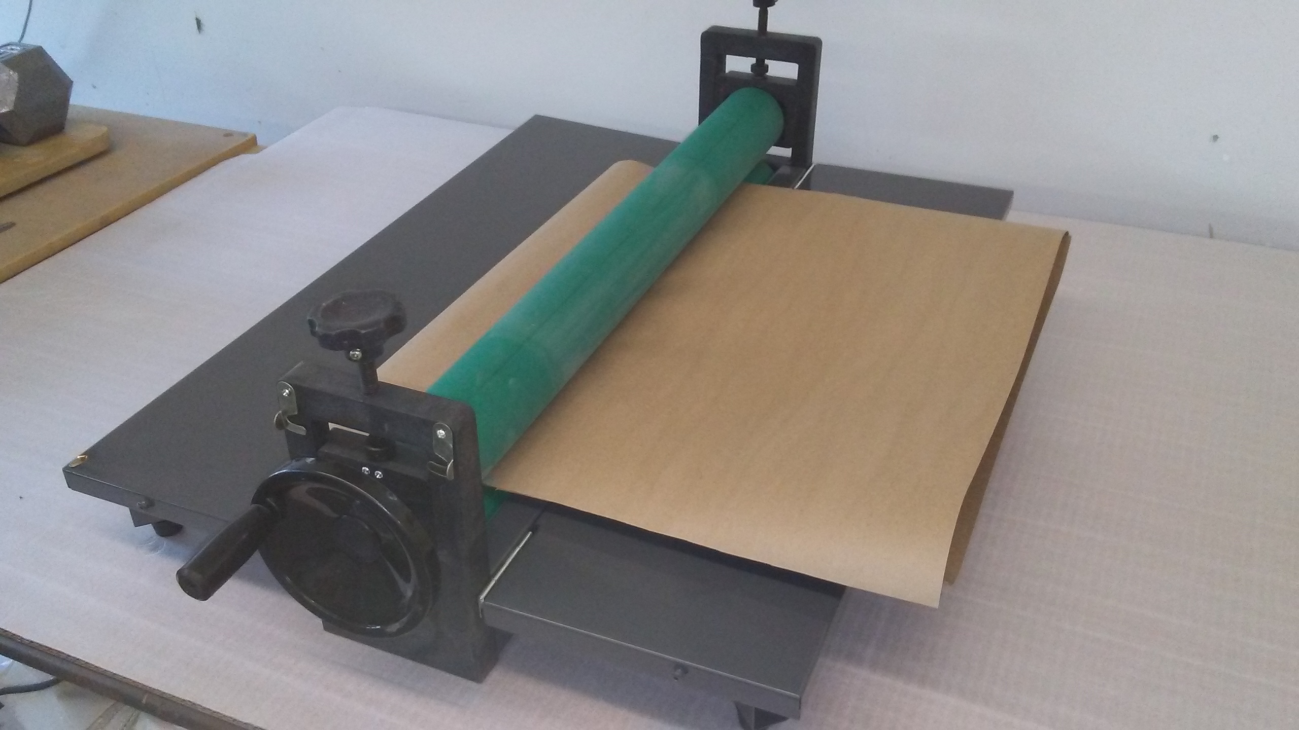
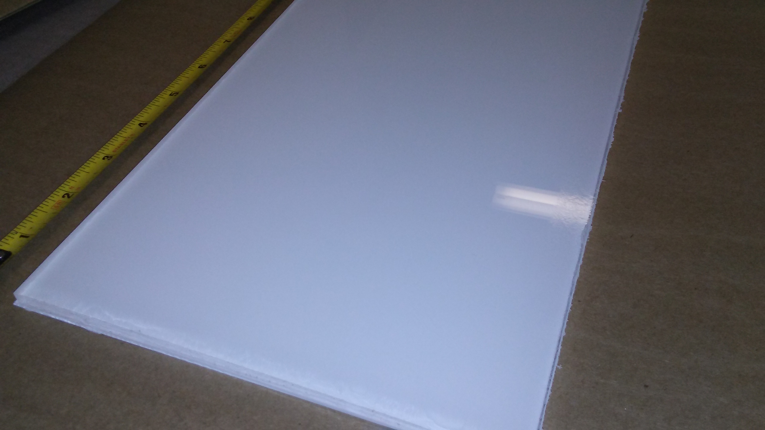
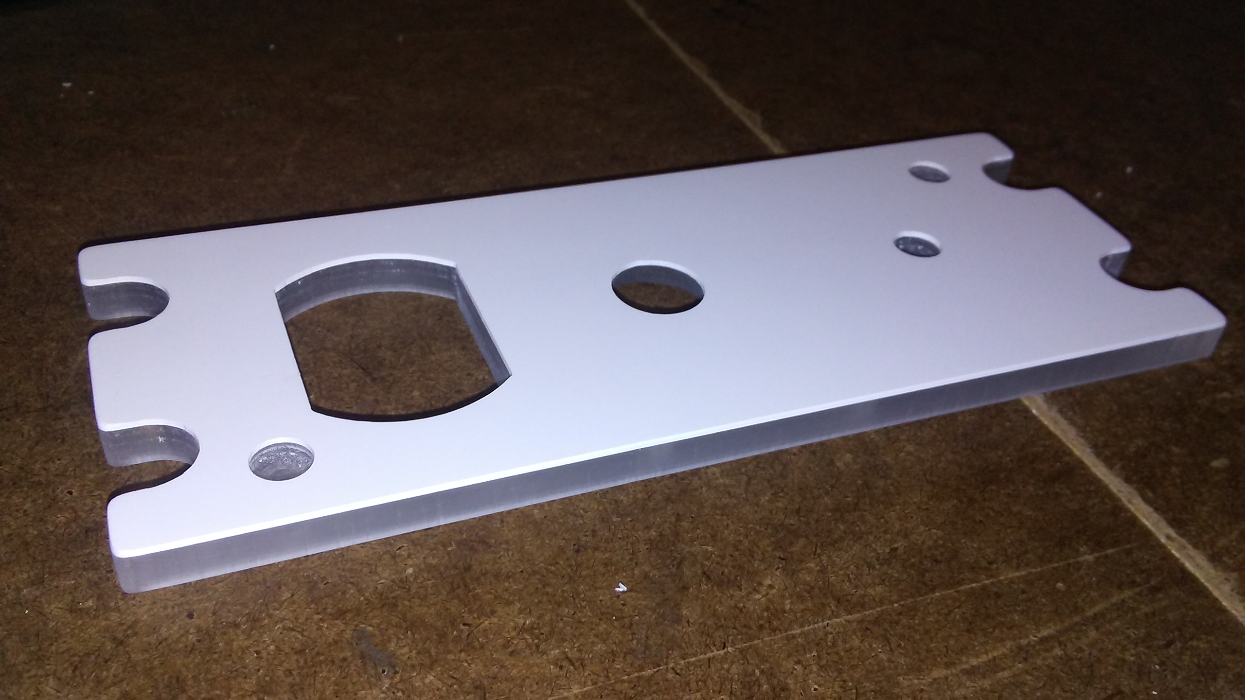
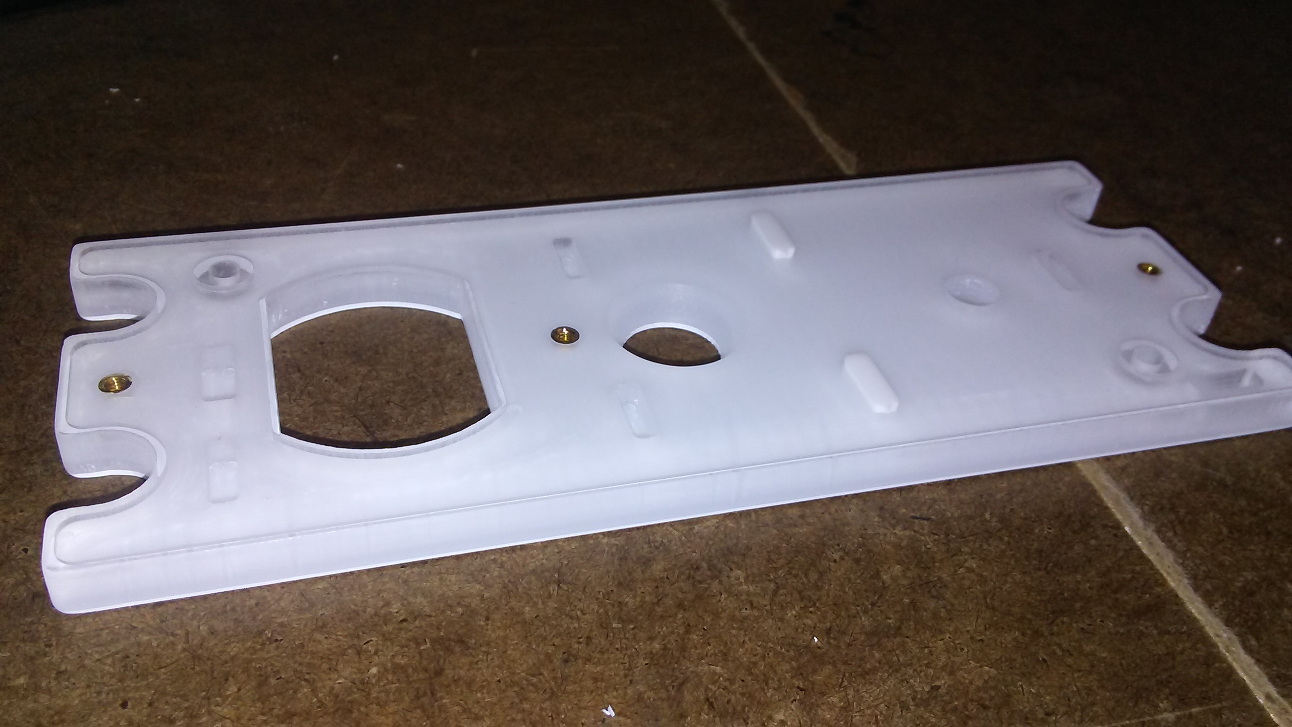
![]()

![]()
![]()
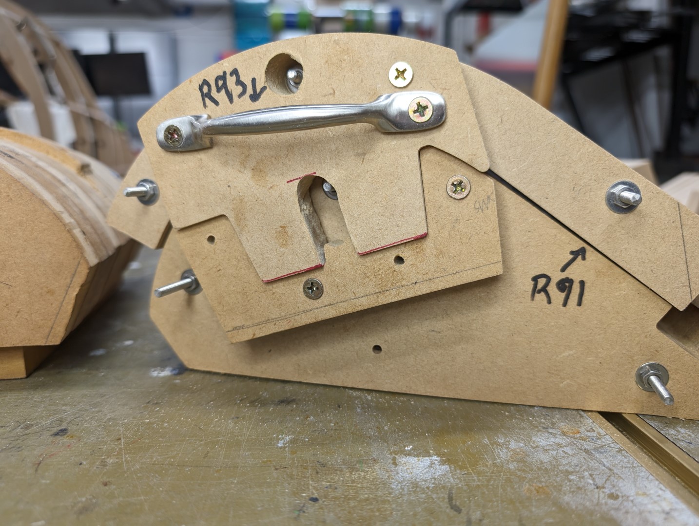
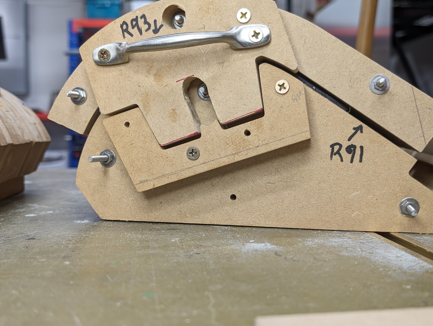
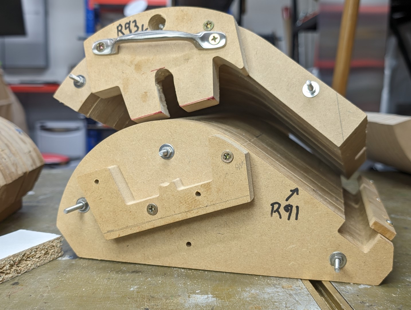
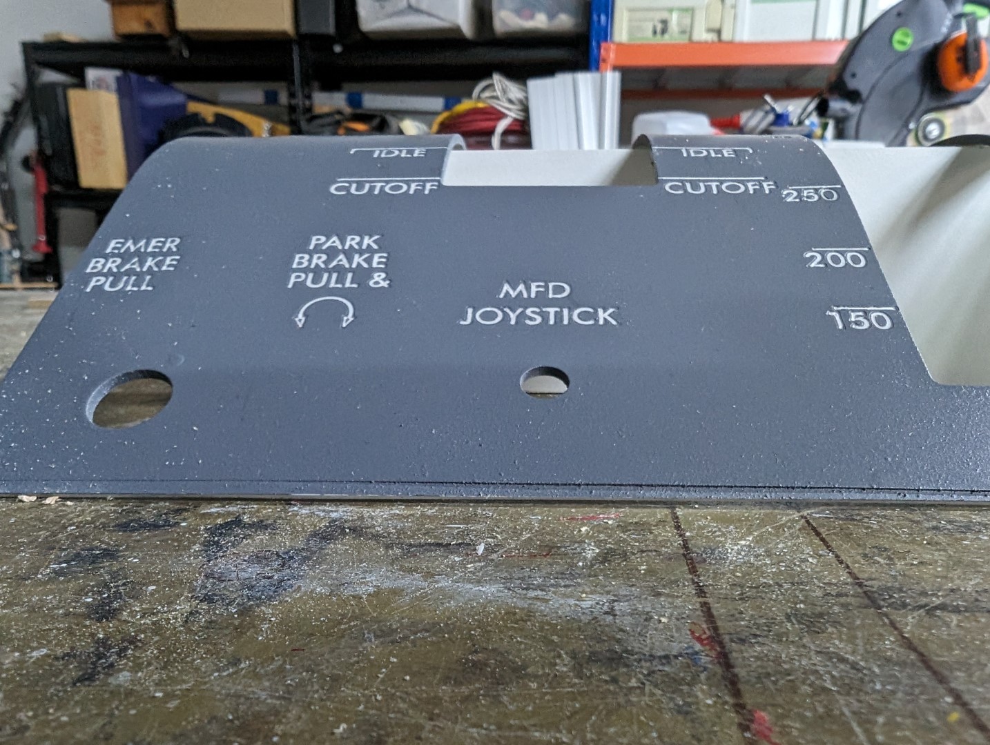
![]()

![]()
2017-10-10