


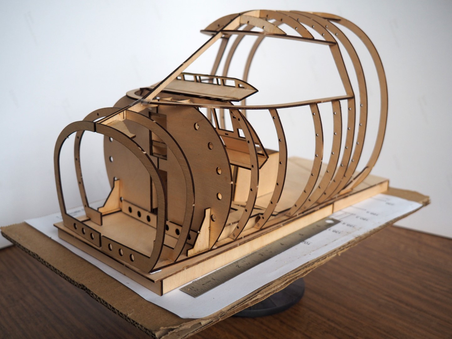
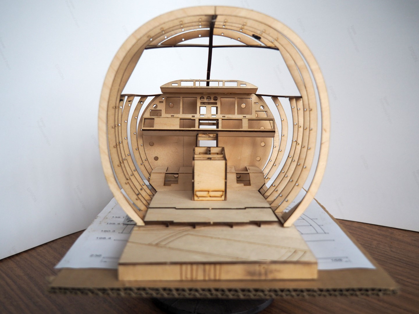
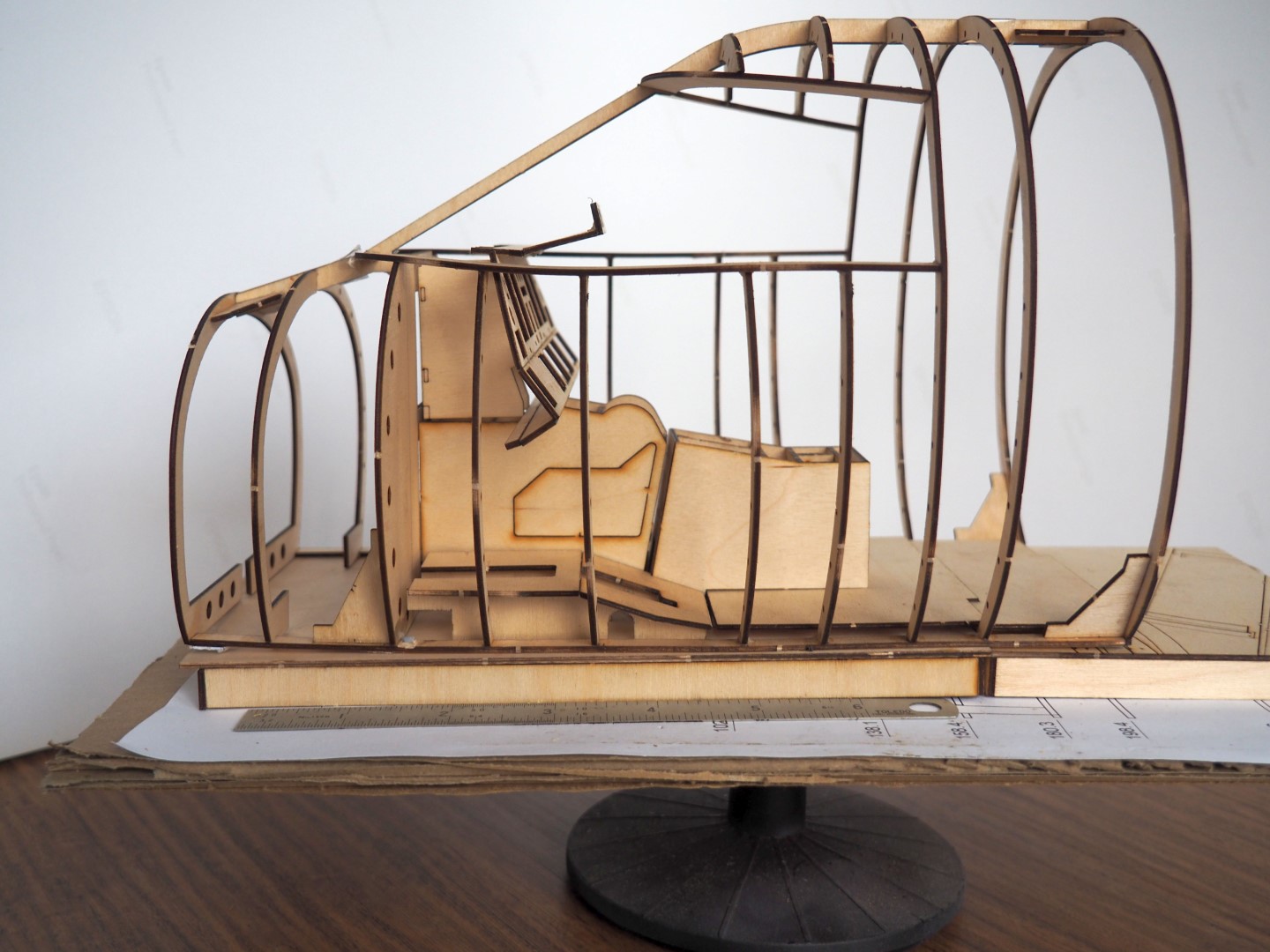
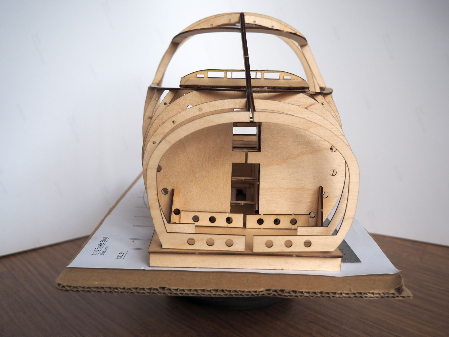
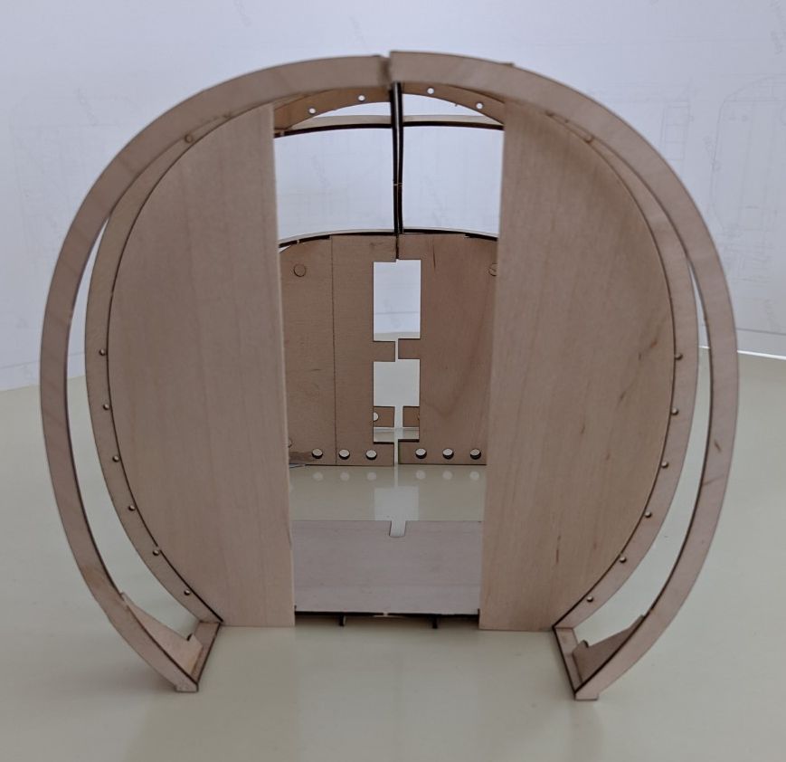
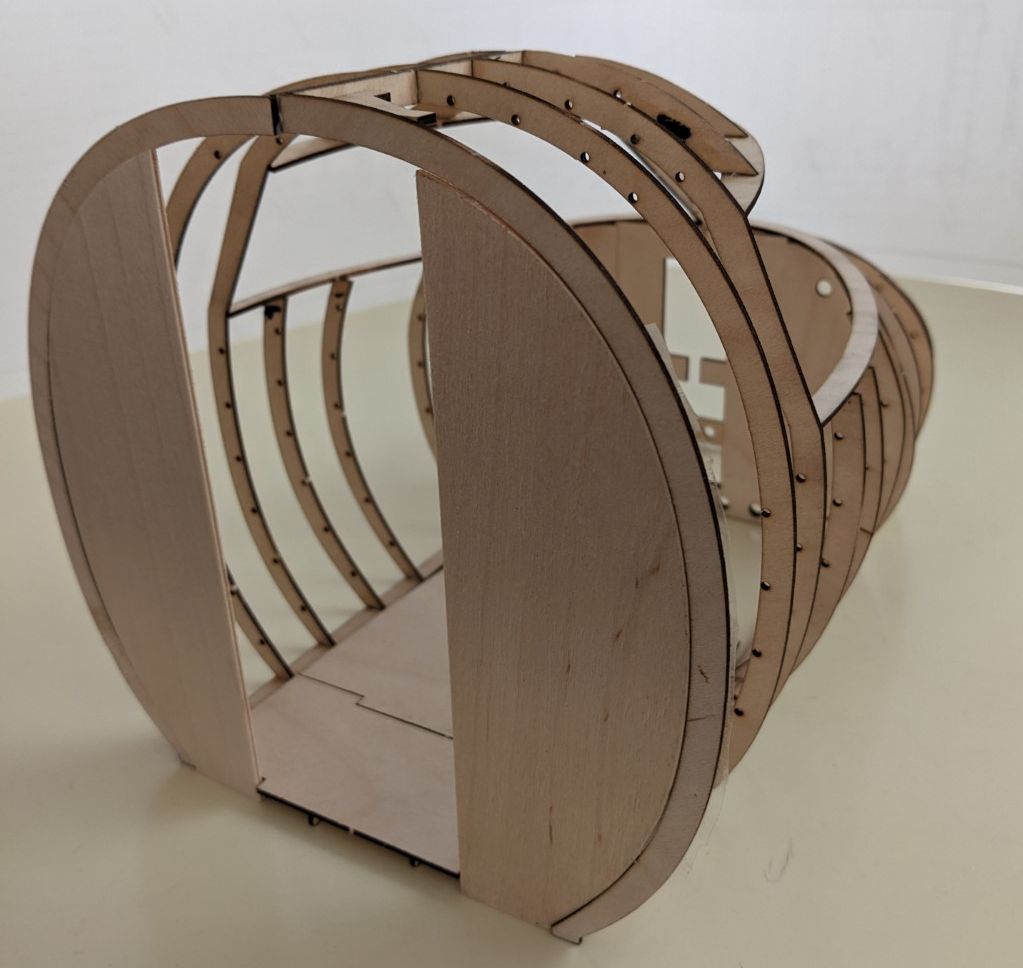
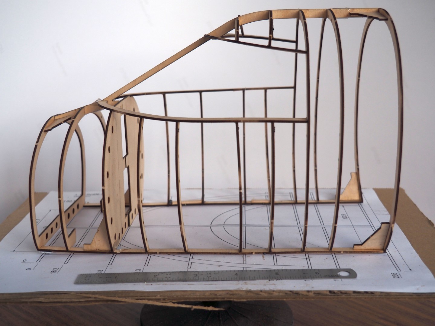
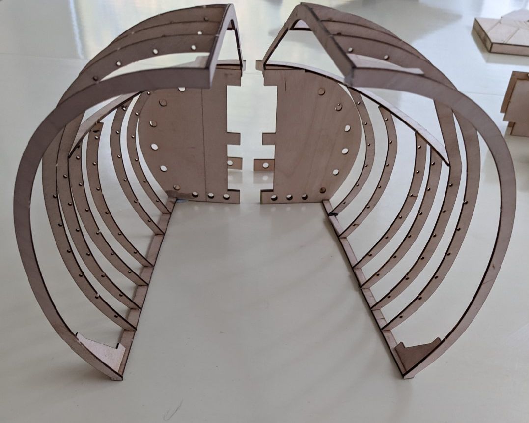
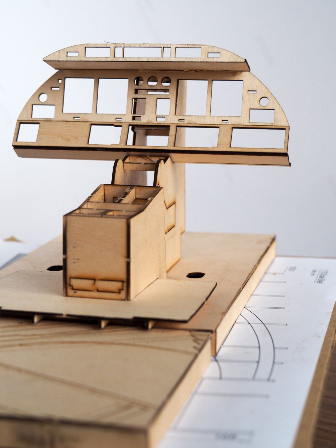
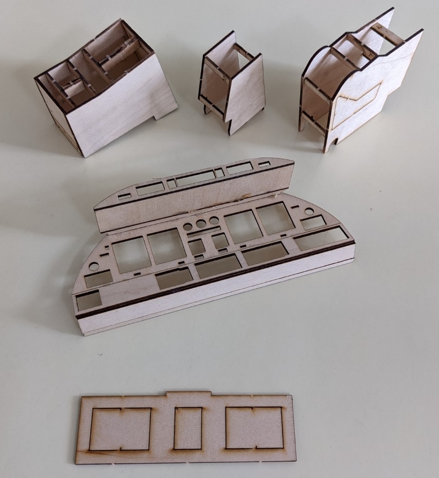
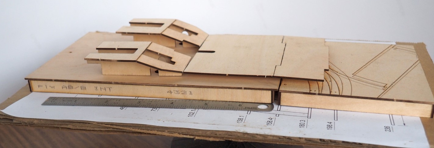
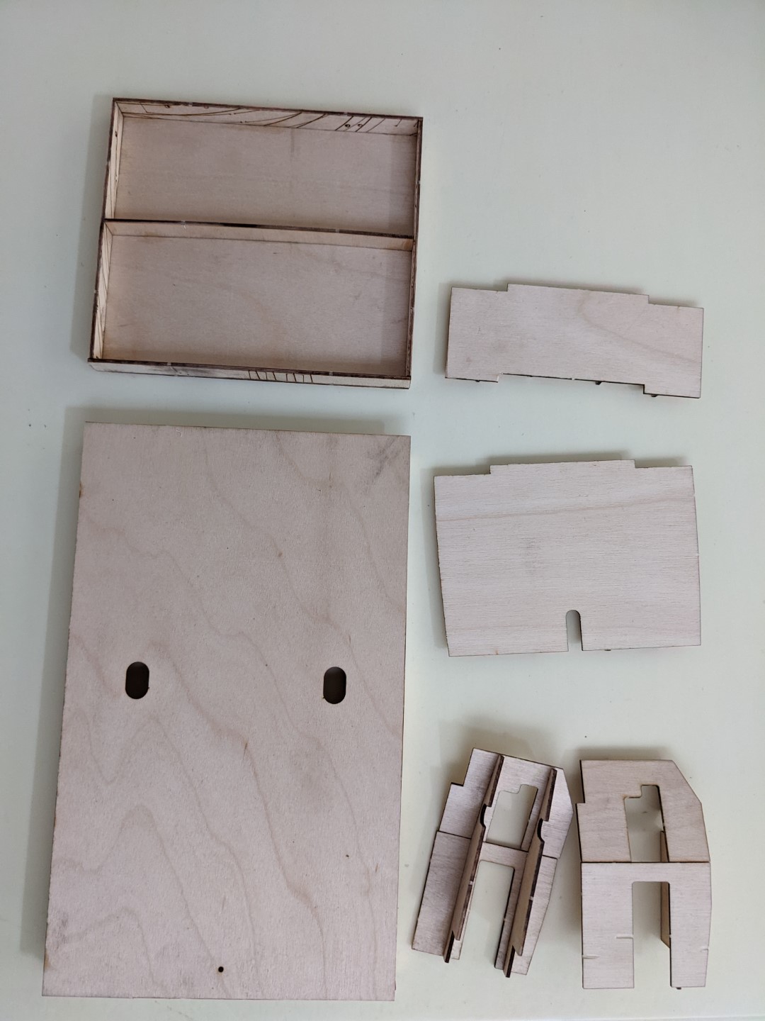
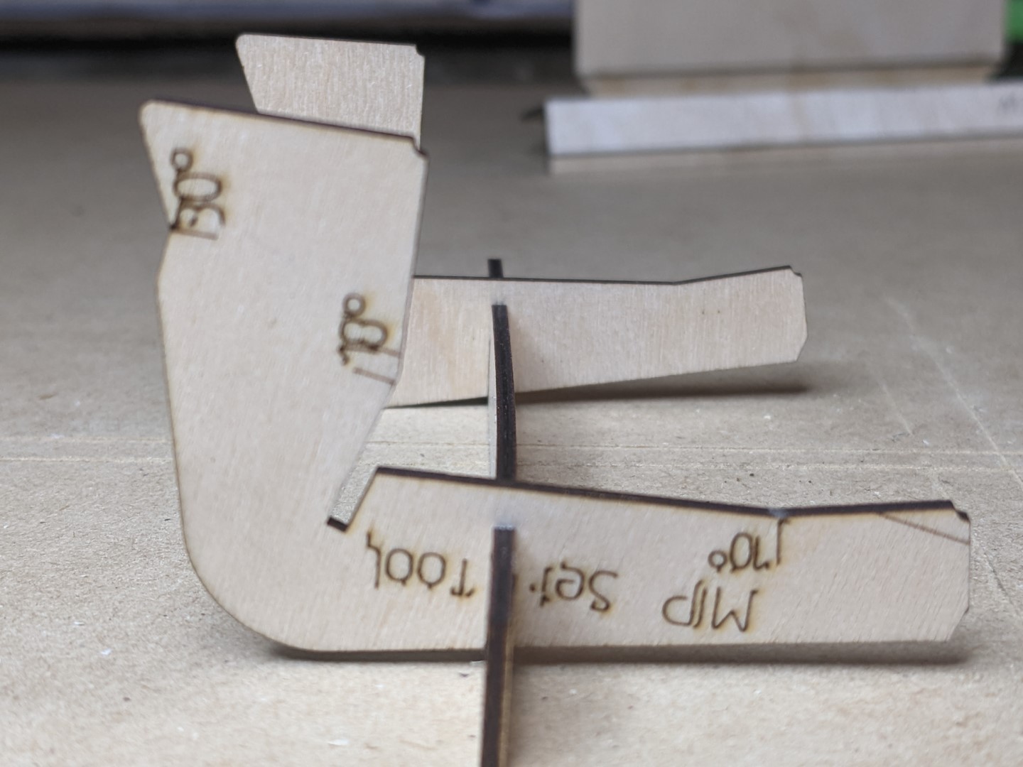
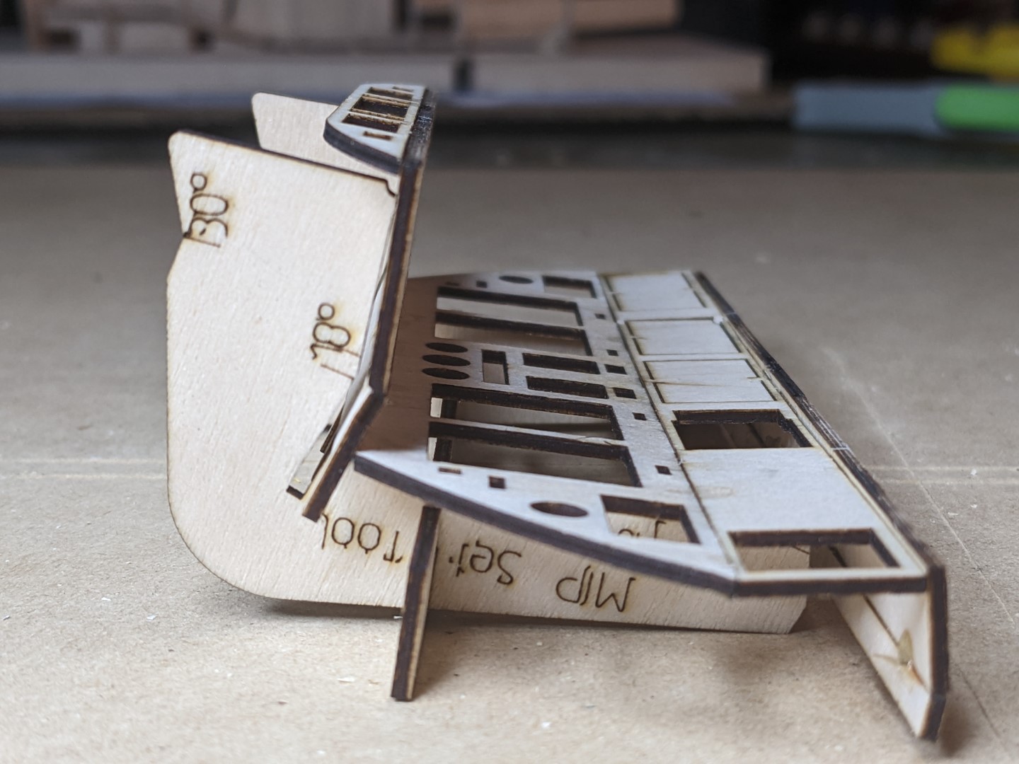
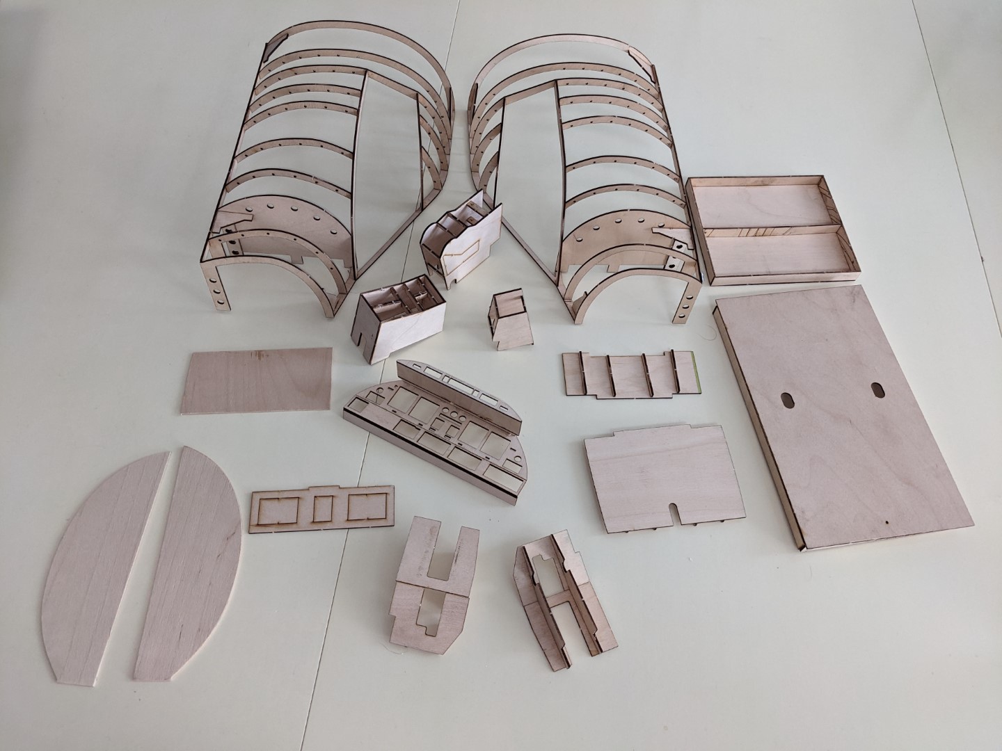
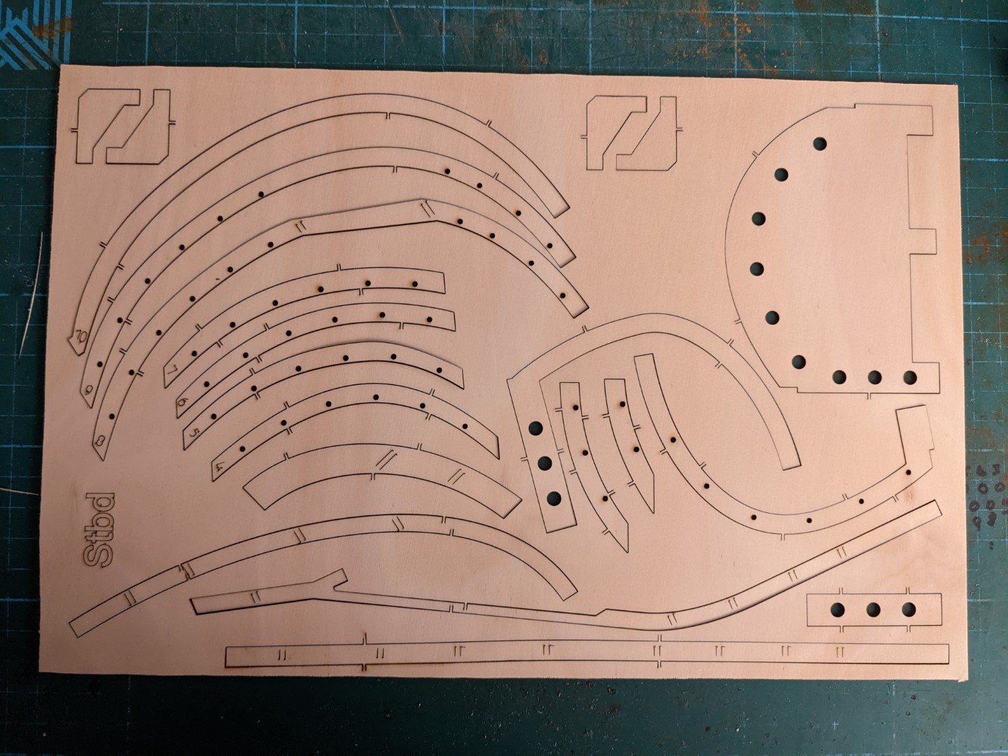
Hi Folks, Have you ever had friends say to you “nice cockpit, how did you build it?” Or “your gonna build a cockpit? How?” Perhaps you just want to try building something first to give you an idea of the process, Maybe you want a piece of aviation art. Well have I got something for you…. As part of proving the design of the digitised Learjet 45 cockpit shell (seen here) I created a 10% sized model directly from my full drawings size, with a few changes to deal with scaling and construction issues. Also to ensure I was good with clearances and sizes, and compatibility, I also digitised and shrunk the platform, raised deck, cockpit furniture, and MIP with glare shield panel – all to Ron's new version 2 standards. I laser cut this model's parts out of 1.5mm laserply, glued it together, and am very pleased with the result (photos below without rear walls and avionics bay deck). Having put in the effort to produce the proof-of-concept model, I did some more tinkering, and have created a kit for anyone who’d like one, for the price of US$120 + shipping. Some more details. Firstly, this is a kit. I will provide you with the parts laser cut into plywood sheets for you to pop-out, clean up and assemble using your tools and glue of choice. More on tools required at the end of this post. The kit can build either Ron's original (“Classic”) shell with the cockpit wall at F9, or the Long Shell (LS) version with a slightly longer shell and an F10 (see here for an explanation). It comes as an LS and the only adjustment needed to shorten it to a Classic is 4 cuts at pre-marked positions. All photos in this post are of the LS version. The cockpit rear wall fits inside F9 or F10. Where, or whether, you install it is up to you, Fitted to F9: Fitted to F10: There are three distinct modules of this model: 2. Cockpit furniture (MIP and consoles): Like the full-size this is built as four separate components: Centre Console, TQ Stand, MIP/Screen Tower, and MIP including glare shield panel. Plus the display screen backer. Platform with raised floor system: once again, it is built as per full size. Four components: left and right footwell floors, seat floor, and platform. Plus the extra platform and floor for the LS. I have also created a MIP assembly jig so that the angles between the faces of the MIP are correct and consistent. The internal angles provide a resting spot for mating parts to sit and be glued. All the completed components: The finished model can be fixed together into one complete component or left as multiple components. You can leave it as raw wood or paint it in clear or a colour with the appropriate prep work. I have tried to make this as easy to assemble as I could whilst maintaining the structure of the full size version, but I do not recommend this build for a novice as all the joins are butt or face joins – no tab and slot, no locating pins. Most of the joins have locating marks on the face of one piece. Here is a photo of the starboard frame laser cut sheet where you can see multiple pairs of lines on several pieces (on, from the bottom up, the base-rail, spine, lower and upper windshield frame, and on F8 towards top left). Each pair of lines indicate where a frame part is attached. These marks are designed to face the mating part and should be hidden on the finished model. The tools that are needed are: a sharp knife to cut the tabs on the parts, sandpaper, glue, clamps or a steady hand to hold parts for gluing. I have used both CA glue and wood glue and both worked well, with CA glue being faster. For clamping I used 1-2-3 blocks with spring clamps and 90° model making clamps which I already had. You don’t need to buy special tools, I also use short pieces of metal extrusion as clamping blocks and clothes peg as clamps. If you use soft metal (brass or aluminum) extrusion you can shape it to fit most situations. Likewise if you have wooden cloths pegs you can shape the tip however you want. I have created a variety of these over the years and make them as needed. I will provide an assembly guide and templates. If you’d like one let me know either here or by email. Price: US$120.00 plus shipping. Hi Folks, Have you ever had friends say to you “nice cockpit, how did you build it?” Or “your gonna build a cockpit? How?” Perhaps you just want to try building something first to give you an idea of the process, Maybe you want a piece of aviation art. Well have I got something for you…. As part of proving the design of the digitised Learjet 45 cockpit shell (seen here) I created a 10% sized model directly from my full drawings size, with a few changes to deal with scaling and construction issues. Also to ensure I was good with clearances and sizes, and compatibility, I also digitised and shrunk the platform, raised deck, cockpit furniture, and MIP with glare shield panel – all to Ron's new version 2 standards. I laser cut this model's parts out of 1.5mm laserply, glued it together, and am very pleased with the result (photos below without rear walls and avionics bay deck). Having put in the effort to produce the proof-of-concept model, I did some more tinkering, and have created a kit for anyone who’d like one, for the price of US$120 + shipping. Some more details. Firstly, this is a kit. I will provide you with the parts laser cut into plywood sheets for you to pop-out, clean up and assemble using your tools and glue of choice. More on tools required at the end of this post. The kit can build either Ron's original (“Classic”) shell with the cockpit wall at F9, or the Long Shell (LS) version with a slightly longer shell and an F10 (see here for an explanation). It comes as an LS and the only adjustment needed to shorten it to a Classic is 4 cuts at pre-marked positions. All photos in this post are of the LS version. The cockpit rear wall fits inside F9 or F10. Where, or whether, you install it is up to you, Fitted to F9: Fitted to F10: There are three distinct modules of this model: 2. Cockpit furniture (MIP and consoles): Like the full-size this is built as four separate components: Centre Console, TQ Stand, MIP/Screen Tower, and MIP including glare shield panel. Plus the display screen backer. Platform with raised floor system: once again, it is built as per full size. Four components: left and right footwell floors, seat floor, and platform. Plus the extra platform and floor for the LS. I have also created a MIP assembly jig so that the angles between the faces of the MIP are correct and consistent. The internal angles provide a resting spot for mating parts to sit and be glued. All the completed components: The finished model can be fixed together into one complete component or left as multiple components. You can leave it as raw wood or paint it in clear or a colour with the appropriate prep work. I have tried to make this as easy to assemble as I could whilst maintaining the structure of the full size version, but I do not recommend this build for a novice as all the joins are butt or face joins – no tab and slot, no locating pins. Most of the joins have locating marks on the face of one piece. Here is a photo of the starboard frame laser cut sheet where you can see multiple pairs of lines on several pieces (on, from the bottom up, the base-rail, spine, lower and upper windshield frame, and on F8 towards top left). Each pair of lines indicate where a frame part is attached. These marks are designed to face the mating part and should be hidden on the finished model. The tools that are needed are: a sharp knife to cut the tabs on the parts, sandpaper, glue, clamps or a steady hand to hold parts for gluing. I have used both CA glue and wood glue and both worked well, with CA glue being faster. For clamping I used 1-2-3 blocks with spring clamps and 90° model making clamps which I already had. You don’t need to buy special tools, I also use short pieces of metal extrusion as clamping blocks and clothes peg as clamps. If you use soft metal (brass or aluminum) extrusion you can shape it to fit most situations. Likewise if you have wooden cloths pegs you can shape the tip however you want. I have created a variety of these over the years and make them as needed. I will provide an assembly guide and templates. If you’d like one let me know either here or by email. Price: US$120.00 plus shipping. Hey Will, This is a very nice scale model of the shell! Thank you for taking the time to develop this model kit and digital shell so that anyone can have a shell kit cut anywhere in the world without having to worry about the cost of shipping a shell kit from the USA. I like the different options, "Classic Shell", "Long Shell", etc.... These are valid options for guys to consider. Most of us with a shell have the "Classic shell" but Mark S. has made his shell without the rear wall at F9 to make it open and easier to get in and out of the shell. I believe his seat rail extend out of the shell rearward making it as easy as sitting down in a seat and rolling into the shell. I have always had plans to make an extended shell with cabin door but have not yet got around to doing it. As you pointed out, it is as easy as copying F9 and extending the shell to the rear as far as you want. It is more difficult to get in and out of the cockpit but after all, the real Lear45 is no easier getting in and out of. I may change my mind about this in the future. Again, great job on the digital shell and this scale model Will! This is something that needed to be included to our Lear45 project lineup! Added to HANGAR PRODUCTS under "STRUCTURAL" tabs. Hey Will, This is a very nice scale model of the shell! Thank you for taking the time to develop this model kit and digital shell so that anyone can have a shell kit cut anywhere in the world without having to worry about the cost of shipping a shell kit from the USA. I like the different options, "Classic Shell", "Long Shell", etc.... These are valid options for guys to consider. Most of us with a shell have the "Classic shell" but Mark S. has made his shell without the rear wall at F9 to make it open and easier to get in and out of the shell. I believe his seat rail extend out of the shell rearward making it as easy as sitting down in a seat and rolling into the shell. I have always had plans to make an extended shell with cabin door but have not yet got around to doing it. As you pointed out, it is as easy as copying F9 and extending the shell to the rear as far as you want. It is more difficult to get in and out of the cockpit but after all, the real Lear45 is no easier getting in and out of. I may change my mind about this in the future. Again, great job on the digital shell and this scale model Will! This is something that needed to be included to our Lear45 project lineup! Added to HANGAR PRODUCTS under "STRUCTURAL" tabs. Fantastic work Will. I can see many hours developing this package. A great addition to Hangar Products! Fantastic work Will. I can see many hours developing this package. A great addition to Hangar Products!Scale Model Kit of Project45 Shell frame
![]()
![]()
![]()
![]()
2017-10-10