


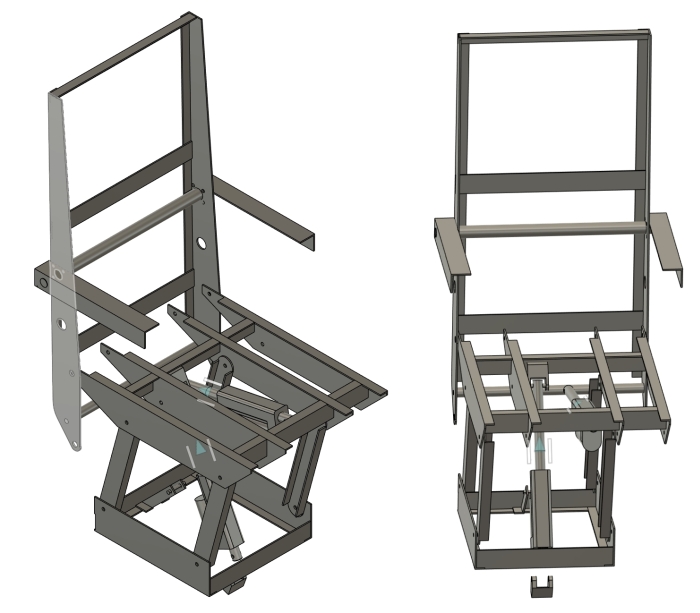
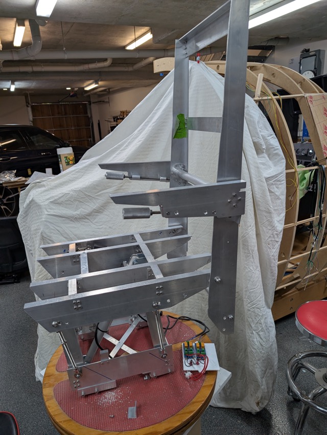
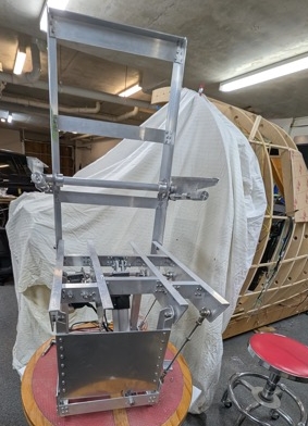
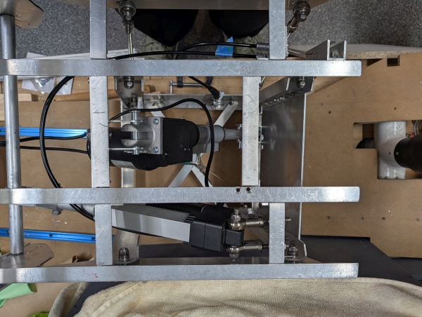
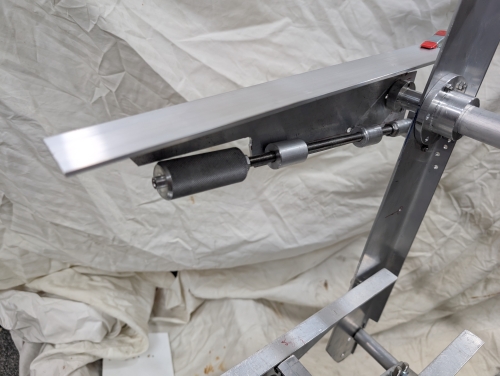
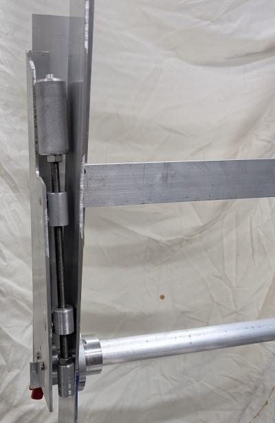
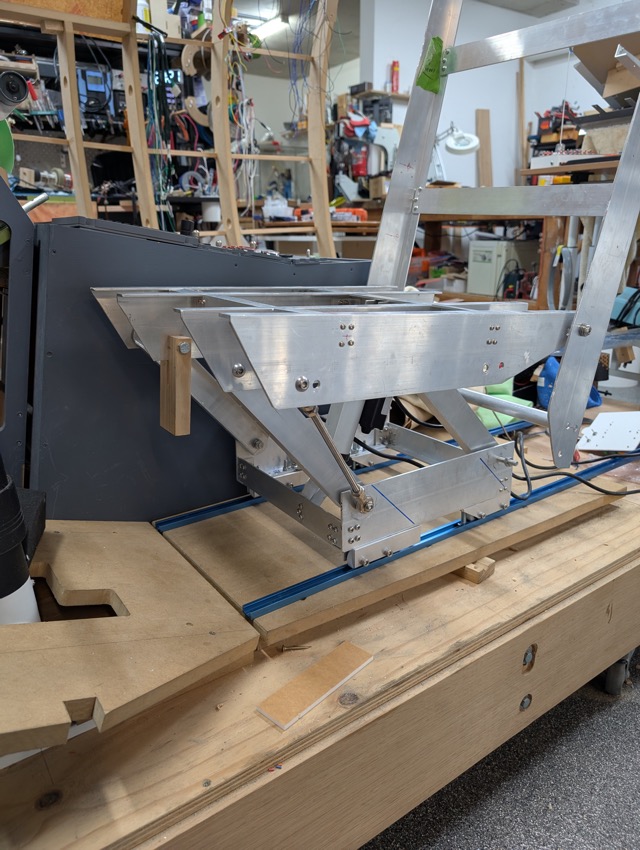
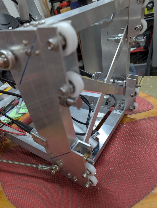
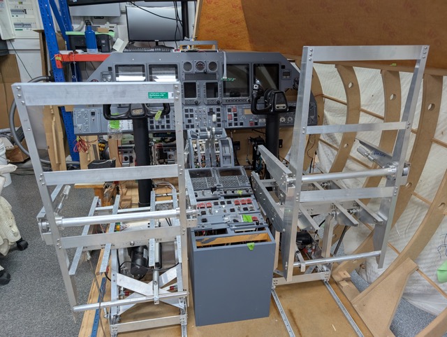
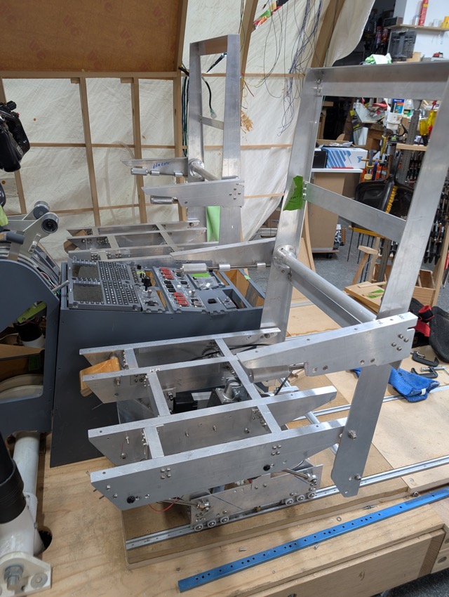
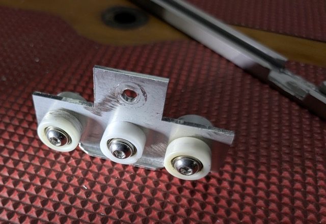
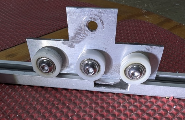
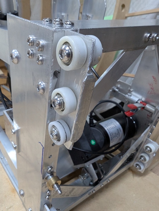
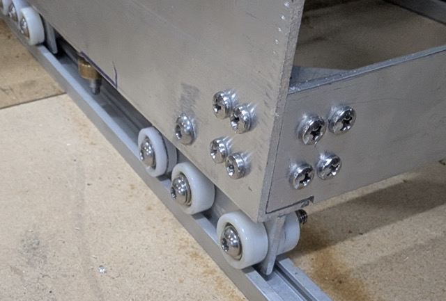
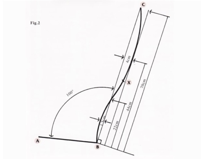
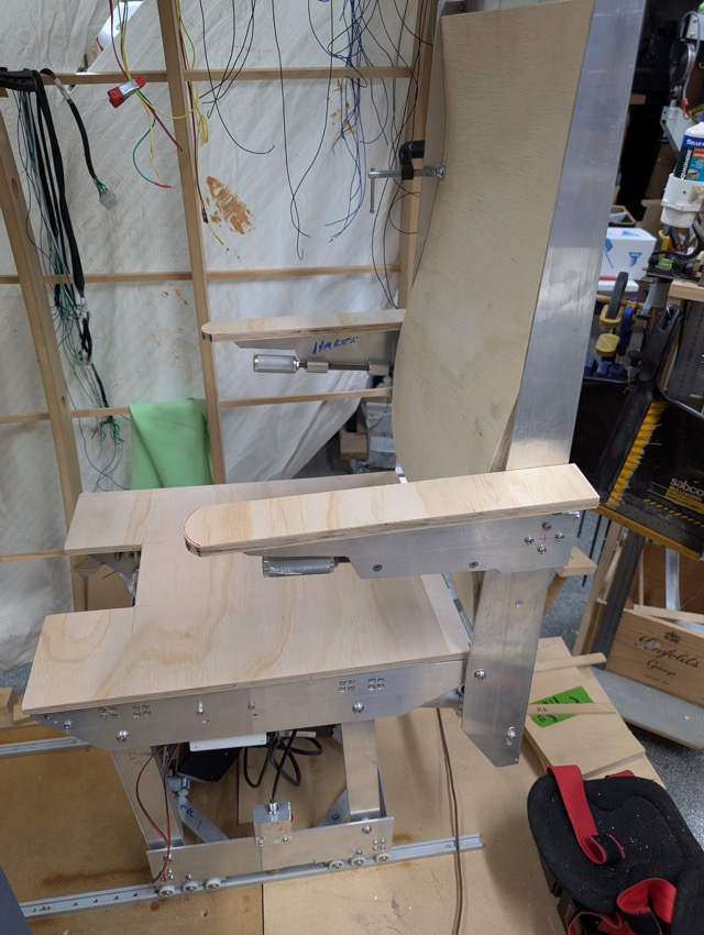
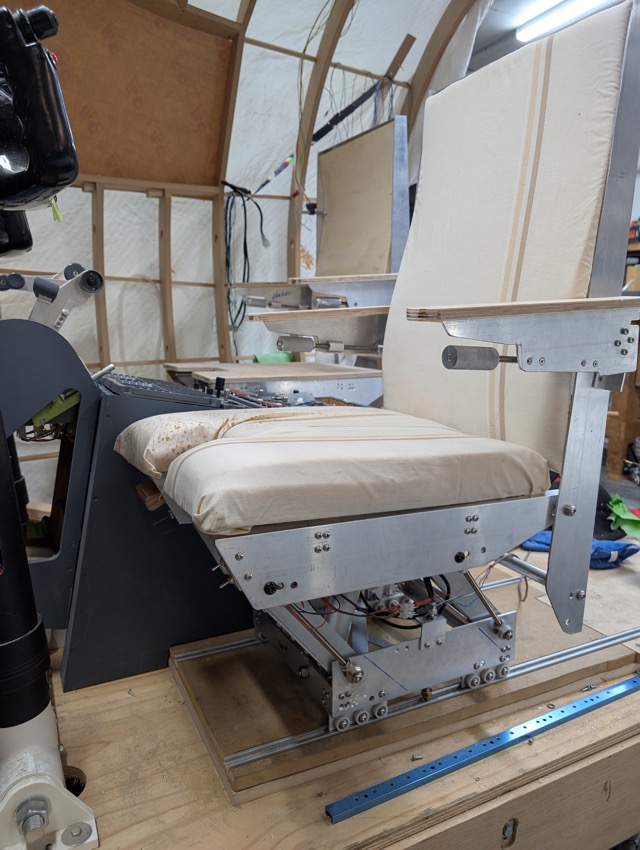
Hi Folks, I have been watching and waiting for a pair of used pilot seats that would fit our sims for a while now, with no success. The idea of spending thousands of dollars + freight for seats that may not fit didn’t thrill me. I decided to have a go at building them myself. Reviewing Ron's earlier posts, seeing his progress with his version, asking a few questions and I realised I didn’t want to build in plastic. I was much happier to build in aluminium. Ron had already created a 2D CAD file for the main components of a seat, so all I had to do was come up with the 3rd dimensions and all mechanisms. From Ron's 2D drawings and some photos (also from Ron), I drew up this 3D version which is a little bit more utilitarian in shape of components. I didn’t want to do any fancy scroll cutting of aluminium, so its straight lines and right angle corners for most parts. This is purely a design guide with no detail, I would work that out as I built. Which led to this It has the offset base and can be assembled with the overhang to left or right, to suit left or right cockpit seats. I chose to power the seat raise/lower, as well as the seat back angle. This was easier (to me) than fitting a manual rotating shaft and handle. I used two linear actuators - the seat raise/lower is a 3000N (300kg) 10mm/s 100mm actuator, and the seat back is a 3000N (300Kg) 5mm/s 100mm unit. Both are activated by switches under the front of the seat. Each actuators extend/retract is controlled by an SPST toggle (MOM-OFF-MOM), through one of my Polarity Changers which handles switching the reversal of the current, to the actuator. Vertical movement is currently about 55mm. I will attempt to increase this to about 65mm with a bit of actuator position tweaking. The armrests pivot on a pin that is fixed to the armrest and slides in a tube across the backrest, held in position by a custom flange at each end. They can be rotated to vertical and stowed. They are adjustable for height by rotating around the pin. The adjuster is an M8 threaded rod with a free floating knob on one end and push block on the other, and two fixed guide blocks. One guide block is threaded M8., the other is drilled clear 8mm. the push block presses against a tab on the seat back below the armrest pin. Pilot spins the knob which moves the push block in or out which changes the resting angle of the armrest. The seat rolls on nylon tread ball bearings which fit into a woodworkers bench type ‘T’ track. I use one of the "T" track accessories to prevent lifting out of the track. I made custom spring loaded pin and guide bushes for fore/aft movement lock. These pins fit into 5mm holes I drilled in the "T" track. These holes are drilled at 1” spacing for the first 18”. The pins are retracted for seat fore/aft adjustment using pull cables to a lever just under the seat. That’s where I’m at at the moment. Got a couple minor issues to resolve (ie I had to move two of the leg pivot 8mm bolt holes 3mm to the front, that was interesting!) Soon I will cut some plywood for seat base, armrests, and backrest, to be upholstered. For the all important lumbar support (on those long flights) I will bend the seat back in an ergonomic design, fixed lumbar support, until I can "imagineer" an adjustable one, if needed. Some specs of this build are: I am very happy with the seat. It feels quite solid, runs cleanly and smoothly in the "T" track, the motors work nicely (so far), it does have a resemblance to the photos of a real Tal J2, and best of all I have less than $800 invested in it, including freight! Yeeah, okay, it has taken me a month of time, but that was fun!! The next one will cost less and take far less time – I know what I’m doing now. I will be making the co-pilot seat soon. All the same pieces just connected to the other two main fore/aft beams… overhang right… Easy!!! If anyone wants I will make a CAD file available, but it will take me a little while to finish it. It turns out that the seats are not that difficult to replicate! This is just a brief overview of my build. I am happy to provide more details if desired. Enjoy... Hi Folks, I have been watching and waiting for a pair of used pilot seats that would fit our sims for a while now, with no success. The idea of spending thousands of dollars + freight for seats that may not fit didn’t thrill me. I decided to have a go at building them myself. Reviewing Ron's earlier posts, seeing his progress with his version, asking a few questions and I realised I didn’t want to build in plastic. I was much happier to build in aluminium. Ron had already created a 2D CAD file for the main components of a seat, so all I had to do was come up with the 3rd dimensions and all mechanisms. From Ron's 2D drawings and some photos (also from Ron), I drew up this 3D version which is a little bit more utilitarian in shape of components. I didn’t want to do any fancy scroll cutting of aluminium, so its straight lines and right angle corners for most parts. This is purely a design guide with no detail, I would work that out as I built. Which led to this It has the offset base and can be assembled with the overhang to left or right, to suit left or right cockpit seats. I chose to power the seat raise/lower, as well as the seat back angle. This was easier (to me) than fitting a manual rotating shaft and handle. I used two linear actuators - the seat raise/lower is a 3000N (300kg) 10mm/s 100mm actuator, and the seat back is a 3000N (300Kg) 5mm/s 100mm unit. Both are activated by switches under the front of the seat. Each actuators extend/retract is controlled by an SPST toggle (MOM-OFF-MOM), through one of my Polarity Changers which handles switching the reversal of the current, to the actuator. Vertical movement is currently about 55mm. I will attempt to increase this to about 65mm with a bit of actuator position tweaking. The armrests pivot on a pin that is fixed to the armrest and slides in a tube across the backrest, held in position by a custom flange at each end. They can be rotated to vertical and stowed. They are adjustable for height by rotating around the pin. The adjuster is an M8 threaded rod with a free floating knob on one end and push block on the other, and two fixed guide blocks. One guide block is threaded M8., the other is drilled clear 8mm. the push block presses against a tab on the seat back below the armrest pin. Pilot spins the knob which moves the push block in or out which changes the resting angle of the armrest. The seat rolls on nylon tread ball bearings which fit into a woodworkers bench type ‘T’ track. I use one of the "T" track accessories to prevent lifting out of the track. I made custom spring loaded pin and guide bushes for fore/aft movement lock. These pins fit into 5mm holes I drilled in the "T" track. These holes are drilled at 1” spacing for the first 18”. The pins are retracted for seat fore/aft adjustment using pull cables to a lever just under the seat. That’s where I’m at at the moment. Got a couple minor issues to resolve (ie I had to move two of the leg pivot 8mm bolt holes 3mm to the front, that was interesting!) Soon I will cut some plywood for seat base, armrests, and backrest, to be upholstered. For the all important lumbar support (on those long flights) I will bend the seat back in an ergonomic design, fixed lumbar support, until I can "imagineer" an adjustable one, if needed. Some specs of this build are: I am very happy with the seat. It feels quite solid, runs cleanly and smoothly in the "T" track, the motors work nicely (so far), it does have a resemblance to the photos of a real Tal J2, and best of all I have less than $800 invested in it, including freight! Yeeah, okay, it has taken me a month of time, but that was fun!! The next one will cost less and take far less time – I know what I’m doing now. I will be making the co-pilot seat soon. All the same pieces just connected to the other two main fore/aft beams… overhang right… Easy!!! If anyone wants I will make a CAD file available, but it will take me a little while to finish it. It turns out that the seats are not that difficult to replicate! This is just a brief overview of my build. I am happy to provide more details if desired. Enjoy... Looks very complex yet clean designed. Impressed with your engineering skills! Looks very complex yet clean designed. Impressed with your engineering skills! Hey Will, Thank you for posting up your seat prototype for all to see! Your work is very impressive and absolutely needed to be shared with the others to see. And as you said, the seats are not as complicated as you would first think. I am working on that third view in my Master Seat DXF as I type, so here in the near future, anyone else that wants to build their own seats they will have a more complete drawing set to work with and go along with the 3D drawing you will be providing. I really do like the idea of motorized lifts for the seats. This is not something that is included in the real crew seats but makes sense for us. I was struggling with how I was going to raise and lower the seat without the seat being a danger to the person sitting on it. I worried about pinched fingers more than anything. A motorized lift solves that problem. And you will be able to adjust the seat height to anything level at the flip of a switch. I can see I am going to end up borrowing some of your ideas to finish my prototype crew seats once I get started on them again. I keep saying this, but it's hard for me to work on seats or TQ covers, etc... until I have some of the bigger more pressing things resolved, not just for myself but for all of us. I am looking forward to your next update! Hey Will, Thank you for posting up your seat prototype for all to see! Your work is very impressive and absolutely needed to be shared with the others to see. And as you said, the seats are not as complicated as you would first think. I am working on that third view in my Master Seat DXF as I type, so here in the near future, anyone else that wants to build their own seats they will have a more complete drawing set to work with and go along with the 3D drawing you will be providing. I really do like the idea of motorized lifts for the seats. This is not something that is included in the real crew seats but makes sense for us. I was struggling with how I was going to raise and lower the seat without the seat being a danger to the person sitting on it. I worried about pinched fingers more than anything. A motorized lift solves that problem. And you will be able to adjust the seat height to anything level at the flip of a switch. I can see I am going to end up borrowing some of your ideas to finish my prototype crew seats once I get started on them again. I keep saying this, but it's hard for me to work on seats or TQ covers, etc... until I have some of the bigger more pressing things resolved, not just for myself but for all of us. I am looking forward to your next update! I have finally finished the metal work for seat #2 – the Co Pilots seat. I built the same frame only mounted the seat to overhand the right. Everything re-positioned itself easily and accurately. This one went much smoother (of course!) with a few changes (of course!). Both seats installed, captains full down, co-pilots full up.` The biggest change was to the roller wheel carriages in each corner. In version one I had two 30x9x6 nylon covered rollers at each of the four corners, rolling in the slot of the track with separate short ‘T’ piece hold-down which slid in the track (see photo 8 of post #1 above). I found the rollers would clunk or stop as they ran over the screws holding the tracks to the floor, and clunk over the multiple holes for the for/aft locking pins. This was not comfortable. I also found the ‘T’ piece hold-down would jam in the track. Although it was vertically adjustable to centre it in the track, the foot part was too short and would twist allowing the corners to jam in the track. To smooth the ride I moved the rollers to the top of the track (where there are no holes), and added a third wheel. To balance forces and prevent side load distorting the assembly I added a second row of three wheels to each carriage. That gave me 6 of 20x9x6 nylon coated bearings per corner. To stop the ‘T’ piece jamming I increased its length and incorporated it into the wheel carriage, now it’s a ‘T” blade. I effectively flipped the carriage, the wheels on top and the ‘T’ blade under. This did require precision as there is no adjustability to the blade heights or the wheels relative to the track. This is a 2mm thick blade running in a 3.5mm high slot – not a lot of room for errors Like the rest of the construction, the wheel carriage frame is 3mm thick 50x50 Tee aluminium, with the 50mm top being cut/machined down to 12mm wide to fit the T-track slot. This shortened top is also machined to a thickness of 2mm. The 50mm stem of the Tee is shaped to a central single tab which is used to bolt the assembly to the seat frame base. The 20mm diameter rollers are mounted so that there is a 3mm gap between the rollers and the top of the blade This carriage assembly can be shimmed from the frame to ensure alignment of the four carriages. The track width of the front pair must be the same as the back pair, and they need to be aligned front to back, to run in the T-Track smoothly. Here is a photo of the aperture in the seat base for the carriage tab, with bolt and a 6mm plastic shim: The carriage assembly mounted: I used 6-wheel carriages as this is smoother than 4-wheel, particularly over bumps, divots, holes, and joints. To ease getting in and out of the cockpit I am installing seat track the full length of my flat floor, from the ramp at the bottom of the control column to the rear edge of the my platform (300mm longer than standard), a distance of about 2.2m. This needs a 2-piece track so a 6 wheel works better than a 4 wheel. The seat track width was calculated, spacer blocks cut and used to install the tracks So far it seems to work well, nice and smooth and with a little silicone lubricant on the track it slides fore/aft cleanly from one end to the other. I have laminated the backrest timber support piece using 3 layers of 5mm bamboo (bendy) plywood. This was laminated on a jig I made to conform with this document from the web. ( Wood review: How to make a comfortable chair ). The finished piece is a 15mm very solid curved backrest that actually is comfortable. The seat base is a flat piece of 12mm marine plywood. Next will be upholstery. Whilst waiting for some proper foam and material, using some foam that I had to hand, and some old bed linen, I ‘upholstered’ one seat and backrest to see how it I will look… I think this may work! I have finally finished the metal work for seat #2 – the Co Pilots seat. I built the same frame only mounted the seat to overhand the right. Everything re-positioned itself easily and accurately. This one went much smoother (of course!) with a few changes (of course!). Both seats installed, captains full down, co-pilots full up.` The biggest change was to the roller wheel carriages in each corner. In version one I had two 30x9x6 nylon covered rollers at each of the four corners, rolling in the slot of the track with separate short ‘T’ piece hold-down which slid in the track (see photo 8 of post #1 above). I found the rollers would clunk or stop as they ran over the screws holding the tracks to the floor, and clunk over the multiple holes for the for/aft locking pins. This was not comfortable. I also found the ‘T’ piece hold-down would jam in the track. Although it was vertically adjustable to centre it in the track, the foot part was too short and would twist allowing the corners to jam in the track. To smooth the ride I moved the rollers to the top of the track (where there are no holes), and added a third wheel. To balance forces and prevent side load distorting the assembly I added a second row of three wheels to each carriage. That gave me 6 of 20x9x6 nylon coated bearings per corner. To stop the ‘T’ piece jamming I increased its length and incorporated it into the wheel carriage, now it’s a ‘T” blade. I effectively flipped the carriage, the wheels on top and the ‘T’ blade under. This did require precision as there is no adjustability to the blade heights or the wheels relative to the track. This is a 2mm thick blade running in a 3.5mm high slot – not a lot of room for errors Like the rest of the construction, the wheel carriage frame is 3mm thick 50x50 Tee aluminium, with the 50mm top being cut/machined down to 12mm wide to fit the T-track slot. This shortened top is also machined to a thickness of 2mm. The 50mm stem of the Tee is shaped to a central single tab which is used to bolt the assembly to the seat frame base. The 20mm diameter rollers are mounted so that there is a 3mm gap between the rollers and the top of the blade This carriage assembly can be shimmed from the frame to ensure alignment of the four carriages. The track width of the front pair must be the same as the back pair, and they need to be aligned front to back, to run in the T-Track smoothly. Here is a photo of the aperture in the seat base for the carriage tab, with bolt and a 6mm plastic shim: The carriage assembly mounted: I used 6-wheel carriages as this is smoother than 4-wheel, particularly over bumps, divots, holes, and joints. To ease getting in and out of the cockpit I am installing seat track the full length of my flat floor, from the ramp at the bottom of the control column to the rear edge of the my platform (300mm longer than standard), a distance of about 2.2m. This needs a 2-piece track so a 6 wheel works better than a 4 wheel. The seat track width was calculated, spacer blocks cut and used to install the tracks So far it seems to work well, nice and smooth and with a little silicone lubricant on the track it slides fore/aft cleanly from one end to the other. I have laminated the backrest timber support piece using 3 layers of 5mm bamboo (bendy) plywood. This was laminated on a jig I made to conform with this document from the web. ( Wood review: How to make a comfortable chair ). The finished piece is a 15mm very solid curved backrest that actually is comfortable. The seat base is a flat piece of 12mm marine plywood. Next will be upholstery. Whilst waiting for some proper foam and material, using some foam that I had to hand, and some old bed linen, I ‘upholstered’ one seat and backrest to see how it I will look… I think this may work! Hey Will, Your seats are looking amazing! Even though they are not finished they are looking like something you might expect to see in a cockpit of an aircraft! Great work and thanks for sharing this with us all. Now for the real fun part, the upholstery. I have thought about doing that part myself also but think I will just have someone who does this sort of work day in and day out do it. But I will cut the foam! Looking forward to the next round of photos! Hey Will, Your seats are looking amazing! Even though they are not finished they are looking like something you might expect to see in a cockpit of an aircraft! Great work and thanks for sharing this with us all. Now for the real fun part, the upholstery. I have thought about doing that part myself also but think I will just have someone who does this sort of work day in and day out do it. But I will cut the foam! Looking forward to the next round of photos! Wow.. my wooden chair looks likenothing compared to this! Wow.. my wooden chair looks likenothing compared to this! This is awesome! Back in 2024, I was able to pick up a pair of Lear55 seats from ebay which are great because they are real, but they came with a lot of headaches. Namely, finding a way to adapt the guide rollers to a DIY track. DonnyRay had already tackled this beast but his seats were a bit different than mine. In the end, I found a 'track' which was an aluminum T-extrusion used to hang doors from, and with some washers and new bolts was able to widen the roller assemblies to fit the tracks. However, another issue is that even though they are the real seats, they seem to be too wide to fit our sims. This is evident that when the seats are installed directly against the center pedestal, the yoke doesn't align with the cutout in the seat. Now I know that Ron has measured the yoke distance in the real aircraft and based his kit off of that and having verified my columns meet that measurement there is some misalignment. Additionally, you cannot get your hand in between the seat and the center pedestal to pull the track lever to move the seat forward and aft. Having a custom seat option is a great way to ensure everything fits comfortably! This is awesome! Back in 2024, I was able to pick up a pair of Lear55 seats from ebay which are great because they are real, but they came with a lot of headaches. Namely, finding a way to adapt the guide rollers to a DIY track. DonnyRay had already tackled this beast but his seats were a bit different than mine. In the end, I found a 'track' which was an aluminum T-extrusion used to hang doors from, and with some washers and new bolts was able to widen the roller assemblies to fit the tracks. However, another issue is that even though they are the real seats, they seem to be too wide to fit our sims. This is evident that when the seats are installed directly against the center pedestal, the yoke doesn't align with the cutout in the seat. Now I know that Ron has measured the yoke distance in the real aircraft and based his kit off of that and having verified my columns meet that measurement there is some misalignment. Additionally, you cannot get your hand in between the seat and the center pedestal to pull the track lever to move the seat forward and aft. Having a custom seat option is a great way to ensure everything fits comfortably!Replica Seats by Will_S
![]()
![]()
![]()
![]()

![]()
![]()
Very good job!
Very good job!![]()
Forum NavigationReplica Seats by Will_S
![]() #1 · March 17, 2026, 6:27 amRon Rollo and HunkaBurninLove have reacted to this post.Ron RolloHunkaBurninLove
#1 · March 17, 2026, 6:27 amRon Rollo and HunkaBurninLove have reacted to this post.Ron RolloHunkaBurninLove![]() #2 · March 17, 2026, 3:34 pmRon Rollo has reacted to this post.Ron Rollo
#2 · March 17, 2026, 3:34 pmRon Rollo has reacted to this post.Ron Rollo![]() #3 · March 17, 2026, 9:36 pmMark Speechley has reacted to this post.Mark Speechley
#3 · March 17, 2026, 9:36 pmMark Speechley has reacted to this post.Mark Speechley![]() #4 · June 15, 2026, 5:27 amRon Rollo has reacted to this post.Ron Rollo
#4 · June 15, 2026, 5:27 amRon Rollo has reacted to this post.Ron Rollo![]() #5 · June 15, 2026, 8:08 am
#5 · June 15, 2026, 8:08 am![]() #6 · June 18, 2026, 8:29 amRon Rollo has reacted to this post.Ron Rollo
#6 · June 18, 2026, 8:29 amRon Rollo has reacted to this post.Ron Rollo![]() #7 · June 22, 2026, 6:55 pmRon Rollo and DrDave have reacted to this post.Ron RolloDrDaveJason Hite
FlightDeckSoft
#7 · June 22, 2026, 6:55 pmRon Rollo and DrDave have reacted to this post.Ron RolloDrDaveJason Hite
FlightDeckSoft
2017-10-10