


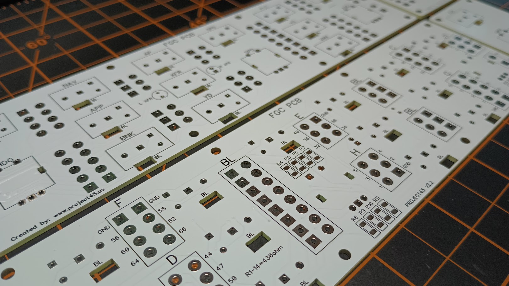
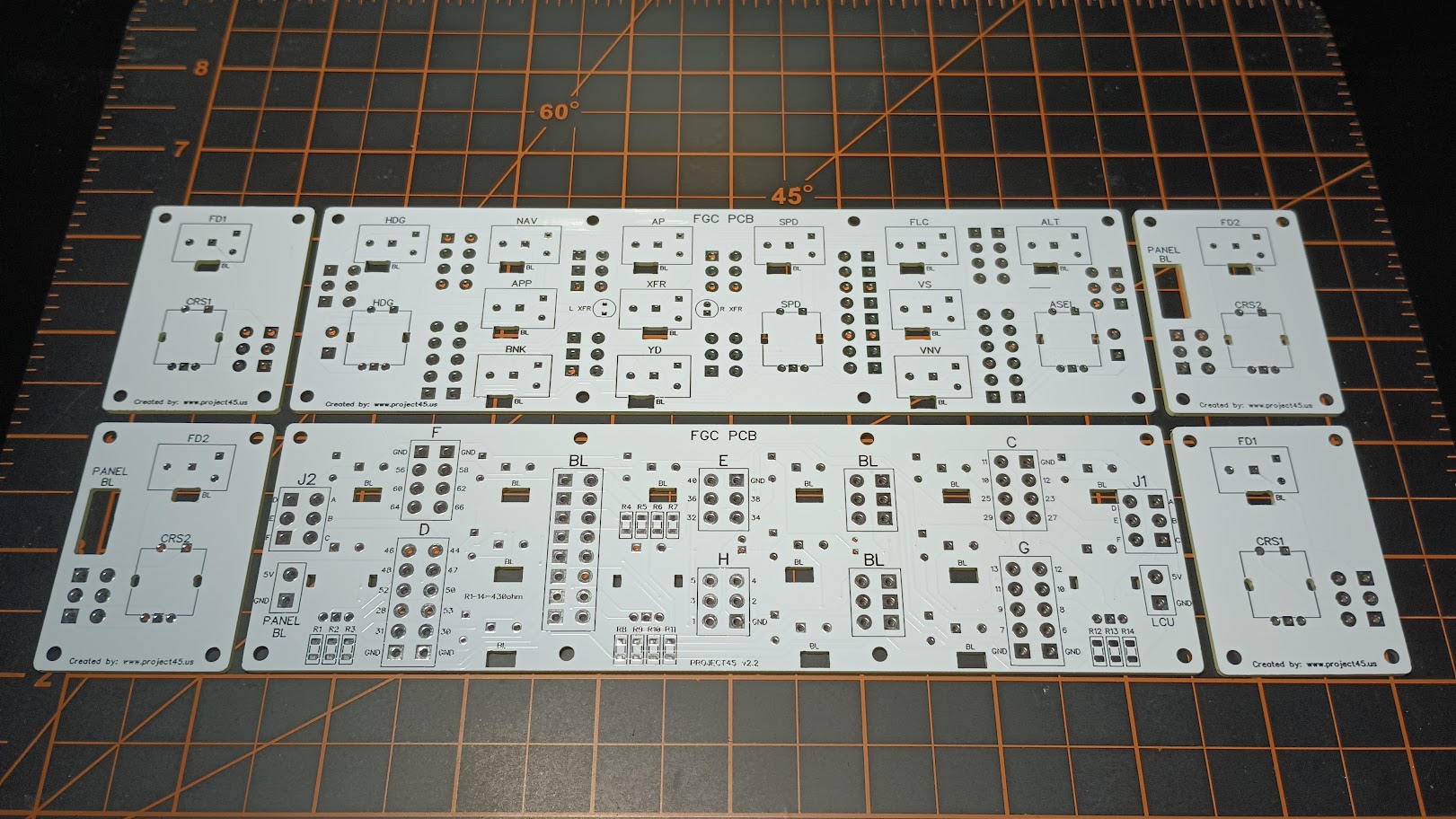
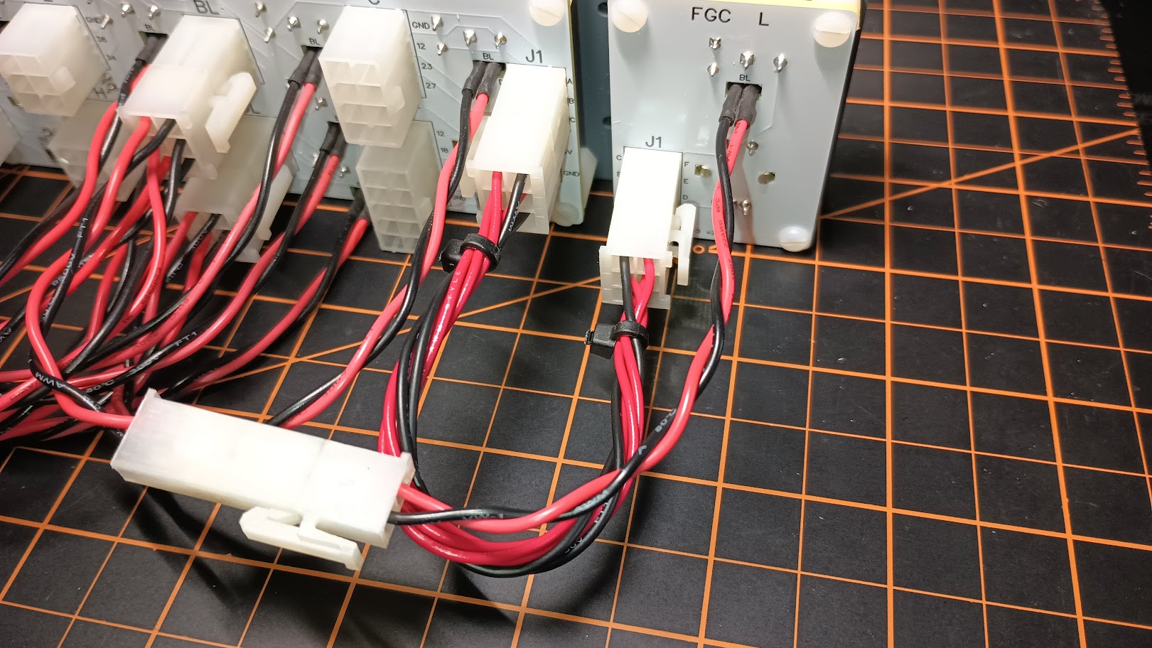
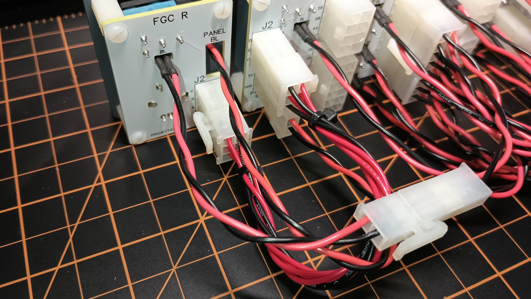
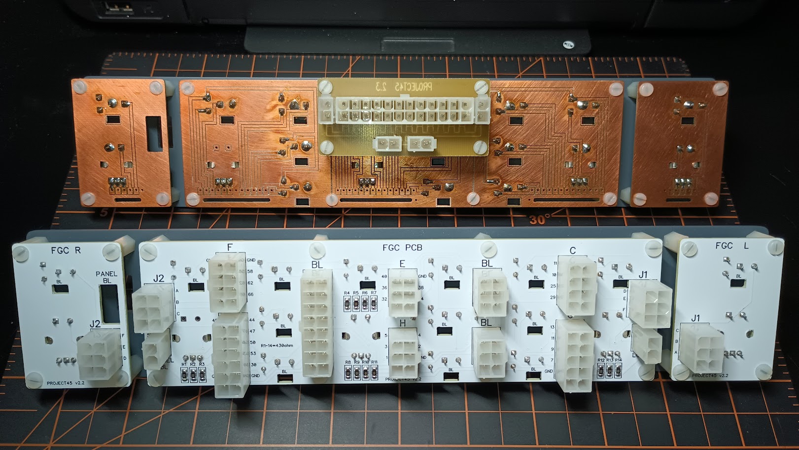
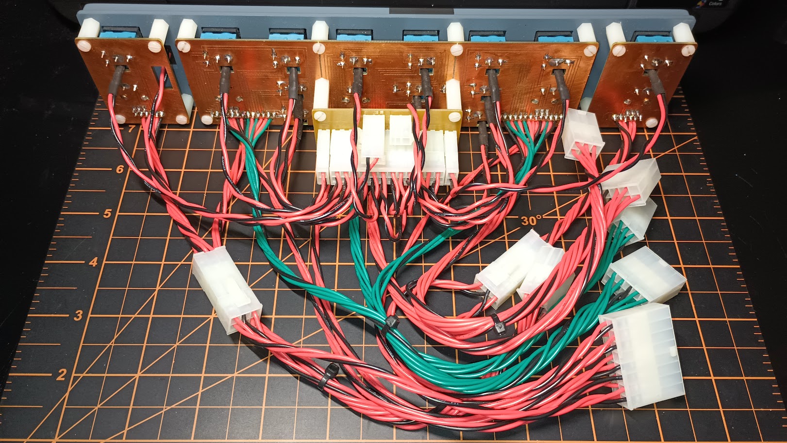
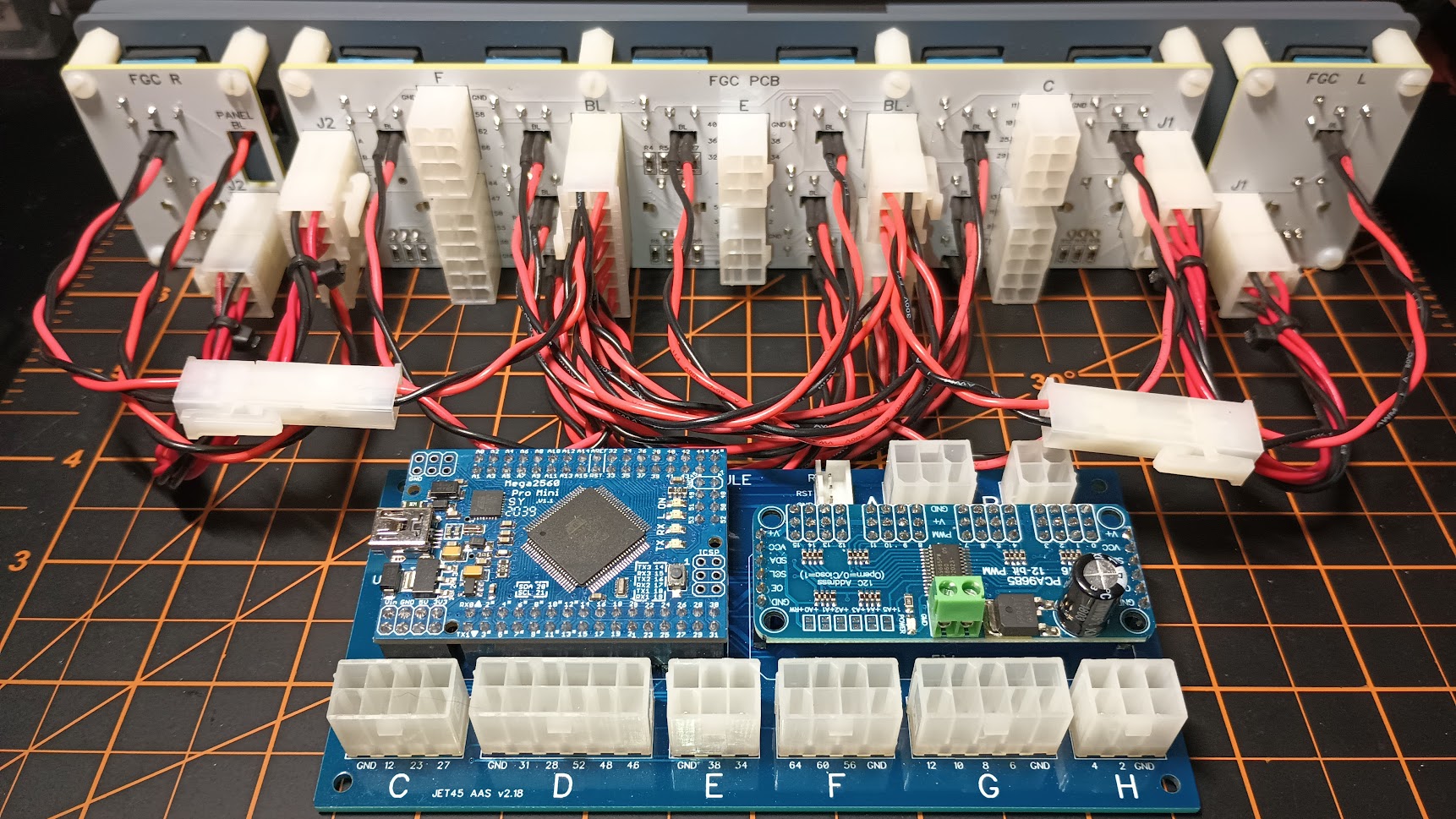
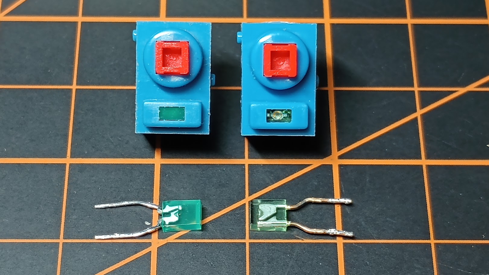
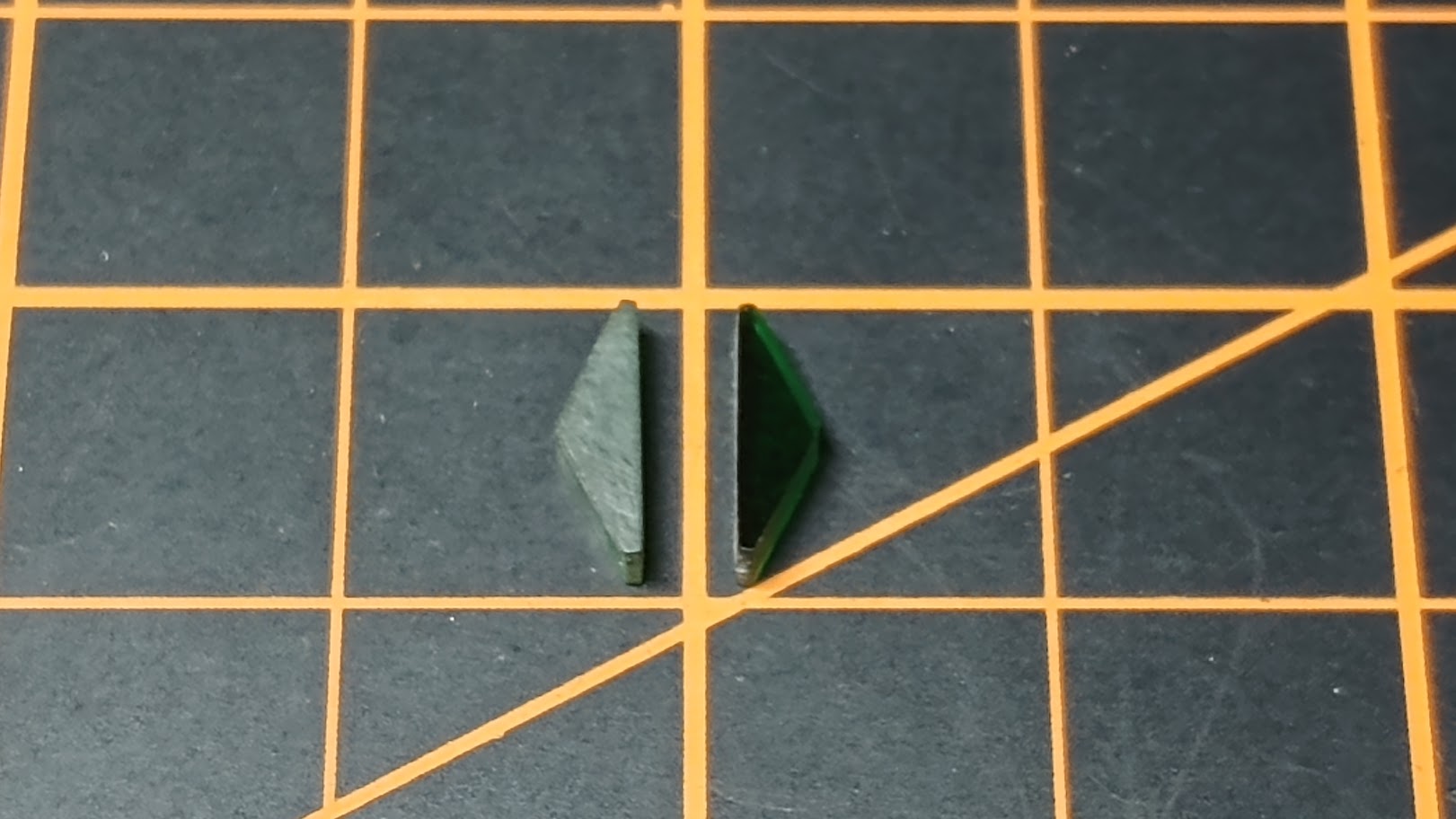
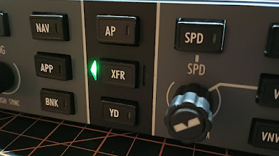
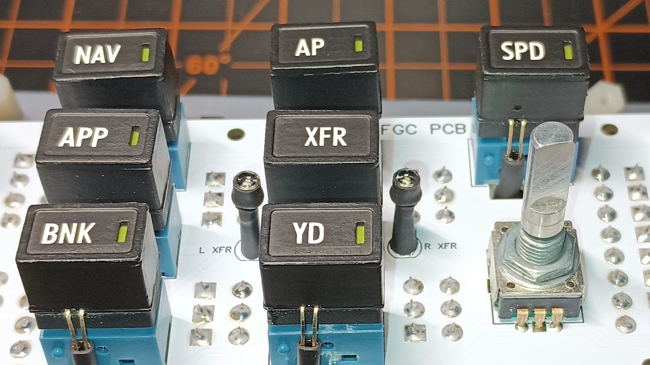
NEW FGC RELEASE! I have been hinting around that there is a better way to wire up the FGC in the works. Over the past 18 months I have become fairly proficient with pcb design which has me going back and looking at areas of our build that have been completed but could use some additional TLC. The FGC is one of those areas! First, the FGC clad version works great but it's difficult to manufacture the clad, solder and requires a lot of attention to create and build up the wiring harnesses. The end result is the FGC clad version works great once built up but it can be difficult to get to that point. But that has all changed for the better! The new FGC pcb design takes all the hard parts out of the buildup! Manufacturing the pcb is as easy as clicking a mouse. Soldering to pcb is 10 times easier than soldering to clad. Last but not least, building up a FGC pcb is as easy as one two three! (Some soldering required) The end result is the new FGC is 10 times easier to build up and works exactly the same as the FGC clad version. The goal is to make the FGC and all other panels in the Lear45 build as easy as possible to interface with Jason Hite's Jet45 v2.0 software. View the Jet45 AAS Systems Modules HERE Let me cover some of the finer details of the new FGC design. First, like most pcb, everything is labeled front and back with a silk layer to better identify the hardware and more importantly, the plugs and pins! Second, the button backlighting clad from the earlier design is now built into the main FGC pcb. You will notice there are 14 resistors pads and three BL (Back Lighting) plugs. The 14 BL wires can be plugged into any of the 14 BL pins, so long as you get the ground and the power lines oriented correctly. Third, the six plugs that come from the FGC Interface Module are now an exact match on the FGC pcb you see here! All the sorting and grouping has been done within the pcb, so all the end user has to do is build up straight one to one wiring harnesses. Forth, because of the way we mount the FGC to the Glare Shield, the FGC pcb is split in three pieces. (This might change in a future FGC) This requires a couple jumpers from the end pcb pieces to the main pcb. These are J1 and J2, see photos: (Depending on your web browser, you should be able to right click and "Open Image in New Tab" to get a super close look. I use Mozilla Firefox) If you order a Plug and Play FGC, these jumpers will be included. The thing to remember is that once you have them, you can't plug them in wrong. Flip them around, they work. Switch the jumpers from J1 to J2, they work. You can't plug the jumpers in wrong as long as they are assembled correctly to begin with! Last but not least, it's neat and clean. I still offer the FGC in the "Head Start" kit upon request. The photo below shows the comparison between the clad version and the new pcb version. If your are still fuzzy as to why the move to pcb? This one photo should clear things up! This is the back side of the old FGC "Plug and Play" clad version. What do all those pins and plugs go to? With a volt meter and a couple hours of time, everything can be sorted. With any great project, there will be progress and evolution! And this is the back side of the new FGC "Plug and Play" pcb with the FGC Module for illustration. Notice on the FGC Module that there are six plugs running along the bottom of the card? Those six plugs are also found on the FGC pcb. If you ordered a FGC "Plug and Play" pcb version, assembly instructions are as follows: Step 1: Create six wiring harnesses to match the plugs on the FGC Module that also match the plugs on the FGC pcb. NOTE: Insure the wiring harnesses are long enough to reach between the FGC Module and the FGC pcb! That's it! Any more instruction and I would be rambling on. Anyone who already has a FGC will get two free sets of FGC pcb to make the upgrade. (one spare) If you can desolder and solder, you will find that the conversion will take less than a couple hours. I have already done three, with one more to go! So far all the testing that I have done on the new FGC is passing. But we need to get a few of these out into your hands to do some in-depth testing to confirm what I am seeing is true. NOTE: The new FGC pcb upgrade is specifically designed to work with the new v2.0 Jet45 AAS software and modules. If you are not currently testing the new Jet45 software and modules, no worries, the new pcb design will still work in your build. (The new FGC pcb is also 100% compatible with the FDS SYS cards) For the record, the FGC from the Pilot's point of view is exactly the same! NEW FGC RELEASE! I have been hinting around that there is a better way to wire up the FGC in the works. Over the past 18 months I have become fairly proficient with pcb design which has me going back and looking at areas of our build that have been completed but could use some additional TLC. The FGC is one of those areas! First, the FGC clad version works great but it's difficult to manufacture the clad, solder and requires a lot of attention to create and build up the wiring harnesses. The end result is the FGC clad version works great once built up but it can be difficult to get to that point. But that has all changed for the better! The new FGC pcb design takes all the hard parts out of the buildup! Manufacturing the pcb is as easy as clicking a mouse. Soldering to pcb is 10 times easier than soldering to clad. Last but not least, building up a FGC pcb is as easy as one two three! (Some soldering required) The end result is the new FGC is 10 times easier to build up and works exactly the same as the FGC clad version. The goal is to make the FGC and all other panels in the Lear45 build as easy as possible to interface with Jason Hite's Jet45 v2.0 software. View the Jet45 AAS Systems Modules HERE Let me cover some of the finer details of the new FGC design. First, like most pcb, everything is labeled front and back with a silk layer to better identify the hardware and more importantly, the plugs and pins! Second, the button backlighting clad from the earlier design is now built into the main FGC pcb. You will notice there are 14 resistors pads and three BL (Back Lighting) plugs. The 14 BL wires can be plugged into any of the 14 BL pins, so long as you get the ground and the power lines oriented correctly. Third, the six plugs that come from the FGC Interface Module are now an exact match on the FGC pcb you see here! All the sorting and grouping has been done within the pcb, so all the end user has to do is build up straight one to one wiring harnesses. Forth, because of the way we mount the FGC to the Glare Shield, the FGC pcb is split in three pieces. (This might change in a future FGC) This requires a couple jumpers from the end pcb pieces to the main pcb. These are J1 and J2, see photos: (Depending on your web browser, you should be able to right click and "Open Image in New Tab" to get a super close look. I use Mozilla Firefox) If you order a Plug and Play FGC, these jumpers will be included. The thing to remember is that once you have them, you can't plug them in wrong. Flip them around, they work. Switch the jumpers from J1 to J2, they work. You can't plug the jumpers in wrong as long as they are assembled correctly to begin with! Last but not least, it's neat and clean. I still offer the FGC in the "Head Start" kit upon request. The photo below shows the comparison between the clad version and the new pcb version. If your are still fuzzy as to why the move to pcb? This one photo should clear things up! This is the back side of the old FGC "Plug and Play" clad version. What do all those pins and plugs go to? With a volt meter and a couple hours of time, everything can be sorted. With any great project, there will be progress and evolution! And this is the back side of the new FGC "Plug and Play" pcb with the FGC Module for illustration. Notice on the FGC Module that there are six plugs running along the bottom of the card? Those six plugs are also found on the FGC pcb. If you ordered a FGC "Plug and Play" pcb version, assembly instructions are as follows: Step 1: Create six wiring harnesses to match the plugs on the FGC Module that also match the plugs on the FGC pcb. NOTE: Insure the wiring harnesses are long enough to reach between the FGC Module and the FGC pcb! That's it! Any more instruction and I would be rambling on. Anyone who already has a FGC will get two free sets of FGC pcb to make the upgrade. (one spare) If you can desolder and solder, you will find that the conversion will take less than a couple hours. I have already done three, with one more to go! So far all the testing that I have done on the new FGC is passing. But we need to get a few of these out into your hands to do some in-depth testing to confirm what I am seeing is true. NOTE: The new FGC pcb upgrade is specifically designed to work with the new v2.0 Jet45 AAS software and modules. If you are not currently testing the new Jet45 software and modules, no worries, the new pcb design will still work in your build. (The new FGC pcb is also 100% compatible with the FDS SYS cards) For the record, the FGC from the Pilot's point of view is exactly the same! Thanks Roel! The FGC is one of my favorite panels to work on, probably because it is so complex and challenging. UPDATE: I do have an update in reference to the green indicator lights built into the Mountain switches and the L/R XFR lights. First the indicator LEDs built int the Mountain switches. I discovered that although the Mountain switches all have the same part number, 107-6612, there are two different types of green LEDs built into the switch. See photo: The color of the two LEDs are exactly the same, however, the intensity is different. The one on the left is not as bright as the one on the right. The Mountain switches as you know have become obsolete, so finding these is hard and now we have one more dynamic to work around, making sure the intensity of the green indicator lights match each other. I had a couple cases where I had to desolder a few switches from a FGC and replace them with matching Mountain switches. The brightness of the green LED coming up through the body of the switch cap is already on the dim side. If you have a choice, try to populate your FGC with the type pictured on the right, which is a little brighter. The main thing is try to make sure all the switches match. The second item that needed a little more attention is the XFR lenses. We referred to them a the "green jewels" back in the day. While the green LEDs in the Mountain switches are too dim, the LEDs in the L/R XFR are too bright. I had to add paper filters to the XFR LEDs and then scuff sand them front and back. The one on the left has already been sanded. The one on the right still needs sanding. The look of the real XFR lens is dark and almost black. Not green as you might expect. But no worries, in ambient light, the lenses appear to be dark in color. The XFR LEDs appear bright but not nearly as bright as they were prior to these minor changes. One last thing that you may have to do is add additional shrink tube to the LED legs. I found that even though the head of the LEDs are encased in shrink tube, green light is escaping through the bottom between the legs. This green light can potentially be seen around the button openings in the front panel. To fix this, simply add additional shrink tube down the entire length of the LED legs. Problem solved. If you are planning to update your FGC with the new FGC pcb, keep an eye out on these issues! If nothing else, now you know why some green indicators in your FGC appear brighter or dimmer than others. Thanks Roel! The FGC is one of my favorite panels to work on, probably because it is so complex and challenging. UPDATE: I do have an update in reference to the green indicator lights built into the Mountain switches and the L/R XFR lights. First the indicator LEDs built int the Mountain switches. I discovered that although the Mountain switches all have the same part number, 107-6612, there are two different types of green LEDs built into the switch. See photo: The color of the two LEDs are exactly the same, however, the intensity is different. The one on the left is not as bright as the one on the right. The Mountain switches as you know have become obsolete, so finding these is hard and now we have one more dynamic to work around, making sure the intensity of the green indicator lights match each other. I had a couple cases where I had to desolder a few switches from a FGC and replace them with matching Mountain switches. The brightness of the green LED coming up through the body of the switch cap is already on the dim side. If you have a choice, try to populate your FGC with the type pictured on the right, which is a little brighter. The main thing is try to make sure all the switches match. The second item that needed a little more attention is the XFR lenses. We referred to them a the "green jewels" back in the day. While the green LEDs in the Mountain switches are too dim, the LEDs in the L/R XFR are too bright. I had to add paper filters to the XFR LEDs and then scuff sand them front and back. The one on the left has already been sanded. The one on the right still needs sanding. The look of the real XFR lens is dark and almost black. Not green as you might expect. But no worries, in ambient light, the lenses appear to be dark in color. The XFR LEDs appear bright but not nearly as bright as they were prior to these minor changes. One last thing that you may have to do is add additional shrink tube to the LED legs. I found that even though the head of the LEDs are encased in shrink tube, green light is escaping through the bottom between the legs. This green light can potentially be seen around the button openings in the front panel. To fix this, simply add additional shrink tube down the entire length of the LED legs. Problem solved. If you are planning to update your FGC with the new FGC pcb, keep an eye out on these issues! If nothing else, now you know why some green indicators in your FGC appear brighter or dimmer than others.Flight Guidance Controller Discussion
![]()
![]()
![]()
2017-10-10