


(Original thread started on 08-27-13 by Eric Tomlin) Project 45 and Flight Line Simulations are pleased to announce the upcoming release of their Learjet 45-style Flight Guidance Controller. Flight Line and Project 45 have been working together for the past three months to co-develop a fully functional and accurate looking Flight Guidance Controller for the Learjet simulator community. The two have both received requests for the item ever since the beginning of both Flight Line (formally Flight Level Simulations) and Project45: Flight Line had already invested several weeks into both the front panel as well as the hardware+interface of the unit, but was not satisfied with the options for hardware available to the enthusiast-level marketplace. "Ron called me up one day and asked me if I had anything going on for the FGC and I told him that I had already designed and manufactured a front panel months ago, but that the options for accurate internal hardware was very limited and hard to find. It was then that he and I decided that it would be a great idea for him to push forward with the internals of the unit" said Eric Tomlin of Flight Line Simulations: The unit will be offered at three different price points. Each price point reflects the level of completion at time of shipping. In addition to the three price points, the Gen 2 front panel alone is available directly from Flight Line Simulations for $235.00. "We want to be able to offer folks the ability to choose to either sit down and completely assemble their own FGC at their leisure or to be able to buy a complete plug and play ready unit that is ready to be installed" said Ron Rollo of Project 45. Completed Flight Guidance Controller: The following prices are tentative and may be updated to reflect availability of hardware- 1. Flight Guidance Controller Kit $475: The FGC kit includes all of the major parts and components for the end user to complete the FGC in high detail. Kit includes: Flight Line Simulations™ Gen2 Back Lit Panel with with back lighting pigtail completely assembled Pre built 14 button pack set with laser engraved legends 4 copper clad pieces designed to handle FDS, Pokeys or Leo Bodanar interface cards 1 painted and tapped with 4-40 tap main backer panel 14 Mountain Switches with built in green indicator lights 5 rotary encoders with push option (one does not have push option) 5 temporary encoder knobs 40 Nylon 4-40 screws, standoffs and nuts 8 piece receptacle and plug set for back lighting circuit 32 piece male and female pin set for receptacles and plugs 14 warm white LEDs for back lighting the buttons 2 green LEDs for L and R XFR indicators 14 SMD resistors for button back lighting 2 green XFR jewels, tint and light filters (Kit does not include high detail replica encoder knobs) NOTE: There will be a FGC tutorial posted in this thread with detailed instructions of how the FGC will be completed. 2. Flight Guidance Controller Head Start Kit $575: The FGC Head Start Kit includes all of the parts listed above but included the following completed: Nylon standoffs cut to size and installed on the main backer panel All major components soldered onto the copper clad boards All SMD resistors and plugs soldered onto the back lighting circuit Install the green L and R XFR jewels, tint and light filters into the front panel Pop off the caps to the Mountain switches and remove the unwanted green jewels (Kit does not include high detail replica encoder knobs) Assemble all of the above into one unit 3. Flight Guidance Controller Plug and Play Version $975: The FGC Plug and Play Version is a complete unit ready to go including the wiring harnesses (Plug and Play version does not include high detail replica encoder knobs at this time) It should also be noted that FlightDeckSoft is working to have a JET45 Flight Guidance Controller software component available after the units begin shipping (which is not required for the units to work). NOTE: Future availability of the FGC as it has been designed here greatly depends on locating these switches: Mouser Part No. 107-6612 Click HERE for more information! For reference, this is the real deal! (Posted by Ron Rollo on 09-20-13) Here is a quick update on where we are at with the Flight Guidance Controllers. We are currently working on 15 separate sets. At this point all but two sets have been claimed. If you would like to reserve your FGC, please do so now by getting a hold of either myself or Eric Tomlin. Also, with the help of Eric G. and his 3D printer, we have come up with a very nice solution to the five encoder knobs. Thanks Eric G. for your work on this aspect of the build! Here is a quick photo of 13 sets about half way complete: UPDATE: Thanks to Eric G. we have FGC knobs! The main bodies were made with a 3D printer and the caps were done with a laser here locally in Jacksonville Florida. These will be made available with the FGC kits and the plug and play version: $45 for a set of five as pictured above. I know several of you already have the FGC knobs from Vince so the question is who needs knobs? I will also finish your knobs on request for an additional $20. This requires, filling, sanding, grinding and painting. For those guys who want the plug and play FGC, plan on adding another $65 to the price unless you already have Vince's knobs. To answer any questions about the drawing and some direction on the PCB: I will need to email everyone a copy of this so that you guys can blow it up and see it. The black lines are grounds, the red lines are switches or encoders and the the green lines are LEDs. I will have a tutorial as soon as we get ready to start sending the FGCs out. UPDATE: The work on the FGC's is moving forward. As a matter of fact a few sets have been mailed out and at least two more will be sent out in the next few days. Concerning the knobs. Eric G. was able to help fill the gap with the knobs with the use of his 3D printer. Most of you either have Vince's knobs or have asked me to complete your replica knobs made with the 3D printer. For those who are going to finish your knobs yourself, this is for you. Here is a photo of the FGC knob kit: CAUTION: I have already milled out the shaft slot so that it fits onto the encoder shaft perfectly snug and tight. You should not even need to use the set screw. Which brings me to this point. The way the knobs had to be made with the 3D printer leaves the inner area hollow or like a honeycomb pattern. The outside is solid and the area around the shaft slot is solid, but the area between the inside walls and the outside are hollow. What this means is you have to be careful about using the set screw. Consider the set screw that I have included and installed a small detail. Only use it if you find you need to. I found that there is enough material in the knob that the set screw can be used and is functional. However, I have to let you guys know about this because if you torque down on it, you will damage the knob: You will have to use a little spotting or glazing putty to fill in some gaps along the top: This is a photo of the laser engraved caps that come with the kit and will be installed onto the end of the knobs. But first, you have to put a beveled edge on four of the five. Note that four of the caps have a laser engraved guide line: You will need some double sided tape like this: Using a Dremel tool, you will place the caps on the Dremel using the tap. The laser engraved guide line will tell you if you have it perfectly centered or not when you spin it. If the circle is blurry, you need to adjust it. If it looks like a crisp clean circle while it is spinning, your ready to bevel the cap: How do you put a bevel on the cap you ask? Use a file and hold it at about a 45 degree angle. Be careful not to take too much off. Stop the Dremel and make sure your not taking too much off on one side. If so, finish the shaping by hand: You will end up with something like this. Remember, only four will be beveled. The fifth is going to sit fully into the top of the knob: Another photo from a low profile angle: Then just simply glue the caps into the top of the knobs. With a fine point paint brush paint the white beveled edge black to match the rest of the knob: For those who have ordered the finished knobs, you do not need to worry about most of this with the exception of being careful with the set screw. Next I will be posting a quick tutorial of how to bring the FGC kit to the Head Start package level. (Posted by Terry Collins on 11-01-13) I received Ron's portion of the FGC today. There has clearly been a lot of thought that has gone into the design and it looks so well made it could have come off a production line ! I'm looking forward to the tutorial to wire this baby up as I have no idea what still needs to be done to get it functional. (Original thread started on 08-27-13 by Eric Tomlin) Project 45 and Flight Line Simulations are pleased to announce the upcoming release of their Learjet 45-style Flight Guidance Controller. Flight Line and Project 45 have been working together for the past three months to co-develop a fully functional and accurate looking Flight Guidance Controller for the Learjet simulator community. The two have both received requests for the item ever since the beginning of both Flight Line (formally Flight Level Simulations) and Project45: Flight Line had already invested several weeks into both the front panel as well as the hardware+interface of the unit, but was not satisfied with the options for hardware available to the enthusiast-level marketplace. "Ron called me up one day and asked me if I had anything going on for the FGC and I told him that I had already designed and manufactured a front panel months ago, but that the options for accurate internal hardware was very limited and hard to find. It was then that he and I decided that it would be a great idea for him to push forward with the internals of the unit" said Eric Tomlin of Flight Line Simulations: The unit will be offered at three different price points. Each price point reflects the level of completion at time of shipping. In addition to the three price points, the Gen 2 front panel alone is available directly from Flight Line Simulations for $235.00. "We want to be able to offer folks the ability to choose to either sit down and completely assemble their own FGC at their leisure or to be able to buy a complete plug and play ready unit that is ready to be installed" said Ron Rollo of Project 45. Completed Flight Guidance Controller: The following prices are tentative and may be updated to reflect availability of hardware- 1. Flight Guidance Controller Kit $475: The FGC kit includes all of the major parts and components for the end user to complete the FGC in high detail. Kit includes: Flight Line Simulations™ Gen2 Back Lit Panel with with back lighting pigtail completely assembled Pre built 14 button pack set with laser engraved legends 4 copper clad pieces designed to handle FDS, Pokeys or Leo Bodanar interface cards 1 painted and tapped with 4-40 tap main backer panel 14 Mountain Switches with built in green indicator lights 5 rotary encoders with push option (one does not have push option) 5 temporary encoder knobs 40 Nylon 4-40 screws, standoffs and nuts 8 piece receptacle and plug set for back lighting circuit 32 piece male and female pin set for receptacles and plugs 14 warm white LEDs for back lighting the buttons 2 green LEDs for L and R XFR indicators 14 SMD resistors for button back lighting 2 green XFR jewels, tint and light filters (Kit does not include high detail replica encoder knobs) NOTE: There will be a FGC tutorial posted in this thread with detailed instructions of how the FGC will be completed. 2. Flight Guidance Controller Head Start Kit $575: The FGC Head Start Kit includes all of the parts listed above but included the following completed: Nylon standoffs cut to size and installed on the main backer panel All major components soldered onto the copper clad boards All SMD resistors and plugs soldered onto the back lighting circuit Install the green L and R XFR jewels, tint and light filters into the front panel Pop off the caps to the Mountain switches and remove the unwanted green jewels (Kit does not include high detail replica encoder knobs) Assemble all of the above into one unit 3. Flight Guidance Controller Plug and Play Version $975: The FGC Plug and Play Version is a complete unit ready to go including the wiring harnesses (Plug and Play version does not include high detail replica encoder knobs at this time) It should also be noted that FlightDeckSoft is working to have a JET45 Flight Guidance Controller software component available after the units begin shipping (which is not required for the units to work). NOTE: Future availability of the FGC as it has been designed here greatly depends on locating these switches: Mouser Part No. 107-6612 Click HERE for more information! For reference, this is the real deal! (Posted by Ron Rollo on 09-20-13) Here is a quick update on where we are at with the Flight Guidance Controllers. We are currently working on 15 separate sets. At this point all but two sets have been claimed. If you would like to reserve your FGC, please do so now by getting a hold of either myself or Eric Tomlin. Also, with the help of Eric G. and his 3D printer, we have come up with a very nice solution to the five encoder knobs. Thanks Eric G. for your work on this aspect of the build! Here is a quick photo of 13 sets about half way complete: UPDATE: Thanks to Eric G. we have FGC knobs! The main bodies were made with a 3D printer and the caps were done with a laser here locally in Jacksonville Florida. These will be made available with the FGC kits and the plug and play version: $45 for a set of five as pictured above. I know several of you already have the FGC knobs from Vince so the question is who needs knobs? I will also finish your knobs on request for an additional $20. This requires, filling, sanding, grinding and painting. For those guys who want the plug and play FGC, plan on adding another $65 to the price unless you already have Vince's knobs. To answer any questions about the drawing and some direction on the PCB: I will need to email everyone a copy of this so that you guys can blow it up and see it. The black lines are grounds, the red lines are switches or encoders and the the green lines are LEDs. I will have a tutorial as soon as we get ready to start sending the FGCs out. UPDATE: The work on the FGC's is moving forward. As a matter of fact a few sets have been mailed out and at least two more will be sent out in the next few days. Concerning the knobs. Eric G. was able to help fill the gap with the knobs with the use of his 3D printer. Most of you either have Vince's knobs or have asked me to complete your replica knobs made with the 3D printer. For those who are going to finish your knobs yourself, this is for you. Here is a photo of the FGC knob kit: CAUTION: I have already milled out the shaft slot so that it fits onto the encoder shaft perfectly snug and tight. You should not even need to use the set screw. Which brings me to this point. The way the knobs had to be made with the 3D printer leaves the inner area hollow or like a honeycomb pattern. The outside is solid and the area around the shaft slot is solid, but the area between the inside walls and the outside are hollow. What this means is you have to be careful about using the set screw. Consider the set screw that I have included and installed a small detail. Only use it if you find you need to. I found that there is enough material in the knob that the set screw can be used and is functional. However, I have to let you guys know about this because if you torque down on it, you will damage the knob: You will have to use a little spotting or glazing putty to fill in some gaps along the top: This is a photo of the laser engraved caps that come with the kit and will be installed onto the end of the knobs. But first, you have to put a beveled edge on four of the five. Note that four of the caps have a laser engraved guide line: You will need some double sided tape like this: Using a Dremel tool, you will place the caps on the Dremel using the tap. The laser engraved guide line will tell you if you have it perfectly centered or not when you spin it. If the circle is blurry, you need to adjust it. If it looks like a crisp clean circle while it is spinning, your ready to bevel the cap: How do you put a bevel on the cap you ask? Use a file and hold it at about a 45 degree angle. Be careful not to take too much off. Stop the Dremel and make sure your not taking too much off on one side. If so, finish the shaping by hand: You will end up with something like this. Remember, only four will be beveled. The fifth is going to sit fully into the top of the knob: Another photo from a low profile angle: Then just simply glue the caps into the top of the knobs. With a fine point paint brush paint the white beveled edge black to match the rest of the knob: For those who have ordered the finished knobs, you do not need to worry about most of this with the exception of being careful with the set screw. Next I will be posting a quick tutorial of how to bring the FGC kit to the Head Start package level. (Posted by Terry Collins on 11-01-13) I received Ron's portion of the FGC today. There has clearly been a lot of thought that has gone into the design and it looks so well made it could have come off a production line ! I'm looking forward to the tutorial to wire this baby up as I have no idea what still needs to be done to get it functional. (Posted by Ron Rollo on 11-04-13) FLIGHT GUIDANCE CONTROLLER TUTORIAL This is a tutorial of how to bring the FGC kit to the Head Start package level: The first thing that you will need to do is insure that all the trace lines are separated from the ground and from each other. You will need a volt meter, something like this one: (Before I send any of the parts out, I insure that they are good but please double check. It is much easier to find and identify a problem now rather than after you start soldering, trust me!) Let's start with the PCB light circuit. Basically it is designed so that only one 12 volt power line is needed from your power source and it will plug into this board. From there, the power is reduced down to about 3 volts using very small SMD (surface mounted device) resistors pictured below. (I have included a few extras in case you loose one or two.) After the current runs through the resistors, it will run to 14 separate LEDs that will be placed inside the push buttons. In addition to that, Eric Tomlin's front panel will also simply plug into this light circuit board: If you have elected to go with the kit version of the FGC, I should not have to show you how to solder right? I found it much easier to get all of the SMD resistors on the board first. Again, before you start, double check to make sure that all the traces are separated: After you get all the SMD resistors on the board, check to make sure that you have no cold solders and that the voltage does in fact drop on the other side. Once the resistors are squared away, you you can add the plugs with pins. Especially on the large one, make sure that the tab is facing away from the center of the board: This is the complete light circuit board: Now we are ready to move on to the main circuit board and it's wings: Once again, insure that all trace lines are clear and nothing is wrong. If you do find something bad, running a blade down the trace lines will clear the issue. (Usually it is just a tiny piece of copper clad dust making the connection from one side to the other.) Start with the buttons. You will see that they simply pop into the holes on the clad. The trick is flipping it upside down so you can solder. What I did was solder only one pin on each of the buttons so that I could flip it back over and double check that all four corners of each button was seated flush on the clad. If it's not, simply heat the pin with the soldering iron while pushing it down onto the clad. (You can't do this if you have more than one pin soldered on the same button.) Once your sure all four corners of all the buttons are seated properly, you can solder the remaining pins. The five encoders. Four of the five encoders have a push function on it which can be identified by the two additional pins. Take a look at the photo: The one encoder that does not have the push function will be soldered to the position that has those two pins isolated like in this photo: Because this encoder does not have the two additional pins, you might want to bind it's side legs over to help hold it in place like I have done in this photo above. One thing to be very careful about is that all four corner of the encoders is seated firmly to the clad. So the same thing goes here, solder one pin on each encoder at a time. If you need to adjust one, it is much easier when there is only one solder per encoder: Check your alignment and make sure they are pointed straight up and seated properly! At this point you should have all the the major components soldered to the three pieces of clad: Take a minute to make sure you do not have any cold solders and that none of your trace lines are compromised. Now it's time to address the two green transfer LEDs: You can identify them by the shrink wrap around the head of the LEDs. I did this to help reduce the chance of light bleed into any other part of the FGC. (The shorter lead on the LED is the ground.) Carefully temporarily assemble the FGC body including the two green LEDs. The ground trace is the one that shares several other grounds. The power trace is isolated and does not share with anything: After you get it assembled, put a couple nylon screws in it to hold it together. You have to do it this way so that you know what the exact height of the LED leads are. Cut off the extra leads on the LEDs but make sure you leave enough to solder to. Here is a photo of the LEDs soldered onto the clad: Prior to putting it all together, you might as well take a minute to pop off the caps to the buttons and remove the green jewels inside the caps. (The green jewel needs to be removed to allow as much light from the green LEDs to pass through the switch/cap as possible: The caps just pop off. Figure one out and the rest will follow. Find a tool that is appropriate and push out the jewels (small green plastic pieces): Now to put everything together to see what we have so far. Find two Nylon standoffs and two Nylon nuts: These will go in the middle two holes. You might have to trim one side of one of the Nylon standoffs so that it does not interfere with a solder point. (You will see what I am talking about.): Use the other two standoffs to attach the light circuit. Then use all the Nylon screws to tie it all together: You should have something that looks like this: If you do, your FGC is now at the "Head Start" package point. Congrats! (Posted by Ron Rollo on 11-04-13) FLIGHT GUIDANCE CONTROLLER TUTORIAL This is a tutorial of how to bring the FGC kit to the Head Start package level: The first thing that you will need to do is insure that all the trace lines are separated from the ground and from each other. You will need a volt meter, something like this one: (Before I send any of the parts out, I insure that they are good but please double check. It is much easier to find and identify a problem now rather than after you start soldering, trust me!) Let's start with the PCB light circuit. Basically it is designed so that only one 12 volt power line is needed from your power source and it will plug into this board. From there, the power is reduced down to about 3 volts using very small SMD (surface mounted device) resistors pictured below. (I have included a few extras in case you loose one or two.) After the current runs through the resistors, it will run to 14 separate LEDs that will be placed inside the push buttons. In addition to that, Eric Tomlin's front panel will also simply plug into this light circuit board: If you have elected to go with the kit version of the FGC, I should not have to show you how to solder right? I found it much easier to get all of the SMD resistors on the board first. Again, before you start, double check to make sure that all the traces are separated: After you get all the SMD resistors on the board, check to make sure that you have no cold solders and that the voltage does in fact drop on the other side. Once the resistors are squared away, you you can add the plugs with pins. Especially on the large one, make sure that the tab is facing away from the center of the board: This is the complete light circuit board: Now we are ready to move on to the main circuit board and it's wings: Once again, insure that all trace lines are clear and nothing is wrong. If you do find something bad, running a blade down the trace lines will clear the issue. (Usually it is just a tiny piece of copper clad dust making the connection from one side to the other.) Start with the buttons. You will see that they simply pop into the holes on the clad. The trick is flipping it upside down so you can solder. What I did was solder only one pin on each of the buttons so that I could flip it back over and double check that all four corners of each button was seated flush on the clad. If it's not, simply heat the pin with the soldering iron while pushing it down onto the clad. (You can't do this if you have more than one pin soldered on the same button.) Once your sure all four corners of all the buttons are seated properly, you can solder the remaining pins. The five encoders. Four of the five encoders have a push function on it which can be identified by the two additional pins. Take a look at the photo: The one encoder that does not have the push function will be soldered to the position that has those two pins isolated like in this photo: Because this encoder does not have the two additional pins, you might want to bind it's side legs over to help hold it in place like I have done in this photo above. One thing to be very careful about is that all four corner of the encoders is seated firmly to the clad. So the same thing goes here, solder one pin on each encoder at a time. If you need to adjust one, it is much easier when there is only one solder per encoder: Check your alignment and make sure they are pointed straight up and seated properly! At this point you should have all the the major components soldered to the three pieces of clad: Take a minute to make sure you do not have any cold solders and that none of your trace lines are compromised. Now it's time to address the two green transfer LEDs: You can identify them by the shrink wrap around the head of the LEDs. I did this to help reduce the chance of light bleed into any other part of the FGC. (The shorter lead on the LED is the ground.) Carefully temporarily assemble the FGC body including the two green LEDs. The ground trace is the one that shares several other grounds. The power trace is isolated and does not share with anything: After you get it assembled, put a couple nylon screws in it to hold it together. You have to do it this way so that you know what the exact height of the LED leads are. Cut off the extra leads on the LEDs but make sure you leave enough to solder to. Here is a photo of the LEDs soldered onto the clad: Prior to putting it all together, you might as well take a minute to pop off the caps to the buttons and remove the green jewels inside the caps. (The green jewel needs to be removed to allow as much light from the green LEDs to pass through the switch/cap as possible: The caps just pop off. Figure one out and the rest will follow. Find a tool that is appropriate and push out the jewels (small green plastic pieces): Now to put everything together to see what we have so far. Find two Nylon standoffs and two Nylon nuts: These will go in the middle two holes. You might have to trim one side of one of the Nylon standoffs so that it does not interfere with a solder point. (You will see what I am talking about.): Use the other two standoffs to attach the light circuit. Then use all the Nylon screws to tie it all together: You should have something that looks like this: If you do, your FGC is now at the "Head Start" package point. Congrats! The biggest challenge for me is to try to explain the trace lines on the three main clad boards. First off, let me say that the way this FGC has been designed is so that it will work with any known interface card. I am using the FDS cards for all the push buttons and LEDs. I am using the Pokeys interface card for the five encoders. Everything or I should say all the major groups are isolated from each other to give you flexibility in what you want to do. It adds a few extra ground line but removes several headaches! I posted this up earlier in this thread but now that we are getting ready to do something, here it is again: I use three colors for my wiring. Black is always a ground or common line. Red is always a switch or power line. And green is always an LED line. This way I can quickly identify what a group of wires are for. (Unlike a real Lear45 where everything is white.) Groups: 1. Each encoder is isolated, even isolated from each other! 2. There are five ground sections of clad. The two wing clads are obviously isolated. The main center piece of clad has two isolation lines that break it up into three section (giving you a total of five sections). The reason I had to do this was to satisfy the FDS cards. Remember that they are 8 to 1, meaning that for every eight inputs or outputs, they share one common ground. 3. The push button switches are in sets of less than eight. (The push buttons on the end of the encoders are also in this group) 4. The green LED indicators are in groups of less than eight. (The two green transfer LEDs soldered to the clad are also in this group) Eleven of the fourteen push buttons have a green LED. (FD1, FD2 and the XFR do not have a green LED) 5. The button cap back lighting. All fourteen bush buttons get back lighting. These are all powered via a 12 volt supply but using resistors drops the power down to about 3 volts. All the button lighting is routed to the light clad that is mounted higher than the other three pieces. You might notice that there are fourteen holes in the clad that the wires to the button lighting will pass through. Take a look at the left and right clad. These are very simple and will help you understand the larger piece. You should be able to clearly pick out the encoder trace lines. There are three of them. The middle is going to be your ground (black) and the other two lines will be signal lines, (red). There are two other trace lines that go to the push function of the encoder and the push function of the push switch. Both of these lines will be red because they are switch lines. Last but not least, these two switch lines need a common ground. You will find a small hole that you will tie another black line into that will be your common ground. Remember, there are no green indicator lights in these two push buttons on the ends. Once you have these six lines soldered to the clad, route them through the long opening. For now, you should make everything coming off of the clad about eight inches long. Soldering to the clad is just the beginning! The next level is to group things together by using plugs and receptacles. Moving on to the center piece of clad. Remember, the center piece is divided up into three ground sections! Start by identifying the three encoders, one in each section. Follow the same rules as above. Each one will have two red lines and one black line. That's easy right? Next, each section will have two ground lines, one for the green indicator LEDs and one for the push switches. (Three ground lines if you want to include the encoder) So your next task is to identify the two grounds. The first one is easy. It's the hole sitting there with no trace line running to it and it is for the push switches.) The second ground line is the trace line that is sharing multiple places to tie into it. This trace line is for the green indicator LEDs that are mounted inside the switches. (They also include the two green transfer LEDs.) Again, these two lines per section will be black. Now we can work on the green lines. This should be fairly easy as well to identify. You can do this by following the LED ground trace that shares mentioned above. In each place that the common ground line for the LEDs stops is the second half of the LEDs. These trace lines are the signal side of the LED and those lines will be green. (Notice that in no case that the total amount per group exceeds eight.) Last but not least, you should have nothing left on the center clad but red switch lines for the push buttons. Again, each of the three sections will have no more than eight to make the FDS cards happy. This photo below shows what you should have after grouping the sets. I also added my plugs: Although in this photo, I forgot to add a couple breakaway plugs for the wings so that it could be slipped into the glare shield. This photo is getting way ahead of what we are doing but to make the point about the wings needing breakaway plugs, take a look at this: Now to change gears and work on the 14 buttons and laser engraved caps. The Mountain switches are the perfect size for the push buttons and they even come equipped with the green LED off to the one side. The three key elements that it was missing is the height, the laser engraved legends on the face and last but not least the back lighting LED that illuminates the laser engraving. I have been able to address each of these issues that will give us all a button that will look and operate just like the real deal. Here is a photo of what I call the button pack: It might look neat but the real reason for the button pack is so that the laser engraving process is easier. In other words, all fourteen caps are engraved at the same time. In addition to this, you might notice that there is gold filter paper inside the large cavities and green filter paper in the smaller cavities. Furthermore, there is even reflective aluminum tape inside the green light chamber to help direct the light from the green LED in the switch to make it's way up to the cap face. (The green LEDs in the switches are not as bright as I would like but the reflective aluminum tape and removing the green plastic jewels addresses this) So the first thing your going to do is break apart this beautiful button cap registry: Then your going to sand off the spurs on all four sides with a file. Next you will need to use your blue painters tape to tape off the faces of the caps because the sides of the cap bodies need a few coats of paint to control the light bleed: I find that setting the caps at near 45 degree angles helps to insure that a good coat of paint gets on all four side: Next, each of the fourteen white LEDs need to be worked into the cap bodies. (This is one of the parts that I would consider unconventional) The LEDs will need to have two 90 degree bends in them and a small notch filed into the bottom edge of the caps for the LED leads: Notice the notch that has been filed into the cap? Take your time with this process because your going to want to get it right. Furthermore, you have to be careful when bending the LEDs. Bending LEDs close to the head could damage them. The good news is so far, the ones I have done I have enjoyed 100% success! Your next step is to take the LEDs that have been bent and solder your wires to them. I use red and black here. The shorter lead is the ground which is black: (I use red for these LEDs because this is back lighting and the original source of power will be a 12 volt power supply) Using typical Super Glue, assemble the three pieces you see here: This is your new laser engraved back lit button cap with green indicator light: This is all fourteen of them! Now that you have the button cap assembles complete, it is as simple as threading the two wires through the holes on the clad and popping the caps on the switch like this single one here: Here is a photo of all the caps popped onto the switches looking good! CAUTION: Make sure that your shrink tube run up the LED legs far enough that there is no way it will ever touch the clad board that it passes through. If either LED leg touches the clad (which is the common ground for the switches) it WILL damage the FDS SYS board! Next you will want to add the pins to the ends of the wires coming from the switch cap back lighting: Also, take note of the plugs that are required for the wing clads. You have to have these plugs to get the FGC in and out of the aluminum glare shield. If your not sure what I am talking about, just try to put the FGC in the glare shield and it will be clear. Your pretty much ready to add Eric's front panel to the FGC. There is a small back lighting pig tail that you will have to solder and add a plug to so that it will plug into the light clad: Making the wiring harnesses that go back to the interface cards is pretty much straight forward. Once you get those complete, your ready to install the FGC in the glare shield: Add the FGC knobs that you either ordered in kit form or complete: And you have complete the hardware part of your FGC! Your ready to interface your FGC! I may add a photo or two here and there when I get started on the next plug and play version. If you have any questions please feel free to post in this thread. The biggest challenge for me is to try to explain the trace lines on the three main clad boards. First off, let me say that the way this FGC has been designed is so that it will work with any known interface card. I am using the FDS cards for all the push buttons and LEDs. I am using the Pokeys interface card for the five encoders. Everything or I should say all the major groups are isolated from each other to give you flexibility in what you want to do. It adds a few extra ground line but removes several headaches! I posted this up earlier in this thread but now that we are getting ready to do something, here it is again: I use three colors for my wiring. Black is always a ground or common line. Red is always a switch or power line. And green is always an LED line. This way I can quickly identify what a group of wires are for. (Unlike a real Lear45 where everything is white.) Groups: 1. Each encoder is isolated, even isolated from each other! 2. There are five ground sections of clad. The two wing clads are obviously isolated. The main center piece of clad has two isolation lines that break it up into three section (giving you a total of five sections). The reason I had to do this was to satisfy the FDS cards. Remember that they are 8 to 1, meaning that for every eight inputs or outputs, they share one common ground. 3. The push button switches are in sets of less than eight. (The push buttons on the end of the encoders are also in this group) 4. The green LED indicators are in groups of less than eight. (The two green transfer LEDs soldered to the clad are also in this group) Eleven of the fourteen push buttons have a green LED. (FD1, FD2 and the XFR do not have a green LED) 5. The button cap back lighting. All fourteen bush buttons get back lighting. These are all powered via a 12 volt supply but using resistors drops the power down to about 3 volts. All the button lighting is routed to the light clad that is mounted higher than the other three pieces. You might notice that there are fourteen holes in the clad that the wires to the button lighting will pass through. Take a look at the left and right clad. These are very simple and will help you understand the larger piece. You should be able to clearly pick out the encoder trace lines. There are three of them. The middle is going to be your ground (black) and the other two lines will be signal lines, (red). There are two other trace lines that go to the push function of the encoder and the push function of the push switch. Both of these lines will be red because they are switch lines. Last but not least, these two switch lines need a common ground. You will find a small hole that you will tie another black line into that will be your common ground. Remember, there are no green indicator lights in these two push buttons on the ends. Once you have these six lines soldered to the clad, route them through the long opening. For now, you should make everything coming off of the clad about eight inches long. Soldering to the clad is just the beginning! The next level is to group things together by using plugs and receptacles. Moving on to the center piece of clad. Remember, the center piece is divided up into three ground sections! Start by identifying the three encoders, one in each section. Follow the same rules as above. Each one will have two red lines and one black line. That's easy right? Next, each section will have two ground lines, one for the green indicator LEDs and one for the push switches. (Three ground lines if you want to include the encoder) So your next task is to identify the two grounds. The first one is easy. It's the hole sitting there with no trace line running to it and it is for the push switches.) The second ground line is the trace line that is sharing multiple places to tie into it. This trace line is for the green indicator LEDs that are mounted inside the switches. (They also include the two green transfer LEDs.) Again, these two lines per section will be black. Now we can work on the green lines. This should be fairly easy as well to identify. You can do this by following the LED ground trace that shares mentioned above. In each place that the common ground line for the LEDs stops is the second half of the LEDs. These trace lines are the signal side of the LED and those lines will be green. (Notice that in no case that the total amount per group exceeds eight.) Last but not least, you should have nothing left on the center clad but red switch lines for the push buttons. Again, each of the three sections will have no more than eight to make the FDS cards happy. This photo below shows what you should have after grouping the sets. I also added my plugs: Although in this photo, I forgot to add a couple breakaway plugs for the wings so that it could be slipped into the glare shield. This photo is getting way ahead of what we are doing but to make the point about the wings needing breakaway plugs, take a look at this: Now to change gears and work on the 14 buttons and laser engraved caps. The Mountain switches are the perfect size for the push buttons and they even come equipped with the green LED off to the one side. The three key elements that it was missing is the height, the laser engraved legends on the face and last but not least the back lighting LED that illuminates the laser engraving. I have been able to address each of these issues that will give us all a button that will look and operate just like the real deal. Here is a photo of what I call the button pack: It might look neat but the real reason for the button pack is so that the laser engraving process is easier. In other words, all fourteen caps are engraved at the same time. In addition to this, you might notice that there is gold filter paper inside the large cavities and green filter paper in the smaller cavities. Furthermore, there is even reflective aluminum tape inside the green light chamber to help direct the light from the green LED in the switch to make it's way up to the cap face. (The green LEDs in the switches are not as bright as I would like but the reflective aluminum tape and removing the green plastic jewels addresses this) So the first thing your going to do is break apart this beautiful button cap registry: Then your going to sand off the spurs on all four sides with a file. Next you will need to use your blue painters tape to tape off the faces of the caps because the sides of the cap bodies need a few coats of paint to control the light bleed: I find that setting the caps at near 45 degree angles helps to insure that a good coat of paint gets on all four side: Next, each of the fourteen white LEDs need to be worked into the cap bodies. (This is one of the parts that I would consider unconventional) The LEDs will need to have two 90 degree bends in them and a small notch filed into the bottom edge of the caps for the LED leads: Notice the notch that has been filed into the cap? Take your time with this process because your going to want to get it right. Furthermore, you have to be careful when bending the LEDs. Bending LEDs close to the head could damage them. The good news is so far, the ones I have done I have enjoyed 100% success! Your next step is to take the LEDs that have been bent and solder your wires to them. I use red and black here. The shorter lead is the ground which is black: (I use red for these LEDs because this is back lighting and the original source of power will be a 12 volt power supply) Using typical Super Glue, assemble the three pieces you see here: This is your new laser engraved back lit button cap with green indicator light: This is all fourteen of them! Now that you have the button cap assembles complete, it is as simple as threading the two wires through the holes on the clad and popping the caps on the switch like this single one here: Here is a photo of all the caps popped onto the switches looking good! CAUTION: Make sure that your shrink tube run up the LED legs far enough that there is no way it will ever touch the clad board that it passes through. If either LED leg touches the clad (which is the common ground for the switches) it WILL damage the FDS SYS board! Next you will want to add the pins to the ends of the wires coming from the switch cap back lighting: Also, take note of the plugs that are required for the wing clads. You have to have these plugs to get the FGC in and out of the aluminum glare shield. If your not sure what I am talking about, just try to put the FGC in the glare shield and it will be clear. Your pretty much ready to add Eric's front panel to the FGC. There is a small back lighting pig tail that you will have to solder and add a plug to so that it will plug into the light clad: Making the wiring harnesses that go back to the interface cards is pretty much straight forward. Once you get those complete, your ready to install the FGC in the glare shield: Add the FGC knobs that you either ordered in kit form or complete: And you have complete the hardware part of your FGC! Your ready to interface your FGC! I may add a photo or two here and there when I get started on the next plug and play version. If you have any questions please feel free to post in this thread. (Posted by Will Sasse on 04-16-14) Quick tip on super glues, keep them in the fridge - they last a lot longer. Randy, a nice tip on cutting the slot, I am up to that part myself and was going to use the side of a twist-drill. Now another tip on how to file the edges of the button caps. Most of us have a Dremel tool. One of the attachments is a 1/2" sanding drum. Undo the lock screw and remove the sanding drum: The button cap fits in the cutout for the washer, its a tight fit so a good push is required: Spin it against your file and jobs done! CAUTION: Don't use too much pressure as there is only friction holding the rubber drum to the shaft, and angle your file into the tool so that it doesn't climb off the shaft! So far that is the only new idea, everything else is going together just like Ron's tutorial says. UPDATE: Here is a photo of the rear (the front looks the same as Ron's photos) Grey wires are the button backlights, green wires = encoders, red wires = switch LED, white wires = switch. Nicely done Ron & Eric, went together as advertised. The only head-scratcher was the two triangular green jewels that I had no idea where they went. Finally worked it out - they go in Eric's front panel. Had to remove the back-plate to get them in. Easy to do, just not mentioned anywhere, till now! (Posted by Ron Rollo on 04-19-14) Looks great Will! Sorry about the not mentioning of the green jewels. I also included some tint for those jewels so that you can tone the intensity down if you want. I found that two layers of tint does the job to satisfy my liking. Thank you for the kind words and posting up a photo of your work! (Posted by Will Saase on 05-03-14) I presume that the FGC works with already modeled functions in FSX, no add-on program required. Whilst I'm here, further thoughts and tips: - don't cut out the thin bars from the MIP eyebrow, that is the only place to secure the FGC in place. Fortunately I worked this out in time....saved me from a serious oops! - If you have a standard LED color for your build already, swap before you build, not after. Don't ask me how I came to this conclusion! - solder LED backlight (3mm flat-top ones inserted into the cap via the unorthodox method) power wires to the LED's. I used female PCB pins sockets, they are extremely difficult to put back on if they fall off after the FGC is fully assembled. Solder rarely accidentally comes off! - heat shrink only one of the legs of the above LED, otherwise it compromises the smooth use of the push-button LED lead through the hole in the PCB. I am currently making the above adjustments, still not plugged in.... Its one of those days I wished I'd bought the plug-n-play version! (Posted by Eric Tomlin on 05-05-14) An FGC software has been in the works for a while now but currently on hold until the CDU software makes a bit more progress. As mentioned above, the FGC will absolutely work with the default FS/FSX/P3D AP because after all, it is only a piece of hardware that you connect to the PC via your interface (and in this case, The System Card from FDS + whatever card that you use that supports encoders, such as PoKeys). The FGC software will simplify and make more realistic the interfacing/operation of the FGC but again is absolutely not required for operation. (Posted by Mark Speechley on 05-25-14) Hi all, I've installed my FGC and looks great ( thanks Ron & Eric) however Randy and Will have hinted at the elephant in the room with regards to its functionality. I have come to a screeching halt with the old FSUIPC/encoder/offset 'black art' procedure. I have Alan's wonderful treatise on RMU encoder installation for Pokeys and FSUIPC. However it doesn't translate to the FGC due to obviously different offsets. I have looked at the FSUIPC list of offsets but it was guessing all the way to find that I couldn't get it to work. Could some one please tell me the settings/offsets we require to get the FGC encoders functional using FSUIPC please? At least keep us flying till the new Jet45 program arrives. By the way, my HDG button gets stuck inwards but will get back into Interface IT and see if it is recognized. Maybe only small travel of button still registers. (Posted by Will Sasse on 05-25-14) If you have buttons that get stuck when pushed, check the clearance of the backlight LED lead wires and Ron's backer panel. If its too tight, take your smallest screwdriver and push the wires in towards the switch body. Failing that, check the clearance of the wires attached to the LED where they pass through the PCB. No magic cure for that one so I hope it isn't the problem. I had both these problems when I first built the kit. If only I'd followed the instructions first time! Anyway, I replaced the LED's with warm-whites, and used much finer wires. Everything works beautifully now. (Posted by Ron Rollo on 05-26-14) Hey Mark, to answer your first question, I do not have the encoder offsets handy right this second but I will get them soon. As for the sticking buttons, it is normal to have one or two at first. Because of the nature the FGC had to be designed and built, the wires for each individual button's back lighting has to pass through the PCB board. (This was not the first choice to design and build something like this but because of the complexity of each button with two LEDs in them and the lack of products that would easily meet our requirements, this part of the build required some serious thinking outside of the box.) Anyway, once you have the FGC mounted in your glareshield, you might have to "maneuver" the wires to that sticky button until it no longer sticks. In other words, the wires to that button need to find it's "happy place" to lay in behind and through the PCB. Once the "happy place" is found and the only thing that is touched is the button face which only travels a fraction of an inch, you will not have anymore issues with it. At least until you pull the FGC out and mess with the karma of the wires again. I know this sounds ridiculous but this is the best answer I can give you to resolve the issue. But I can promise you this, your not alone and it is resolvable. (Posted by Mark Speechley on 05-27-14) No worries at all this end. Will inspect the anatomy (chiropractor coming out in me) of the switch from behind and see what you are talking about and have a 'whirl' at fixing it. I had the luxury of it pre-made so didn't get to see the meat and potatoes of the build. I'll review your tutorial for everyone else utilizing the kit form. (Posted by Ron Rollo on 05-27-14) That's funny you say the "Chiropractor in you", because that is exactly what it needs, a little adjusting. I apologize that we even need to do such a thing but it was "the best bad idea we had"! (Argo the movie) As for the Offset part of your question: I did not find this process fun or easy compared to the simple process of assigning a switch or a push button in InterfaceIT using the FDS cards. But unfortunately, the FDS cards do not support rotary encoders like the five that we have on the FGC panel. So what you will have to do is use a Pokeys card or a Leo Bodnar card that supports encoders. As you should know, there are three wires that come off of each encoder, one is a common (ground) and the other two are to collect inputs as you turn the encoder one way or the other. This is why if you take a close look at how I designed the wiring you will find that all five encoders are isolated from the other switch functions that the FDS cards will handle. Once you have all of your encoder wires wired up to your encoder friendly interface card then you will need to create a key stroke assignment for each encoder turn. In the case of the FGC, there will be 10 key stroke assignments. TIP: Because your NOT building a desktop sim and you will be using very little key strokes from the actual keyboard, it is recommended to delete ALL key stroke assignments in FSX so that you do not end up with conflicting key stroke assignments. But with that said, and before you do that, make a list of the ones that you do use and reassign them. As an example, I use the ZOOM in and ZOOM out key strokes a lot to adjust my visual system. ESC to exit the sim and PAUSE. As I am typing this I am having a hard time thinking of anything else that I use from the key board which shows you how much you will not need any of these assignments! To get back on task, I use the Pokeys56U, http://www.poscope.com/PoKeys56U (The "U" means that it is a USB connection.) You will need to assign each of the encoder selections (left and then right) a key stroke assignment. If you look closely you can see that there are 10 assignments. You can use any key stroke you want just as long as it is not already being used for another assignment: Now at this point, you should have the hardware in place and the encoders assigned to key strokes, but you do not have those key strokes assigned to do anything yet. That is the next step in the process which brings me to this point: There are no FSUIPC offsets like you are use to using within InterfaceIT. Here you will open FSUIPC within FSX while it is running and open the KEY PRESS window. In there you will be working with the SET button and "control sent when key pressed" selection bar. In this photo below, I am assigning CTL G to the AP VS VAR DEC offset. (Autopilot vertical speed variable decent). Once you hit SET, you will turn an encoder one direction only which will identify that selection as a key stroke (CTL G) as an example. Then you will go through your drop down list and find the FSUIPC assignment you want CTL G to control. Hit OK and that will save your new selections. And that is it in a nut shell. If you figure this out within an hour your a genius. Greg Branch and I struggled with this for some time until we finally cracked it. But with that said, this information will help steer you in the right direction. Your going to feel like a blind squirrel until you get the hang of this. I still struggle with it because I don't play around with it enough to commit it to long term memory. Which brings up another great point, take notes as you find paths to success. I hope this helps get you on the right track! (Posted by Shane Barnes on 05-27-14) What about a "standard" key assignment master sheet. With the CDU coming online we will be using 1 thru 9 and 0 at the top of the keyboard and A thru Z letters and shift A thru shift z just for the CDU. I know keystroke assignment will depend on what computer you place certain hardware but just a thought to keep in mind. Builders will just need to be certain they are not assigning keystrokes that will conflict. (Posted by Ron Rollo on 05-28-14) In theory it is a great idea. But it is kinda like trying to standardize the way we wire the sim up and why we don't have a standardized wiring diagram for all to follow. The problem there is every bodies personal build is as unique as the person building it. We are all humans but we all have our own unique DNA, quirks and ticks. Same as with our Lear45 sims. We can all call them a Lear45 sim but as hard as we try to standardize them, they are going to be different. Along the same lines, the biggest problem I see with making a standard key assignment list is number one, you would have to erase all of the default FSX key assignments. Unless you have 75% or more of your hardware (switches, buttons, rotaries, etc..) hooked up and interfaced, your not going to be able to fly your sim with the key board assignments. The other issue is we all are using different types of interface cards. Some require key assignments and others don't. But with all that said, what Shane and I will do because we have practically all of the same interface cards, we will make a list of key assignments that we are using and post them up if for nothing else a reference. (For the new guy reading this, if a key assignment conflicts with something, just change it to whatever is available just like in the FSX key assignment page.) (Posted by Eric Tomlin on 05-28-14) Question: "Is it true that FSX has all of the functions found on our new FGC's?" No, not all of them: FD1- Yes, with JET45 or use the default flight director offset (which only has a single FD). HDG- Yes ALT HOLD- Yes SPD- Yes NAV- Yes YD- Yes AP- Yes APP- Yes BNK- Kind of FLC- No. Requires a custom FGC software. SPEED- No. Requires a custom FGC software. XFR- Yes- uses custom offset from FlightDeckSoft VNV- No. You need an FMC for this. FD2- Yes, with JET45 or use the default flight director offset (which only has a single FD). CRS1 Select- Yes HDG Select- Yes ASEL- Yes VS Speed- Yes CRS2 Select- Yes CRS1/2 PUSH SYNC- With some trickery and using Friendly Panels LJ45 panel. HDG PUSH SYNC- With some trickery and using Friendly Panels LJ45 panel. SPD PUSH IAS/M- Yes, this is an included JET45 offset. (Posted by Will Sasse on 05-28-14) Good info folks. Eric thanks for the list of modeled functions, that is a very important bit of info. Standardized key-assignments? Yes, very difficult with the variety of input devices and interface cards. Perhaps a list of known reserved/mandatory key-assignments would help so we know what not to use. ie: as Shane said a-z and 0-9 will be used by the FMS (all lower-case I presume? no shift key? depending on setup as mentioned by Eric), "ESC" key for obvious reasons. The reason I ask re the SHIFT keys is that in avionics, there is no differentiation between lower and upper case, all waypoint/flight-plan data is displayed as upper case, with keyboard entry not being case selectable. Make for fewer errors. (Posted by Shane Barnes on 05-28-14) All good information. I should have said is that we need a list of key assignments that is hardware specific, like the CDU so we don't inadvertently use a key assignment that "may" interfere. As Ron stated all of our builds differ in some form or fashion. Will, the CDU uses a shift A thru shift Z, all uppercase and also uses the ENTER key for the ENTER switch on the CDU. I stayed away from the numeric keypad on the right side of the keyboard due to the Number Lock button that can cause conflict. (Posted by Eric Tomlin on 05-29-14) Another good point is that the upcoming FGC software will simplify interfacing your FGC very much- it will use offsets for most functions, with the exceptions of the five encoders (as far as I know- this could all change but I'm actually due to test a beta of the FGC software today in a few hours). Excited? Yes I am. Just a point in passing- any info typed into the FMC/CDU will show up as UPPER CASE letters, so even if shift was used it's not an issue. The CDU software will display it as upper case. (Posted by Ron Rollo on 06-02-14) IMPORTANT MESSAGE IN REFERENCE TO THE FGC! If you have ordered a FGC especially in kit form, insure that you insulate the LED leads far enough up so that the leads do not accidentally touch the copper clad that it has to pass through. The main body of the copper clad in all cases acts as the common ground for that particular set of buttons. So if one of the leads from the LED accidentally touch the copper clad, it could damage your interface card. Take a look at this photo: If you look closely, the leads to all the LEDs that have to pass through the copper clad are protected with shrink tube. Here is a closer look from the other side: YOU MUST INSURE THAT YOUR SHRINK WRAP GOES UP HIGH ENOUGH TO PROTECT THE LED LEADS AS THEY PASS THROUGH THE COPPER CLAD! I will be double checking my personal FGC and I highly suggest that everyone double check theirs no matter if it was in kit form or Plug and Play. Future FGC's will have a layer of the copper clad around the hole removed as a form of additional protection in an effort to make sure there are no accidental grounding issues in these areas at least. (Posted by Will Sasse on 06-02-14) Just to confirm, the copper surrounding all these through-holes carries the negative connection? So if you have properly insulated the positive wire all is good, the LED wont light-up until the correct positive current is applied. I do agree that insulating both leads is preferable, though perhaps it's not necessary if your positive lead is properly covered? Might save someone some work? (Posted by Ron Rollo on 06-02-14) Hey Will, to clarify, the copper on the clad sections is the common area for up to eight switches per section designed for the FDS cards. There is no voltage in this area and for the at matter, even the red wires going to the switch is only a signal line. The FDS cards are merely looking to see if a switch is open or closed. On the other hand, the LEDs at the point that they are passing through the clad is about 3.5 volts on the positive side and the negative is the common. My strong hunch is that you do not even want the negative lead from the LED to touch the common part of the clad. The two just don't mix. (Posted by Alan Norris on 06-03-14) Wills, actually putting voltage on the switch module won't close any switches, just fry the USB interface! My card has gone back to FDS again to have it replaced. I noticed on my FGC that I have about 4 or 5 LEDs where when the switch is pressed the bare leads are exposed and one is touching the clad. I need to find a way to insulate these without pulling everything apart which is why I was looking for a liquid that could be applied to the edges of the hole in the clad and when dry would insulate it. I may take some heat shrink and split lengthwise and see if I can glue it to the edge of the hole. (Posted by Randy Buchanan on 06-03-14) Alan Sorry for your USB fire. Ron has a real nice picture that shows the way it should look to make sure you don't cook another board. I do stuff like you and sometimes it works and sometimes well not so much. We will see what happens to mine. (Posted by Ron Rollo on 06-03-14) Hey Alan, I hate to be the one to tell you this but being that I have put several of these FGCs together, your best option is to pull it all apart and use the heat shrink on the LED leads as designed. If you need more LEDs and even the right size heat shrink I will send a package to you so that you will have it right and you will not ever have to worry about it. Just let me know. Whatever you do, definitely heat shrink both LED leads. The only way I would suggest doing it is the way the heat shrink is designed to be used. The problem that we have is that this area falls under "moving parts protocol". If it is not done right, it will eventually fail and as Randy says, you end up smoking a card. I would not fool around with splitting the heat shrink in any situation honestly. (Posted by Alan Norris on 06-11-14) Today I'm fairly certain I found the problem and fixed it. I put my meter from the +12VDC to the clad of the board. I saw five switches where when I pressed the switch the bare LED leads became visible on the backside of the clad. One switch when pressed gave me +12v on the clad so this was obviously the one that was frying the USB module on the FDS board. I pulled all five switches and removed the existing heat shrink and installed new that was longer. Now there is no bare LED leads showing at the back of the clad when the switches are pressed. My repaired board should be back in about 10 days so fingers crossed we are good to go. (Posted by Mark Speechley on 06-11-14) Alan, I think I'm not alone in publicly thanking you for all your wonderful work you have done for this forum. Fortunately I purchased the Pre-made FGC from the boys (Ron & Eric) and have not come across the problem you've experienced or in fact any other, except a 'sticking' button. In fact I was flying last night from Melbourne Intl to Canberra, at night with a major storm, IFR and surrounded by many AI, FTX and UT2 (Ultimate Traffic 2 ) using P3D 2.2 with frame rates 50-60. The FGC performed wonderfully. Being a relative novice I really only need to use AP, HDG and ALT. I think I need another tweak in FSUIPC to increase the rate of number inc/dec relative to encoder rotations. Quite a few when ATC says FL310! Anyway Alan, England's loss is the worlds gain.Your input over the years has been invaluable and saved many of us time and effort not having to reinvent the wheel. (Posted by Alan Norris on 06-13-14) Mark, you are certainly welcome. I will be testing the encoders soon and yes, it is not a good solution to have to chose fast or slow FSUIPC options. As you have probably noticed fast is too fast and slow is too slow. When I was looking at this earlier I saw something on Pete Dowson's forum about a small program (a LUA script I believe) that sensed the speed of the encoder and selected slow or fast options in FSUIPC as appropriate. Not being any sort of programmer I didn't look any further but if you (or anyone you know) are then go for it, (Posted by Mark Speechley on 06-16-14) The encoder speed updates the flight display, in my case to vary dependent on the speed of the rotation. The trick is to vary your speed of rotation dependent on whether the updating lags or not. I spent a further 'few' hours torturing myself reading through Peter Dowson 's FSUIPC forum on the subject and came to Alan's conclusion that a small Lua program was required. After trying to follow the programming I think I would rather put on a parachute and jump out of the plane. Something that should be simple and common to most sim pit builders is made in the typical Peter Dowson way of being made to look harder than it really should be. A more 'user friendly' approach would not go astray in his forum. Still have great respect for him. Without his visionary input we all would have different sims than what we have now. (Posted by Ron Rollo on 06-16-14) So with all that said, your still stuck with slow encoders I recon? Trust me, I know the feeling. Sometimes I try to tackle the simplest task such as adding a dummy chime to the smoke and belts toggle. Three weeks later fooling with it I was finally able to get it and don't ask me how because I have no idea! Issues like this cause me to put them off and put them off so that I am not spinning my wheels on what should be a simple task. I like to get a lot of bang for the minute, (and buck) which is why I like to work with hardware. Long story short is that this encoder issue will be resolved. We can not have slow encoders in our sims. (Posted by Alan Norris on 06-17-14) If you look at the XML files I gave you (I did give you those XML files didn't I) for the sounds that play when you press the test button in various positions you will see how to add a sound to any switch using a simple LUA script. You can record any message you want for the no smoking and fasten seat belts (maybe get your wife to record is as if she was the flight attendant) and use that in the LUA script. Let me know if you need any help with this. (Posted by Ron Rollo on 10-20-14) These are the Key Press assignments for the five encoders on the FGC that you will find in the FSUIPC drop down. You will find these within FSUIPC Options and Settings under the Key Presses tab: Heading Bug Inc Heading Bug Dec Vor1 Obi Inc Vor1 Obi Dec Vor2 Obi Inc Vor2 Obi Dec Ap Alt Var Inc Ap Alt Var Dec Ap Vs Var Inc Ap Vs Var Dec NOTE: VOR1 OBI would be for CRS1, VOR2 OBI for CRS2. I used CTRL A thru CTRL J for the encoder key strokes. You can use anything as long as it does not conflict with any FSX key assignments. (Posted by Alan Norris on 10-21-14) I'm wondering if using key strokes is any different to using joystick buttons (which I do) on the performance of the encoders. I wouldn't have thought so as it's just a means of transmitting pulses from the Pokey card to FSUIPC. (Posted by Eric Tomlin on 10-21-14) I agree Alan, I do not anticipate that keystrokes or button presses would be any different as they're both relatively the same information. (Posted by Will Sasse on 04-16-14) Quick tip on super glues, keep them in the fridge - they last a lot longer. Randy, a nice tip on cutting the slot, I am up to that part myself and was going to use the side of a twist-drill. Now another tip on how to file the edges of the button caps. Most of us have a Dremel tool. One of the attachments is a 1/2" sanding drum. Undo the lock screw and remove the sanding drum: The button cap fits in the cutout for the washer, its a tight fit so a good push is required: Spin it against your file and jobs done! CAUTION: Don't use too much pressure as there is only friction holding the rubber drum to the shaft, and angle your file into the tool so that it doesn't climb off the shaft! So far that is the only new idea, everything else is going together just like Ron's tutorial says. UPDATE: Here is a photo of the rear (the front looks the same as Ron's photos) Grey wires are the button backlights, green wires = encoders, red wires = switch LED, white wires = switch. Nicely done Ron & Eric, went together as advertised. The only head-scratcher was the two triangular green jewels that I had no idea where they went. Finally worked it out - they go in Eric's front panel. Had to remove the back-plate to get them in. Easy to do, just not mentioned anywhere, till now! (Posted by Ron Rollo on 04-19-14) Looks great Will! Sorry about the not mentioning of the green jewels. I also included some tint for those jewels so that you can tone the intensity down if you want. I found that two layers of tint does the job to satisfy my liking. Thank you for the kind words and posting up a photo of your work! (Posted by Will Saase on 05-03-14) I presume that the FGC works with already modeled functions in FSX, no add-on program required. Whilst I'm here, further thoughts and tips: - don't cut out the thin bars from the MIP eyebrow, that is the only place to secure the FGC in place. Fortunately I worked this out in time....saved me from a serious oops! - If you have a standard LED color for your build already, swap before you build, not after. Don't ask me how I came to this conclusion! - solder LED backlight (3mm flat-top ones inserted into the cap via the unorthodox method) power wires to the LED's. I used female PCB pins sockets, they are extremely difficult to put back on if they fall off after the FGC is fully assembled. Solder rarely accidentally comes off! - heat shrink only one of the legs of the above LED, otherwise it compromises the smooth use of the push-button LED lead through the hole in the PCB. I am currently making the above adjustments, still not plugged in.... Its one of those days I wished I'd bought the plug-n-play version! (Posted by Eric Tomlin on 05-05-14) An FGC software has been in the works for a while now but currently on hold until the CDU software makes a bit more progress. As mentioned above, the FGC will absolutely work with the default FS/FSX/P3D AP because after all, it is only a piece of hardware that you connect to the PC via your interface (and in this case, The System Card from FDS + whatever card that you use that supports encoders, such as PoKeys). The FGC software will simplify and make more realistic the interfacing/operation of the FGC but again is absolutely not required for operation. (Posted by Mark Speechley on 05-25-14) Hi all, I've installed my FGC and looks great ( thanks Ron & Eric) however Randy and Will have hinted at the elephant in the room with regards to its functionality. I have come to a screeching halt with the old FSUIPC/encoder/offset 'black art' procedure. I have Alan's wonderful treatise on RMU encoder installation for Pokeys and FSUIPC. However it doesn't translate to the FGC due to obviously different offsets. I have looked at the FSUIPC list of offsets but it was guessing all the way to find that I couldn't get it to work. Could some one please tell me the settings/offsets we require to get the FGC encoders functional using FSUIPC please? At least keep us flying till the new Jet45 program arrives. By the way, my HDG button gets stuck inwards but will get back into Interface IT and see if it is recognized. Maybe only small travel of button still registers. (Posted by Will Sasse on 05-25-14) If you have buttons that get stuck when pushed, check the clearance of the backlight LED lead wires and Ron's backer panel. If its too tight, take your smallest screwdriver and push the wires in towards the switch body. Failing that, check the clearance of the wires attached to the LED where they pass through the PCB. No magic cure for that one so I hope it isn't the problem. I had both these problems when I first built the kit. If only I'd followed the instructions first time! Anyway, I replaced the LED's with warm-whites, and used much finer wires. Everything works beautifully now. (Posted by Ron Rollo on 05-26-14) Hey Mark, to answer your first question, I do not have the encoder offsets handy right this second but I will get them soon. As for the sticking buttons, it is normal to have one or two at first. Because of the nature the FGC had to be designed and built, the wires for each individual button's back lighting has to pass through the PCB board. (This was not the first choice to design and build something like this but because of the complexity of each button with two LEDs in them and the lack of products that would easily meet our requirements, this part of the build required some serious thinking outside of the box.) Anyway, once you have the FGC mounted in your glareshield, you might have to "maneuver" the wires to that sticky button until it no longer sticks. In other words, the wires to that button need to find it's "happy place" to lay in behind and through the PCB. Once the "happy place" is found and the only thing that is touched is the button face which only travels a fraction of an inch, you will not have anymore issues with it. At least until you pull the FGC out and mess with the karma of the wires again. I know this sounds ridiculous but this is the best answer I can give you to resolve the issue. But I can promise you this, your not alone and it is resolvable. (Posted by Mark Speechley on 05-27-14) No worries at all this end. Will inspect the anatomy (chiropractor coming out in me) of the switch from behind and see what you are talking about and have a 'whirl' at fixing it. I had the luxury of it pre-made so didn't get to see the meat and potatoes of the build. I'll review your tutorial for everyone else utilizing the kit form. (Posted by Ron Rollo on 05-27-14) That's funny you say the "Chiropractor in you", because that is exactly what it needs, a little adjusting. I apologize that we even need to do such a thing but it was "the best bad idea we had"! (Argo the movie) As for the Offset part of your question: I did not find this process fun or easy compared to the simple process of assigning a switch or a push button in InterfaceIT using the FDS cards. But unfortunately, the FDS cards do not support rotary encoders like the five that we have on the FGC panel. So what you will have to do is use a Pokeys card or a Leo Bodnar card that supports encoders. As you should know, there are three wires that come off of each encoder, one is a common (ground) and the other two are to collect inputs as you turn the encoder one way or the other. This is why if you take a close look at how I designed the wiring you will find that all five encoders are isolated from the other switch functions that the FDS cards will handle. Once you have all of your encoder wires wired up to your encoder friendly interface card then you will need to create a key stroke assignment for each encoder turn. In the case of the FGC, there will be 10 key stroke assignments. TIP: Because your NOT building a desktop sim and you will be using very little key strokes from the actual keyboard, it is recommended to delete ALL key stroke assignments in FSX so that you do not end up with conflicting key stroke assignments. But with that said, and before you do that, make a list of the ones that you do use and reassign them. As an example, I use the ZOOM in and ZOOM out key strokes a lot to adjust my visual system. ESC to exit the sim and PAUSE. As I am typing this I am having a hard time thinking of anything else that I use from the key board which shows you how much you will not need any of these assignments! To get back on task, I use the Pokeys56U, http://www.poscope.com/PoKeys56U (The "U" means that it is a USB connection.) You will need to assign each of the encoder selections (left and then right) a key stroke assignment. If you look closely you can see that there are 10 assignments. You can use any key stroke you want just as long as it is not already being used for another assignment: Now at this point, you should have the hardware in place and the encoders assigned to key strokes, but you do not have those key strokes assigned to do anything yet. That is the next step in the process which brings me to this point: There are no FSUIPC offsets like you are use to using within InterfaceIT. Here you will open FSUIPC within FSX while it is running and open the KEY PRESS window. In there you will be working with the SET button and "control sent when key pressed" selection bar. In this photo below, I am assigning CTL G to the AP VS VAR DEC offset. (Autopilot vertical speed variable decent). Once you hit SET, you will turn an encoder one direction only which will identify that selection as a key stroke (CTL G) as an example. Then you will go through your drop down list and find the FSUIPC assignment you want CTL G to control. Hit OK and that will save your new selections. And that is it in a nut shell. If you figure this out within an hour your a genius. Greg Branch and I struggled with this for some time until we finally cracked it. But with that said, this information will help steer you in the right direction. Your going to feel like a blind squirrel until you get the hang of this. I still struggle with it because I don't play around with it enough to commit it to long term memory. Which brings up another great point, take notes as you find paths to success. I hope this helps get you on the right track! (Posted by Shane Barnes on 05-27-14) What about a "standard" key assignment master sheet. With the CDU coming online we will be using 1 thru 9 and 0 at the top of the keyboard and A thru Z letters and shift A thru shift z just for the CDU. I know keystroke assignment will depend on what computer you place certain hardware but just a thought to keep in mind. Builders will just need to be certain they are not assigning keystrokes that will conflict. (Posted by Ron Rollo on 05-28-14) In theory it is a great idea. But it is kinda like trying to standardize the way we wire the sim up and why we don't have a standardized wiring diagram for all to follow. The problem there is every bodies personal build is as unique as the person building it. We are all humans but we all have our own unique DNA, quirks and ticks. Same as with our Lear45 sims. We can all call them a Lear45 sim but as hard as we try to standardize them, they are going to be different. Along the same lines, the biggest problem I see with making a standard key assignment list is number one, you would have to erase all of the default FSX key assignments. Unless you have 75% or more of your hardware (switches, buttons, rotaries, etc..) hooked up and interfaced, your not going to be able to fly your sim with the key board assignments. The other issue is we all are using different types of interface cards. Some require key assignments and others don't. But with all that said, what Shane and I will do because we have practically all of the same interface cards, we will make a list of key assignments that we are using and post them up if for nothing else a reference. (For the new guy reading this, if a key assignment conflicts with something, just change it to whatever is available just like in the FSX key assignment page.) (Posted by Eric Tomlin on 05-28-14) Question: "Is it true that FSX has all of the functions found on our new FGC's?" No, not all of them: FD1- Yes, with JET45 or use the default flight director offset (which only has a single FD). HDG- Yes ALT HOLD- Yes SPD- Yes NAV- Yes YD- Yes AP- Yes APP- Yes BNK- Kind of FLC- No. Requires a custom FGC software. SPEED- No. Requires a custom FGC software. XFR- Yes- uses custom offset from FlightDeckSoft VNV- No. You need an FMC for this. FD2- Yes, with JET45 or use the default flight director offset (which only has a single FD). CRS1 Select- Yes HDG Select- Yes ASEL- Yes VS Speed- Yes CRS2 Select- Yes CRS1/2 PUSH SYNC- With some trickery and using Friendly Panels LJ45 panel. HDG PUSH SYNC- With some trickery and using Friendly Panels LJ45 panel. SPD PUSH IAS/M- Yes, this is an included JET45 offset. (Posted by Will Sasse on 05-28-14) Good info folks. Eric thanks for the list of modeled functions, that is a very important bit of info. Standardized key-assignments? Yes, very difficult with the variety of input devices and interface cards. Perhaps a list of known reserved/mandatory key-assignments would help so we know what not to use. ie: as Shane said a-z and 0-9 will be used by the FMS (all lower-case I presume? no shift key? depending on setup as mentioned by Eric), "ESC" key for obvious reasons. The reason I ask re the SHIFT keys is that in avionics, there is no differentiation between lower and upper case, all waypoint/flight-plan data is displayed as upper case, with keyboard entry not being case selectable. Make for fewer errors. (Posted by Shane Barnes on 05-28-14) All good information. I should have said is that we need a list of key assignments that is hardware specific, like the CDU so we don't inadvertently use a key assignment that "may" interfere. As Ron stated all of our builds differ in some form or fashion. Will, the CDU uses a shift A thru shift Z, all uppercase and also uses the ENTER key for the ENTER switch on the CDU. I stayed away from the numeric keypad on the right side of the keyboard due to the Number Lock button that can cause conflict. (Posted by Eric Tomlin on 05-29-14) Another good point is that the upcoming FGC software will simplify interfacing your FGC very much- it will use offsets for most functions, with the exceptions of the five encoders (as far as I know- this could all change but I'm actually due to test a beta of the FGC software today in a few hours). Excited? Yes I am. Just a point in passing- any info typed into the FMC/CDU will show up as UPPER CASE letters, so even if shift was used it's not an issue. The CDU software will display it as upper case. (Posted by Ron Rollo on 06-02-14) IMPORTANT MESSAGE IN REFERENCE TO THE FGC! If you have ordered a FGC especially in kit form, insure that you insulate the LED leads far enough up so that the leads do not accidentally touch the copper clad that it has to pass through. The main body of the copper clad in all cases acts as the common ground for that particular set of buttons. So if one of the leads from the LED accidentally touch the copper clad, it could damage your interface card. Take a look at this photo: If you look closely, the leads to all the LEDs that have to pass through the copper clad are protected with shrink tube. Here is a closer look from the other side: YOU MUST INSURE THAT YOUR SHRINK WRAP GOES UP HIGH ENOUGH TO PROTECT THE LED LEADS AS THEY PASS THROUGH THE COPPER CLAD! I will be double checking my personal FGC and I highly suggest that everyone double check theirs no matter if it was in kit form or Plug and Play. Future FGC's will have a layer of the copper clad around the hole removed as a form of additional protection in an effort to make sure there are no accidental grounding issues in these areas at least. (Posted by Will Sasse on 06-02-14) Just to confirm, the copper surrounding all these through-holes carries the negative connection? So if you have properly insulated the positive wire all is good, the LED wont light-up until the correct positive current is applied. I do agree that insulating both leads is preferable, though perhaps it's not necessary if your positive lead is properly covered? Might save someone some work? (Posted by Ron Rollo on 06-02-14) Hey Will, to clarify, the copper on the clad sections is the common area for up to eight switches per section designed for the FDS cards. There is no voltage in this area and for the at matter, even the red wires going to the switch is only a signal line. The FDS cards are merely looking to see if a switch is open or closed. On the other hand, the LEDs at the point that they are passing through the clad is about 3.5 volts on the positive side and the negative is the common. My strong hunch is that you do not even want the negative lead from the LED to touch the common part of the clad. The two just don't mix. (Posted by Alan Norris on 06-03-14) Wills, actually putting voltage on the switch module won't close any switches, just fry the USB interface! My card has gone back to FDS again to have it replaced. I noticed on my FGC that I have about 4 or 5 LEDs where when the switch is pressed the bare leads are exposed and one is touching the clad. I need to find a way to insulate these without pulling everything apart which is why I was looking for a liquid that could be applied to the edges of the hole in the clad and when dry would insulate it. I may take some heat shrink and split lengthwise and see if I can glue it to the edge of the hole. (Posted by Randy Buchanan on 06-03-14) Alan Sorry for your USB fire. Ron has a real nice picture that shows the way it should look to make sure you don't cook another board. I do stuff like you and sometimes it works and sometimes well not so much. We will see what happens to mine. (Posted by Ron Rollo on 06-03-14) Hey Alan, I hate to be the one to tell you this but being that I have put several of these FGCs together, your best option is to pull it all apart and use the heat shrink on the LED leads as designed. If you need more LEDs and even the right size heat shrink I will send a package to you so that you will have it right and you will not ever have to worry about it. Just let me know. Whatever you do, definitely heat shrink both LED leads. The only way I would suggest doing it is the way the heat shrink is designed to be used. The problem that we have is that this area falls under "moving parts protocol". If it is not done right, it will eventually fail and as Randy says, you end up smoking a card. I would not fool around with splitting the heat shrink in any situation honestly. (Posted by Alan Norris on 06-11-14) Today I'm fairly certain I found the problem and fixed it. I put my meter from the +12VDC to the clad of the board. I saw five switches where when I pressed the switch the bare LED leads became visible on the backside of the clad. One switch when pressed gave me +12v on the clad so this was obviously the one that was frying the USB module on the FDS board. I pulled all five switches and removed the existing heat shrink and installed new that was longer. Now there is no bare LED leads showing at the back of the clad when the switches are pressed. My repaired board should be back in about 10 days so fingers crossed we are good to go. (Posted by Mark Speechley on 06-11-14) Alan, I think I'm not alone in publicly thanking you for all your wonderful work you have done for this forum. Fortunately I purchased the Pre-made FGC from the boys (Ron & Eric) and have not come across the problem you've experienced or in fact any other, except a 'sticking' button. In fact I was flying last night from Melbourne Intl to Canberra, at night with a major storm, IFR and surrounded by many AI, FTX and UT2 (Ultimate Traffic 2 ) using P3D 2.2 with frame rates 50-60. The FGC performed wonderfully. Being a relative novice I really only need to use AP, HDG and ALT. I think I need another tweak in FSUIPC to increase the rate of number inc/dec relative to encoder rotations. Quite a few when ATC says FL310! Anyway Alan, England's loss is the worlds gain.Your input over the years has been invaluable and saved many of us time and effort not having to reinvent the wheel. (Posted by Alan Norris on 06-13-14) Mark, you are certainly welcome. I will be testing the encoders soon and yes, it is not a good solution to have to chose fast or slow FSUIPC options. As you have probably noticed fast is too fast and slow is too slow. When I was looking at this earlier I saw something on Pete Dowson's forum about a small program (a LUA script I believe) that sensed the speed of the encoder and selected slow or fast options in FSUIPC as appropriate. Not being any sort of programmer I didn't look any further but if you (or anyone you know) are then go for it, (Posted by Mark Speechley on 06-16-14) The encoder speed updates the flight display, in my case to vary dependent on the speed of the rotation. The trick is to vary your speed of rotation dependent on whether the updating lags or not. I spent a further 'few' hours torturing myself reading through Peter Dowson 's FSUIPC forum on the subject and came to Alan's conclusion that a small Lua program was required. After trying to follow the programming I think I would rather put on a parachute and jump out of the plane. Something that should be simple and common to most sim pit builders is made in the typical Peter Dowson way of being made to look harder than it really should be. A more 'user friendly' approach would not go astray in his forum. Still have great respect for him. Without his visionary input we all would have different sims than what we have now. (Posted by Ron Rollo on 06-16-14) So with all that said, your still stuck with slow encoders I recon? Trust me, I know the feeling. Sometimes I try to tackle the simplest task such as adding a dummy chime to the smoke and belts toggle. Three weeks later fooling with it I was finally able to get it and don't ask me how because I have no idea! Issues like this cause me to put them off and put them off so that I am not spinning my wheels on what should be a simple task. I like to get a lot of bang for the minute, (and buck) which is why I like to work with hardware. Long story short is that this encoder issue will be resolved. We can not have slow encoders in our sims. (Posted by Alan Norris on 06-17-14) If you look at the XML files I gave you (I did give you those XML files didn't I) for the sounds that play when you press the test button in various positions you will see how to add a sound to any switch using a simple LUA script. You can record any message you want for the no smoking and fasten seat belts (maybe get your wife to record is as if she was the flight attendant) and use that in the LUA script. Let me know if you need any help with this. (Posted by Ron Rollo on 10-20-14) These are the Key Press assignments for the five encoders on the FGC that you will find in the FSUIPC drop down. You will find these within FSUIPC Options and Settings under the Key Presses tab: Heading Bug Inc Heading Bug Dec Vor1 Obi Inc Vor1 Obi Dec Vor2 Obi Inc Vor2 Obi Dec Ap Alt Var Inc Ap Alt Var Dec Ap Vs Var Inc Ap Vs Var Dec NOTE: VOR1 OBI would be for CRS1, VOR2 OBI for CRS2. I used CTRL A thru CTRL J for the encoder key strokes. You can use anything as long as it does not conflict with any FSX key assignments. (Posted by Alan Norris on 10-21-14) I'm wondering if using key strokes is any different to using joystick buttons (which I do) on the performance of the encoders. I wouldn't have thought so as it's just a means of transmitting pulses from the Pokey card to FSUIPC. (Posted by Eric Tomlin on 10-21-14) I agree Alan, I do not anticipate that keystrokes or button presses would be any different as they're both relatively the same information. Hey guys, Jason Hite has been working on a FGC software module that will use an Ardunio Mega interface solution! To recap, we are looking to interface all of the avionics with Arduino interface cards to make programing easier for Jason and to make implementing the software for the end user much easier as well! A pleasant side effect is the cost of the Arduino cards are just a fraction of other cards that we have used in the past. Additionally, we are looking at a true plug and play solution for all aspects of the avionics. No more spending countless hours programming and trouble shooting. As long as you have the correct function hooked up to the correct pin, you are set! The Autopilot and Flight Guidance Control System is very complex and in order to move to the next level of functionality, it is necessary to move forward to a solution like this using the powerful Arduino programing. Per Jason, here is a short list of advanced functionality that we are hoping to achieve: * Functioning pitch and bank hold * Functioning speed hold without throttle (speed hold via pitch) * Interoperability with the FMS (VNAV/LNAV) * Correct AP indications on the PFD and MFD (bearing and crosstrack indications in FMS modes, etc) * HDG, CRS1 and CRS2 PUSH to SYNC * Simple plug-and-play interface (no need to setup any FSUIPC offsets for buttons, encoders, LEDs) * Logic stacking (i.e. VS versus Altitude hold) Jason has asked me to design what we call the FGC sub module. The FGC buttons and LEDs will plug into this card which has a Arduino Mega and a PWM card to handle the LED indicator lights in the buttons on the FGC. This solution will be plug and play as long as you have the proper pin assignments going to the proper inputs. Below is a photo of the FGC Sub Module: Here is a list of the pin assignments just so it is documented. If it happens to change, I will update this list: 6 Pin Molex Plug to Mega: (Other AP controls) Pin 3 Master Control Switch Pin 5 Touch Control Steering Pin 7 Go Around Pin 9 Mute (Two Grounds) 10 Pin Molex Plug to Mega: (Left FGC Buttons) Pin 10 FD1 Pin 11 CRS 1 PUSH SYNC Pin 12 HDG Pin 23 NAV Pin 25 APP Pin 27 BNK Pin 29 HDG Push SYNC (Two Grounds) 16 Pin Molex Plug to Mega: (All Encoders) Pin 28 CRS 1 INC Pin 30 CRS 1 DEC Pin 31 HDG INC Pin 53 HDG DEC Pin 52 SPD INC Pin 50 SPD DEC Pin 48 ASEL INC Pin 47 ASEL DEC Pin 46 CRS 2 INC Pin 44 CRS 2 DEC (Five Grounds) 6 Pin Molex Plug to Mega: (Center FGC Buttons) Pin 32 AP Pin 34 XFR Pin 36 YD Pin 38 SPD Pin 40 PUSH IAS / M (One Ground) 8 Pin Molex Plug to Mega: (Right FGC Buttons) Pin A2 FLC Pin A4 VS Pin A6 VNV Pin A8 ALT Pin A10 FD2 Pin A12 CRS 2 PUSh SYNC (Two Grounds) 10 Pin Molex Plug to LED Driver: (Left and Right FGC LEDs) Pin 6 HDG LED Indicator Pin 7 NAV LED Indicator Pin 8 APP LED Indicator Pin 9 BNK LED Indicator Pin 10 FLC LED Indicator Pin 11 VS LED Indicator Pin 12 VNV LED Indicator Pin 13 ALT LED Indicator (Two Grounds) 6 Pin Molex Plug to LED Driver: (Center FGC LEDs) Pin 1 AP LED Indicator Pin 2 YD LED Indicator Pin 3 SPD LED Indicator Pin 4 XFR Left Indicator Pin 5 XFR Right Indicator (One Ground) As of this date, we have a couple FGC Sub Modules en route to a couple Hangar45 members for beta testing! Fingers crossed all is good! Hey guys, Jason Hite has been working on a FGC software module that will use an Ardunio Mega interface solution! To recap, we are looking to interface all of the avionics with Arduino interface cards to make programing easier for Jason and to make implementing the software for the end user much easier as well! A pleasant side effect is the cost of the Arduino cards are just a fraction of other cards that we have used in the past. Additionally, we are looking at a true plug and play solution for all aspects of the avionics. No more spending countless hours programming and trouble shooting. As long as you have the correct function hooked up to the correct pin, you are set! The Autopilot and Flight Guidance Control System is very complex and in order to move to the next level of functionality, it is necessary to move forward to a solution like this using the powerful Arduino programing. Per Jason, here is a short list of advanced functionality that we are hoping to achieve: * Functioning pitch and bank hold * Functioning speed hold without throttle (speed hold via pitch) * Interoperability with the FMS (VNAV/LNAV) * Correct AP indications on the PFD and MFD (bearing and crosstrack indications in FMS modes, etc) * HDG, CRS1 and CRS2 PUSH to SYNC * Simple plug-and-play interface (no need to setup any FSUIPC offsets for buttons, encoders, LEDs) * Logic stacking (i.e. VS versus Altitude hold) Jason has asked me to design what we call the FGC sub module. The FGC buttons and LEDs will plug into this card which has a Arduino Mega and a PWM card to handle the LED indicator lights in the buttons on the FGC. This solution will be plug and play as long as you have the proper pin assignments going to the proper inputs. Below is a photo of the FGC Sub Module: Here is a list of the pin assignments just so it is documented. If it happens to change, I will update this list: 6 Pin Molex Plug to Mega: (Other AP controls) Pin 3 Master Control Switch Pin 5 Touch Control Steering Pin 7 Go Around Pin 9 Mute (Two Grounds) 10 Pin Molex Plug to Mega: (Left FGC Buttons) Pin 10 FD1 Pin 11 CRS 1 PUSH SYNC Pin 12 HDG Pin 23 NAV Pin 25 APP Pin 27 BNK Pin 29 HDG Push SYNC (Two Grounds) 16 Pin Molex Plug to Mega: (All Encoders) Pin 28 CRS 1 INC Pin 30 CRS 1 DEC Pin 31 HDG INC Pin 53 HDG DEC Pin 52 SPD INC Pin 50 SPD DEC Pin 48 ASEL INC Pin 47 ASEL DEC Pin 46 CRS 2 INC Pin 44 CRS 2 DEC (Five Grounds) 6 Pin Molex Plug to Mega: (Center FGC Buttons) Pin 32 AP Pin 34 XFR Pin 36 YD Pin 38 SPD Pin 40 PUSH IAS / M (One Ground) 8 Pin Molex Plug to Mega: (Right FGC Buttons) Pin A2 FLC Pin A4 VS Pin A6 VNV Pin A8 ALT Pin A10 FD2 Pin A12 CRS 2 PUSh SYNC (Two Grounds) 10 Pin Molex Plug to LED Driver: (Left and Right FGC LEDs) Pin 6 HDG LED Indicator Pin 7 NAV LED Indicator Pin 8 APP LED Indicator Pin 9 BNK LED Indicator Pin 10 FLC LED Indicator Pin 11 VS LED Indicator Pin 12 VNV LED Indicator Pin 13 ALT LED Indicator (Two Grounds) 6 Pin Molex Plug to LED Driver: (Center FGC LEDs) Pin 1 AP LED Indicator Pin 2 YD LED Indicator Pin 3 SPD LED Indicator Pin 4 XFR Left Indicator Pin 5 XFR Right Indicator (One Ground) As of this date, we have a couple FGC Sub Modules en route to a couple Hangar45 members for beta testing! Fingers crossed all is good! This past week I have been busy working on FGC knobs made out of solid cast plastic from top to bottom. The earlier FGC knobs were made using a 3D printer which was amazing work but they have a few issues. First, the finish of the knobs is not as smooth as the real knobs. The second issue is that the 3D printed knobs are hallow and a set screw can not be used properly. The FGC knobs have to be built strong because during every flight they are constantly touched, turned and pushed. Here is a photo of a 3D printed FGC knob set with one pulled apart. Notice the honeycomb structure inside? So to combat this potential problem I made a batch of ten FGC knobs. One machine tool that I do not have yet is a lathe to turn different parts. I turned my drill press into a vertical lathe to work in the notch on the Heading knob. Here is a photo of all ten sets complete with set screws. Here is a close up view of one complete set ready to go. These knobs will be included with future FGCs and or FGC kits. If you are interested in replacing your 3D printed knobs, a set list at $60. You can email me or post here for further information on theses knobs. This past week I have been busy working on FGC knobs made out of solid cast plastic from top to bottom. The earlier FGC knobs were made using a 3D printer which was amazing work but they have a few issues. First, the finish of the knobs is not as smooth as the real knobs. The second issue is that the 3D printed knobs are hallow and a set screw can not be used properly. The FGC knobs have to be built strong because during every flight they are constantly touched, turned and pushed. Here is a photo of a 3D printed FGC knob set with one pulled apart. Notice the honeycomb structure inside? So to combat this potential problem I made a batch of ten FGC knobs. One machine tool that I do not have yet is a lathe to turn different parts. I turned my drill press into a vertical lathe to work in the notch on the Heading knob. Here is a photo of all ten sets complete with set screws. Here is a close up view of one complete set ready to go. These knobs will be included with future FGCs and or FGC kits. If you are interested in replacing your 3D printed knobs, a set list at $60. You can email me or post here for further information on theses knobs. Hey guys, Sorry I have been so quite lately with updates. I got a little side tracked with some very minor scaling issues of the FGC which caused a major overhaul of just about every aspect of the panel. I should have been finished up with the FGCs over a month ago but because of some documentation that Eric T. supplied and some good research done by myself and DonnyRay, I can now say that the FGC is as close to scale as possible for a home built flight sim! So after all the dust has settled and a few of you have received either a full FGC package or parts of one, I have five sets just about ready to go: Here are a couple more closer photos of one of the FGCs: If interested in purchasing a FGC panel or other products, check out our Hangar Products page HERE If you would like to build your own FGC or other parts and panels based on the Project45 drawing, check out our Builder Resources page HERE Hey guys, Sorry I have been so quite lately with updates. I got a little side tracked with some very minor scaling issues of the FGC which caused a major overhaul of just about every aspect of the panel. I should have been finished up with the FGCs over a month ago but because of some documentation that Eric T. supplied and some good research done by myself and DonnyRay, I can now say that the FGC is as close to scale as possible for a home built flight sim! So after all the dust has settled and a few of you have received either a full FGC package or parts of one, I have five sets just about ready to go: Here are a couple more closer photos of one of the FGCs: If interested in purchasing a FGC panel or other products, check out our Hangar Products page HERE If you would like to build your own FGC or other parts and panels based on the Project45 drawing, check out our Builder Resources page HERE Question; do you re-use the green jewels from the original push buttons in the engraved caps , or do you make new ones? Question; do you re-use the green jewels from the original push buttons in the engraved caps , or do you make new ones? Hey Roel, this is a good question because at the time I was making the FGC's, I was not thinking anyone would want to make the button caps. If you have a CNC and access to a laser, they are no too difficult. All the information you need is in the FGC file. To answer your question, no, you do not reuse the green plastic pieces. The reason they are removed is so that more of the green light from the built in LEDs can makes it's way up into the new button body and through the green filter paper and out the top of the button cap. They are just bright enough that they are perfect. This photo shows the laser cut green and pink paper along with the laser cut clear pieces. The pink paper is a filter I used to help match the backlighting to the rest of the backlighting in the cockpit. The clear pieces were used as a spacer or shim to help hold the colored paper in place: (I will bet the guys who have one of my FGC's were not aware of this or the amount of detail that went into each FGC button caps!) This photo shows all the laser cut paper and clear spacers in place at the top of the button bodies before the button caps are glued in place. It is hard to see, but if you blow up the first photo, you will see that there is a tiny pocket at the top of the button body for the paper filters and clear shims to sit in: This photo shows the button caps glued in place onto of the button bodies with the filters sandwiched in between for life. All the buttons are still grouped together in what I call a button register to make the next step, laser engraving the legends much easier: After the laser engraving, you simply break them loose from the button register! Sometimes I look back at this stuff and ask myself, "What was I thinking!" LOL As much as the Mountain switches are a pain in the butt and not a 100% perfect solution, the way I have designed the FGC could not be built without them which is why we purchased as many as we could when they became obsolete. If any of you are thinking of building your own FGC, step one is to get your hands on the Mountain Switches! Check out this thread for more information on the Mountain Switches HERE Hey Roel, this is a good question because at the time I was making the FGC's, I was not thinking anyone would want to make the button caps. If you have a CNC and access to a laser, they are no too difficult. All the information you need is in the FGC file. To answer your question, no, you do not reuse the green plastic pieces. The reason they are removed is so that more of the green light from the built in LEDs can makes it's way up into the new button body and through the green filter paper and out the top of the button cap. They are just bright enough that they are perfect. This photo shows the laser cut green and pink paper along with the laser cut clear pieces. The pink paper is a filter I used to help match the backlighting to the rest of the backlighting in the cockpit. The clear pieces were used as a spacer or shim to help hold the colored paper in place: (I will bet the guys who have one of my FGC's were not aware of this or the amount of detail that went into each FGC button caps!) This photo shows all the laser cut paper and clear spacers in place at the top of the button bodies before the button caps are glued in place. It is hard to see, but if you blow up the first photo, you will see that there is a tiny pocket at the top of the button body for the paper filters and clear shims to sit in: This photo shows the button caps glued in place onto of the button bodies with the filters sandwiched in between for life. All the buttons are still grouped together in what I call a button register to make the next step, laser engraving the legends much easier: After the laser engraving, you simply break them loose from the button register! Sometimes I look back at this stuff and ask myself, "What was I thinking!" LOL As much as the Mountain switches are a pain in the butt and not a 100% perfect solution, the way I have designed the FGC could not be built without them which is why we purchased as many as we could when they became obsolete. If any of you are thinking of building your own FGC, step one is to get your hands on the Mountain Switches! Check out this thread for more information on the Mountain Switches HERE Wow Ron, this sure is a lot of detail in the switches!! Looks great! I am experimenting with creating the FGC , i have bought the mountain switches and even had some in stock ; i am also considering not using the mountain switches but use a led equiped tactile switch, like these: Maybe mount two for one button with a green and a white LED... Wow Ron, this sure is a lot of detail in the switches!! Looks great! I am experimenting with creating the FGC , i have bought the mountain switches and even had some in stock ; i am also considering not using the mountain switches but use a led equiped tactile switch, like these: Maybe mount two for one button with a green and a white LED... Flight Guidance Controller Discussion
![]()
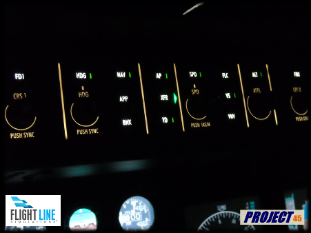
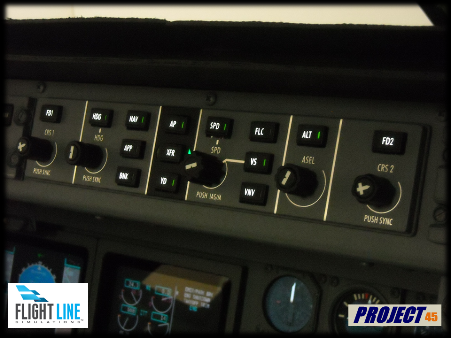
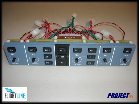
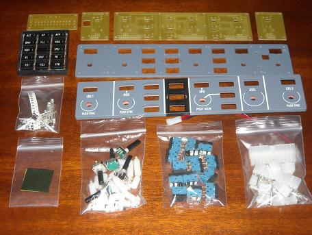
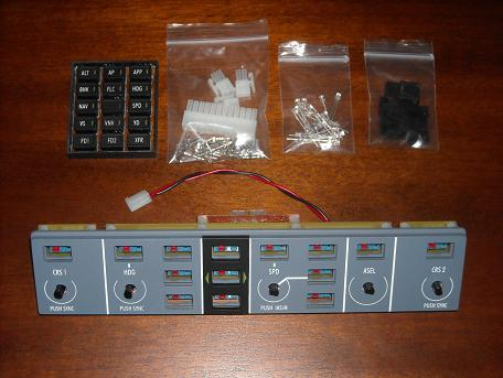
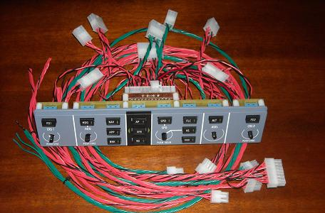
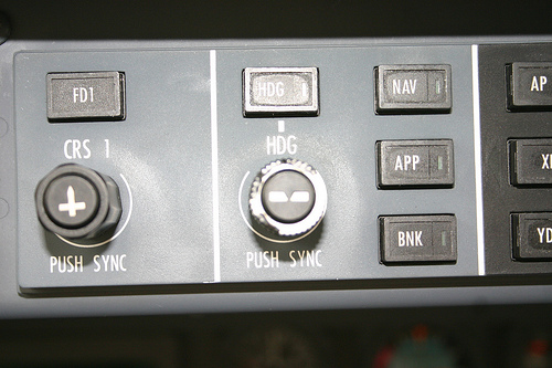
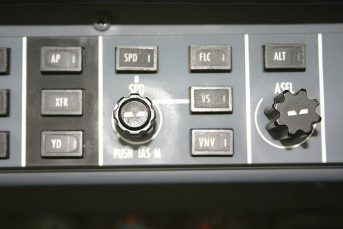
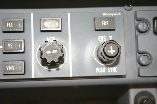
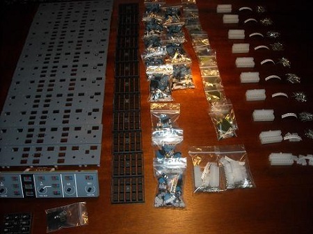
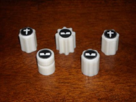
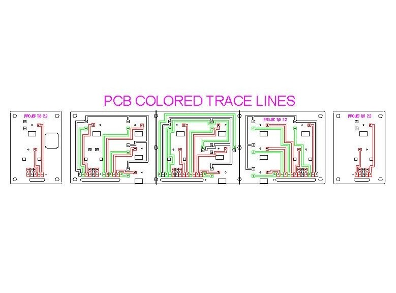
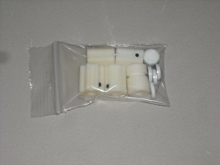
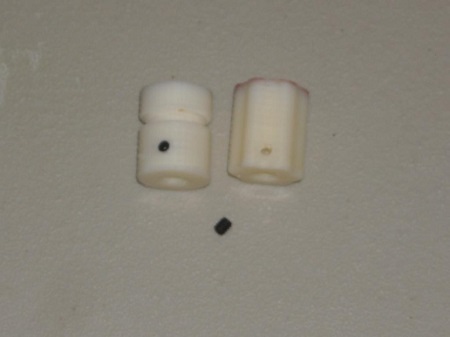
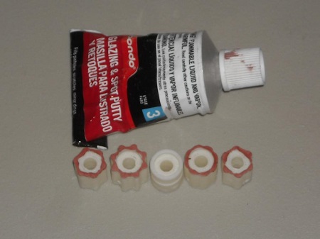
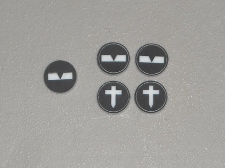

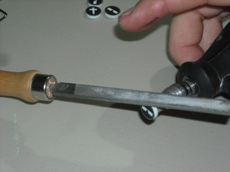
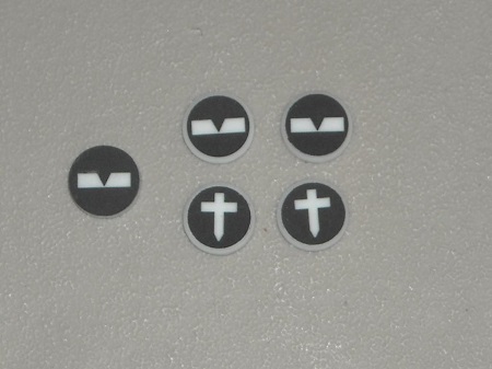
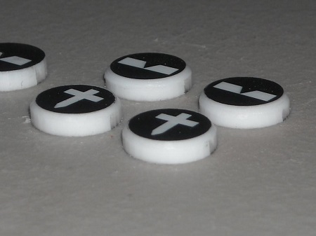
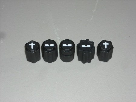
![]()
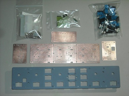
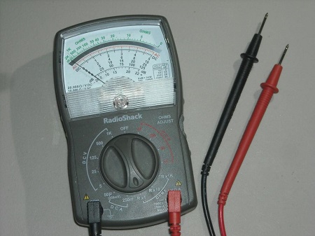
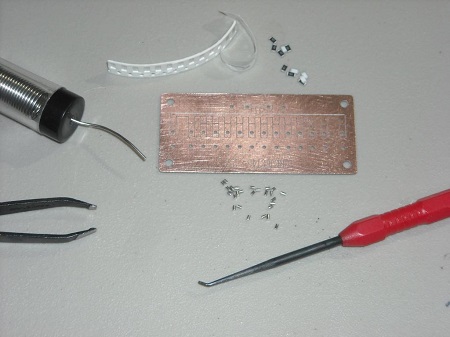
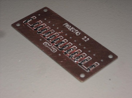
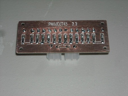
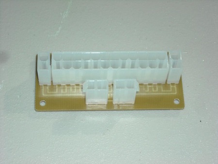
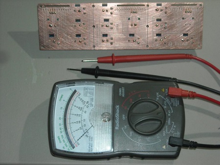
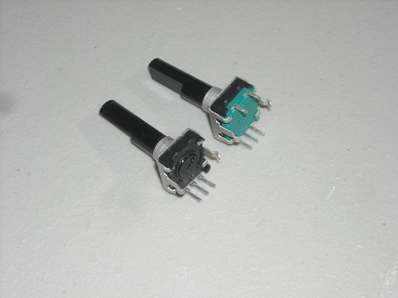
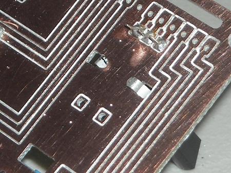
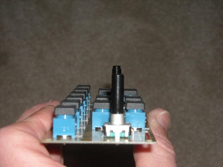
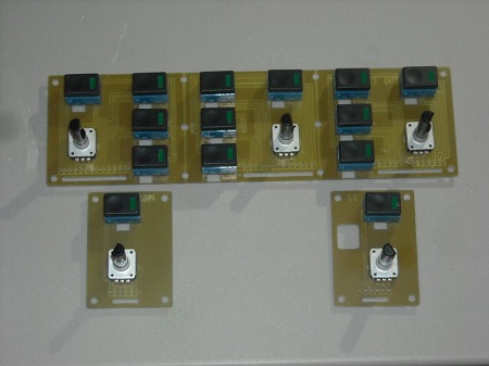
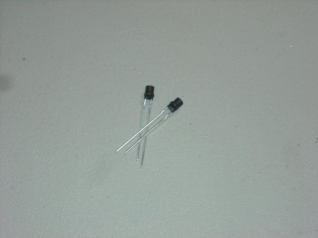
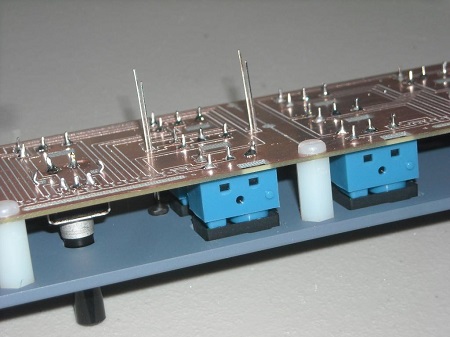
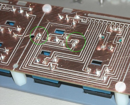
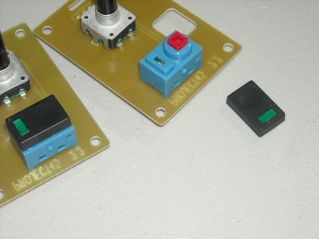
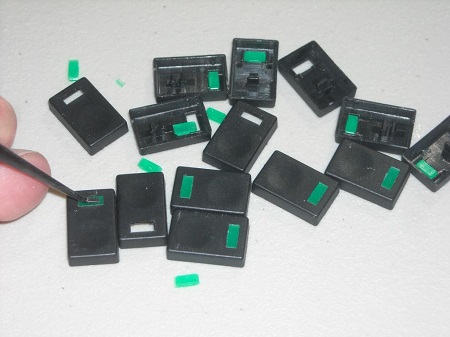
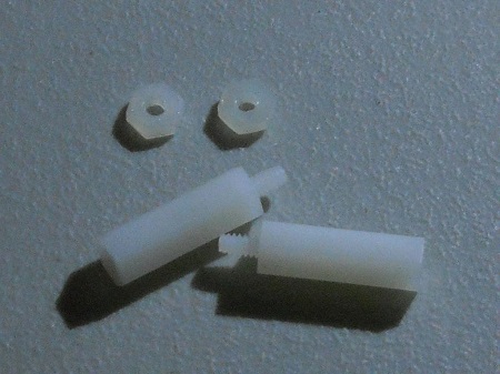
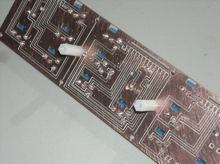
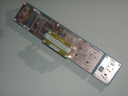
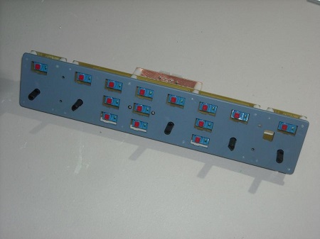
![]()

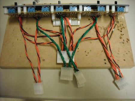
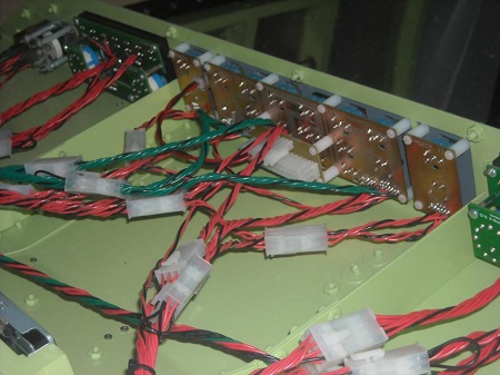
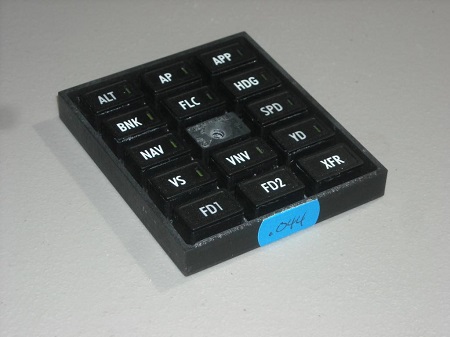
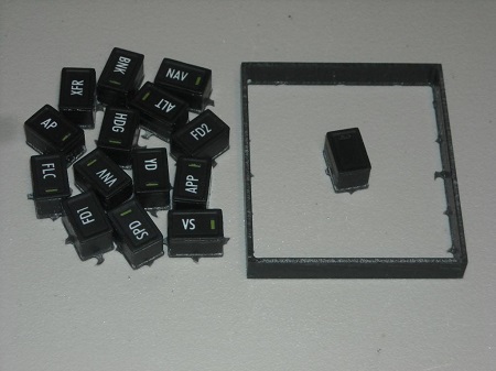
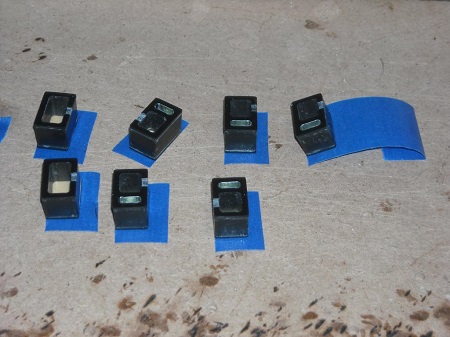
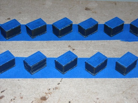
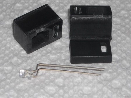
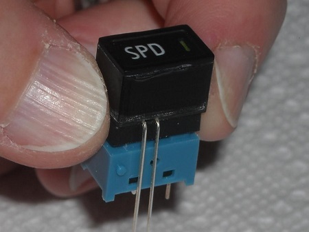
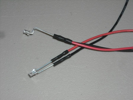
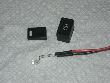
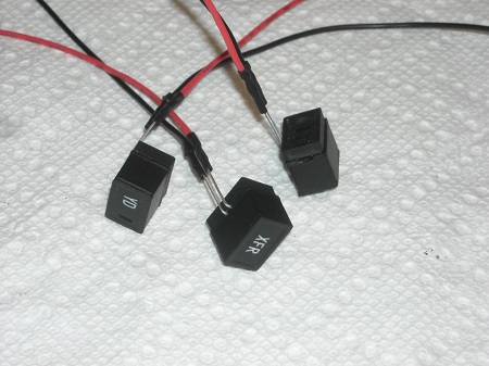
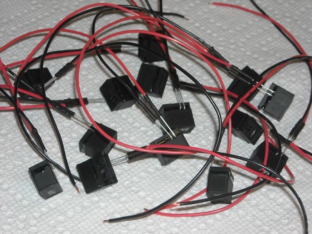
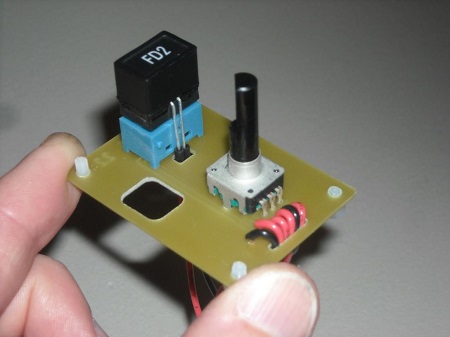
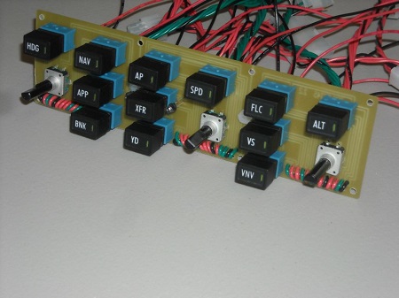
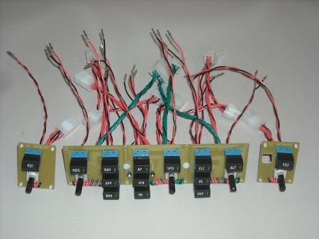
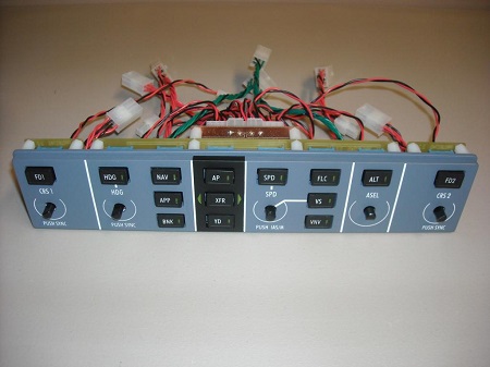


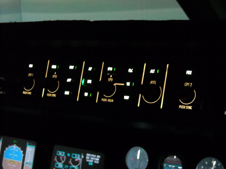
![]()
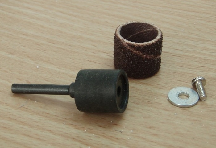
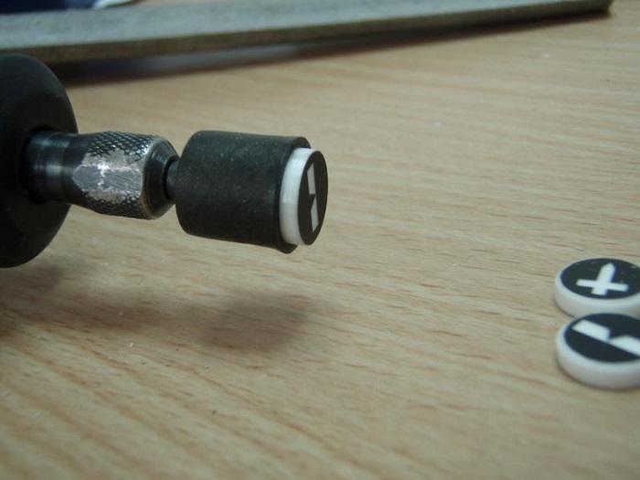
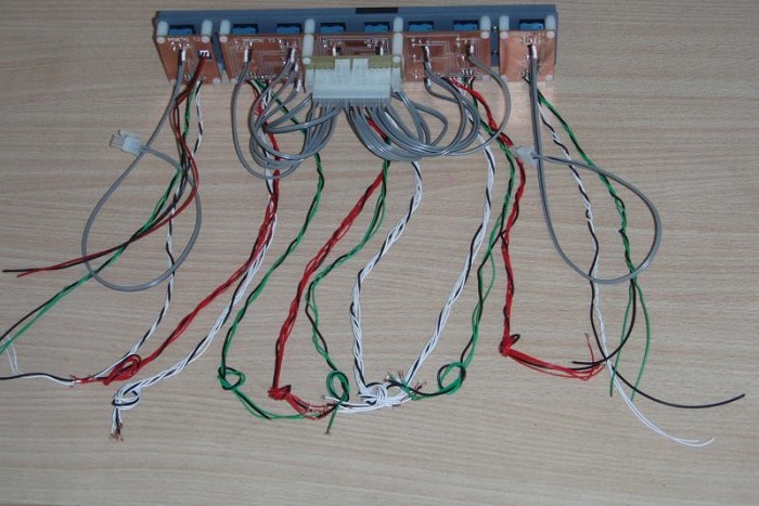
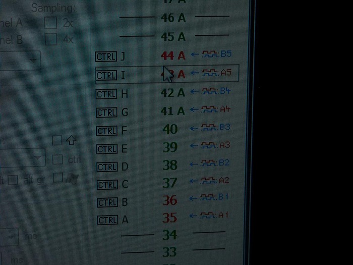
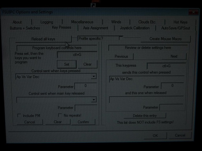
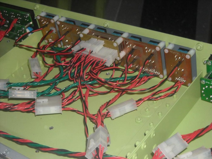

![]()
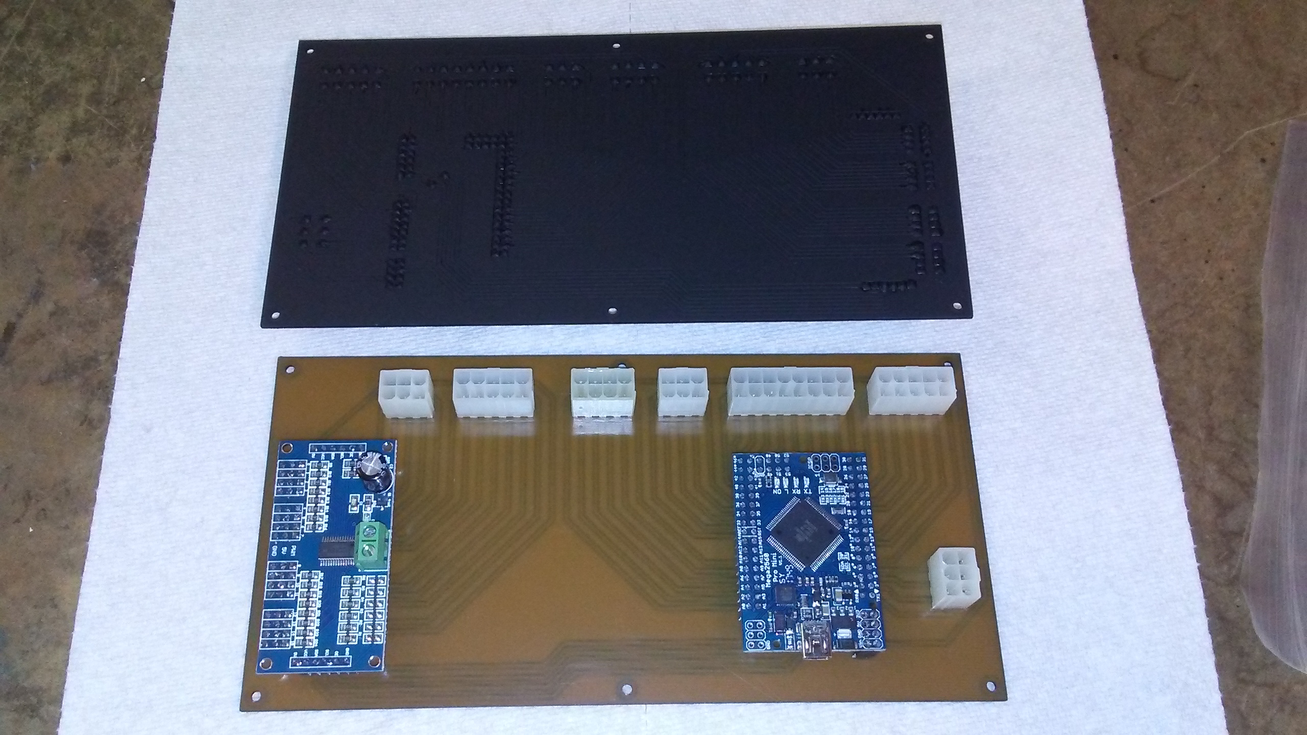
![]()
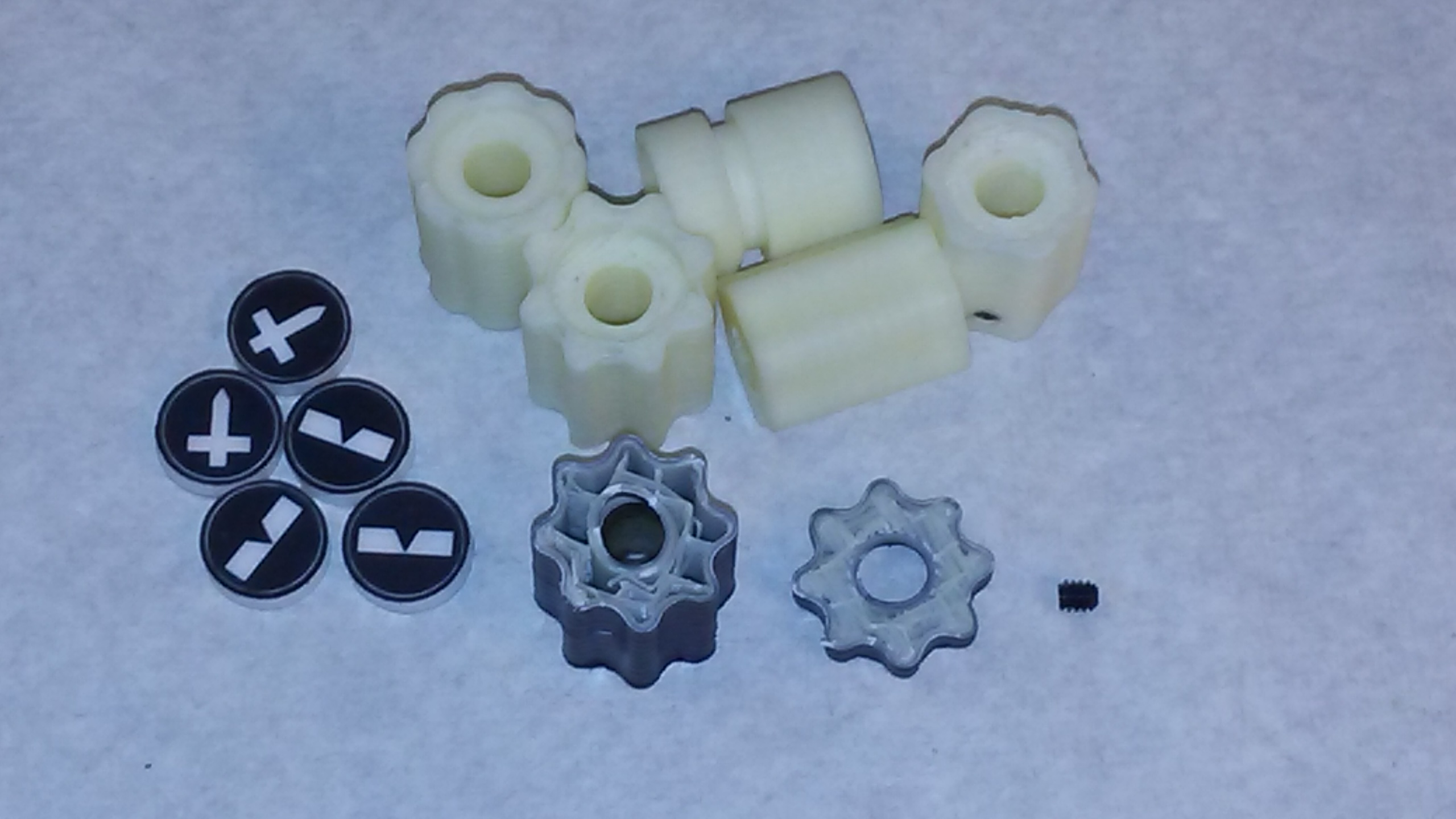
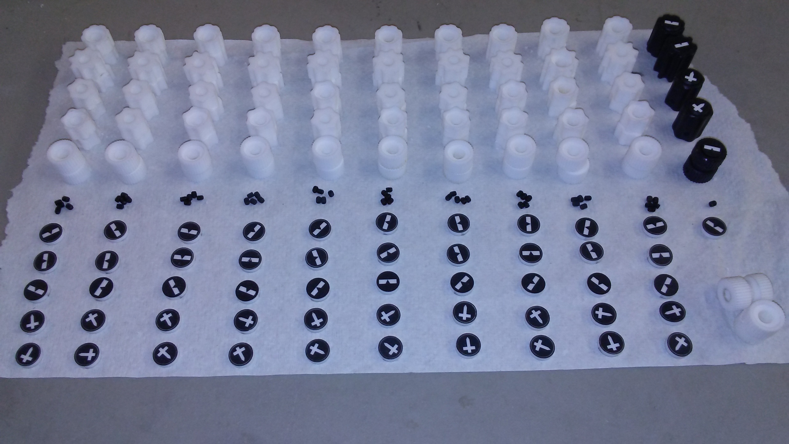
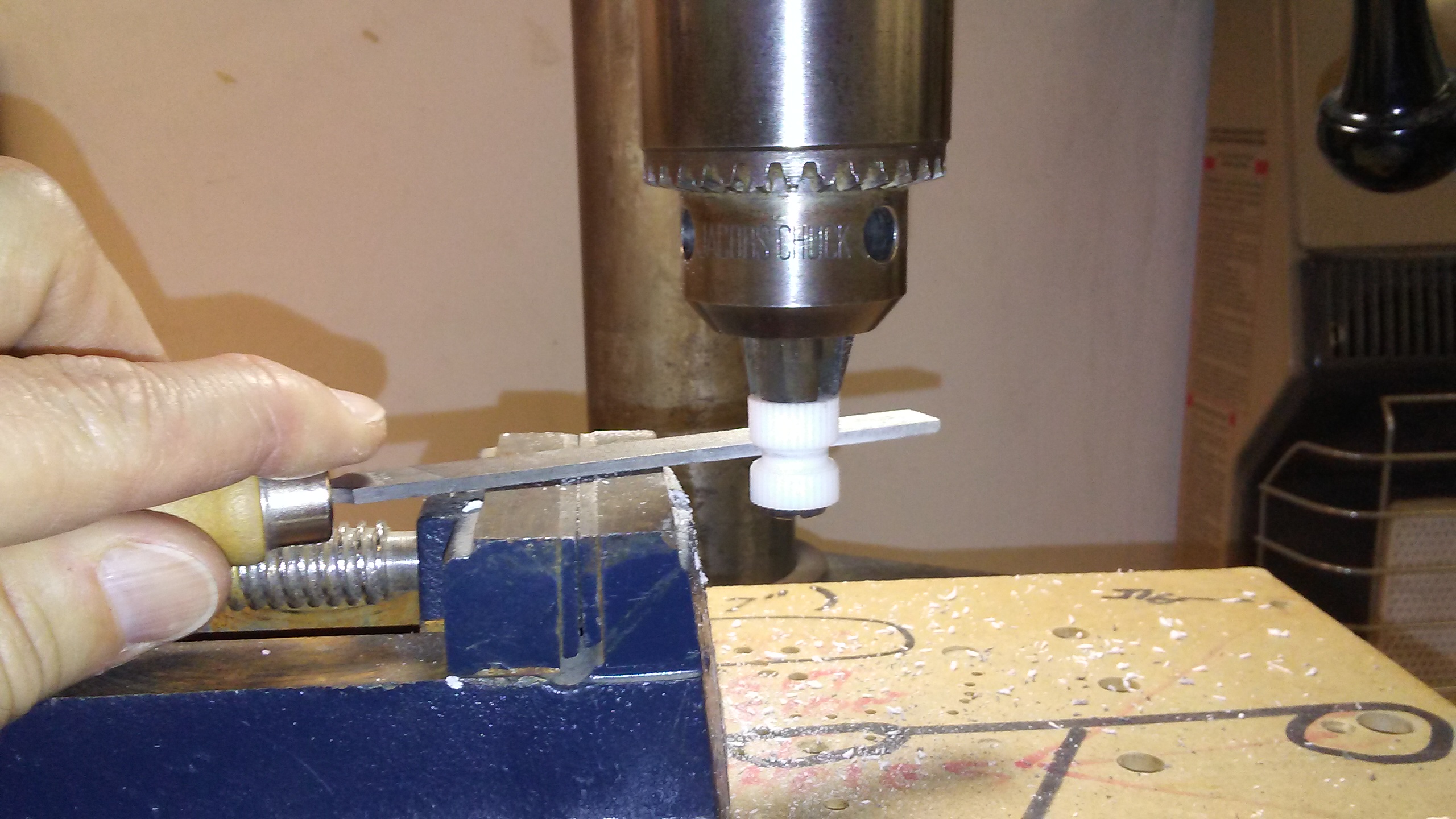
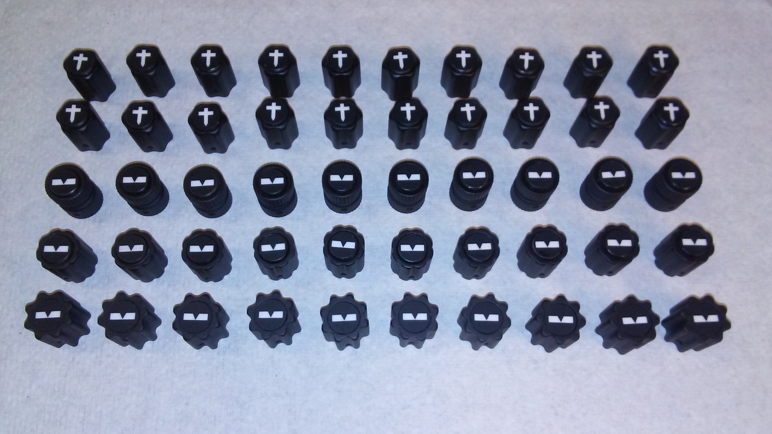
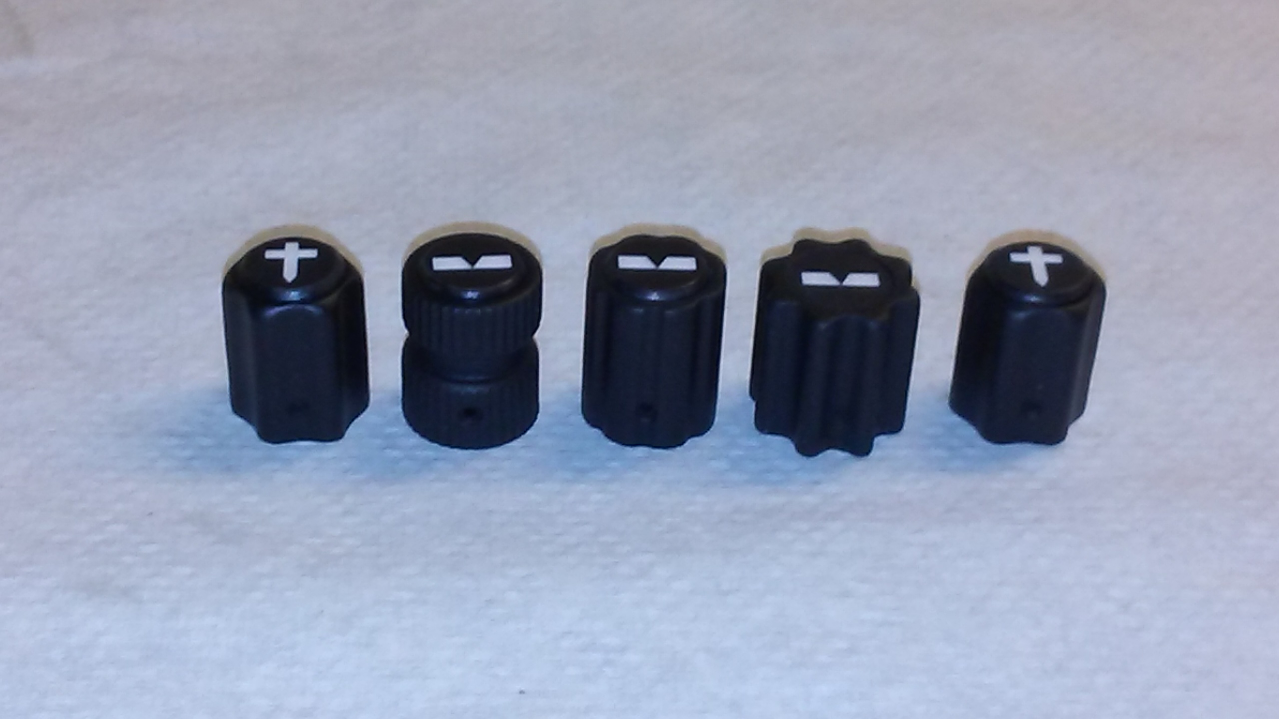
![]()
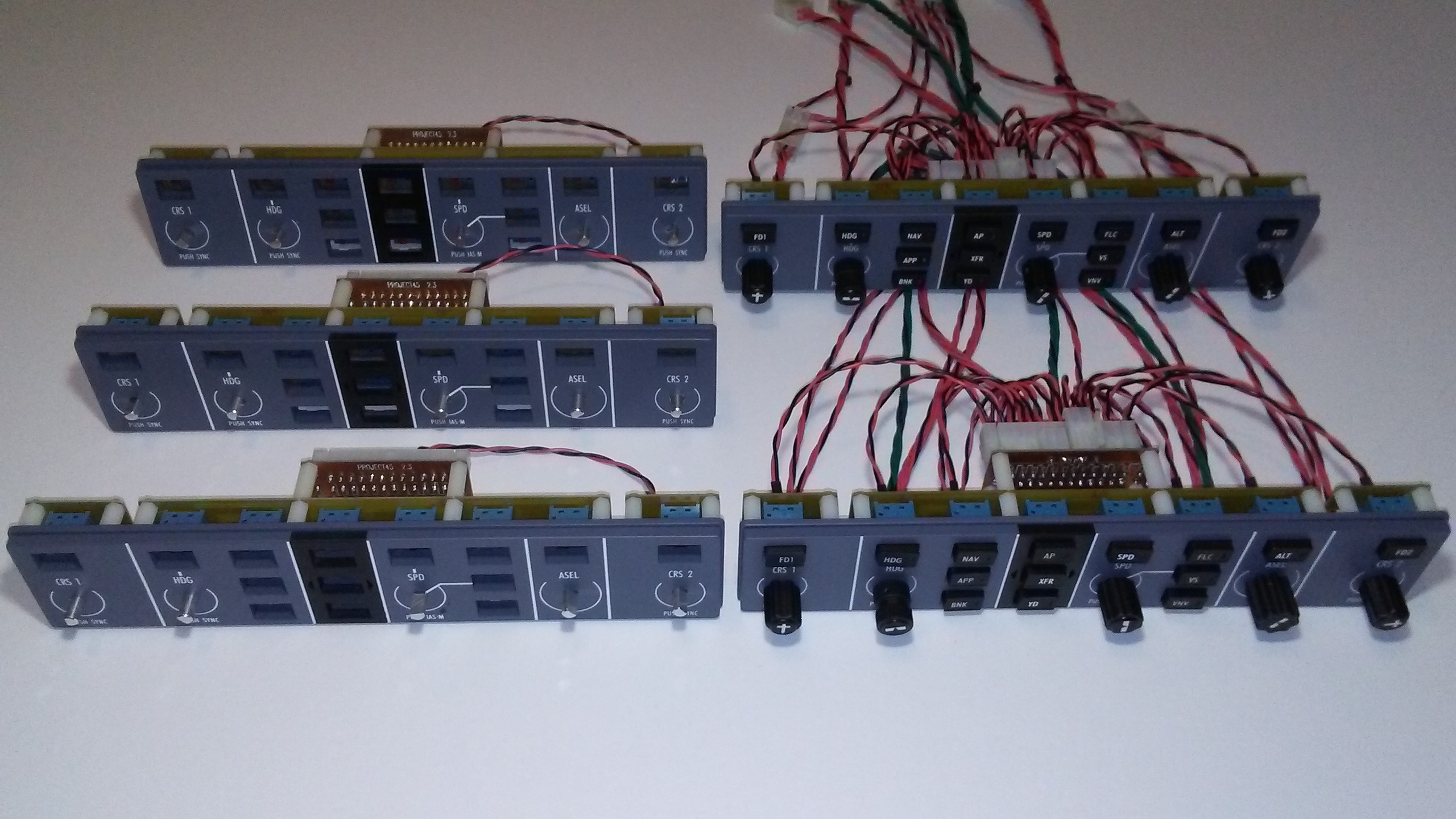
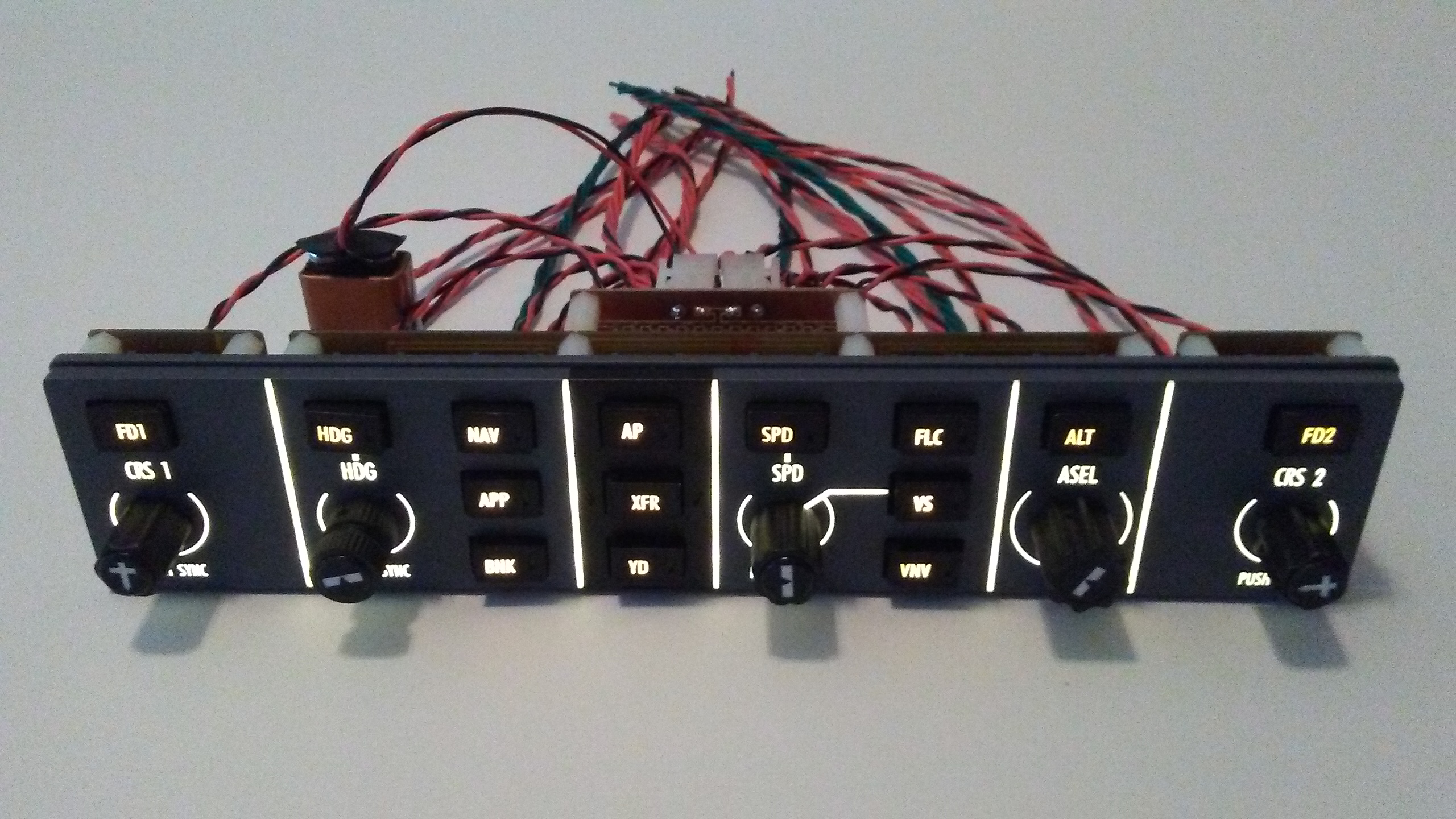
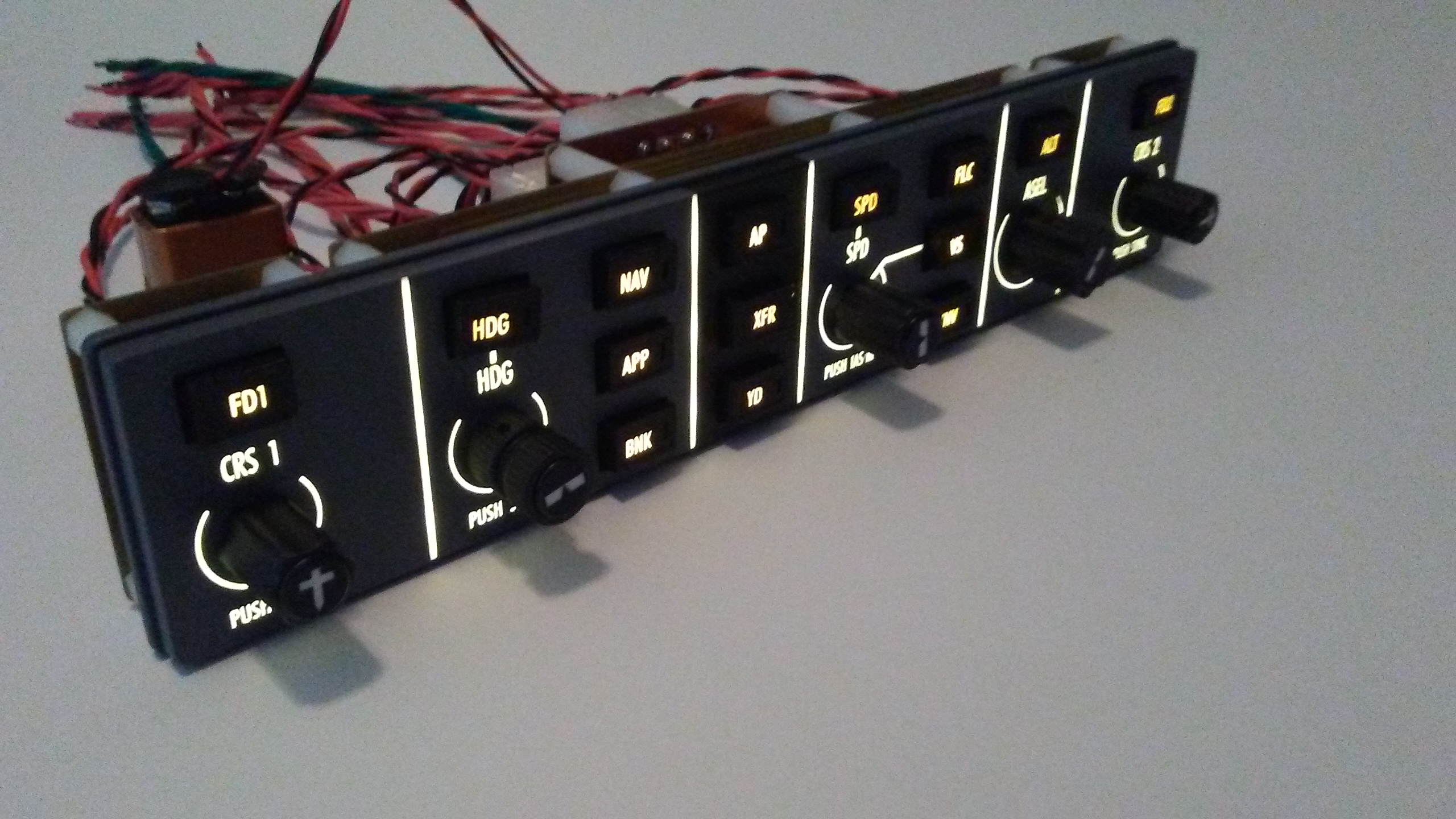
![]()
If so, are they transparent material (would be better for transferring the green led light) , or are they green transparent material?
If so, are they transparent material (would be better for transferring the green led light) , or are they green transparent material?![]()
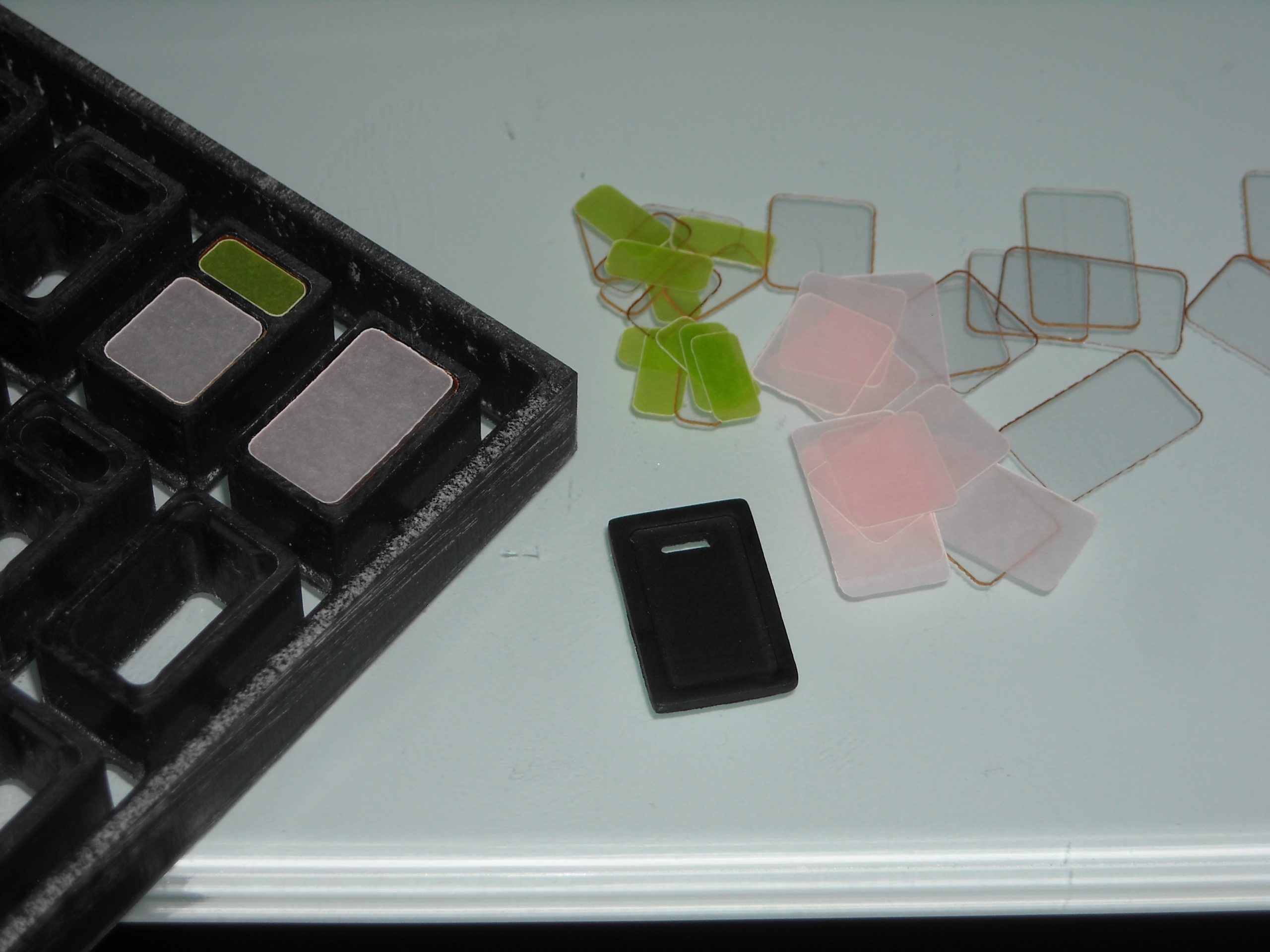
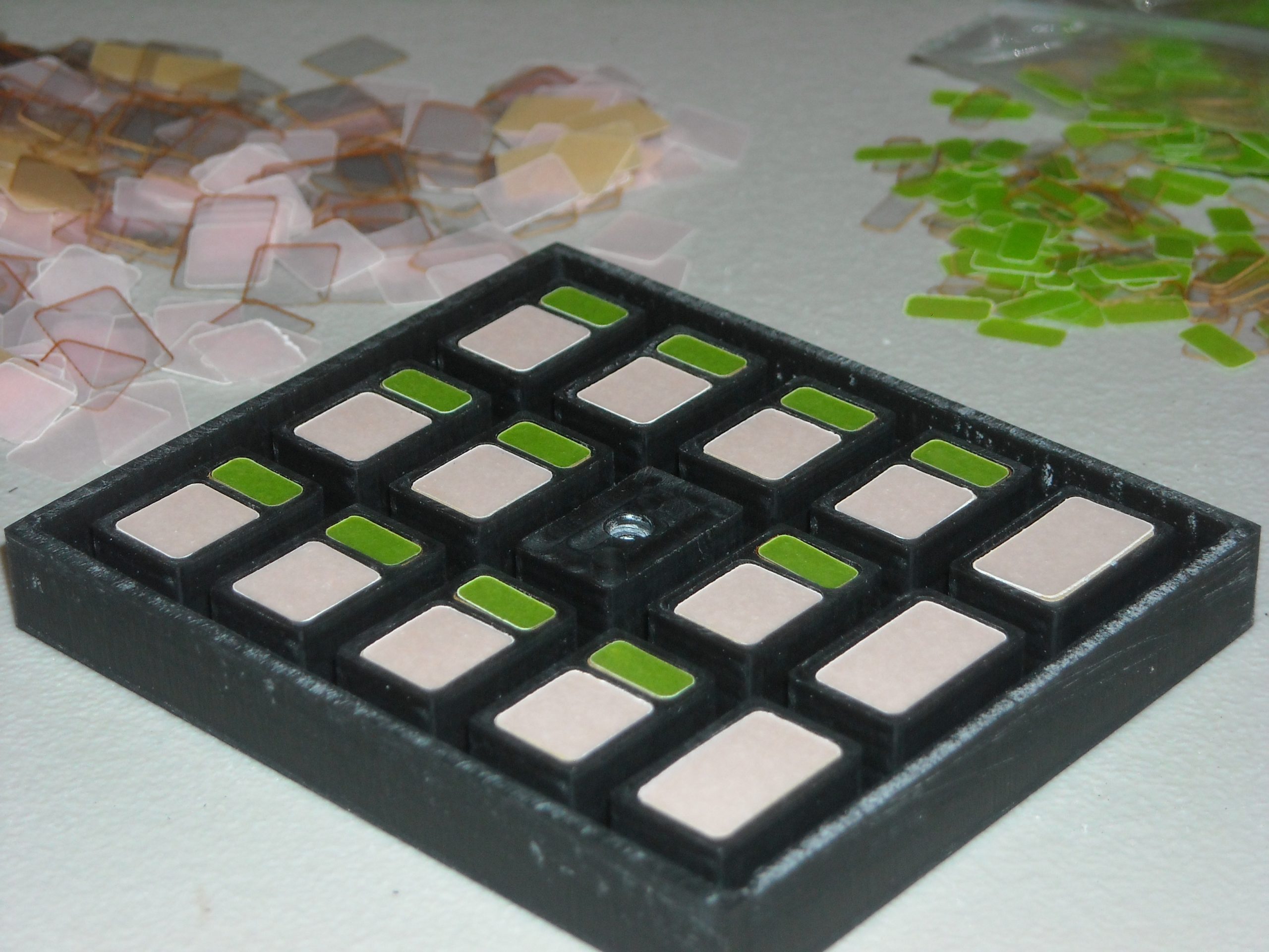
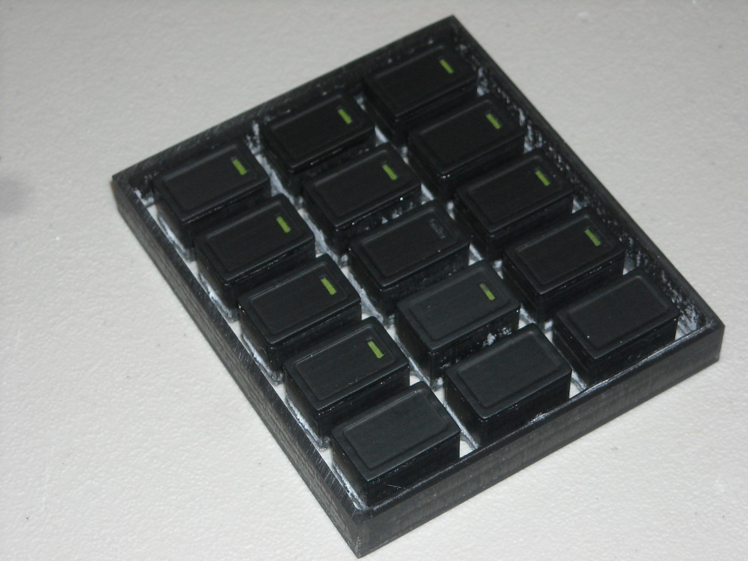
![]()
Open Cockpits also used them in their B737 MCP.
Milling works fine , i am still not happy with my laser cutting: material gets too burned or melted.
With a selfmade cap this could work maybe.
Open Cockpits also used them in their B737 MCP.
Milling works fine , i am still not happy with my laser cutting: material gets too burned or melted.
With a selfmade cap this could work maybe.
Forum NavigationFlight Guidance Controller Discussion
![]() #1 · December 14, 2017, 8:26 am
#1 · December 14, 2017, 8:26 am![]() #2 · January 5, 2018, 3:39 pm
#2 · January 5, 2018, 3:39 pm![]() #3 · January 8, 2018, 6:59 am
#3 · January 8, 2018, 6:59 am![]() #4 · January 8, 2018, 7:51 am
#4 · January 8, 2018, 7:51 am![]() #5 · September 14, 2018, 10:18 pm
#5 · September 14, 2018, 10:18 pm![]() #6 · September 25, 2018, 9:24 pm
#6 · September 25, 2018, 9:24 pm![]() #7 · July 30, 2019, 10:49 am
#7 · July 30, 2019, 10:49 am![]() #8 · April 30, 2020, 6:08 am
#8 · April 30, 2020, 6:08 am![]() #9 · April 30, 2020, 7:03 am
#9 · April 30, 2020, 7:03 am![]() #10 · April 30, 2020, 7:46 am
#10 · April 30, 2020, 7:46 am
2017-10-10