


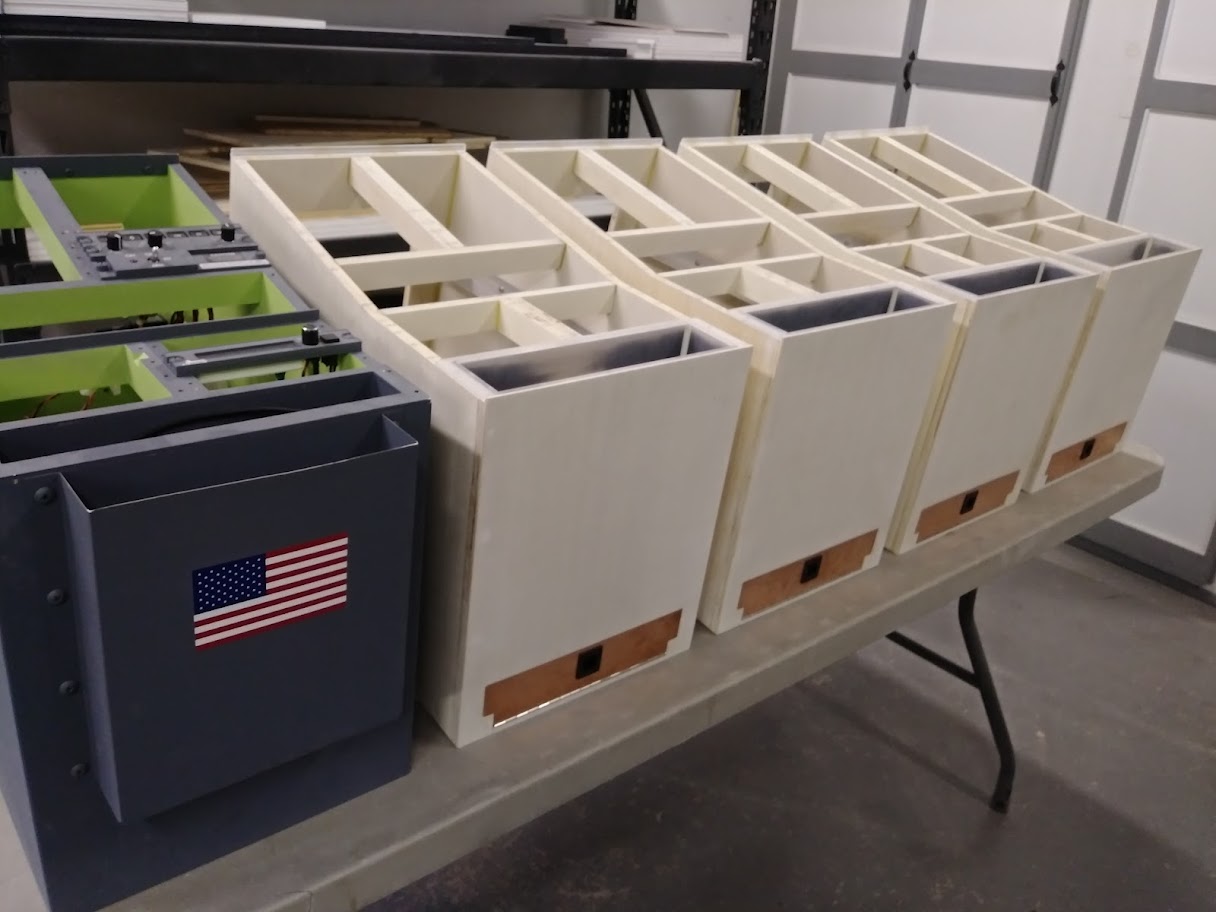
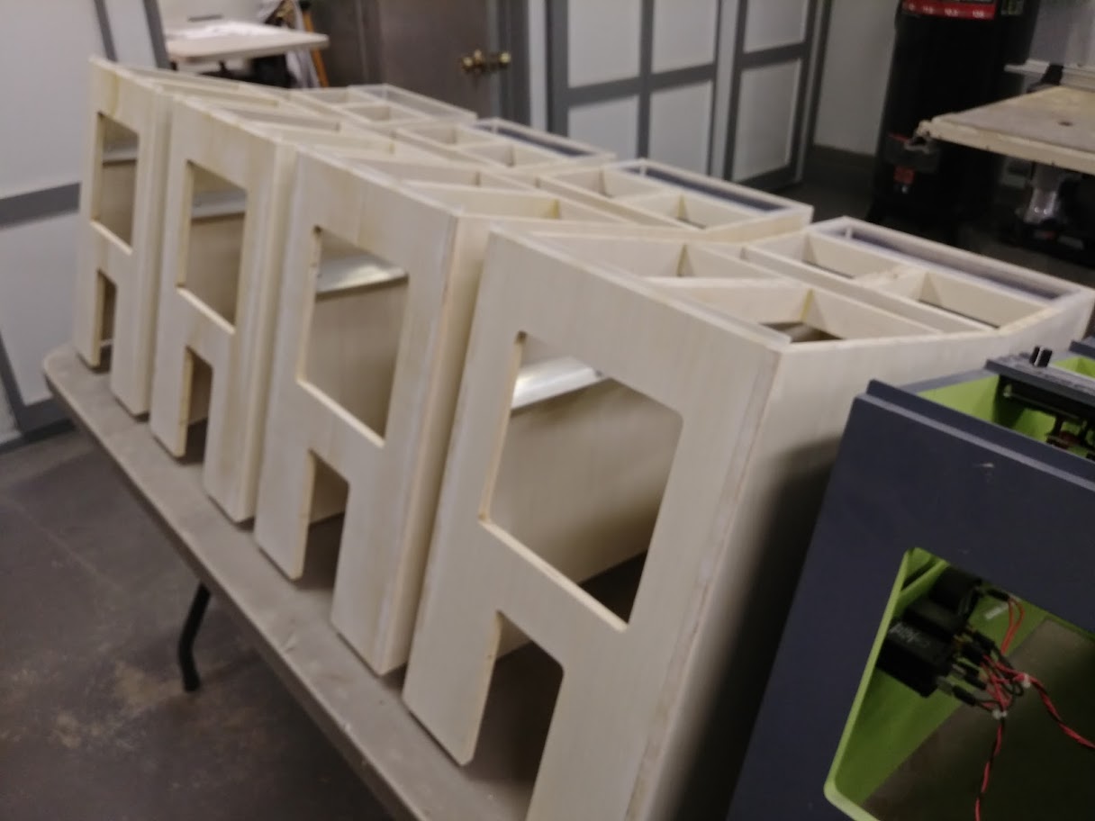
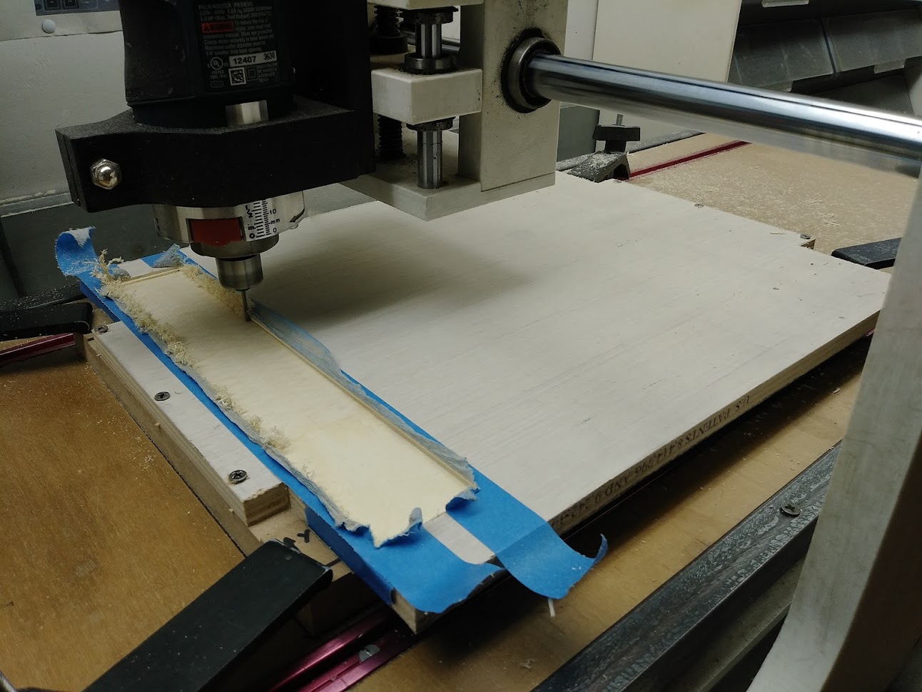
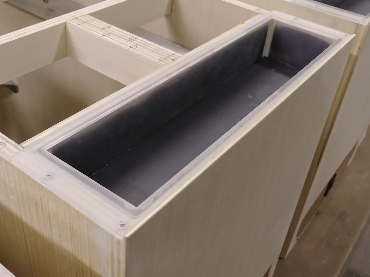
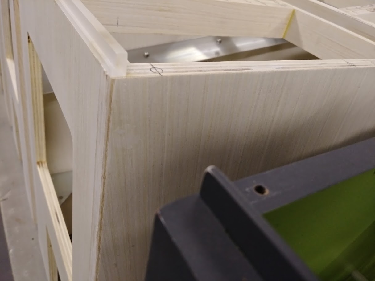
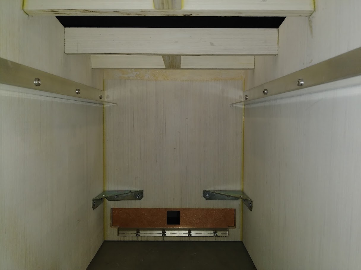
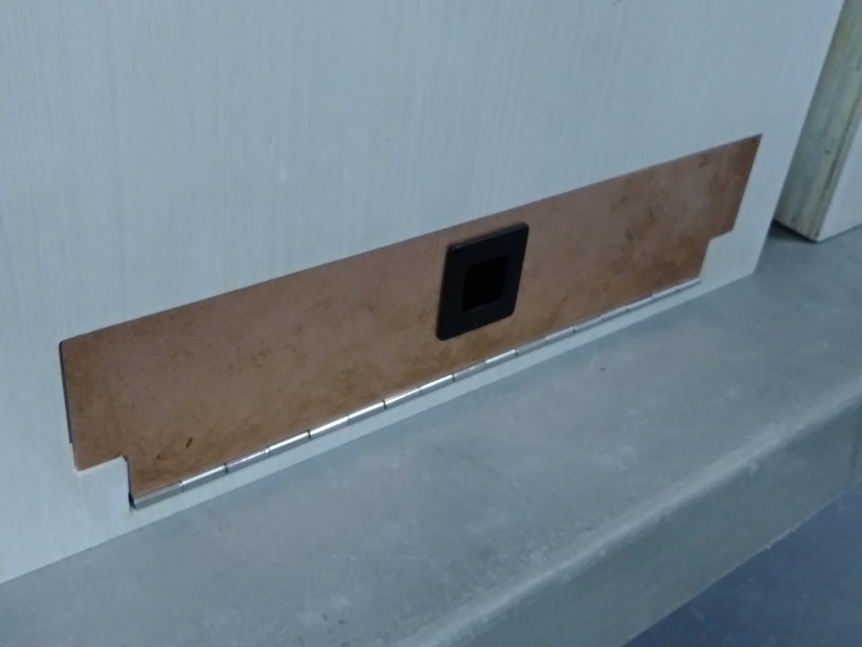
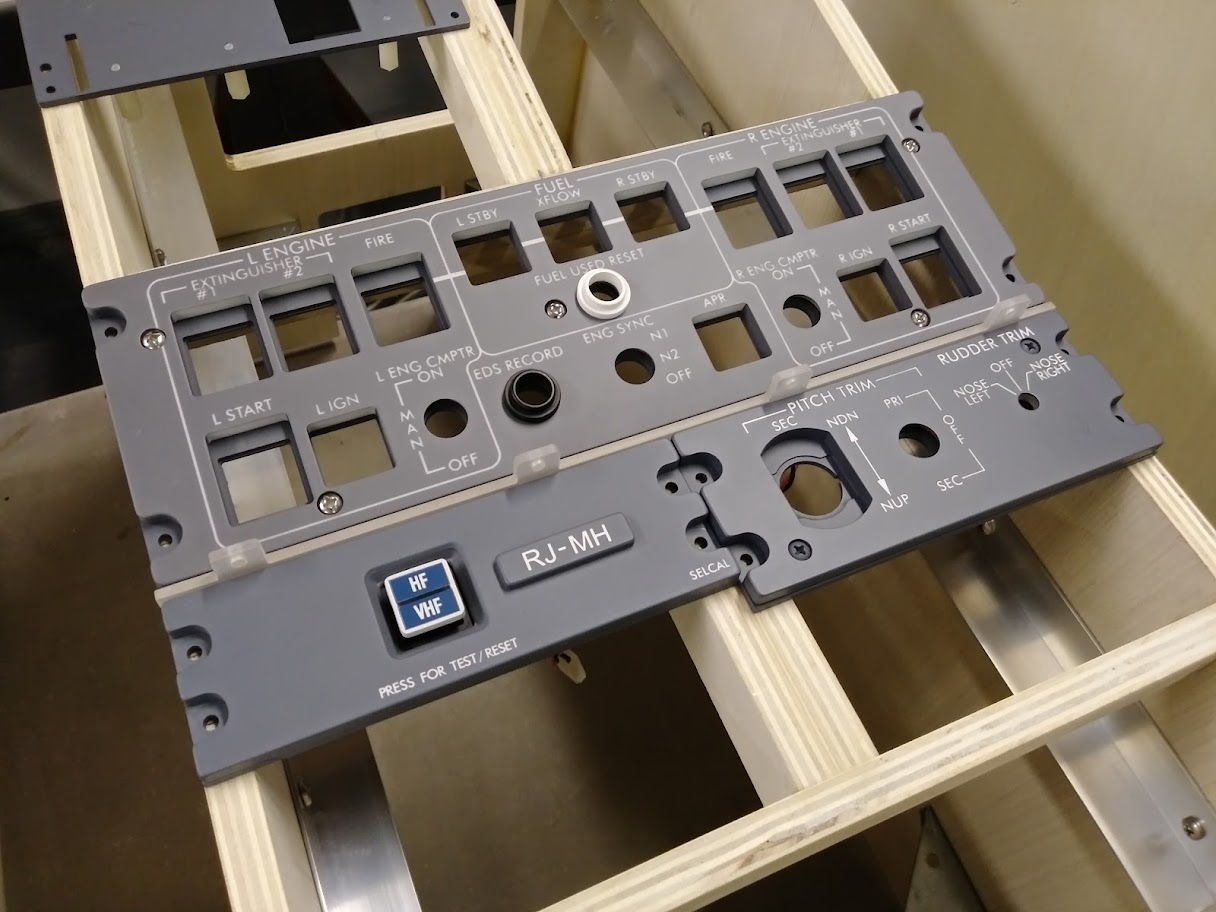
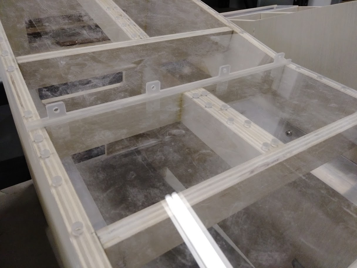
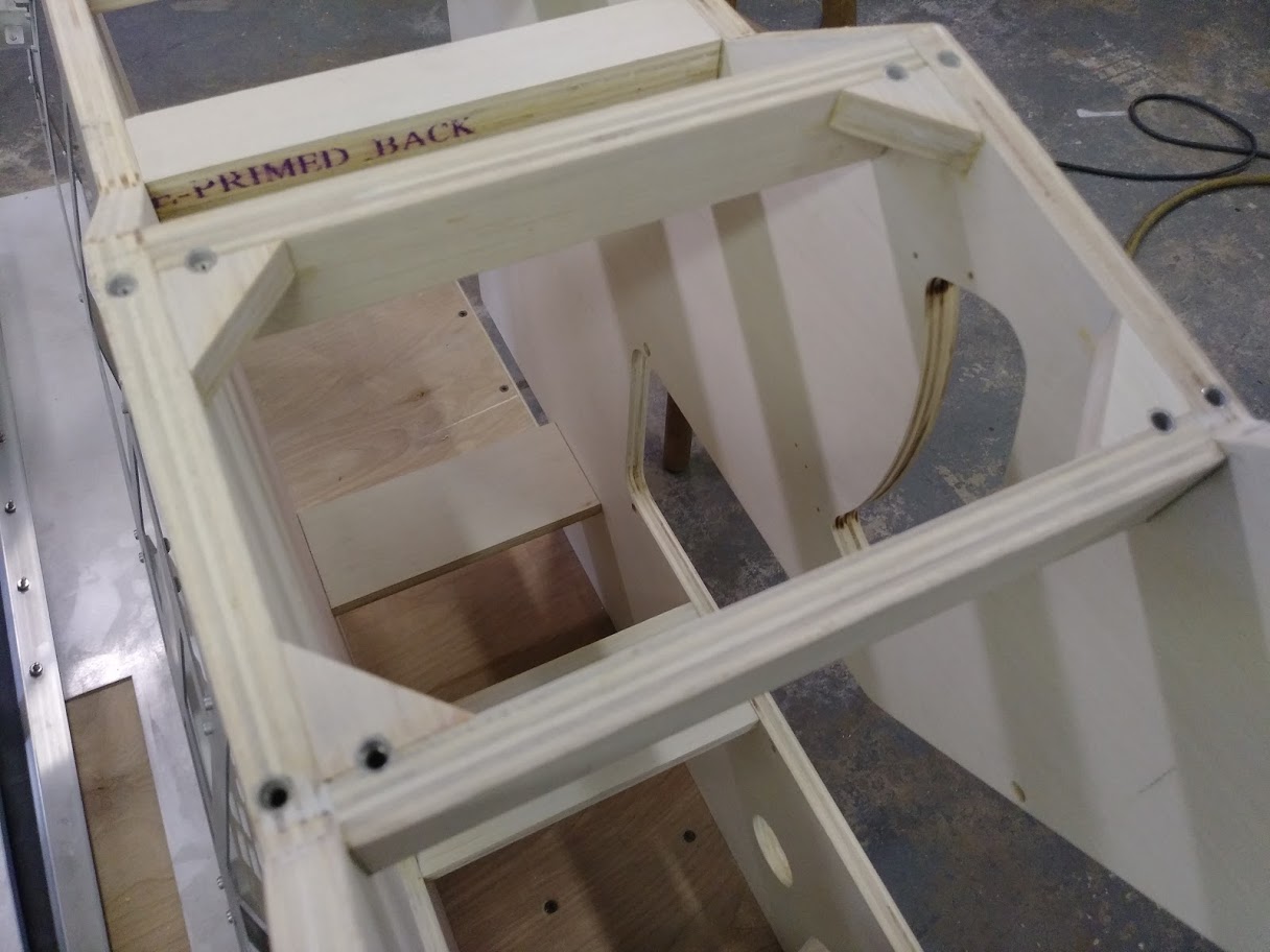
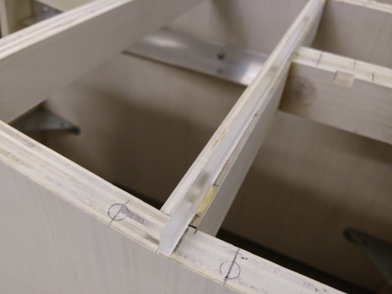
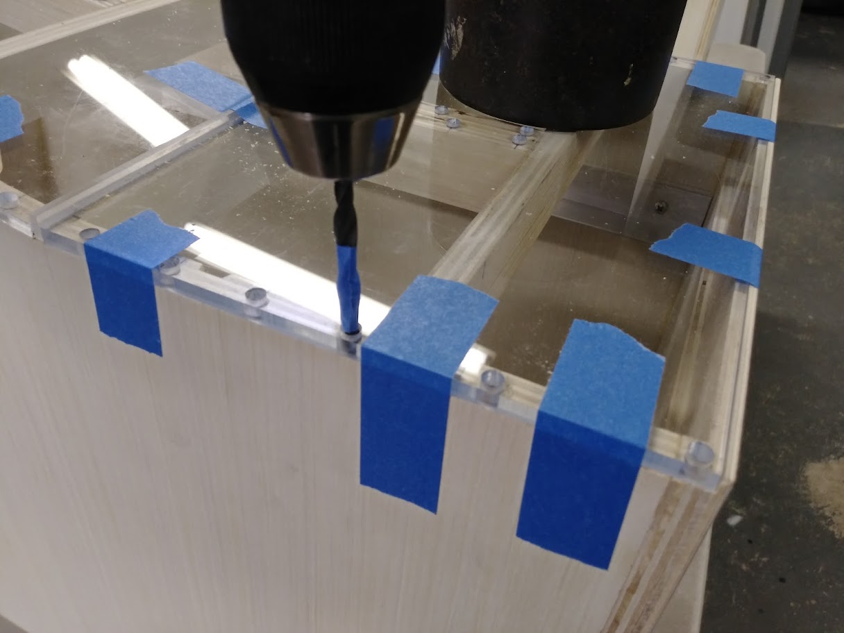
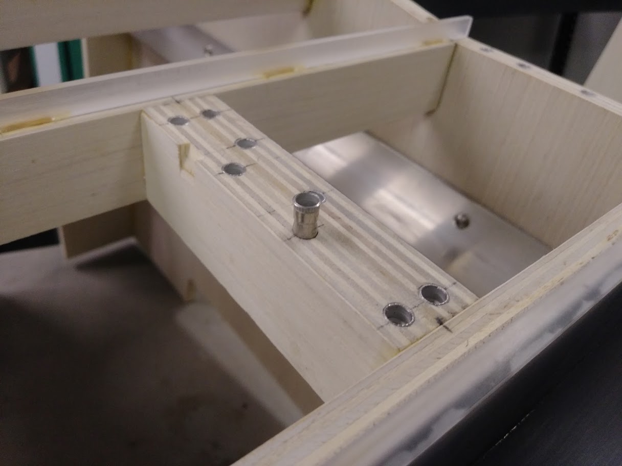
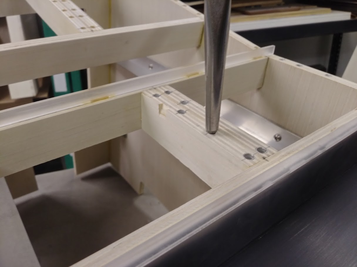
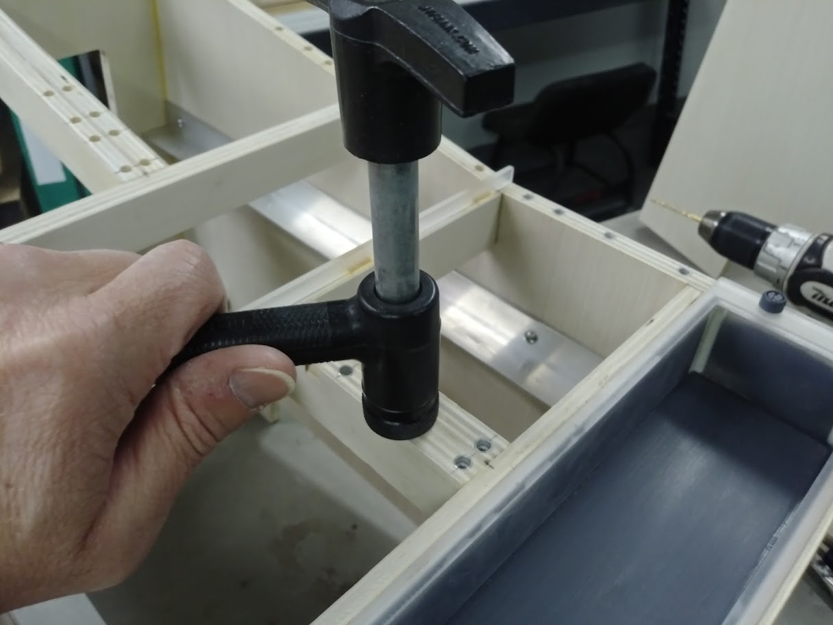
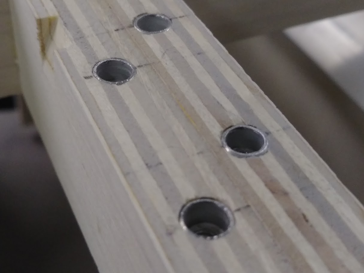
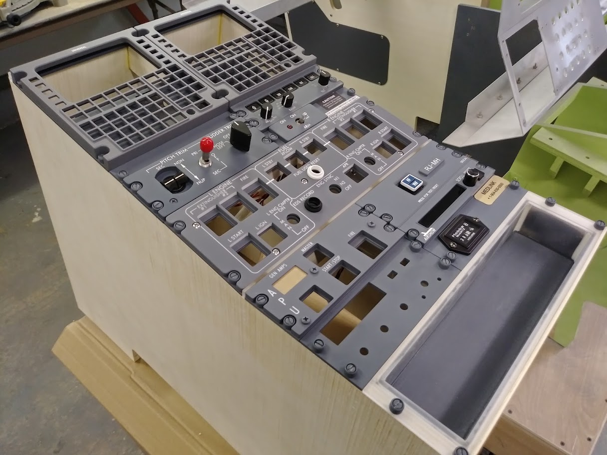
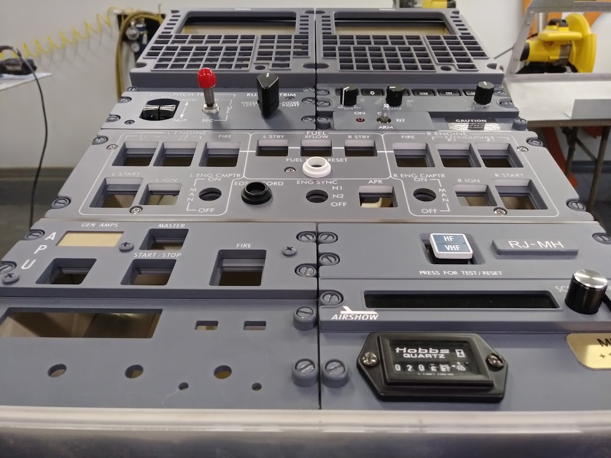
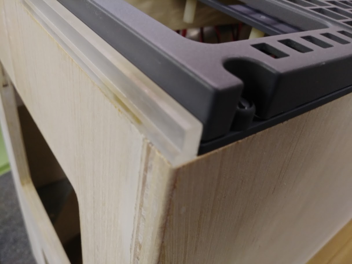
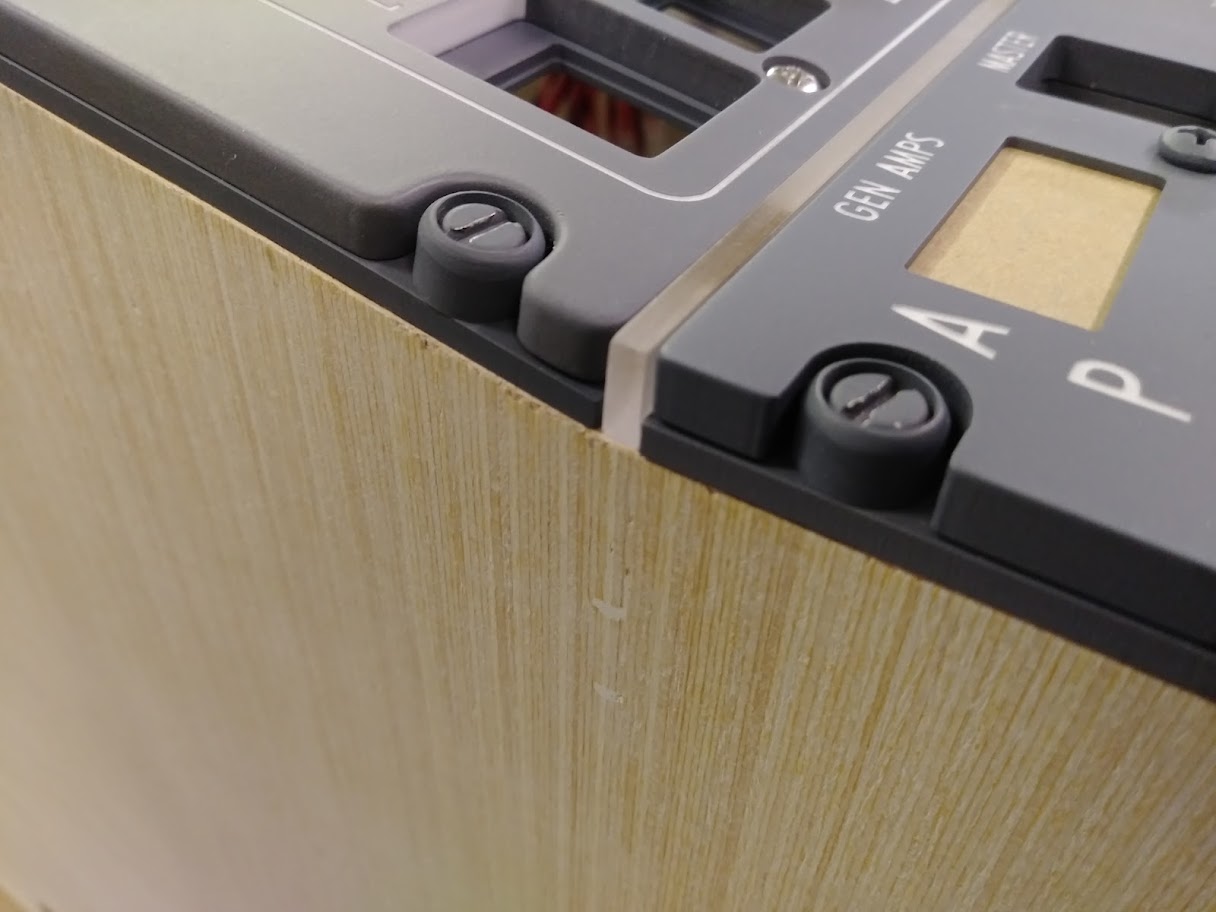
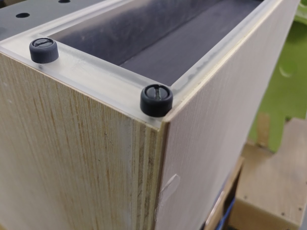
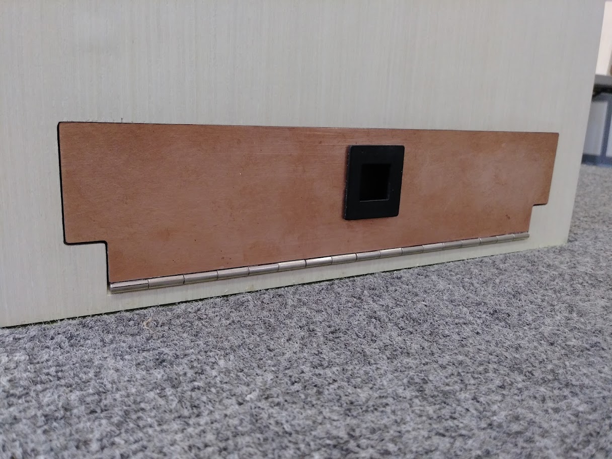
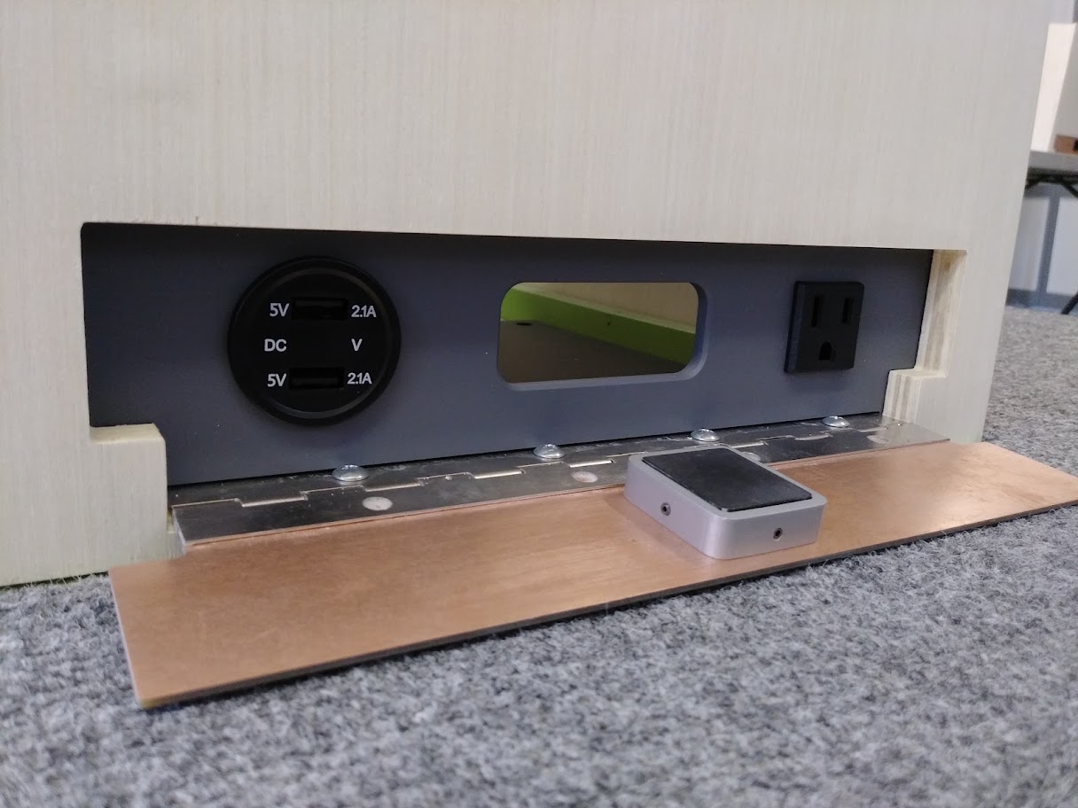
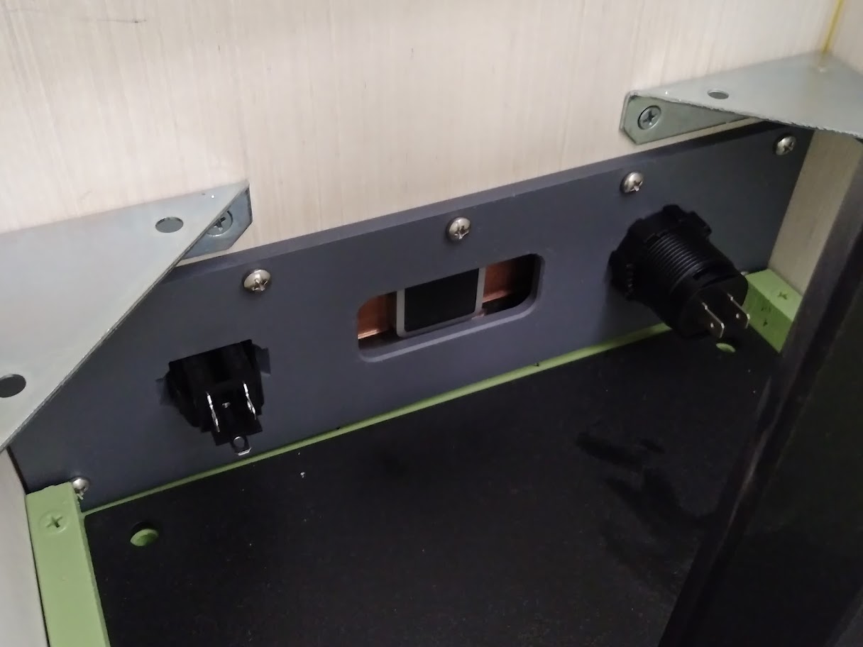
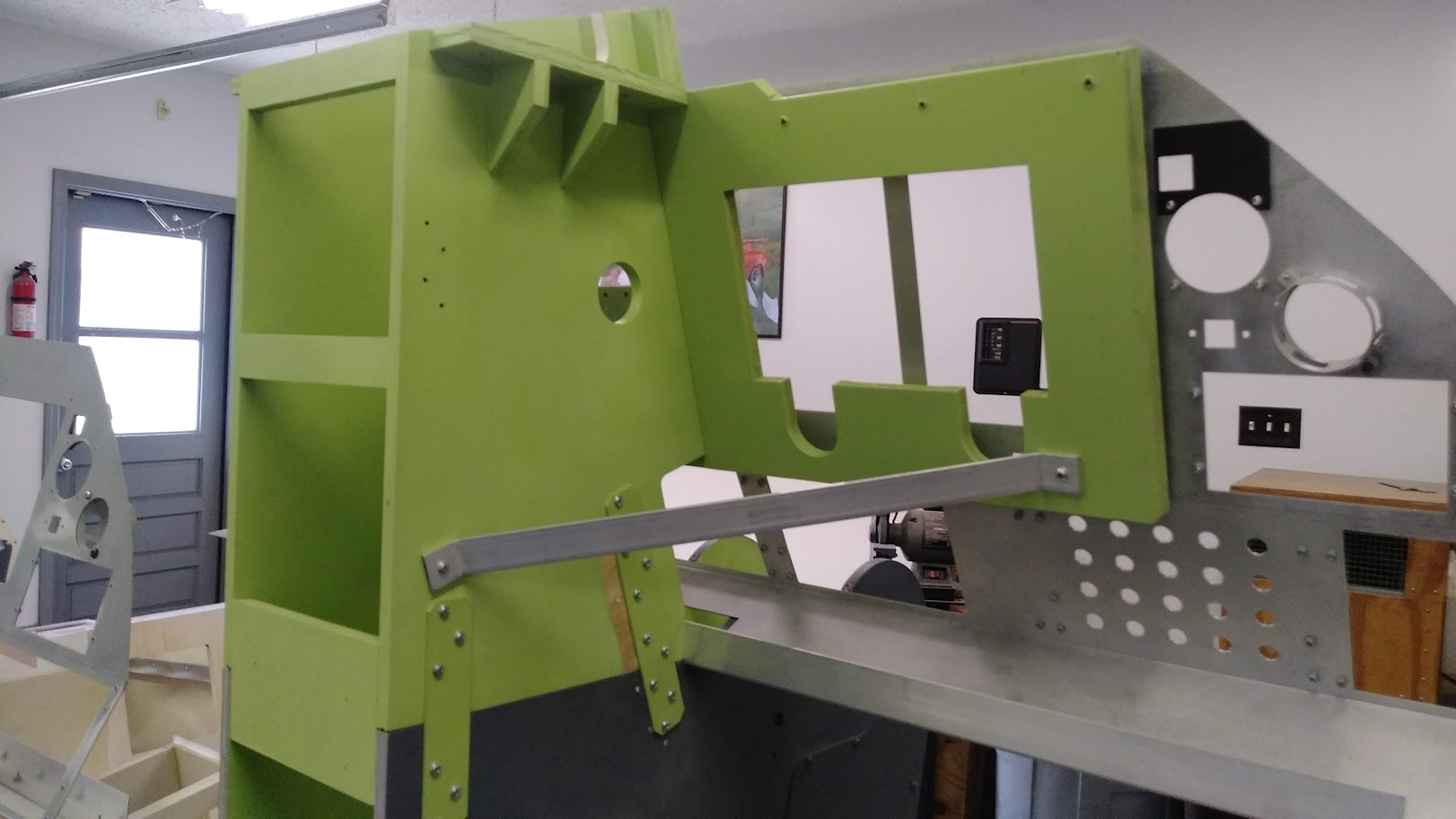
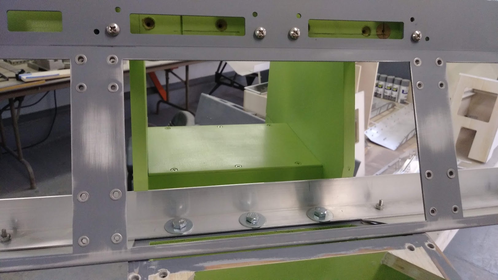
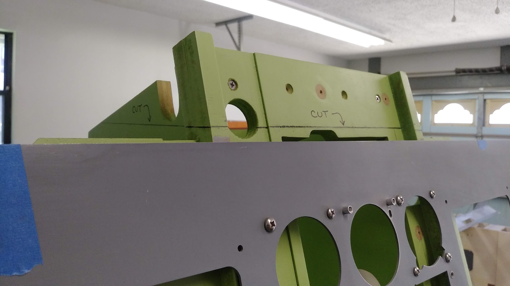
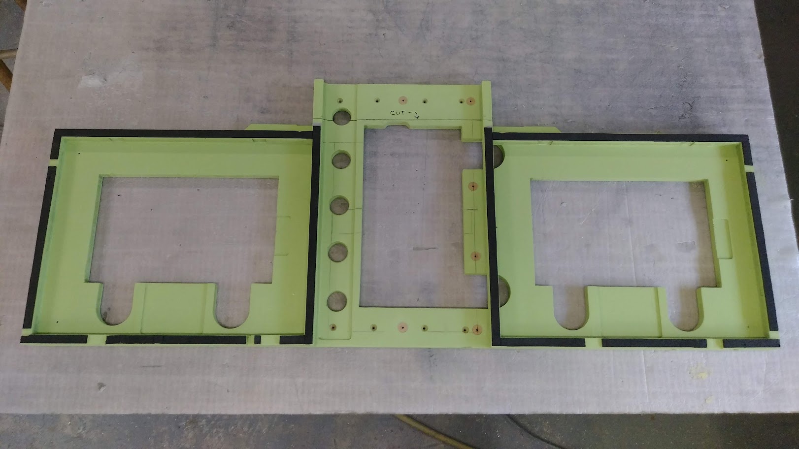
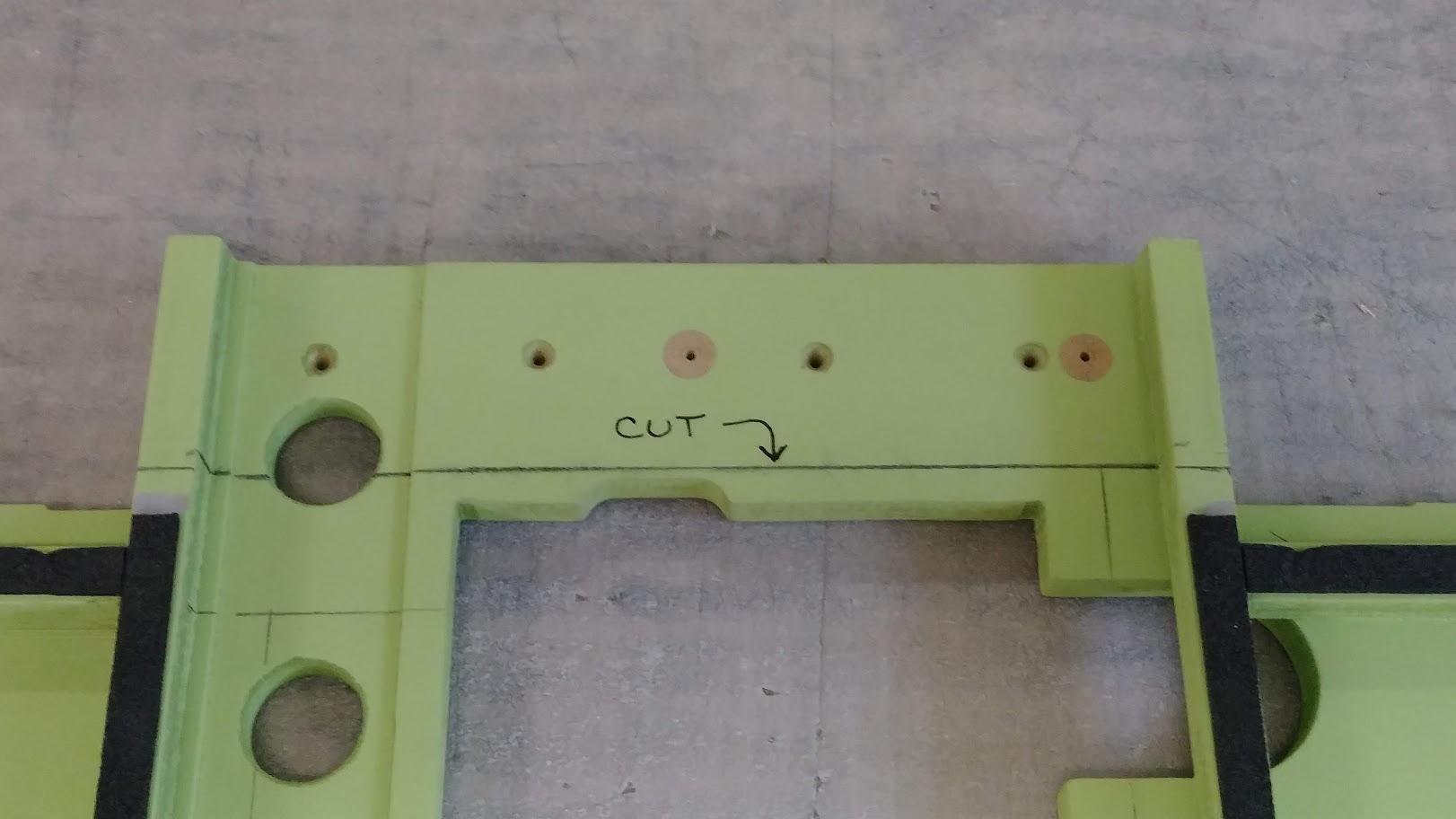
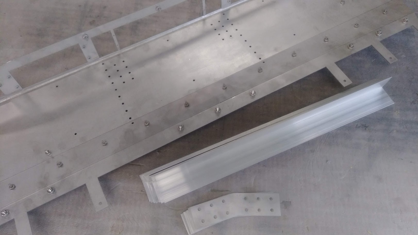
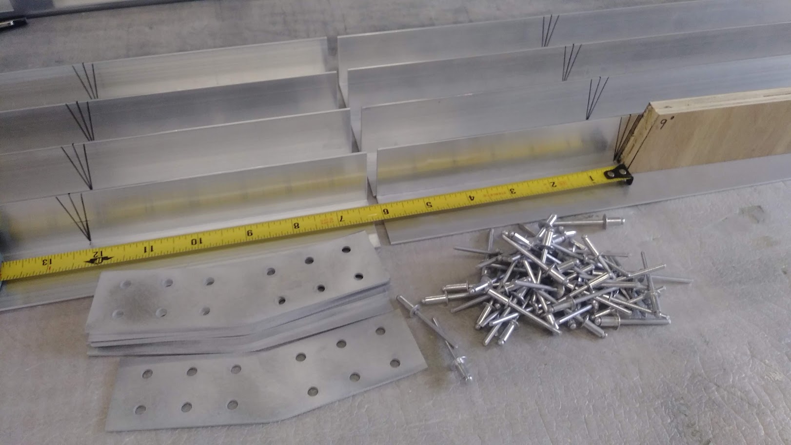
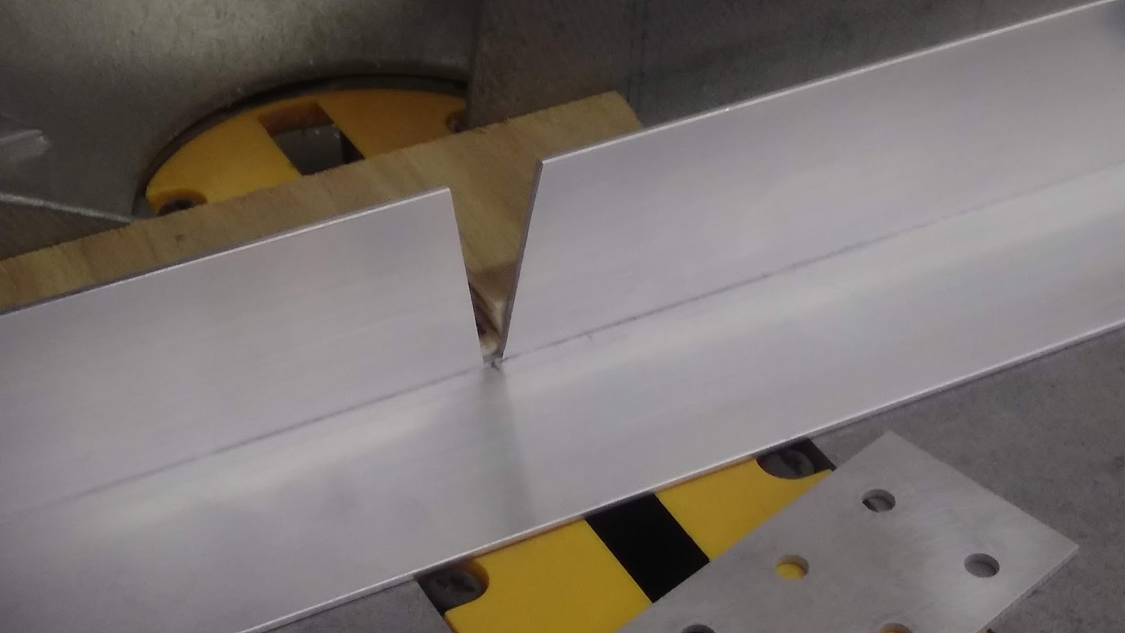
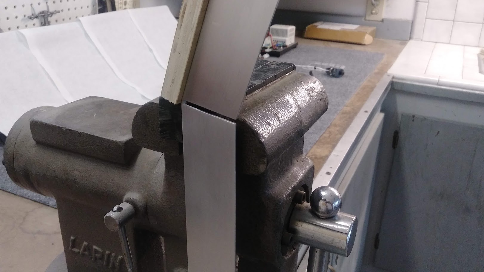
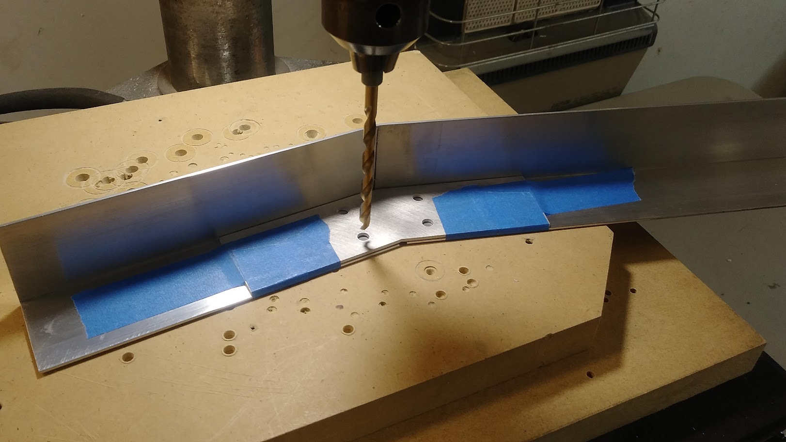
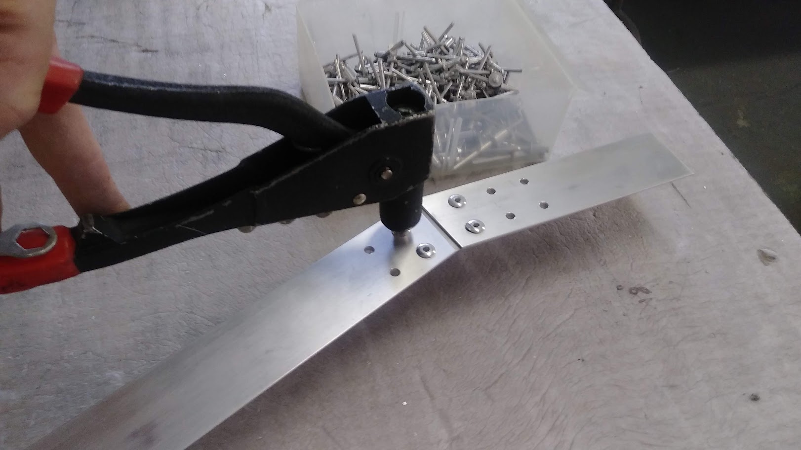
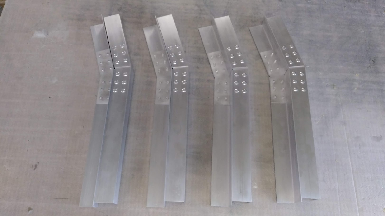
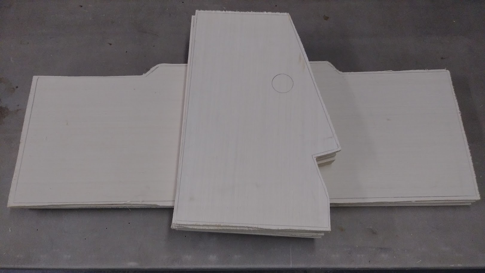
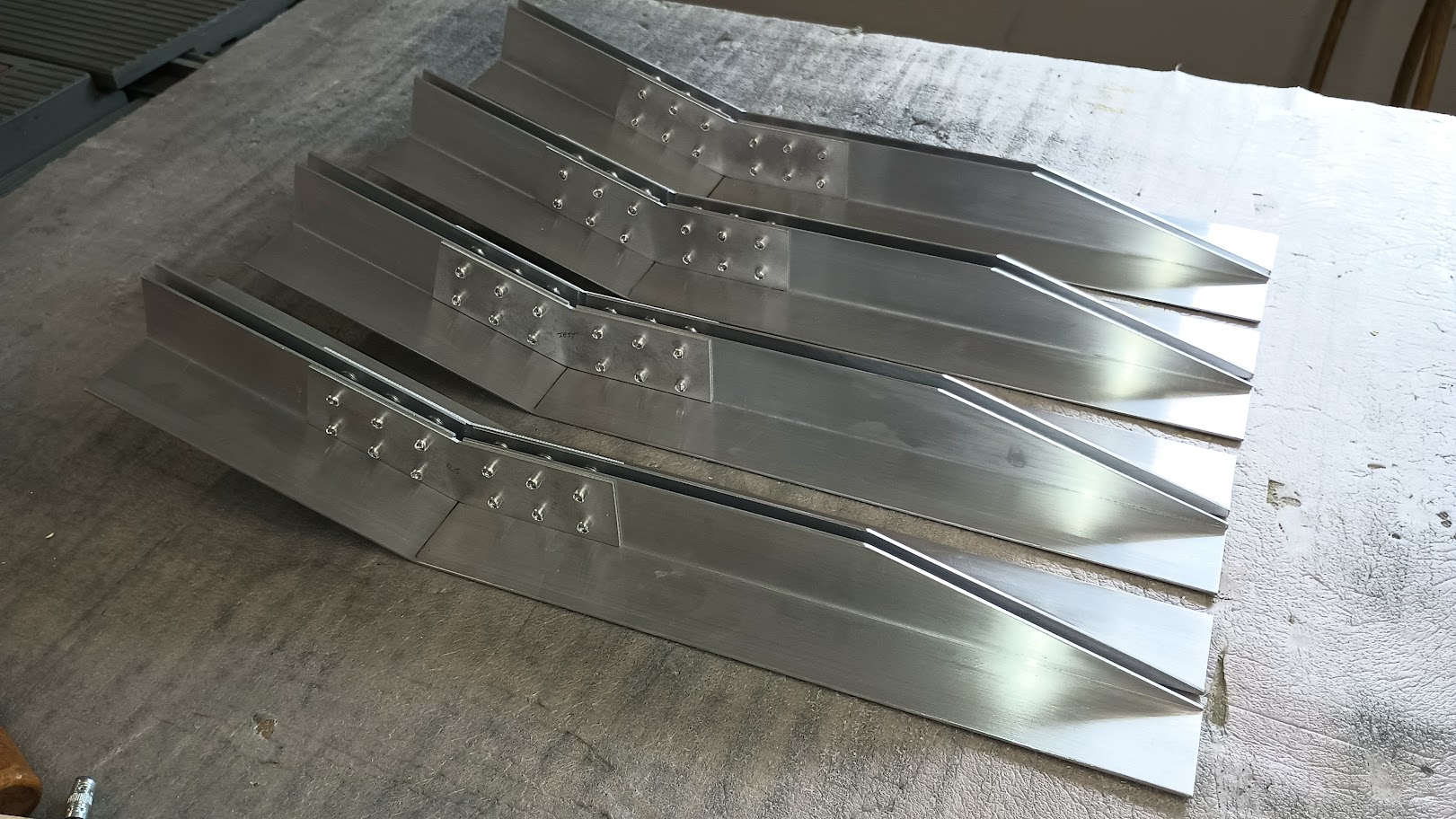
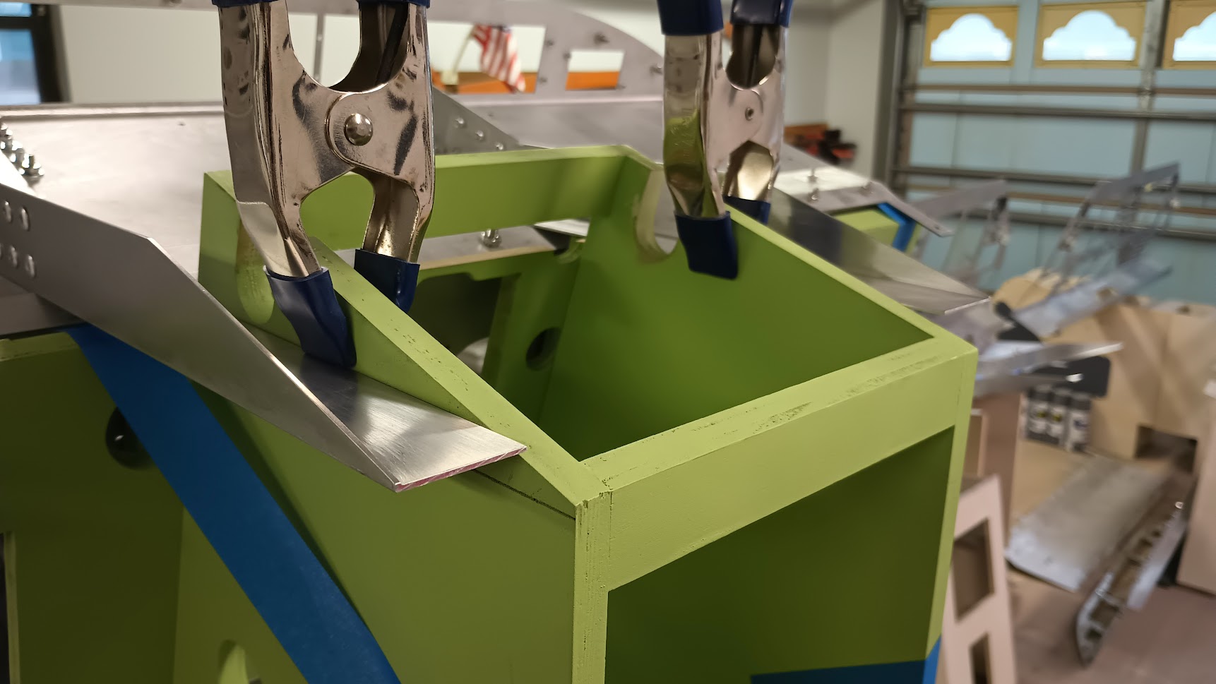
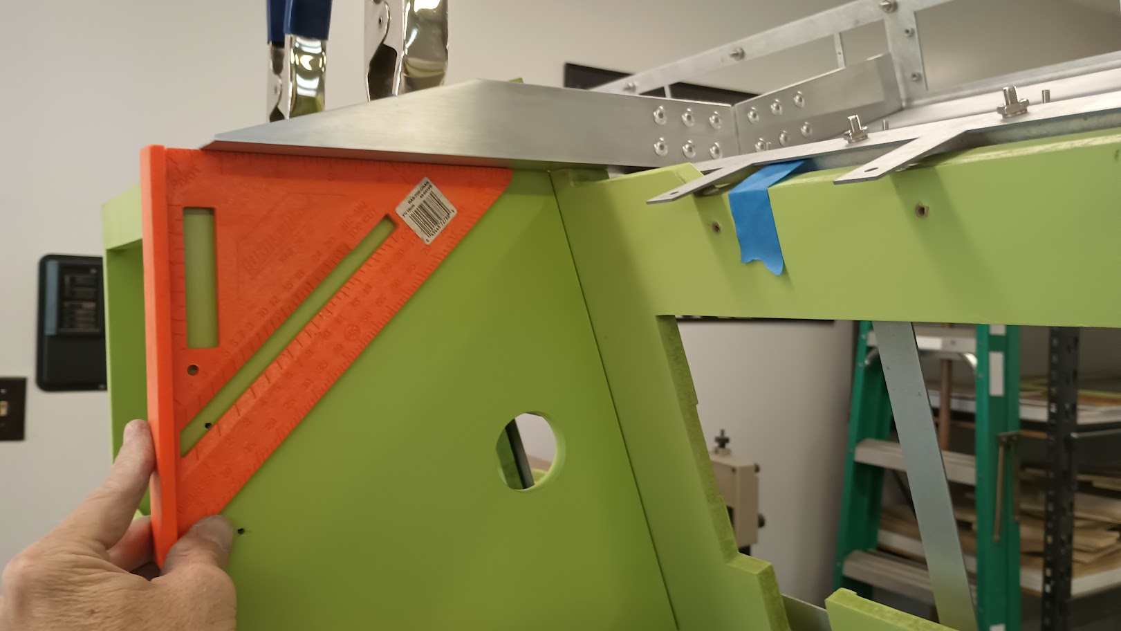
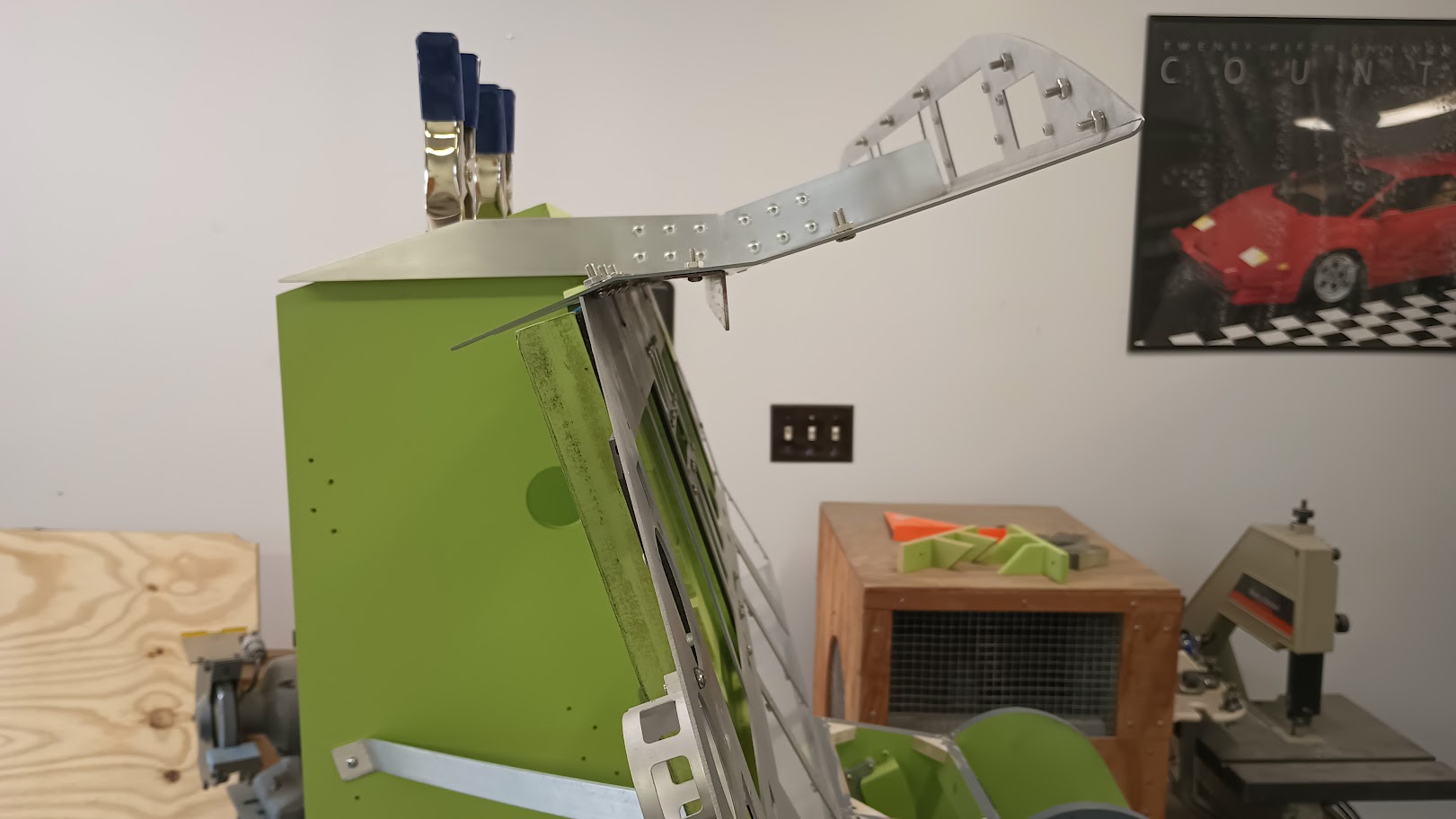
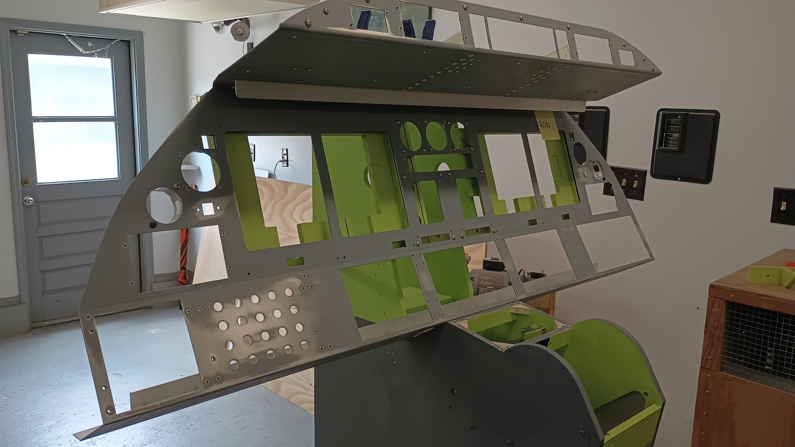
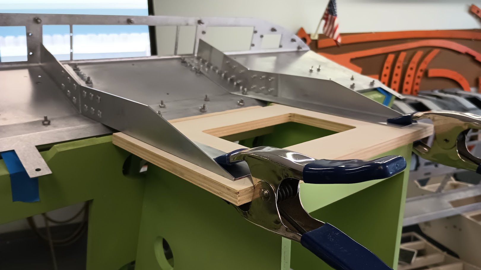
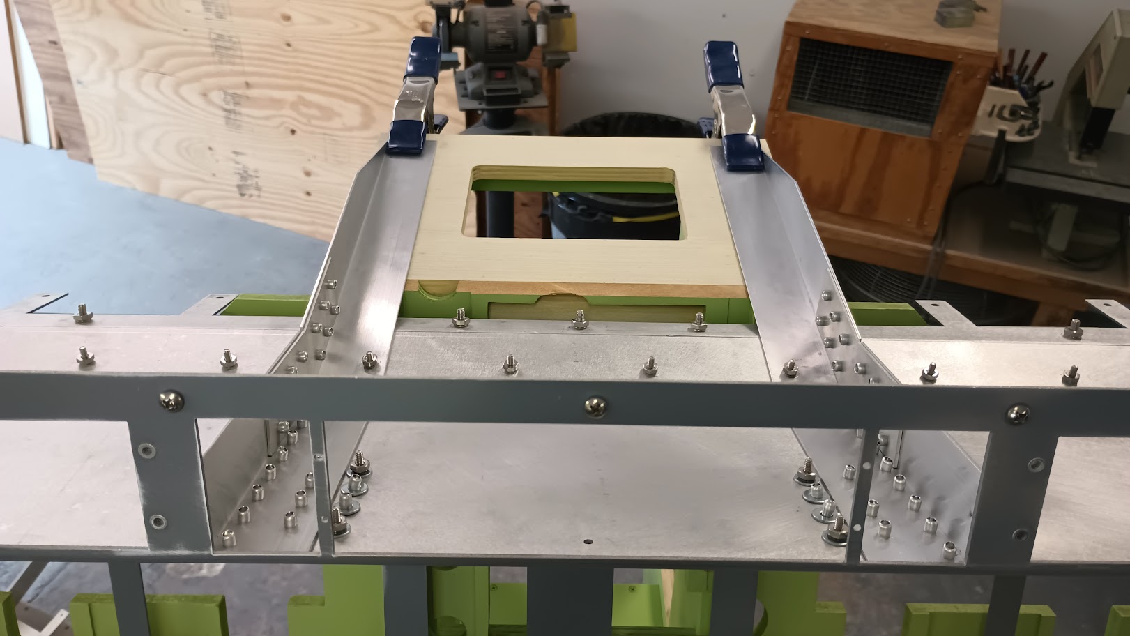
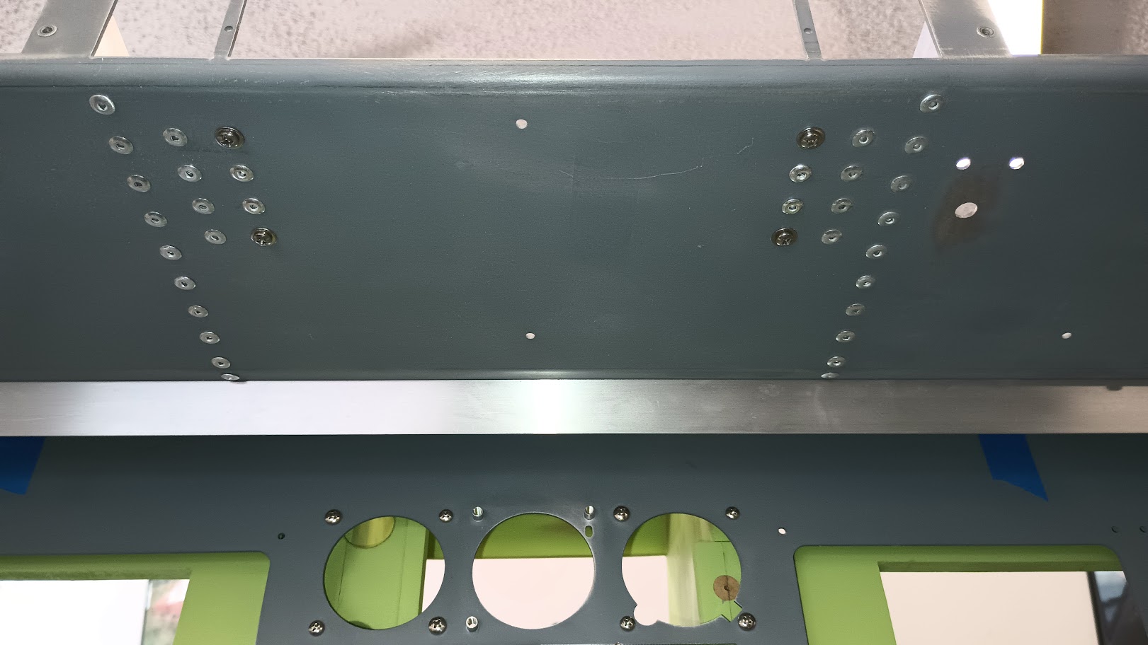
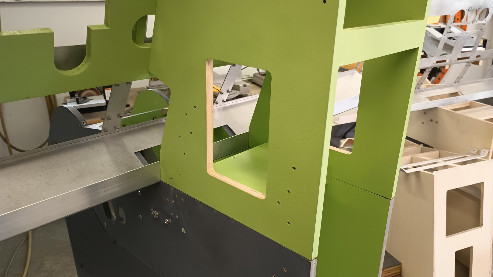
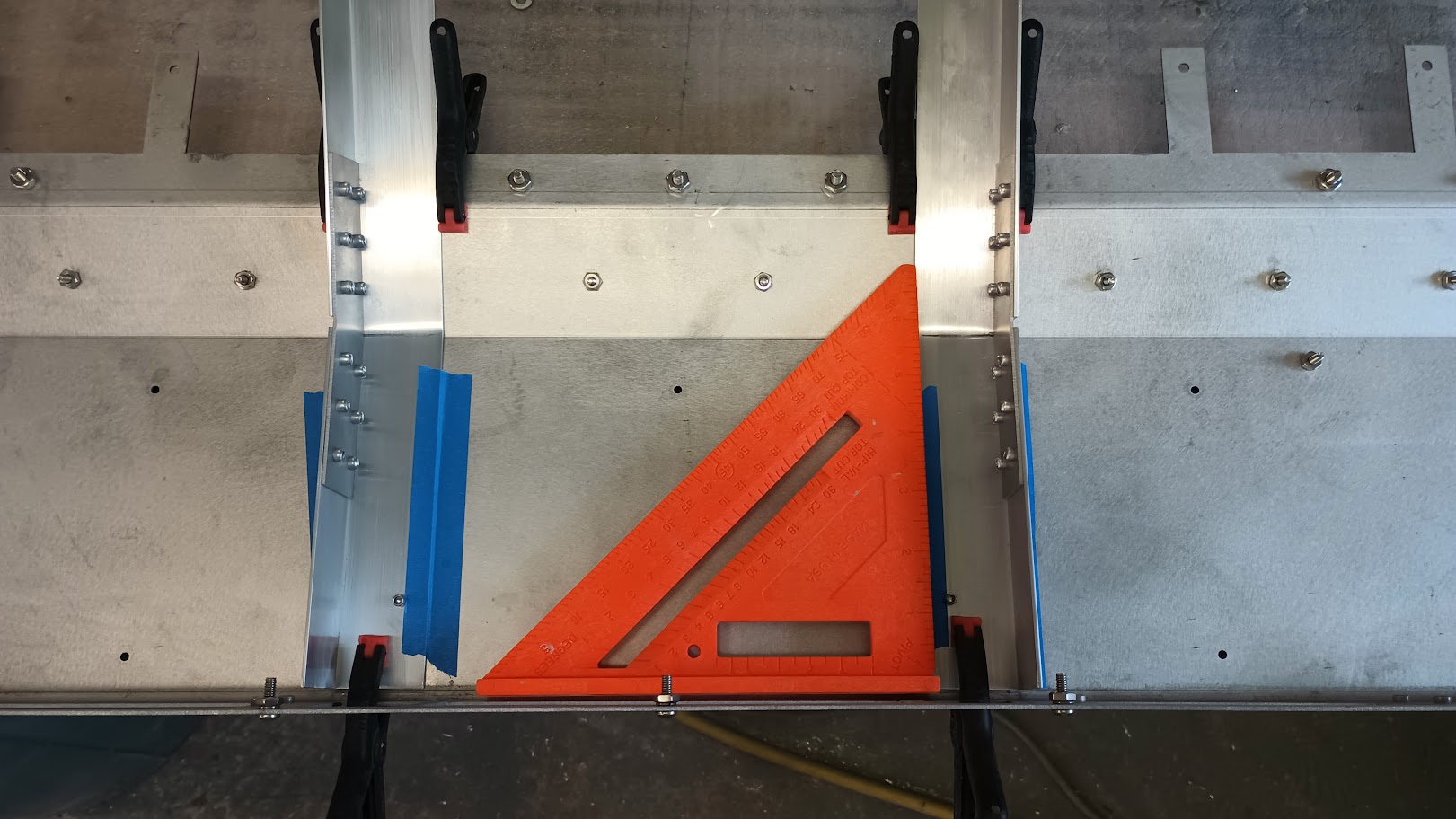
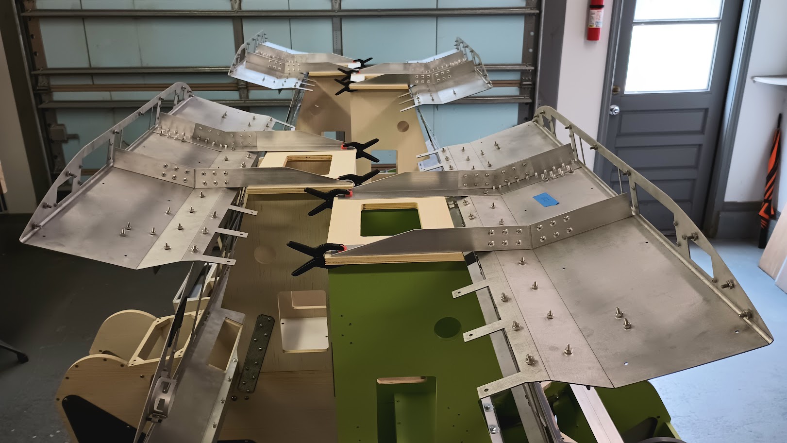
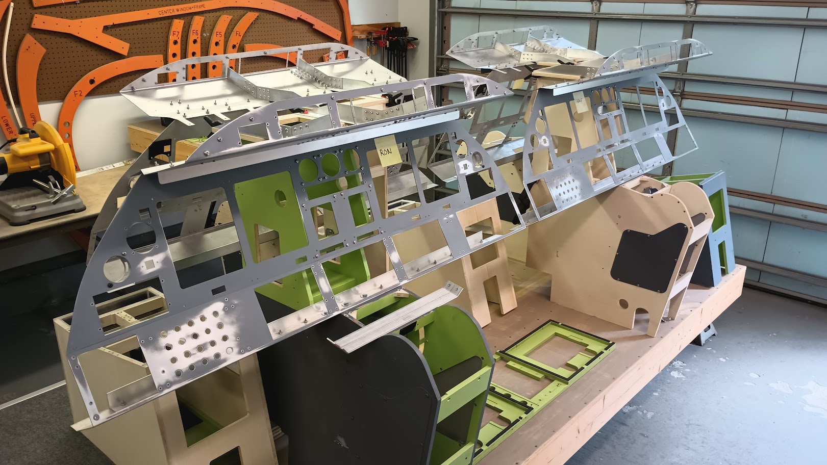
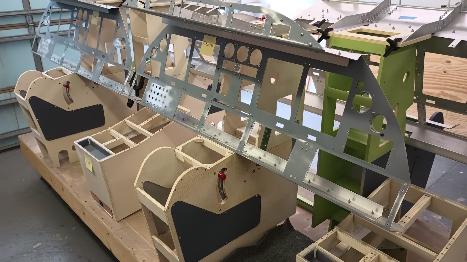
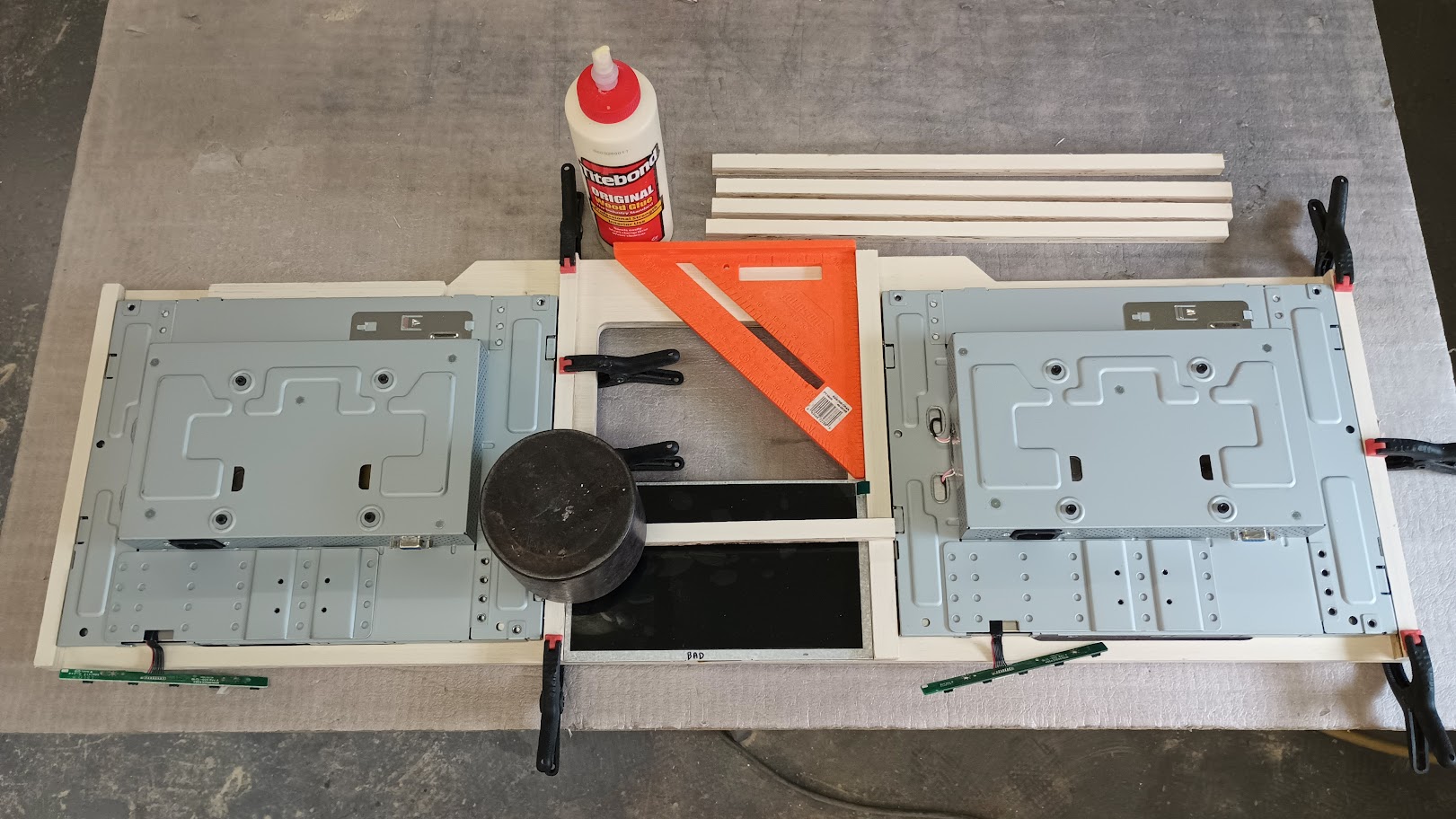
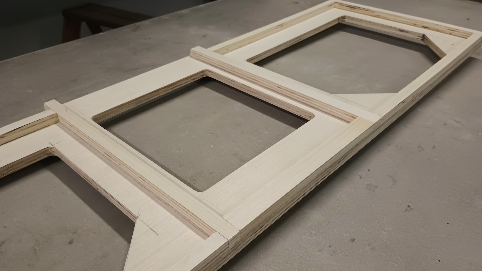
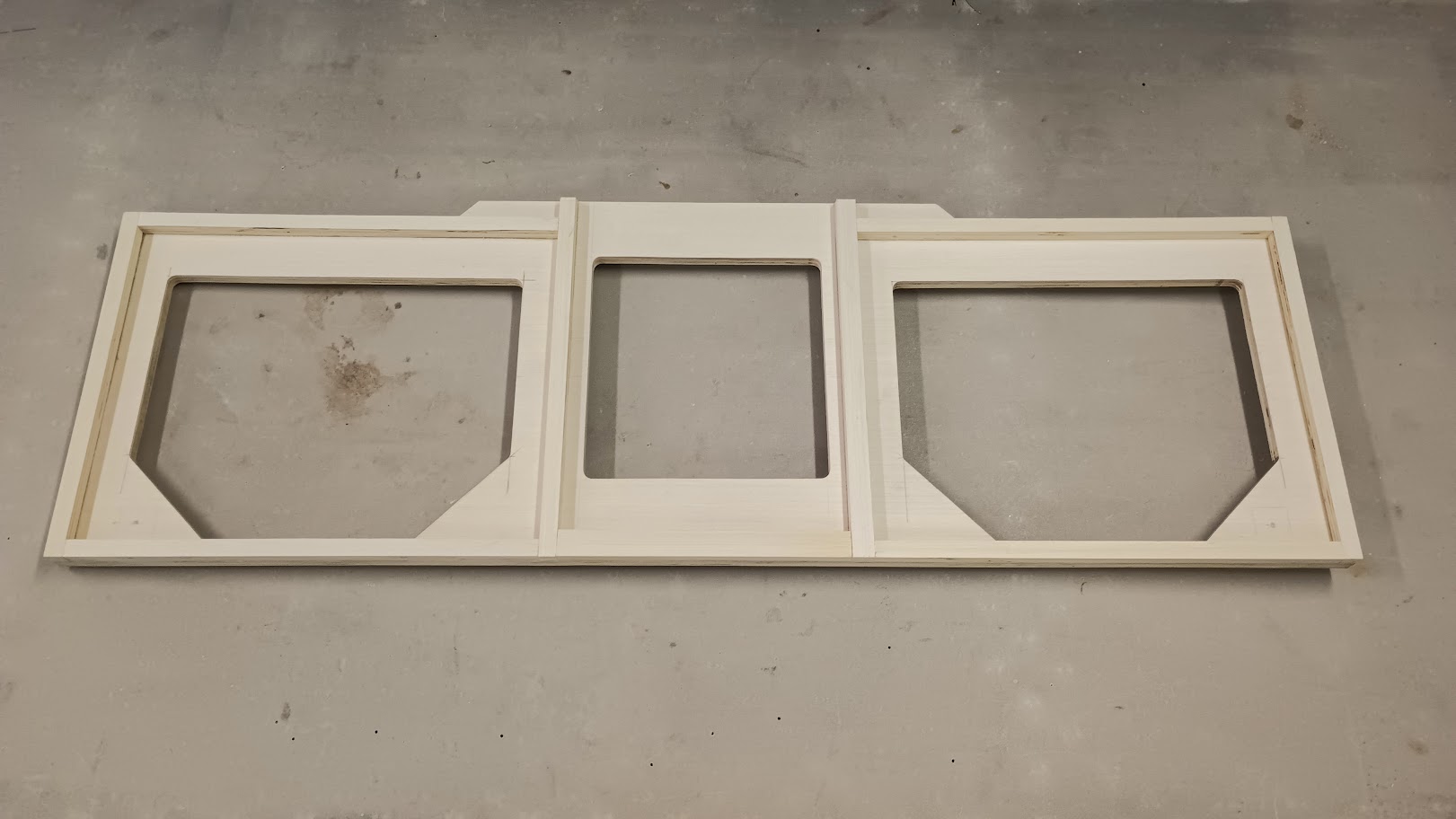
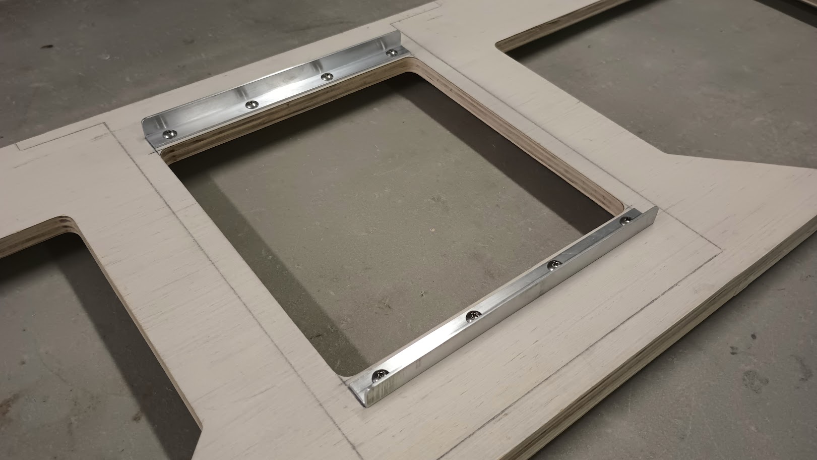
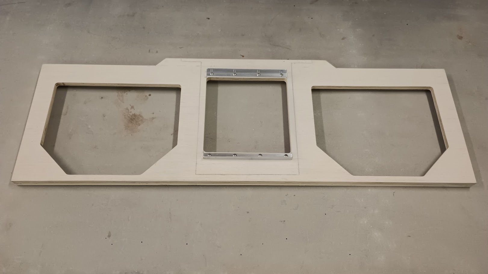
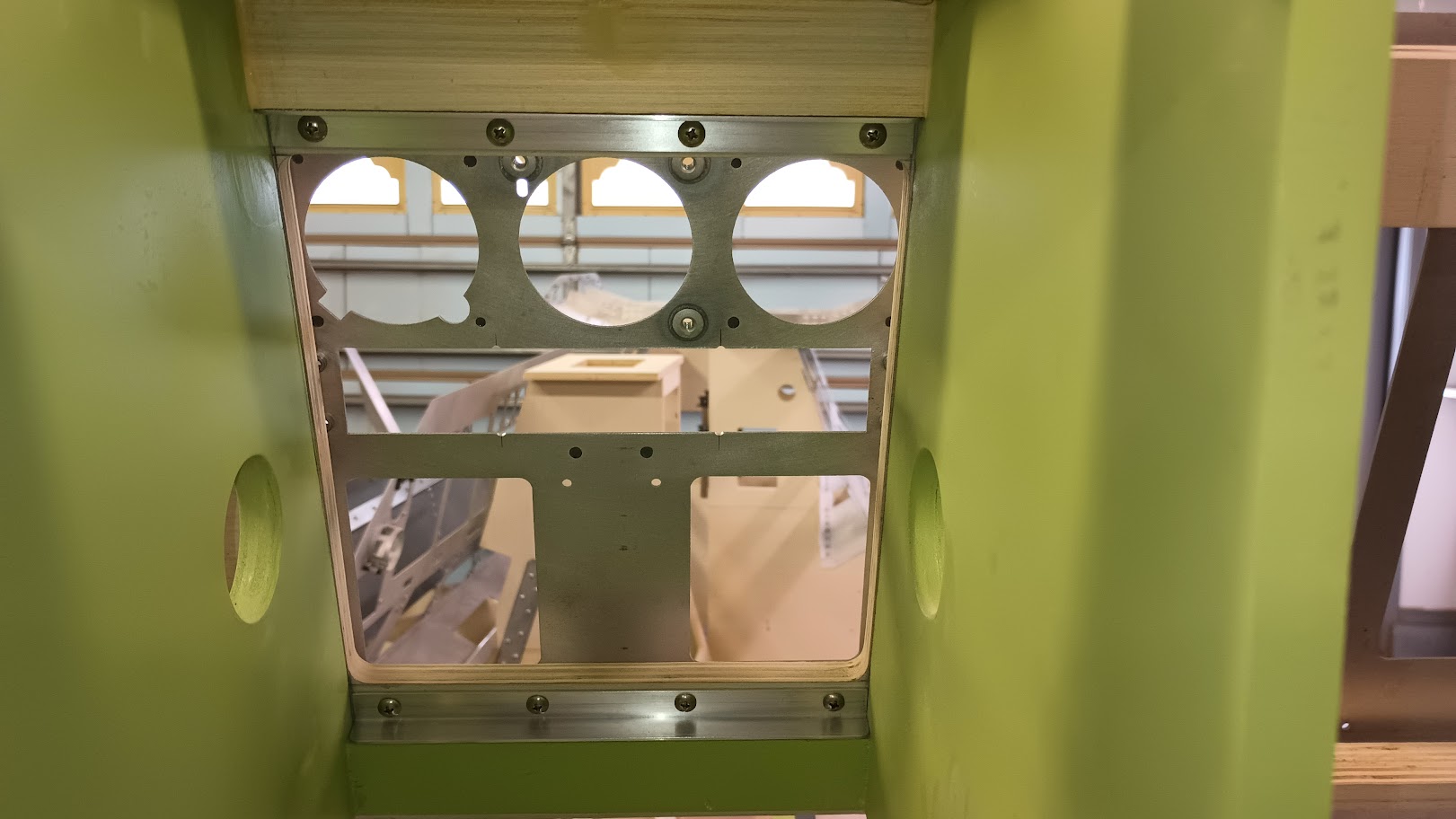
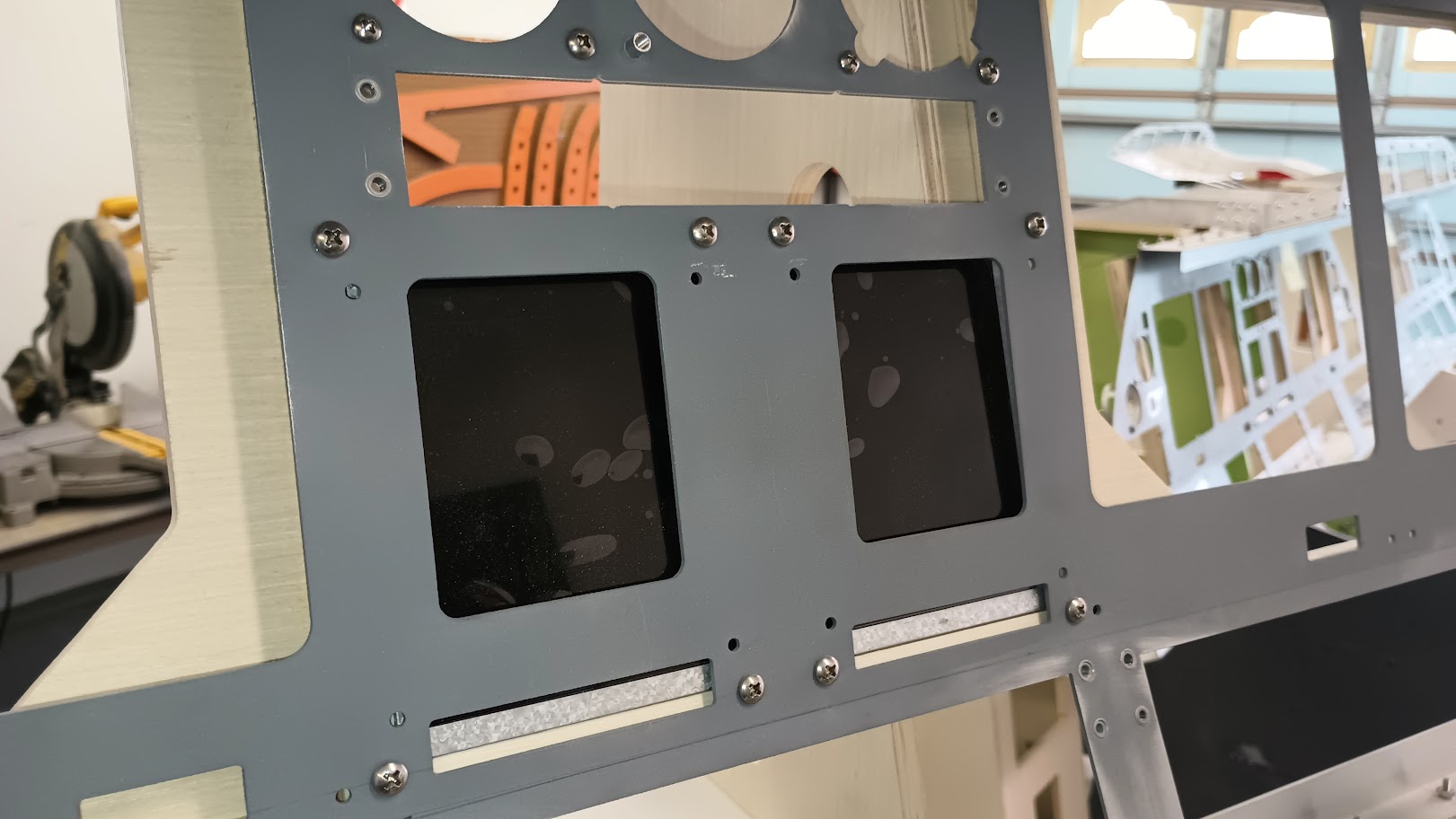
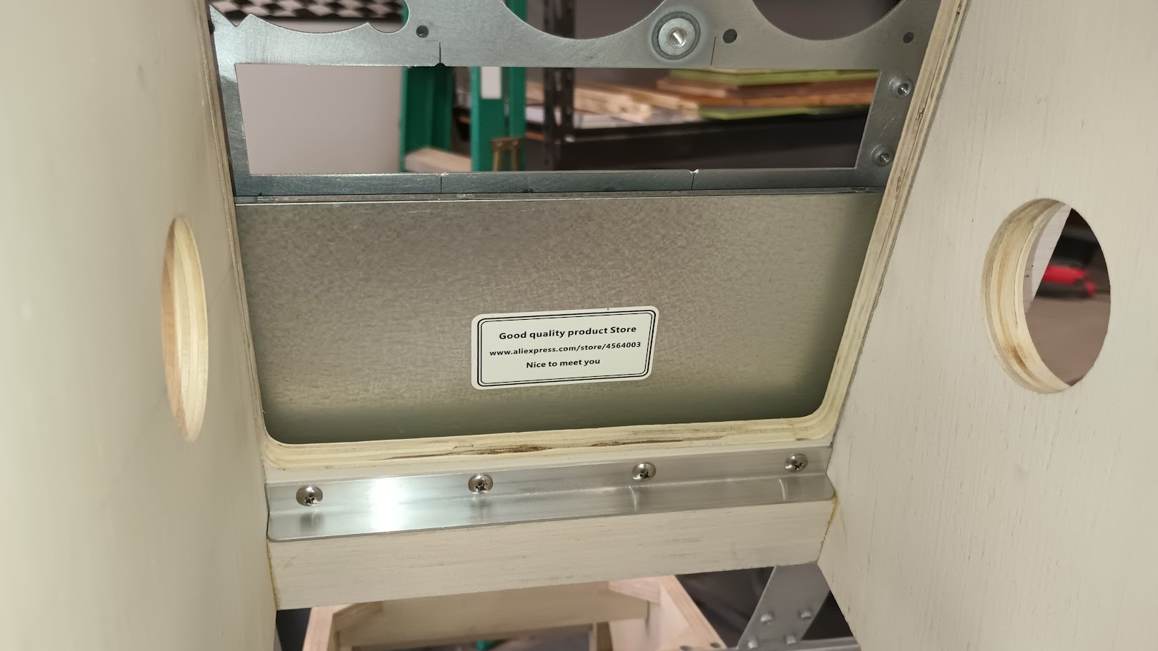
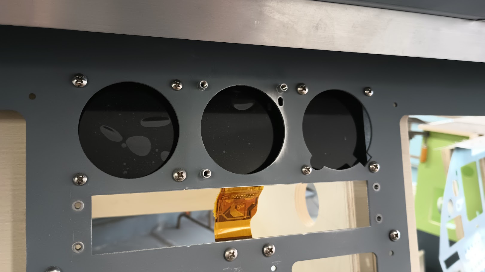
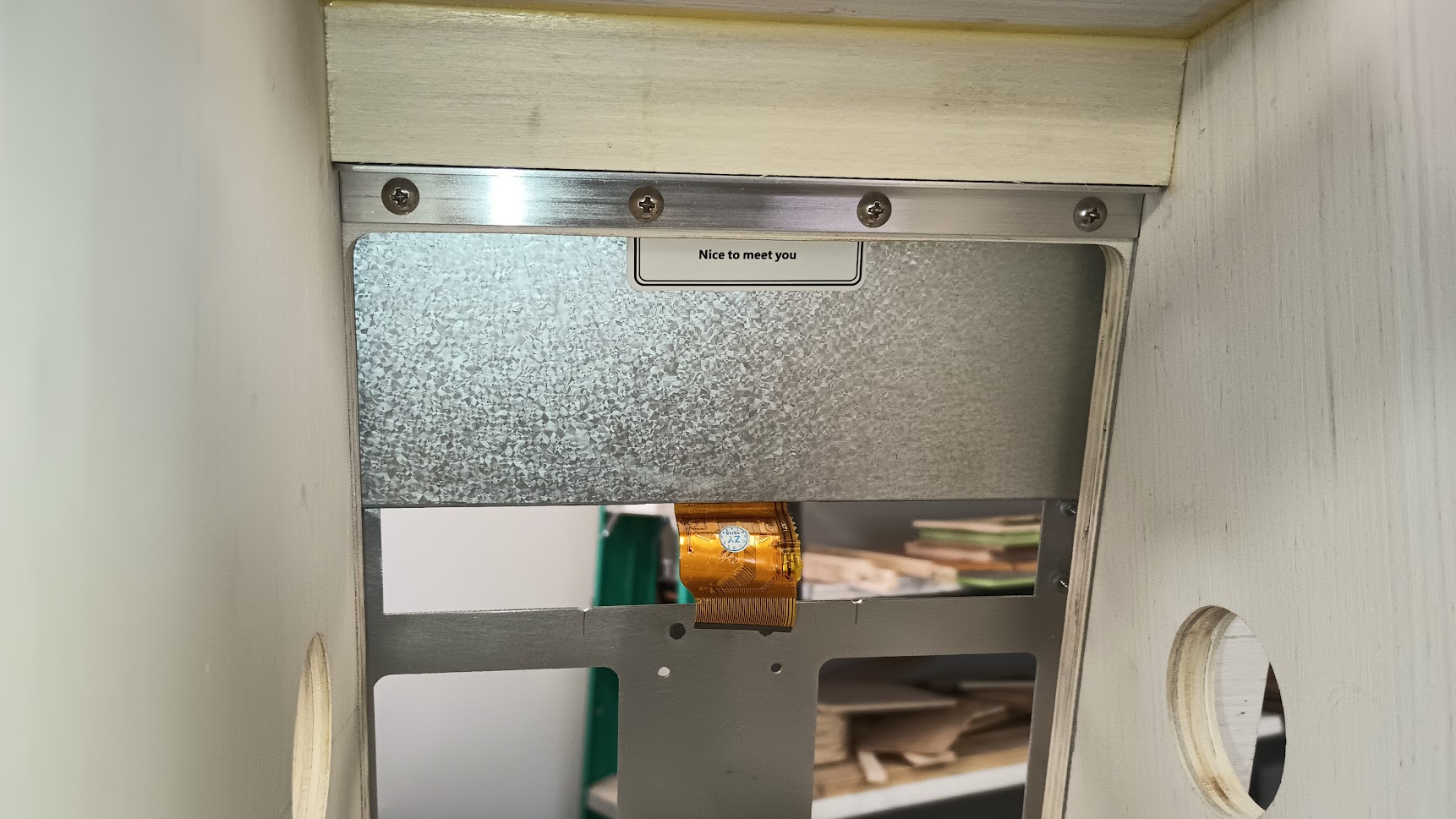
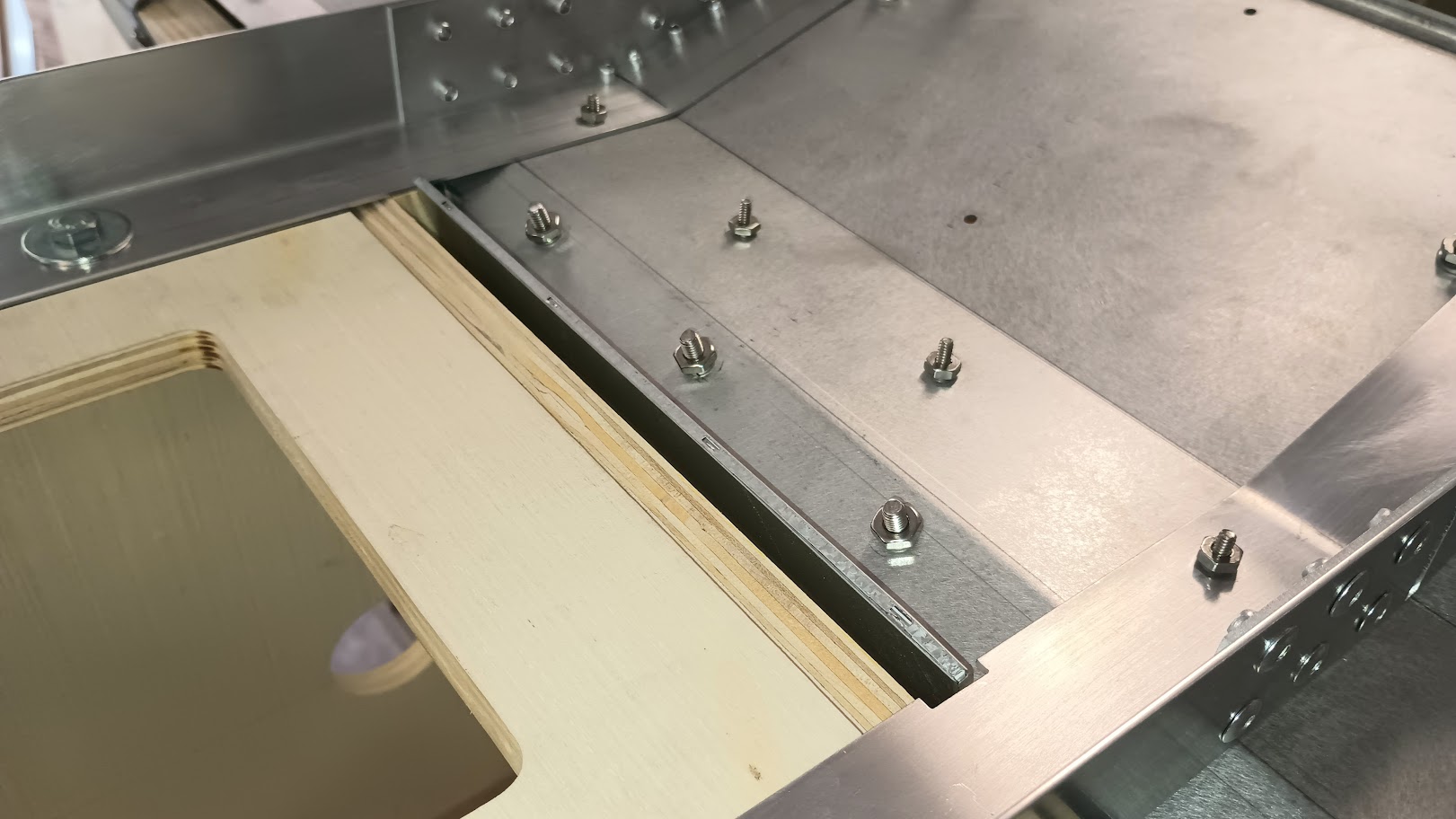
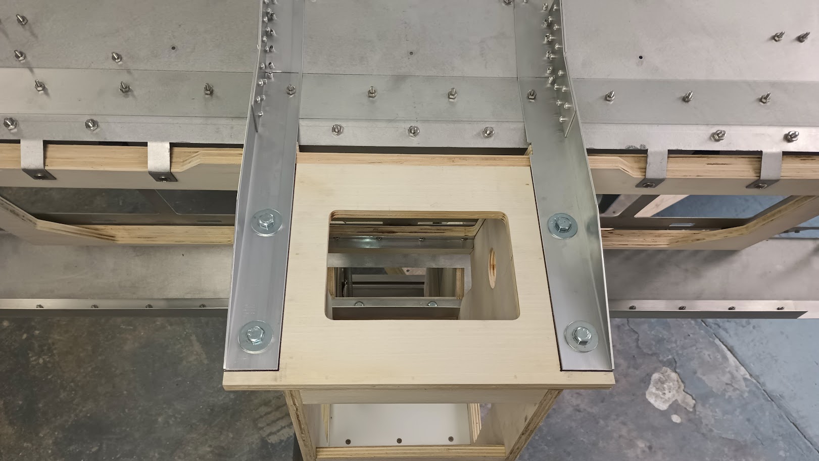
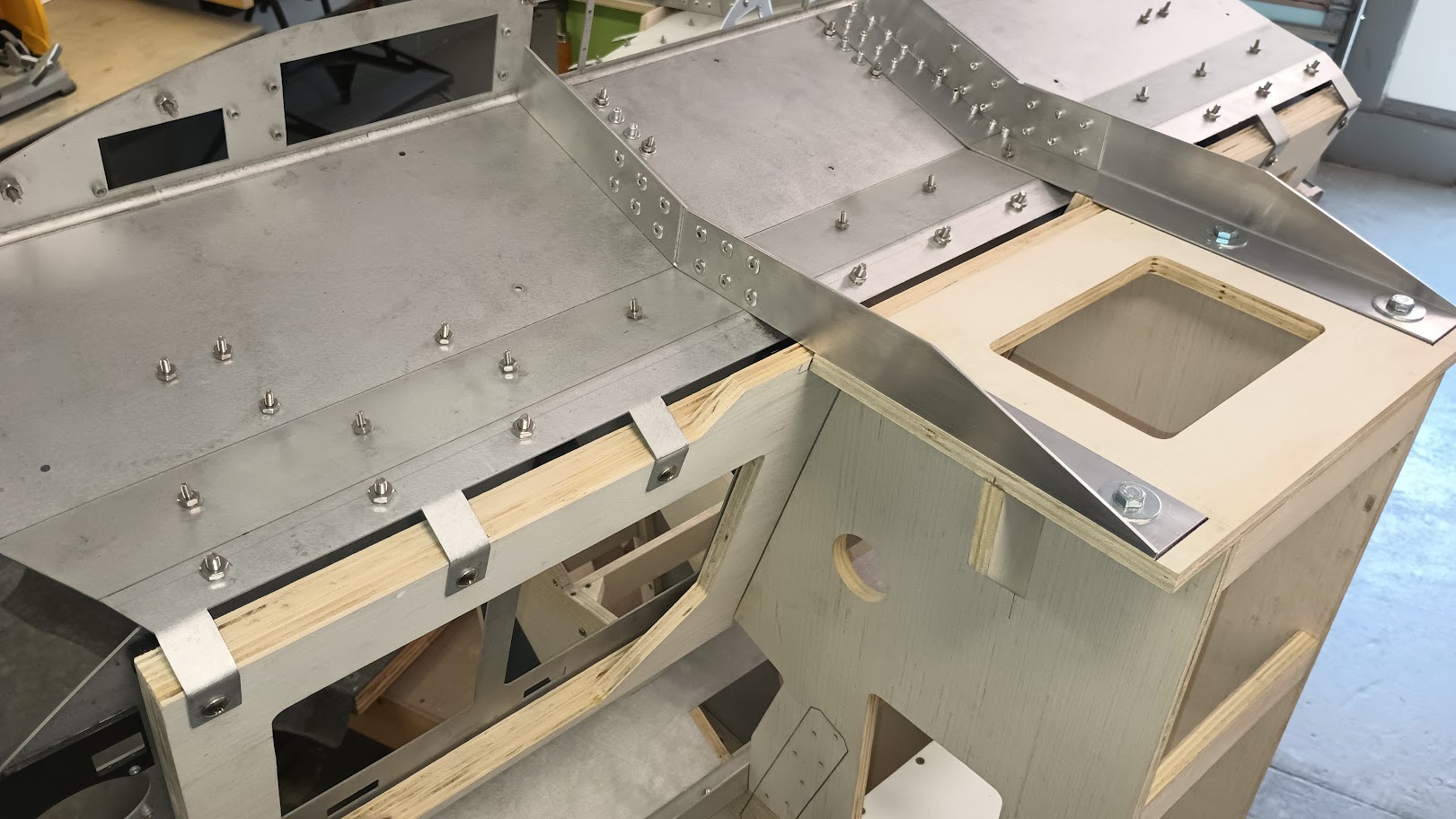
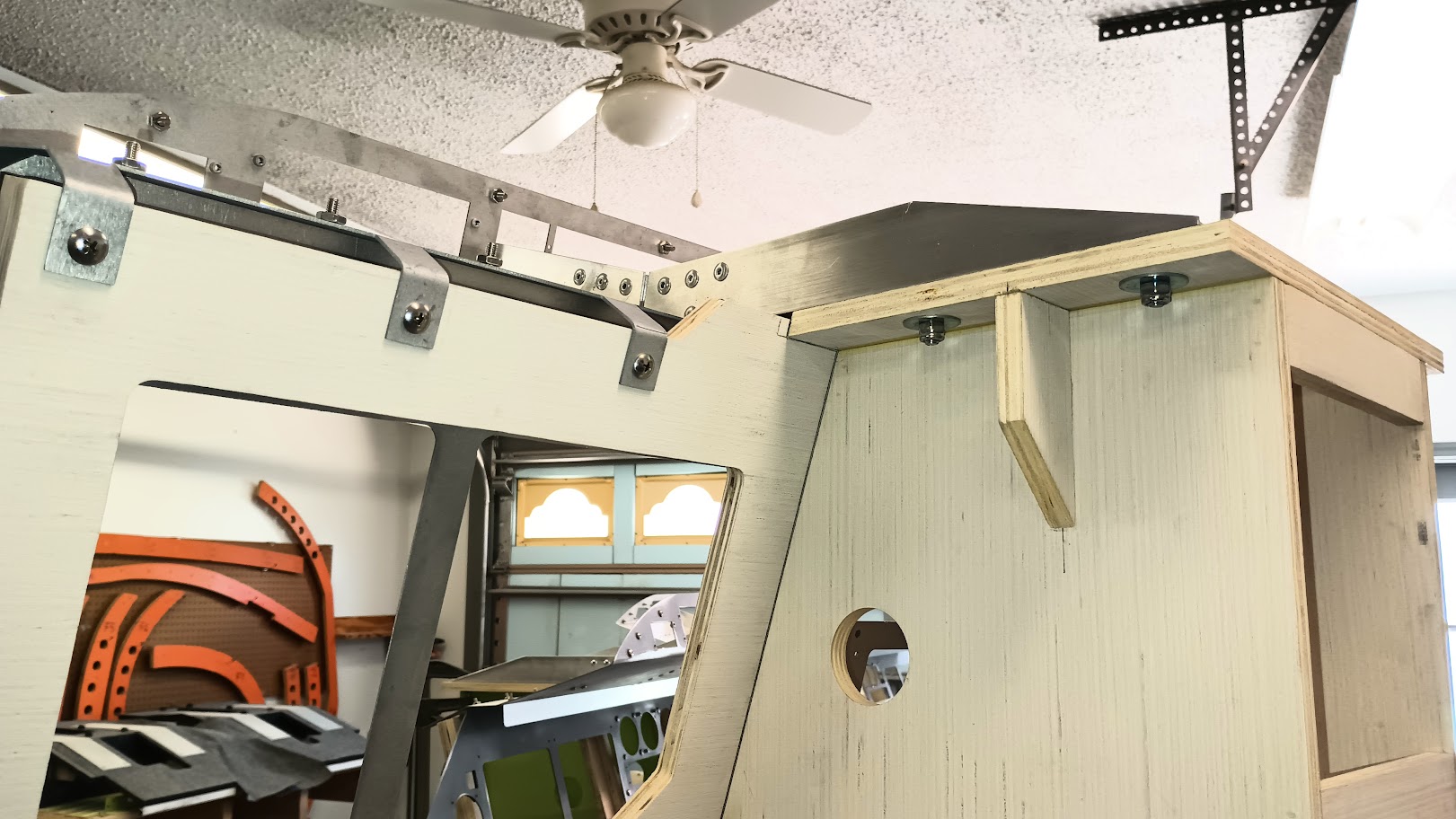
Over the past several weeks I have been working on the new v2.0 Center Pedestal! A quick disclaimer, if you already have a v1.0 Center Pedestal and you are happy with with it, there is no need to build the new v2.0 Center Pedestal unless you are looking for a fun weekend project. Like every other aspect of our build, there was room for improvement with the Center Pedestal. Below is a photo of the v1.0 pedestal to the left with four new v2.0 pedestals about 90% complete! Other than minor dimensional differences, the updates and improvements include: The dxf files and all related G-Code files will be made available once these four pedestals are complete and the design is proven. I will also add that having a cnc machine to make some of these parts is extremely helpful and might be considered absolutely necessary by some in order to achieve some of these parts. As an example, the rear end of the pedestal is cut on the cnc in order to create the space pocket needed to accommodate the phone panel that is built into the pedestal. If you are wondering why the blue painters tape, it helps to eliminate ripping and tearing of the wood. Once the tape is removed, you are left with a crisp clean cut! The photo below shows why the rear end of the pedestal has to be cut on the cnc. Not only is there a rear pocket but also a pedestal divider that is built into the rear piece. The other two pedestal dividers, the forward and middle are made of clear cast plastic. The front divider has also been updated to better replicate what is found in the real Lear45 aircraft. I found that the best way to replicate this area was to us a .25" thick piece of clear cast plastic and tier the top edges with one step down. It is also built directly into the top edge of the pedestal unlike the previous version. Taking a look inside, I added "L" angle rails and 90 degree corner braces to insure that the pedestal is as square as possible. (Later these rails will be used as part of the wire management support) Even working with the highest quality wood, you will find that it can be slightly warped and the thickness can vary. In the case of the Center Pedestal and the TQ Pedestal for that matter, the thickness needs to be .5". Any more or less and you will run into issues. The photo above shows the rear lower maintenance access panel from the inside. The photo below shows the same from the outside. A piano hinge is cut to size and used to open the access panel fully. I believe this access is for maintenance use, however, we can use this for USB and port connections for our own version of "maintenance performance actions". Still to be completed is working in the middle pedestal dividers. In the photo below you can see that I am insuring I have proper spacing for the divider by using a couple panels. Notice how tight the tolerances are? One of the last things before final sanding and painting is to install the Rivnuts. I opted to keep it simple, a little cheaper and a little quicker by only installing the forty four Rivnuts needed to install all the panels. Otherwise we are looking at 172 Rivnuts to be installed. (Could be a rainy day project if you have a spare $100 to spend) It goes without saying that the placement of all forty four Rivnuts has to be perfectly precise! To do this with a great degree of confidence I made two .25" thick clear cast jigs with the cnc machine. A upper jig for above the bend and a lower jig for under. I will have more photos on this and the completion of the Center Pedestal in a week! Over the past several weeks I have been working on the new v2.0 Center Pedestal! A quick disclaimer, if you already have a v1.0 Center Pedestal and you are happy with with it, there is no need to build the new v2.0 Center Pedestal unless you are looking for a fun weekend project. Like every other aspect of our build, there was room for improvement with the Center Pedestal. Below is a photo of the v1.0 pedestal to the left with four new v2.0 pedestals about 90% complete! Other than minor dimensional differences, the updates and improvements include: The dxf files and all related G-Code files will be made available once these four pedestals are complete and the design is proven. I will also add that having a cnc machine to make some of these parts is extremely helpful and might be considered absolutely necessary by some in order to achieve some of these parts. As an example, the rear end of the pedestal is cut on the cnc in order to create the space pocket needed to accommodate the phone panel that is built into the pedestal. If you are wondering why the blue painters tape, it helps to eliminate ripping and tearing of the wood. Once the tape is removed, you are left with a crisp clean cut! The photo below shows why the rear end of the pedestal has to be cut on the cnc. Not only is there a rear pocket but also a pedestal divider that is built into the rear piece. The other two pedestal dividers, the forward and middle are made of clear cast plastic. The front divider has also been updated to better replicate what is found in the real Lear45 aircraft. I found that the best way to replicate this area was to us a .25" thick piece of clear cast plastic and tier the top edges with one step down. It is also built directly into the top edge of the pedestal unlike the previous version. Taking a look inside, I added "L" angle rails and 90 degree corner braces to insure that the pedestal is as square as possible. (Later these rails will be used as part of the wire management support) Even working with the highest quality wood, you will find that it can be slightly warped and the thickness can vary. In the case of the Center Pedestal and the TQ Pedestal for that matter, the thickness needs to be .5". Any more or less and you will run into issues. The photo above shows the rear lower maintenance access panel from the inside. The photo below shows the same from the outside. A piano hinge is cut to size and used to open the access panel fully. I believe this access is for maintenance use, however, we can use this for USB and port connections for our own version of "maintenance performance actions". Still to be completed is working in the middle pedestal dividers. In the photo below you can see that I am insuring I have proper spacing for the divider by using a couple panels. Notice how tight the tolerances are? One of the last things before final sanding and painting is to install the Rivnuts. I opted to keep it simple, a little cheaper and a little quicker by only installing the forty four Rivnuts needed to install all the panels. Otherwise we are looking at 172 Rivnuts to be installed. (Could be a rainy day project if you have a spare $100 to spend) It goes without saying that the placement of all forty four Rivnuts has to be perfectly precise! To do this with a great degree of confidence I made two .25" thick clear cast jigs with the cnc machine. A upper jig for above the bend and a lower jig for under. I will have more photos on this and the completion of the Center Pedestal in a week! Ron, beautiful work as per usual. When you say you are installing “rivnuts”, are you using the sheet metal compression type? I suggest you use “threaded inserts” (eg: Rockler Threaded inserts ). No risk of blowing out your timber, probably more secure, and not expensive. Don’t need long inserts as they are just for holding the panel in place, there should be no pulling pressure on the screws. I have found through rigorous scientific testing in Mark S’s sim that in event of a crash there is absolutely no risk of an inverted impact or roll-over on the shell (yes Mark, and you just thought all those crashes were due to ineptitude! Ha!!😎). Therefore only light holding force is required. Ron, beautiful work as per usual. When you say you are installing “rivnuts”, are you using the sheet metal compression type? I suggest you use “threaded inserts” (eg: Rockler Threaded inserts ). No risk of blowing out your timber, probably more secure, and not expensive. Don’t need long inserts as they are just for holding the panel in place, there should be no pulling pressure on the screws. I have found through rigorous scientific testing in Mark S’s sim that in event of a crash there is absolutely no risk of an inverted impact or roll-over on the shell (yes Mark, and you just thought all those crashes were due to ineptitude! Ha!!😎). Therefore only light holding force is required. Hey Will, Yes, I plan to use Rivnuts. I looked into and tried a couple different types of threaded inserts did not like them. At least the two types I tried. The main issue was that because the hole is so close to the edge of the wood that I ended up with swelling on the outside of the pedestal. I am using the Rivnuts a little differently than they are designed to be used. Instead of installing them and pulling them well into themselves as designed, I am only giving them something like a twist and a half. I twist the tool until I hear the snap and then another half twist, that's it. Just that little bit of twisting is plenty enough to hold the Rivnut in place securely. On the other hand, if I kept twisting, it would blow out the wood as you can imagine. The photo below is of the TQ Pedestal where the System Test panel mounts. Here we need both size 6 and size 8 screws/Rivnuts. Works perfectly and is as secure as we will ever need. One cool thing that I discovered is that because the thread in the Rivnuts that the screws screw into is about a 1/8" deep into the Rivnut body, a screw that is 1/2" long only gets about one full turn before it is secure and holding the panel in place. Kinda like the way real DZUS rails and fasteners work. If a builder does not like the "one turn" feel, they can get the little bit longer screws, 5/8" long. Hey Will, Yes, I plan to use Rivnuts. I looked into and tried a couple different types of threaded inserts did not like them. At least the two types I tried. The main issue was that because the hole is so close to the edge of the wood that I ended up with swelling on the outside of the pedestal. I am using the Rivnuts a little differently than they are designed to be used. Instead of installing them and pulling them well into themselves as designed, I am only giving them something like a twist and a half. I twist the tool until I hear the snap and then another half twist, that's it. Just that little bit of twisting is plenty enough to hold the Rivnut in place securely. On the other hand, if I kept twisting, it would blow out the wood as you can imagine. The photo below is of the TQ Pedestal where the System Test panel mounts. Here we need both size 6 and size 8 screws/Rivnuts. Works perfectly and is as secure as we will ever need. One cool thing that I discovered is that because the thread in the Rivnuts that the screws screw into is about a 1/8" deep into the Rivnut body, a screw that is 1/2" long only gets about one full turn before it is secure and holding the panel in place. Kinda like the way real DZUS rails and fasteners work. If a builder does not like the "one turn" feel, they can get the little bit longer screws, 5/8" long. The new v2.0 Center Pedestals are now all but complete! Just some primer, paint and flat clear coat, that's it. If you would like to build your own or make some updates to your current v1.0 Center Pedestal, the dxf is attached at the bottom of this post. It will also be made available in the Builder Resources page. Let me walk you through the last details of the new Center Pedestals. First, the middle dividers were installed. They are clear cast plastic and have four tabs that are embedded into the wood. Once the wood glue dries, these dividers become a solid part of the pedestal. Next I used my DZUS jigs (made with the cnc) as drill guides to place the holes as precisely as possible. This method proved to work near flawlessly! There was only on hole where I accidentally put a finishing nail too high and in the path of where the drill holes would be. Easy fix. Based on the Center Pedestal panel layout that we have adopted, there are 44 Rivnuts needed to keep all the panels secure. The panels can be swapped around but the configuration we are using seems to be the most common and preferred. In case you are not aware how Rivnuts work, they are designed to be pulled into themselves and squeezed up against the sheet metal/aluminum. However, I found that they also work with wood. When the Rivnuts pull into themselves, they swell and compress against the walls in the wood holes which hold them in place. Here is one getting ready to be pressed into it's hole. I used a tap and hammer to gently push the Rivnuts flush into the wood. This is the Rivnut tool used to pull the Rivnuts into themselves. A couple turns and you can feel the Rivnut snap and then start to pull into itself. A couple more turns and you can feel that the Rivnut is firmly in place. I am not sure what the "torque" figure would be but in all cases, I did it by hand and feel without splitting any wood! The final product is a flush and secure Rivnut that is exactly in the right place! After all the Rivnuts were securely in place, the moment of truth was doing a test fit. Success! What you are looking at is a mix of some v.20 panels with some v1.0 panels. You might notice a slight difference in color of some of the panels. The fit of the v2.0 panels is perfect while the v1.0 panels are just a tad tight but not a big deal. A typical v1.0 panel is 5.75" wide, while a typical v2.0 panel is 5.745" wide. This reduction of .005" is all it takes to give the new panels the tiny bit of wiggle room they need. Again, no worries because as you can see, everything fits and lines up perfectly! Here is a closer look at the top divider. Notice it is two tier? I tried to model this as close to what is found in the real Lear45 based on a couple photos. Probably not exactly what the real part looks like but as close as we can get without holding it in our hands! The middle divider is flush with the panels it boarders with and serves it's purpose as a.....well, a divider. It might be hard to tell from this photo but the divider is centered on the pedestal angle. Last but not least, the rear divider. The best way I found to replicate this one was to build it in with the wood. The access panel at the lower rear of the Center Pedestal is access to a service panel that most likely allows maintenance personnel to gain access to DEEC connection terminals to download engine performance data, etc. This is something that we will never model so I decided to fill this access panel with something that we might find useful. Here the panel is up and secure. On the left side is a dual USB connection which will come in handy to charge cell phones and iPads. The middle area is a cut out to pass cables and wires through the Center Pedestal. This might come in handy if we are trouble shooting one of the CDUs and we are looking for an easy access/shortcut. Last but not least, a 110 outlet. And a quick view of what the panel looks like form the inside. One other point about this panel, it is super easy to make and if in the future we need to add something or make modifications, no problem. Seven screws and the panel is removed! And that is the the new v2.0 Center Pedestal! As of right now, I have one spare available for sale and one v1.0 Center Pedestal that has been modified and updated with the Rivnuts. In other words, all panels will mount to the v1.0 pedestal the same way they will mount to the v2.0 pedestal. Any questions on the Center Pedestal, please ask. Don't forget to download the Center Pedestal Master dxf if you want to build one for yourself! The new v2.0 Center Pedestals are now all but complete! Just some primer, paint and flat clear coat, that's it. If you would like to build your own or make some updates to your current v1.0 Center Pedestal, the dxf is attached at the bottom of this post. It will also be made available in the Builder Resources page. Let me walk you through the last details of the new Center Pedestals. First, the middle dividers were installed. They are clear cast plastic and have four tabs that are embedded into the wood. Once the wood glue dries, these dividers become a solid part of the pedestal. Next I used my DZUS jigs (made with the cnc) as drill guides to place the holes as precisely as possible. This method proved to work near flawlessly! There was only on hole where I accidentally put a finishing nail too high and in the path of where the drill holes would be. Easy fix. Based on the Center Pedestal panel layout that we have adopted, there are 44 Rivnuts needed to keep all the panels secure. The panels can be swapped around but the configuration we are using seems to be the most common and preferred. In case you are not aware how Rivnuts work, they are designed to be pulled into themselves and squeezed up against the sheet metal/aluminum. However, I found that they also work with wood. When the Rivnuts pull into themselves, they swell and compress against the walls in the wood holes which hold them in place. Here is one getting ready to be pressed into it's hole. I used a tap and hammer to gently push the Rivnuts flush into the wood. This is the Rivnut tool used to pull the Rivnuts into themselves. A couple turns and you can feel the Rivnut snap and then start to pull into itself. A couple more turns and you can feel that the Rivnut is firmly in place. I am not sure what the "torque" figure would be but in all cases, I did it by hand and feel without splitting any wood! The final product is a flush and secure Rivnut that is exactly in the right place! After all the Rivnuts were securely in place, the moment of truth was doing a test fit. Success! What you are looking at is a mix of some v.20 panels with some v1.0 panels. You might notice a slight difference in color of some of the panels. The fit of the v2.0 panels is perfect while the v1.0 panels are just a tad tight but not a big deal. A typical v1.0 panel is 5.75" wide, while a typical v2.0 panel is 5.745" wide. This reduction of .005" is all it takes to give the new panels the tiny bit of wiggle room they need. Again, no worries because as you can see, everything fits and lines up perfectly! Here is a closer look at the top divider. Notice it is two tier? I tried to model this as close to what is found in the real Lear45 based on a couple photos. Probably not exactly what the real part looks like but as close as we can get without holding it in our hands! The middle divider is flush with the panels it boarders with and serves it's purpose as a.....well, a divider. It might be hard to tell from this photo but the divider is centered on the pedestal angle. Last but not least, the rear divider. The best way I found to replicate this one was to build it in with the wood. The access panel at the lower rear of the Center Pedestal is access to a service panel that most likely allows maintenance personnel to gain access to DEEC connection terminals to download engine performance data, etc. This is something that we will never model so I decided to fill this access panel with something that we might find useful. Here the panel is up and secure. On the left side is a dual USB connection which will come in handy to charge cell phones and iPads. The middle area is a cut out to pass cables and wires through the Center Pedestal. This might come in handy if we are trouble shooting one of the CDUs and we are looking for an easy access/shortcut. Last but not least, a 110 outlet. And a quick view of what the panel looks like form the inside. One other point about this panel, it is super easy to make and if in the future we need to add something or make modifications, no problem. Seven screws and the panel is removed! And that is the the new v2.0 Center Pedestal! As of right now, I have one spare available for sale and one v1.0 Center Pedestal that has been modified and updated with the Rivnuts. In other words, all panels will mount to the v1.0 pedestal the same way they will mount to the v2.0 pedestal. Any questions on the Center Pedestal, please ask. Don't forget to download the Center Pedestal Master dxf if you want to build one for yourself! I finally caught up on some other projects and have started back on that last push to complete the development of the new v2.0 furniture pieces! To recap, I have the aluminum MIP and Glareshield cut with Rivet Nuts inserted and a lot of the hardware mounted. The new v2.0 TQ Pedestal and Center Pedestal are both complete. There are three major areas that still need to be redesigned and built: It took me a full day to get my head wrapped back around this project because there are so many changes happening all at the same time. One of the biggest changes is switching to the two 9" LCD screens taking place of the single center LCD screen. Another is the new CWP that falls behind the MIP. Yet another big change is the new v2.0 Glareshield that now includes one additional bend to better model the real Lear45's Glareshield. There are many other minor changes and adjustments but these are the big ones. What I am discovering is that a change in one area is causing a "ripple effect" in other areas. So it is not just a matter of tweaking existing parts. I am finding that s couple key pieces are going to have to be rebuilt from scratch. The following post are an attempt to document as many changes as possible. To start with, I put the major pieces back together to see what I had and what changes need to be made. One of the minor things I changed was the lower plate that helps hold the MIP Tower to the TQ Pedestal. This piece was in the way and blocks the wires and cables from passing through the opening into the Avionics Bay. This was one of the first pieces I removed and relocated horizontally deeper in the MIP Tower. You can kind of see it's new location in this photo. This view is from the front side of the MIP looking through the GEAR/HYD opening. The piece built into the MIP Tower fits onto a piece on the TQ Pedestal like puzzle pieces snapping together. This new location also helps support the many wiring harnesses running through the MIP Tower to the Avionics Bay. The next thing that I determined is that the height of the MIP Tower did not have to be as high as it was in the past. The reason being is that we are no longer using the wide view LCD in portrait mode. This photo shows where the approximate cut lines will be. I need to wait to make these cuts until I am 100% sure where those cuts will fall and to do that, I need to have the Glareshield brackets built up and installed on the Glareshield. As it turns out, I was able to salvage my MIP Tower with some minor modifications, including the upcoming top cut. However, I will not be able to save the old 1.0 MIP Backer and here is why: The top cut line to remove the unneeded material at the top of the MIP Backer leaves no support. Here is a closer look at the cut line and what little is left behind of the old design. This was the deciding factor to start from scratch with a all new MIP Backer. There are several other changes that need to be made to this piece so it would be easier to start fresh. More on the MIP Backer next week. One of the few pieces of the Lear45 sim project that makes it feel like I am building a real aircraft are the Glareshield brackets. And that is because they require rivets and a little bit of metal fabrication. This is a photo of the raw aluminum materials. I don't want to get too specific on measurements because it is possible that projects can vary from one to the next. But one thing that should be constant are the angles. The main bend in the Glareshield is 18 degrees. I made a wooden jig that was set at 9 degrees, half the angle. You need a decent miter box saw to make this cut and a very steady hand. 9 degrees one way and 9 degrees the other way. The 18 degree bend is pretty straight forward. I used a vice and a piece of wood. Because this "L" angle is aluminum, it bends very easily but is still super strong once the bracket is in place. Painters tape helps secure the bracket in place until there are a couple rivets installed. A drill press is very helpful with this part of the job to insure perfect holes. Rivets are fun. If you have never installed rivets, find something to rivet! The end result is that the part is as strong as if the part was never cut in the first place. I made four sets of Glareshield brackets. And that is because I am building up four complete set of furniture! Because I was running short on time, I figured I would do something less tedious. I went ahead and rough cut all the MIP Backers and MIP Towers in preparation of the work coming up next week! Developing and building up the v2.0 furniture pieces is now priority #1 on my list of things that need to be completed. My goal is to have all four sets finished by September 1st. That's four weeks from now so expect to see three more updates before the final completion post. I think I got a pretty good start! I finally caught up on some other projects and have started back on that last push to complete the development of the new v2.0 furniture pieces! To recap, I have the aluminum MIP and Glareshield cut with Rivet Nuts inserted and a lot of the hardware mounted. The new v2.0 TQ Pedestal and Center Pedestal are both complete. There are three major areas that still need to be redesigned and built: It took me a full day to get my head wrapped back around this project because there are so many changes happening all at the same time. One of the biggest changes is switching to the two 9" LCD screens taking place of the single center LCD screen. Another is the new CWP that falls behind the MIP. Yet another big change is the new v2.0 Glareshield that now includes one additional bend to better model the real Lear45's Glareshield. There are many other minor changes and adjustments but these are the big ones. What I am discovering is that a change in one area is causing a "ripple effect" in other areas. So it is not just a matter of tweaking existing parts. I am finding that s couple key pieces are going to have to be rebuilt from scratch. The following post are an attempt to document as many changes as possible. To start with, I put the major pieces back together to see what I had and what changes need to be made. One of the minor things I changed was the lower plate that helps hold the MIP Tower to the TQ Pedestal. This piece was in the way and blocks the wires and cables from passing through the opening into the Avionics Bay. This was one of the first pieces I removed and relocated horizontally deeper in the MIP Tower. You can kind of see it's new location in this photo. This view is from the front side of the MIP looking through the GEAR/HYD opening. The piece built into the MIP Tower fits onto a piece on the TQ Pedestal like puzzle pieces snapping together. This new location also helps support the many wiring harnesses running through the MIP Tower to the Avionics Bay. The next thing that I determined is that the height of the MIP Tower did not have to be as high as it was in the past. The reason being is that we are no longer using the wide view LCD in portrait mode. This photo shows where the approximate cut lines will be. I need to wait to make these cuts until I am 100% sure where those cuts will fall and to do that, I need to have the Glareshield brackets built up and installed on the Glareshield. As it turns out, I was able to salvage my MIP Tower with some minor modifications, including the upcoming top cut. However, I will not be able to save the old 1.0 MIP Backer and here is why: The top cut line to remove the unneeded material at the top of the MIP Backer leaves no support. Here is a closer look at the cut line and what little is left behind of the old design. This was the deciding factor to start from scratch with a all new MIP Backer. There are several other changes that need to be made to this piece so it would be easier to start fresh. More on the MIP Backer next week. One of the few pieces of the Lear45 sim project that makes it feel like I am building a real aircraft are the Glareshield brackets. And that is because they require rivets and a little bit of metal fabrication. This is a photo of the raw aluminum materials. I don't want to get too specific on measurements because it is possible that projects can vary from one to the next. But one thing that should be constant are the angles. The main bend in the Glareshield is 18 degrees. I made a wooden jig that was set at 9 degrees, half the angle. You need a decent miter box saw to make this cut and a very steady hand. 9 degrees one way and 9 degrees the other way. The 18 degree bend is pretty straight forward. I used a vice and a piece of wood. Because this "L" angle is aluminum, it bends very easily but is still super strong once the bracket is in place. Painters tape helps secure the bracket in place until there are a couple rivets installed. A drill press is very helpful with this part of the job to insure perfect holes. Rivets are fun. If you have never installed rivets, find something to rivet! The end result is that the part is as strong as if the part was never cut in the first place. I made four sets of Glareshield brackets. And that is because I am building up four complete set of furniture! Because I was running short on time, I figured I would do something less tedious. I went ahead and rough cut all the MIP Backers and MIP Towers in preparation of the work coming up next week! Developing and building up the v2.0 furniture pieces is now priority #1 on my list of things that need to be completed. My goal is to have all four sets finished by September 1st. That's four weeks from now so expect to see three more updates before the final completion post. I think I got a pretty good start! Great work Ron, I was just reviewing v1.0 plans myself… A small thought for your consideration: I have recently swapped out the two 16” LCD monitors for two 15.4” LED monitors (cheapest from Amazon). They fit perfectly, and work! I can now install the Master Caution where it was meant to go, which the 16” prevented. The relevant part of this was I installed the LED monitors directly to the MIP using custom made aluminium brackets. ‘The LED monitors are thin enough to allow this. This photo shows the two 15.4” and two 9” all bracketed to the MIP. With this installation there is no need for the MIP backer at all. I will add a support (to stop any flexing) of some kind when I have it in a more permanent location. Great work Ron, I was just reviewing v1.0 plans myself… A small thought for your consideration: I have recently swapped out the two 16” LCD monitors for two 15.4” LED monitors (cheapest from Amazon). They fit perfectly, and work! I can now install the Master Caution where it was meant to go, which the 16” prevented. The relevant part of this was I installed the LED monitors directly to the MIP using custom made aluminium brackets. ‘The LED monitors are thin enough to allow this. This photo shows the two 15.4” and two 9” all bracketed to the MIP. With this installation there is no need for the MIP backer at all. I will add a support (to stop any flexing) of some kind when I have it in a more permanent location. Another update on the v2.0 furniture. It seems more than half of my time has been spent in the planning and design department. So far so good! The challenge is trying to think of EVERYTHING that could be a potential factor, no matter how insignificant that thing may seem. As an example, trimming down the tail end of the glare shield aluminum brackets. The ends have to be trimmed down in order to fit under the glare shield covers. (Four sets shown below) The lower part of the MIP Tower is just about sorted out. However, the top end is still a work in progress in the photo below. This photo is a mix match of old design with some new components working their way in. The key to proper placement is to make sure that the glare shield arms are perfectly level and set to 90 degrees. This is the first glimpse of the new Glare Shield with three bends (older GS only has two bends) temporarily mounted to the MIP Tower. Other than attempting to mimic the real Lear45 glare shield, the extra bend closest to the MIP actually does have a purpose. My interpretation is that it lifts the glare shield up higher so that the lamp shade is not hanging down obscuring the top edge of the Display Units when viewed from the predetermined eyepoint. Here is an overall view! Next, how to address the top end of the MIP Tower. I ended up borrowing part of one of Will's ideas. He suggested mounting a "wing" across the top of the MIP tower to help support the aluminum MIP from flexing. Only in my design, the "wing" is attached to the top of the MIP Tower, but it does not span the length of the MIP. In my case, I plan to continue to use the MIP Backer where I believe Will does not plan to use a MIP Backer. This brings me to a good point: There are dozens of ways to build up the MIP with attached glare shield. I am on my second design. Will has his design and to illustrate an extreme contrast, DonnyRay is building a aircraft grade aluminum MIP and glare shield that actually pulls down from underneath like the actual real Lear45 GS does. Many paths, same overall results. Hopefully we can all learn from each of our individual efforts. This is the beginning of the new top end design! It's cleaner than the old design, lower profile and requires fewer parts. All the wiring harnesses from the glare shield will channel into that large rectangular hole in the top. Still needed are the bolts that hold the GS brackets to the top end of the MIP Tower. Quick peak at the underside of the GS. This is one area that I got perfectly right the first time around and no changes were made in this area. (The three holes to the right of the right side rivets are for the cockpit mic) Last but not least in this update are the new access pass through holes. These are 4" X 6"' pass through holes for the wiring harnesses from each side of the MIP. Prior to this, all the wires and wiring harnesses had to pass between the lower MIP and the lower MIP Tower. Additionally, these access points will come in handy in many other way as you can imagine. At this point, I believe I am around 85% complete with the planning phase of the new v2.0 furniture pieces. Once I get the remaining 15% locked down, making the rest of the parts for the other three sets I am working on will go fairly quickly! Another update soon. Another update on the v2.0 furniture. It seems more than half of my time has been spent in the planning and design department. So far so good! The challenge is trying to think of EVERYTHING that could be a potential factor, no matter how insignificant that thing may seem. As an example, trimming down the tail end of the glare shield aluminum brackets. The ends have to be trimmed down in order to fit under the glare shield covers. (Four sets shown below) The lower part of the MIP Tower is just about sorted out. However, the top end is still a work in progress in the photo below. This photo is a mix match of old design with some new components working their way in. The key to proper placement is to make sure that the glare shield arms are perfectly level and set to 90 degrees. This is the first glimpse of the new Glare Shield with three bends (older GS only has two bends) temporarily mounted to the MIP Tower. Other than attempting to mimic the real Lear45 glare shield, the extra bend closest to the MIP actually does have a purpose. My interpretation is that it lifts the glare shield up higher so that the lamp shade is not hanging down obscuring the top edge of the Display Units when viewed from the predetermined eyepoint. Here is an overall view! Next, how to address the top end of the MIP Tower. I ended up borrowing part of one of Will's ideas. He suggested mounting a "wing" across the top of the MIP tower to help support the aluminum MIP from flexing. Only in my design, the "wing" is attached to the top of the MIP Tower, but it does not span the length of the MIP. In my case, I plan to continue to use the MIP Backer where I believe Will does not plan to use a MIP Backer. This brings me to a good point: There are dozens of ways to build up the MIP with attached glare shield. I am on my second design. Will has his design and to illustrate an extreme contrast, DonnyRay is building a aircraft grade aluminum MIP and glare shield that actually pulls down from underneath like the actual real Lear45 GS does. Many paths, same overall results. Hopefully we can all learn from each of our individual efforts. This is the beginning of the new top end design! It's cleaner than the old design, lower profile and requires fewer parts. All the wiring harnesses from the glare shield will channel into that large rectangular hole in the top. Still needed are the bolts that hold the GS brackets to the top end of the MIP Tower. Quick peak at the underside of the GS. This is one area that I got perfectly right the first time around and no changes were made in this area. (The three holes to the right of the right side rivets are for the cockpit mic) Last but not least in this update are the new access pass through holes. These are 4" X 6"' pass through holes for the wiring harnesses from each side of the MIP. Prior to this, all the wires and wiring harnesses had to pass between the lower MIP and the lower MIP Tower. Additionally, these access points will come in handy in many other way as you can imagine. At this point, I believe I am around 85% complete with the planning phase of the new v2.0 furniture pieces. Once I get the remaining 15% locked down, making the rest of the parts for the other three sets I am working on will go fairly quickly! Another update soon. This past week I spent catching up the other three sets of furniture with the prototype model (my set). To date I can now say I am finished with the MIP Towers and the Glare Shield brackets. In other words, everything I did this past week was covered in detail two weeks ago. There is one point I need to cover in a little more detail. That is the GS bracket alignment. With my previous design, the metal brackets had to be precisely spaced because they rested up against the outside walls of the MIP Tower. With this new design, the GS brackets rest on the top cap of the MIP Tower. I have found two points: Here you can see the GS assembles sitting on the top caps of the MIP Towers. It's easy to see where we have the ability to move the GS assembles a little left or a little right, forwards or backwards in search of that perfect mounting position. And here is something you don't see everyday! This photo you can see four sets of furniture, GSs, MIPs, MIP Towers, TQ Pedestals, etc.. A little closer look at one set. Next week I will be working on the MIP Backers. This is a bit of a tricky area because there are so many different types of monitors out there. I will be able to build my set up 100% because I have my monitors in hand but I will only be able to build the others up to about 75%. I have found that even ordering several of the same exact LCD screens with the same part numbers, we end up with as many as four or more different LCD screens. The guts are all different. The plastic bezels with the brand name are all the same. (We only use the internal parts and discard the plastic bezel) For this reason, the final details to the MIP backer will be finished by the end users to insure perfect fit of the monitors. Another update soon! This past week I spent catching up the other three sets of furniture with the prototype model (my set). To date I can now say I am finished with the MIP Towers and the Glare Shield brackets. In other words, everything I did this past week was covered in detail two weeks ago. There is one point I need to cover in a little more detail. That is the GS bracket alignment. With my previous design, the metal brackets had to be precisely spaced because they rested up against the outside walls of the MIP Tower. With this new design, the GS brackets rest on the top cap of the MIP Tower. I have found two points: Here you can see the GS assembles sitting on the top caps of the MIP Towers. It's easy to see where we have the ability to move the GS assembles a little left or a little right, forwards or backwards in search of that perfect mounting position. And here is something you don't see everyday! This photo you can see four sets of furniture, GSs, MIPs, MIP Towers, TQ Pedestals, etc.. A little closer look at one set. Next week I will be working on the MIP Backers. This is a bit of a tricky area because there are so many different types of monitors out there. I will be able to build my set up 100% because I have my monitors in hand but I will only be able to build the others up to about 75%. I have found that even ordering several of the same exact LCD screens with the same part numbers, we end up with as many as four or more different LCD screens. The guts are all different. The plastic bezels with the brand name are all the same. (We only use the internal parts and discard the plastic bezel) For this reason, the final details to the MIP backer will be finished by the end users to insure perfect fit of the monitors. Another update soon! I think I have finally got the v2.0 furniture pieces over the finish line! All that is left to do is the final test fit, sanding and paint. This past week I have completed the MIP Backer and now have the Glare Shield attached to the top of the MIP Tower. Here are some of the highlights. First, I used my own 15" LCD monitors as templates to build up the MIP Backer. Tolerances are super tight, but it is all made of wood, so easy to make adjustments. The photo below shows one of many steps insuring proper alignment and everything is square. The new MIP Backer is a lower profile than the previous version due to the fact that we are getting away from the 15.6" center widescreen in portrait mode. The plan forward is to use two 9" LCD screens. I made the cutouts as large as possible to potentially accommodate other 15" LCD monitors. It should be possible to use this MIP Backer design with all 15" LCD screens with only minor modifications to the new MIP Backer. As a matter of fact, I have to make a couple more minor modifications to my MIP Backer in order to finish seating the 15" LCD screens. Clean and purposeful! There will be additional pieces added to the center area to help hold the two 9" LCDs in place. That will come later. Here is the old design below to show a direct comparison. One of the most difficult aspects of the furniture pieces is initially lining everything up perfectly and finding the best possible mounting locations for everything. I found an easy way to mount the MIP Backer to the MIP Tower without screws while holding a perfect position! Aluminum "L" angle brackets do the trick! Because the MIP is set back 18 degrees, gravity does the rest. If need be, a couple screws could easily be installed to hold the MIP Backer secure to the MIP Tower if you happen to have a motion base. The back side of the MIP Backer is even cleaner than the front side. Only the top and lower brackets are installed. The photo below shows the MIP Backer set in place in the "pocket" on the MIP Tower. The lower 9" LCD screen temporarily seated to ensure a proper fit. One thing that you have to look out for is proper clearance for the CWP. The lower 9" LCD screen viewed from behind, simple and clean. And clearance for the CWP above. Now the upper 9" LCD screen viewed from the front side. Insure CWP has clearance. In the future, this 9" LCD screen will be replaced with mechanical standby gauges! And here is the view from the backside. Again, clean and neat with clearance for the CWP. Last but not least the view from the top side. Notice that a small notch has been cut into the port side glare shield bracket. The 9" LCD screen almost fit between the brackets but to insure there is no pressure on the screen, a relief notch was trimmed into the port bracket. Speaking of glare shield brackets, I opted to use only two bolts per bracket rather than three. You can see just how easy it will be to route wiring harnesses and cables from the FGC and the EFIS panels down through the top of MIP Tower. I am still using the "finger tabs" to help secure the glare shield to the MIP Backer. If it works, it works. I am only using one vertical support rather than two under the glare shield brackets. Honestly, we could probably get away with not using any at all. But they look cool! All in all, the new v2.0 design is cleaner and easier to build up than the previous design. Access through and to other areas is much easier now as well. One thing that this design had to adhere to is the ability to be modular. In other words, it needs to be able to break down, put in manageable size boxes and shipped anywhere in the world. We have met that goal! All in all, I could not be happier with the new v2.0 furniture pieces. Everything has been touched and improved on. Here is a nice photo of the overall set. Next step is final sanding and paint. One more update on the final product coming soon! I think I have finally got the v2.0 furniture pieces over the finish line! All that is left to do is the final test fit, sanding and paint. This past week I have completed the MIP Backer and now have the Glare Shield attached to the top of the MIP Tower. Here are some of the highlights. First, I used my own 15" LCD monitors as templates to build up the MIP Backer. Tolerances are super tight, but it is all made of wood, so easy to make adjustments. The photo below shows one of many steps insuring proper alignment and everything is square. The new MIP Backer is a lower profile than the previous version due to the fact that we are getting away from the 15.6" center widescreen in portrait mode. The plan forward is to use two 9" LCD screens. I made the cutouts as large as possible to potentially accommodate other 15" LCD monitors. It should be possible to use this MIP Backer design with all 15" LCD screens with only minor modifications to the new MIP Backer. As a matter of fact, I have to make a couple more minor modifications to my MIP Backer in order to finish seating the 15" LCD screens. Clean and purposeful! There will be additional pieces added to the center area to help hold the two 9" LCDs in place. That will come later. Here is the old design below to show a direct comparison. One of the most difficult aspects of the furniture pieces is initially lining everything up perfectly and finding the best possible mounting locations for everything. I found an easy way to mount the MIP Backer to the MIP Tower without screws while holding a perfect position! Aluminum "L" angle brackets do the trick! Because the MIP is set back 18 degrees, gravity does the rest. If need be, a couple screws could easily be installed to hold the MIP Backer secure to the MIP Tower if you happen to have a motion base. The back side of the MIP Backer is even cleaner than the front side. Only the top and lower brackets are installed. The photo below shows the MIP Backer set in place in the "pocket" on the MIP Tower. The lower 9" LCD screen temporarily seated to ensure a proper fit. One thing that you have to look out for is proper clearance for the CWP. The lower 9" LCD screen viewed from behind, simple and clean. And clearance for the CWP above. Now the upper 9" LCD screen viewed from the front side. Insure CWP has clearance. In the future, this 9" LCD screen will be replaced with mechanical standby gauges! And here is the view from the backside. Again, clean and neat with clearance for the CWP. Last but not least the view from the top side. Notice that a small notch has been cut into the port side glare shield bracket. The 9" LCD screen almost fit between the brackets but to insure there is no pressure on the screen, a relief notch was trimmed into the port bracket. Speaking of glare shield brackets, I opted to use only two bolts per bracket rather than three. You can see just how easy it will be to route wiring harnesses and cables from the FGC and the EFIS panels down through the top of MIP Tower. I am still using the "finger tabs" to help secure the glare shield to the MIP Backer. If it works, it works. I am only using one vertical support rather than two under the glare shield brackets. Honestly, we could probably get away with not using any at all. But they look cool! All in all, the new v2.0 design is cleaner and easier to build up than the previous design. Access through and to other areas is much easier now as well. One thing that this design had to adhere to is the ability to be modular. In other words, it needs to be able to break down, put in manageable size boxes and shipped anywhere in the world. We have met that goal! All in all, I could not be happier with the new v2.0 furniture pieces. Everything has been touched and improved on. Here is a nice photo of the overall set. Next step is final sanding and paint. One more update on the final product coming soon! Center, TQ Ped and MIP by Project45
![]()
![]()
![]()
![]()
![]()
![]()

![]()

![]()
![]()
![]()
Forum NavigationCenter, TQ Ped and MIP by Project45
![]() #21 · July 4, 2021, 5:53 pm
#21 · July 4, 2021, 5:53 pm![]() #22 · January 22, 2022, 2:47 pm
#22 · January 22, 2022, 2:47 pm![]() #23 · January 22, 2022, 4:24 pm
#23 · January 22, 2022, 4:24 pm![]() #24 · January 22, 2022, 5:04 pm
#24 · January 22, 2022, 5:04 pm![]() #25 · February 12, 2022, 12:07 am
#25 · February 12, 2022, 12:07 am![]() #26 · July 29, 2022, 10:40 pm
#26 · July 29, 2022, 10:40 pm![]() #27 · July 30, 2022, 5:56 am
#27 · July 30, 2022, 5:56 am![]() #28 · August 12, 2022, 10:56 pm
#28 · August 12, 2022, 10:56 pm![]() #29 · August 21, 2022, 12:44 pm
#29 · August 21, 2022, 12:44 pm![]() #30 · August 31, 2022, 9:00 pm
#30 · August 31, 2022, 9:00 pm
2017-10-10