


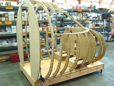
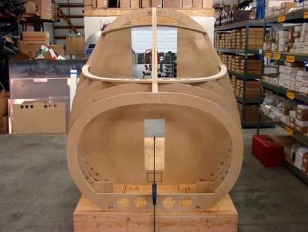
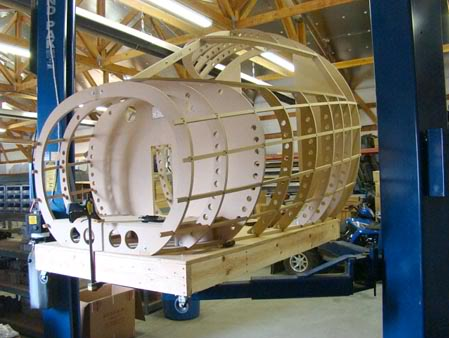
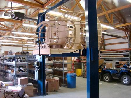
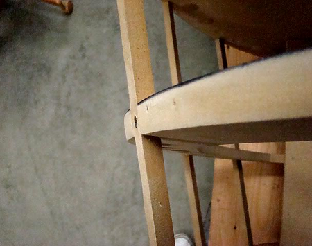
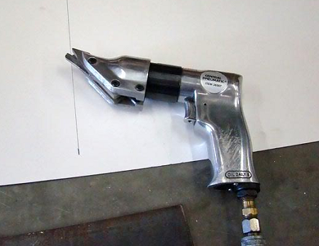
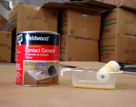
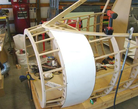
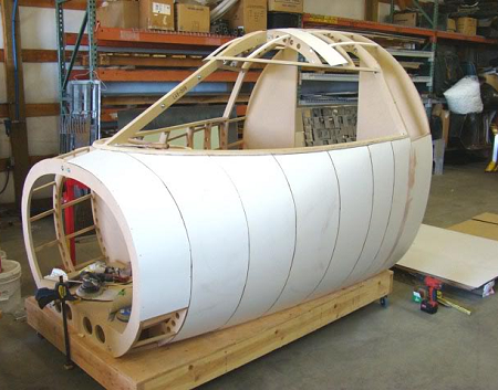
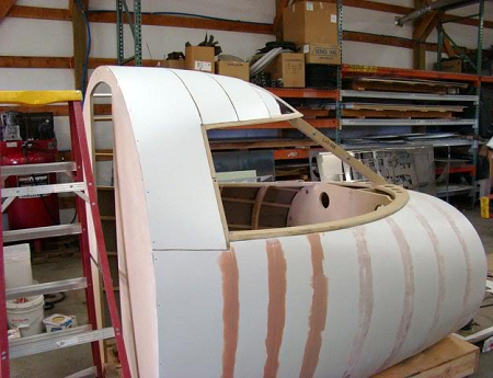
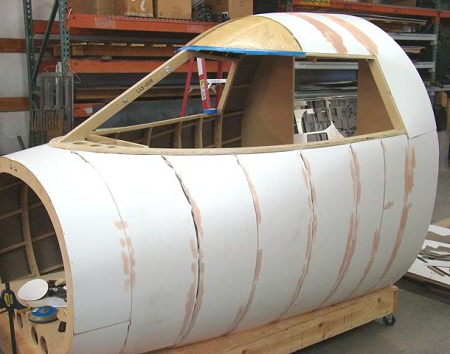
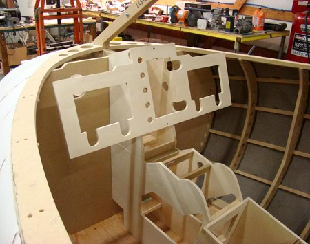
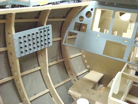
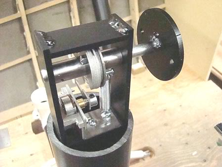
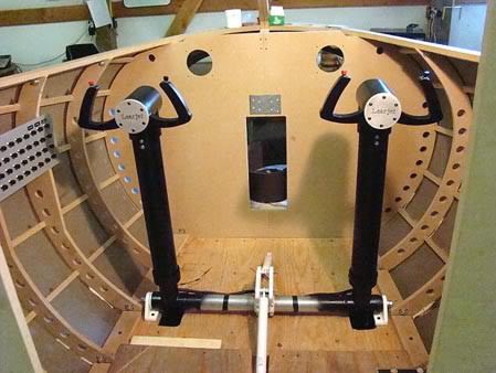
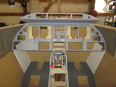
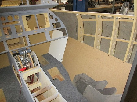
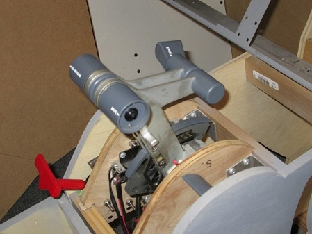
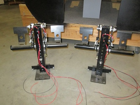
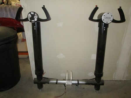
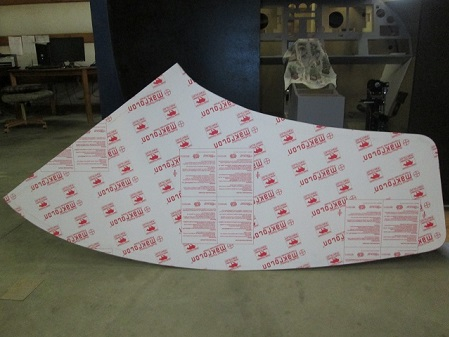
(Original thread started on 03-13-09 by Tom Goldberg) I somewhat introduced myself on one of these pages but thought I would do it again. My name is Tom Goldberg, and I live just north of Spokane Washington in a small farm type community called Deer Park Washington. Our little airport is (KDEW). Anyway two days ago I received this big box of wood and as I began to assemble it I found out that it was actually a work of art created by my new friend Ron Rollo. Without hesitation, we quickly went to the lumber yard and bought the materials needed to make the base frame for the shell to sit on. Then yesterday we began to assemble our new shell,and with the help of Ron's excellent SAM manual, every screw fell right into place, that is a sign of excellent quality and craftsmanship that is very rare these days. It is hard to find someone that puts 100% effort into making something the best way they can. I want to thank both Ron Rollo and Eric Tomlin for making this possible! We put in a lot of bolts, in Ron's process called bolting. And for anybody new who does not know what that means, it is a way to either fix the small splits you may get in the MDF board which can occur from drilling through the edge of the board or over tightening the screws. Luckily for me I only had a couple of these splits occur but we completely bolted all of the upper and lower ribs of the airframe, the bolting will pull the split closed,and also make sure that down the road you will not have any splits occur due to moving or twisting the airframe around. A very good idea by Ron. A suggestion that I might make to anyone that wants to build this airframe is you for sure want a cordless drill because there is a lot of screws, however, I would suggest you run the screws down almost tight with the drill and then grab the good old hand type screwdriver for your final tighten. I think until something better comes along the MDF material is a good choice and Ron came up with a solution to a small problem. The next thing we did was to install all of the small square brackets that help to tie the port and starboard sides together. After that we installed the support blocks for the avionics floor to rest on then installed the floor itself where you will house your computers etc... Then after that the fun really begins, the notching and installation of the lateral stringers, I think I got three done near the end of the day so I only have a 107 more to do. So I'm sure I wont be posting any pics for a few days. We have spent the last few days working on notching and installing the lateral stringers. We have both of the sides done, now on to work on the top side finishing them out. Lets see Ron, I counted 96 so far, were getting there. And by the way, we did have our L45 airborne for the first time yesterday, at one point we reached an altitude of six feet! Actually I put it on my lift to do the bottom stringers, much better than laying on the ground on concrete: (Posted by Ron Rollo on 03-19-09) Wow Tom! These are the coolest pictures of the shell to date! I should have known you would do something like this. (I know all about crawling around on the floor getting to the lower lateral strips, not fun, but it must be done.) It surely looks like you are having fun which is what it is all about. Keep up the great work! (Posted by Shane Barnes on 03-20-09) Tom has beat us to a motion flight simulator! Cool looking sitting up in the air on the lift, just imagine if it had the skin on. Ron's creation looks right at home in the air! (Posted by Tom Goldberg on 05-29-09) Eric asked for some details as to how I skinned my bird so here you go, hope it helps. I will lay this out from the beginning steps. 1. First make sure that all of the ribs have been sanded to have the correct angles with the laterals. You don't have to sand clear down to be flush with the laterals. In the case that the laterals are a little to deep in the notches like some of mine were. Ron has dimensions of all the ribs correctly so we will use the ribs for the contour of the skin not the laterals. For this step, I used a hand grinder with a 40 grit pad it made quick work of it. Then I used a hand sander to finish it: 2. Here is a list of some things you will need. The stuff I used to cover with is counter top laminate I bought at Home Depot. It's just a plain white smooth finish about 1/32" thick. It comes in 4'x8' sheets and I payed about $45 a sheet for it. Another thing you might want to get is a pneumatic sheet metal cutter. You can buy them cheap at Harbor Freight and they make quick work of cutting this material. Trying to use scissors or a knife is very difficult! You will also need to buy some contact cement. The stuff I use is the Weldwood original contact cement and get yourself a little tiny roller like you see in the picture. You will also want to get some super glue and some five minute epoxy to glue inside to the laterals later. You will also want to get some short wood screws with washer heads: 3. You want to start from the back of the shell and work your way forward. You will cover in panels, one panel will be the width of two ribs or as I call it one bay. You will cut the panels cutting across the four foot width of the sheet not the eight foot length of the sheet due to the way the grain on the back runs the eight foot length of the sheet. I hope that makes sense. 4. When you measure across the ribs, make sure you leave some extra material extending beyond the ribs on both sides. You then slip the first panel on, starting from the bottom and roll it up tight with your hands over the ribs keeping it tight until you reach the top. You don't want any gaps here. When you reach the top, hold it in place and drill a hole through the material and the rib. Put a screw in to hold it then move to the other side and do the same. I went back and forth between the ribs as I put the screws down the side. And as you progress down the side make sure you keep the material tight as you go to follow the contour. This gets a little more interesting as you progress forward and begin to run into the compound curves: 5. Okay, next get a ball point pen and use it to make your cut lines marking from the inside of the shell. Make your lines on the outside edges of the ribs and for the first panel make a cut line at the top edge of the top lateral. Unscrew your panel. The cut line that you made at the back of the shell will be cut on that line. The other cut lines will need to be measured in 7/16" from were you drew them. This will allow the gaps that we need between panels. once you do that go back and test fit it. You can screw it back on if you like or just hold it into place if you can but don't do any gluing yet. Another thing you should do is mark the panel so you know which end is up and which number panel it is. I just wrote on the inside of the panel (top) and if you start with the starboard, I wrote (S1). Do this for each panel along the way. Don't worry if your cuts aren't perfect as we will fill the seams with Bondo. But the main thing is make sure you have at least an 1/8" gap between the panels. After you have checked your fit, take the panel back off and set it aside so you can do the next panel. 6. Now on to panel #2. This panel and the rest going forward until the last panel will be cut differently. Make your cut lines on the outside edges of the ribs and draw the top cut line under the bottom edge of the lower windscreen. Then you will measure 7/16" on both sides. The mark you made for the lower windscreen will be cut at that mark. You will continue doing the same thing moving towards the front. Once you get near the front you will want to make sure you have enough material to cover the whole bay as the compound curves start to come into play and as you come up and around the curves, it will need more material to cover it. Once you have all of your panels cut for one side, I failed to mention you will need to get some balsa wood strips to go under the lower windscreen. You will need some 1/2" by 1/2" by whatever length you can get. These will be super-glued under the lower windscreen to glue the top edge of the panels to. Starting from the back, cut strips to fit between the bays, super-glue them in place once you get towards the front. You will want to leave some edge sticking out so you can fold the material down on top of it. Sand the balsa to match your curves and angles. You will see how it goes once you start doing it: (Original thread started on 03-13-09 by Tom Goldberg) I somewhat introduced myself on one of these pages but thought I would do it again. My name is Tom Goldberg, and I live just north of Spokane Washington in a small farm type community called Deer Park Washington. Our little airport is (KDEW). Anyway two days ago I received this big box of wood and as I began to assemble it I found out that it was actually a work of art created by my new friend Ron Rollo. Without hesitation, we quickly went to the lumber yard and bought the materials needed to make the base frame for the shell to sit on. Then yesterday we began to assemble our new shell,and with the help of Ron's excellent SAM manual, every screw fell right into place, that is a sign of excellent quality and craftsmanship that is very rare these days. It is hard to find someone that puts 100% effort into making something the best way they can. I want to thank both Ron Rollo and Eric Tomlin for making this possible! We put in a lot of bolts, in Ron's process called bolting. And for anybody new who does not know what that means, it is a way to either fix the small splits you may get in the MDF board which can occur from drilling through the edge of the board or over tightening the screws. Luckily for me I only had a couple of these splits occur but we completely bolted all of the upper and lower ribs of the airframe, the bolting will pull the split closed,and also make sure that down the road you will not have any splits occur due to moving or twisting the airframe around. A very good idea by Ron. A suggestion that I might make to anyone that wants to build this airframe is you for sure want a cordless drill because there is a lot of screws, however, I would suggest you run the screws down almost tight with the drill and then grab the good old hand type screwdriver for your final tighten. I think until something better comes along the MDF material is a good choice and Ron came up with a solution to a small problem. The next thing we did was to install all of the small square brackets that help to tie the port and starboard sides together. After that we installed the support blocks for the avionics floor to rest on then installed the floor itself where you will house your computers etc... Then after that the fun really begins, the notching and installation of the lateral stringers, I think I got three done near the end of the day so I only have a 107 more to do. So I'm sure I wont be posting any pics for a few days. We have spent the last few days working on notching and installing the lateral stringers. We have both of the sides done, now on to work on the top side finishing them out. Lets see Ron, I counted 96 so far, were getting there. And by the way, we did have our L45 airborne for the first time yesterday, at one point we reached an altitude of six feet! Actually I put it on my lift to do the bottom stringers, much better than laying on the ground on concrete: (Posted by Ron Rollo on 03-19-09) Wow Tom! These are the coolest pictures of the shell to date! I should have known you would do something like this. (I know all about crawling around on the floor getting to the lower lateral strips, not fun, but it must be done.) It surely looks like you are having fun which is what it is all about. Keep up the great work! (Posted by Shane Barnes on 03-20-09) Tom has beat us to a motion flight simulator! Cool looking sitting up in the air on the lift, just imagine if it had the skin on. Ron's creation looks right at home in the air! (Posted by Tom Goldberg on 05-29-09) Eric asked for some details as to how I skinned my bird so here you go, hope it helps. I will lay this out from the beginning steps. 1. First make sure that all of the ribs have been sanded to have the correct angles with the laterals. You don't have to sand clear down to be flush with the laterals. In the case that the laterals are a little to deep in the notches like some of mine were. Ron has dimensions of all the ribs correctly so we will use the ribs for the contour of the skin not the laterals. For this step, I used a hand grinder with a 40 grit pad it made quick work of it. Then I used a hand sander to finish it: 2. Here is a list of some things you will need. The stuff I used to cover with is counter top laminate I bought at Home Depot. It's just a plain white smooth finish about 1/32" thick. It comes in 4'x8' sheets and I payed about $45 a sheet for it. Another thing you might want to get is a pneumatic sheet metal cutter. You can buy them cheap at Harbor Freight and they make quick work of cutting this material. Trying to use scissors or a knife is very difficult! You will also need to buy some contact cement. The stuff I use is the Weldwood original contact cement and get yourself a little tiny roller like you see in the picture. You will also want to get some super glue and some five minute epoxy to glue inside to the laterals later. You will also want to get some short wood screws with washer heads: 3. You want to start from the back of the shell and work your way forward. You will cover in panels, one panel will be the width of two ribs or as I call it one bay. You will cut the panels cutting across the four foot width of the sheet not the eight foot length of the sheet due to the way the grain on the back runs the eight foot length of the sheet. I hope that makes sense. 4. When you measure across the ribs, make sure you leave some extra material extending beyond the ribs on both sides. You then slip the first panel on, starting from the bottom and roll it up tight with your hands over the ribs keeping it tight until you reach the top. You don't want any gaps here. When you reach the top, hold it in place and drill a hole through the material and the rib. Put a screw in to hold it then move to the other side and do the same. I went back and forth between the ribs as I put the screws down the side. And as you progress down the side make sure you keep the material tight as you go to follow the contour. This gets a little more interesting as you progress forward and begin to run into the compound curves: 5. Okay, next get a ball point pen and use it to make your cut lines marking from the inside of the shell. Make your lines on the outside edges of the ribs and for the first panel make a cut line at the top edge of the top lateral. Unscrew your panel. The cut line that you made at the back of the shell will be cut on that line. The other cut lines will need to be measured in 7/16" from were you drew them. This will allow the gaps that we need between panels. once you do that go back and test fit it. You can screw it back on if you like or just hold it into place if you can but don't do any gluing yet. Another thing you should do is mark the panel so you know which end is up and which number panel it is. I just wrote on the inside of the panel (top) and if you start with the starboard, I wrote (S1). Do this for each panel along the way. Don't worry if your cuts aren't perfect as we will fill the seams with Bondo. But the main thing is make sure you have at least an 1/8" gap between the panels. After you have checked your fit, take the panel back off and set it aside so you can do the next panel. 6. Now on to panel #2. This panel and the rest going forward until the last panel will be cut differently. Make your cut lines on the outside edges of the ribs and draw the top cut line under the bottom edge of the lower windscreen. Then you will measure 7/16" on both sides. The mark you made for the lower windscreen will be cut at that mark. You will continue doing the same thing moving towards the front. Once you get near the front you will want to make sure you have enough material to cover the whole bay as the compound curves start to come into play and as you come up and around the curves, it will need more material to cover it. Once you have all of your panels cut for one side, I failed to mention you will need to get some balsa wood strips to go under the lower windscreen. You will need some 1/2" by 1/2" by whatever length you can get. These will be super-glued under the lower windscreen to glue the top edge of the panels to. Starting from the back, cut strips to fit between the bays, super-glue them in place once you get towards the front. You will want to leave some edge sticking out so you can fold the material down on top of it. Sand the balsa to match your curves and angles. You will see how it goes once you start doing it: CONTINUATION: 7. Okay, now on to gluing the panels on. Starting from the back using your roller, roll the back side of the panel edges, top and sides. You don't need to do the bottom edge. Then roll some contact cement on the two ribs you are doing and on the balsa wood strip. You will want to go back and re-coat each piece again after about 5 minutes. Then wait 10 minutes or so for the glue to get tacky. Then you will apply the panel to the ribs. Starting from the top, line the panel up as best as you can. Press the top part into place and begin to roll the panel tight down the sides with you fingers as you go. There is no need to screw or clamp this into place once this glue grabs it stays in place. By chance you screw up with your alignment or your not happy with the fit you can pull the panel back off carefully but don't wait to long before you do it. This is probably the hardest part of the job so take your time here. Once this glue sets up, you will never get these panels off again. But don't let this scare you, its not that hard: After we completed the skin on both sides and smoothed on the Bondo, we are now ready to do the overhead sections. Starting at the back of the shell bay 1, we glue on 2 pieces of 1/2" by 1/2" balsa strips just on the first 2 vertical bays just to the upper windscreen. They will be used to glue the skin to. This leaves the vertical rib open at the back of the upper and lower windscreen to attach the windshield to. Also notice that sheet at the top of the upper windscreen extends out 7/16" so that it will run in the center of the rib to the top of the overhead. You will also need balsa strips on the next 2 forward bays. You don't actually need them on the bay at the very front: I realized when I got to the very front bay that I wasn't going to be able to add a sheet in the usual way as there is no way to make this stuff bend in 4 different directions. So thanks to Ron's brilliant mind, I used his technique using the foam in this area. You can see in the picture we just added a cross brace 1 1/2" wide aluminum strip running under the overhead lateral and 2 separate pieces running parallel under the lateral. Those pieces were screwed from underneath then cut out 4 patch sections and glued them in place using 5 minute epoxy. Also, there is balsa strips glued to the sides of the ribs under the patch pieces: After your done with that, go back and install the first 3 sheets from back to front in the usual way: Then lay your fiberglass cloth over the section and smooth it out. Then I used superglue to glue around the perimeters of each front section. When dry, cut the remaining waste cloth away. Use some painters tape around the upper windscreen. Go ahead and lay your fiberglass on. I used 2 good coats. Then peel off your painters tape: (Posted by Shane Barnes on 05-29-09) Well there is more than one way to skin a cat! I mean Lear! Ok, Ok, bad joke. I just finished applying foam to 007 so I'll blame it on the fumes. Really nice looking Tom, that will be another good option for covering the shell, looks like you are using Bondo to smooth out the seams. That will look really good when you have primed and sanded everything smooth. Great to see update photos of 006! Hope you are having as much fun with the project as I am! (Posted by Tom Goldberg on 05-07-10) We built the TQ assembly, center pedestal, MIP backer and the support tower. Things went pretty quick. I also cut out aluminum templates for each of these items so I could just trace around them on the wood: This is my mock circuit breaker panel. As I really didn't have any intention on building a full scale full functioning circuit breaker panel but I thought it would be nice to at least have something down in that area so we found some push buttons that somewhat looks like circuit breakers and it will be a full functioning panel but can be used for functions that the real airplane wouldn't have. For instance you ran out of beer or have to hit the head you simply push the pause button. You could bring up your ATC window, you could look at your GPS, basically things like that. These are simple momentary off-on push buttons that will be wired to a 32 button USB plug and play card: Here is what we have been working on the last few days. This is a drop in yoke unit I designed somewhat similar to Scott's 737 setup, but with a few changes. The pot unit is right up top and is rotated by the top steering shaft and clevis setup. We decided to do it this way much simpler then using gears and pulleys making it easy to get at and the whole unit can be unbolted and pulled out the top for easy access: The yoke and columns setup is completed and functioning well. If you haven't done this yet you are in for a treat. The wiring for the pots and switches all comes out near the bottom front of the columns. Anyway, I'm glad to have this done. We will now begin designing and building the seat frames and seats. This should prove to be interesting. We will keep you up to date on that as we progress: I may put some trim switches down on the center console somewhere. I have also been looking at the seats thread which is where I am getting information to build the seat frames and seats. I am still working this one out in my head as all we really have to go by for the framework is pictures but I've got some ideas.
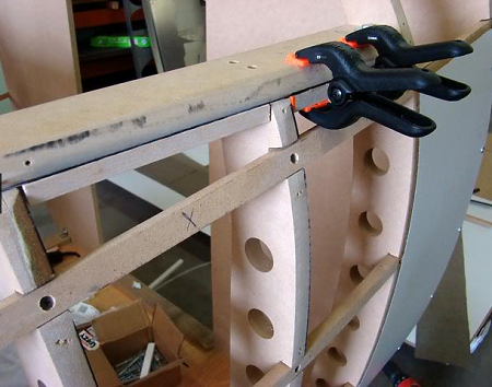
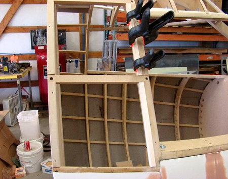
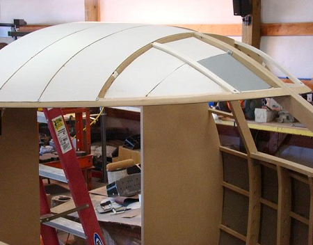
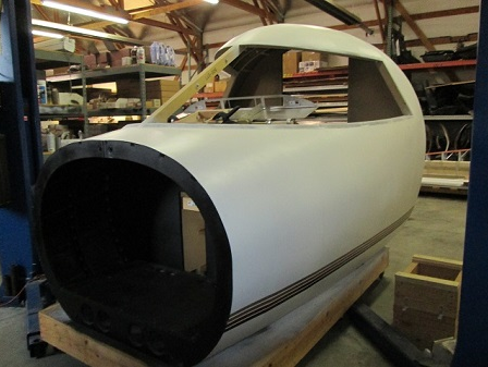
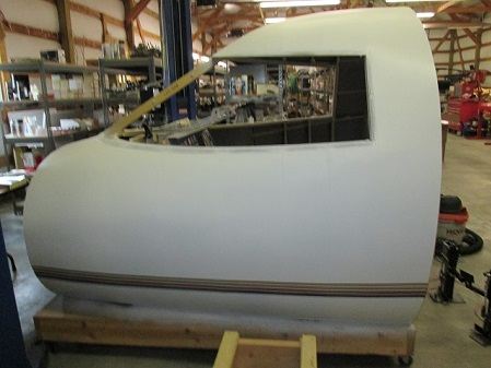
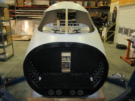
CONTINUATION: 7. Okay, now on to gluing the panels on. Starting from the back using your roller, roll the back side of the panel edges, top and sides. You don't need to do the bottom edge. Then roll some contact cement on the two ribs you are doing and on the balsa wood strip. You will want to go back and re-coat each piece again after about 5 minutes. Then wait 10 minutes or so for the glue to get tacky. Then you will apply the panel to the ribs. Starting from the top, line the panel up as best as you can. Press the top part into place and begin to roll the panel tight down the sides with you fingers as you go. There is no need to screw or clamp this into place once this glue grabs it stays in place. By chance you screw up with your alignment or your not happy with the fit you can pull the panel back off carefully but don't wait to long before you do it. This is probably the hardest part of the job so take your time here. Once this glue sets up, you will never get these panels off again. But don't let this scare you, its not that hard: After we completed the skin on both sides and smoothed on the Bondo, we are now ready to do the overhead sections. Starting at the back of the shell bay 1, we glue on 2 pieces of 1/2" by 1/2" balsa strips just on the first 2 vertical bays just to the upper windscreen. They will be used to glue the skin to. This leaves the vertical rib open at the back of the upper and lower windscreen to attach the windshield to. Also notice that sheet at the top of the upper windscreen extends out 7/16" so that it will run in the center of the rib to the top of the overhead. You will also need balsa strips on the next 2 forward bays. You don't actually need them on the bay at the very front: I realized when I got to the very front bay that I wasn't going to be able to add a sheet in the usual way as there is no way to make this stuff bend in 4 different directions. So thanks to Ron's brilliant mind, I used his technique using the foam in this area. You can see in the picture we just added a cross brace 1 1/2" wide aluminum strip running under the overhead lateral and 2 separate pieces running parallel under the lateral. Those pieces were screwed from underneath then cut out 4 patch sections and glued them in place using 5 minute epoxy. Also, there is balsa strips glued to the sides of the ribs under the patch pieces: After your done with that, go back and install the first 3 sheets from back to front in the usual way: Then lay your fiberglass cloth over the section and smooth it out. Then I used superglue to glue around the perimeters of each front section. When dry, cut the remaining waste cloth away. Use some painters tape around the upper windscreen. Go ahead and lay your fiberglass on. I used 2 good coats. Then peel off your painters tape: (Posted by Shane Barnes on 05-29-09) Well there is more than one way to skin a cat! I mean Lear! Ok, Ok, bad joke. I just finished applying foam to 007 so I'll blame it on the fumes. Really nice looking Tom, that will be another good option for covering the shell, looks like you are using Bondo to smooth out the seams. That will look really good when you have primed and sanded everything smooth. Great to see update photos of 006! Hope you are having as much fun with the project as I am! (Posted by Tom Goldberg on 05-07-10) We built the TQ assembly, center pedestal, MIP backer and the support tower. Things went pretty quick. I also cut out aluminum templates for each of these items so I could just trace around them on the wood: This is my mock circuit breaker panel. As I really didn't have any intention on building a full scale full functioning circuit breaker panel but I thought it would be nice to at least have something down in that area so we found some push buttons that somewhat looks like circuit breakers and it will be a full functioning panel but can be used for functions that the real airplane wouldn't have. For instance you ran out of beer or have to hit the head you simply push the pause button. You could bring up your ATC window, you could look at your GPS, basically things like that. These are simple momentary off-on push buttons that will be wired to a 32 button USB plug and play card: Here is what we have been working on the last few days. This is a drop in yoke unit I designed somewhat similar to Scott's 737 setup, but with a few changes. The pot unit is right up top and is rotated by the top steering shaft and clevis setup. We decided to do it this way much simpler then using gears and pulleys making it easy to get at and the whole unit can be unbolted and pulled out the top for easy access: The yoke and columns setup is completed and functioning well. If you haven't done this yet you are in for a treat. The wiring for the pots and switches all comes out near the bottom front of the columns. Anyway, I'm glad to have this done. We will now begin designing and building the seat frames and seats. This should prove to be interesting. We will keep you up to date on that as we progress: I may put some trim switches down on the center console somewhere. I have also been looking at the seats thread which is where I am getting information to build the seat frames and seats. I am still working this one out in my head as all we really have to go by for the framework is pictures but I've got some ideas.
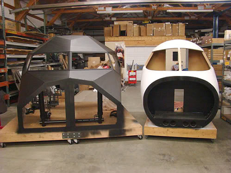
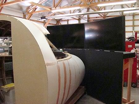
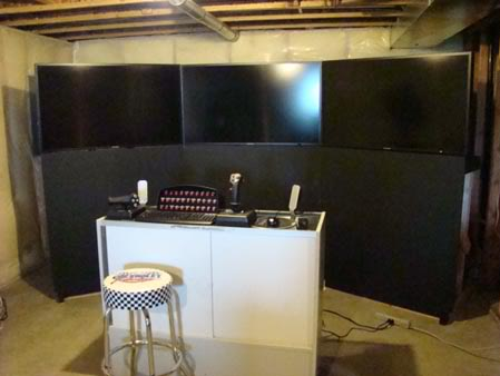
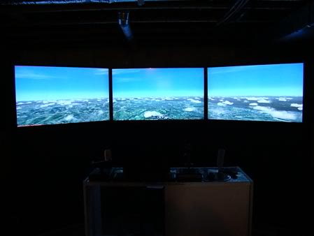
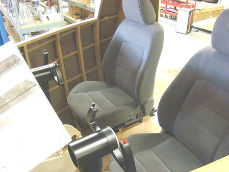
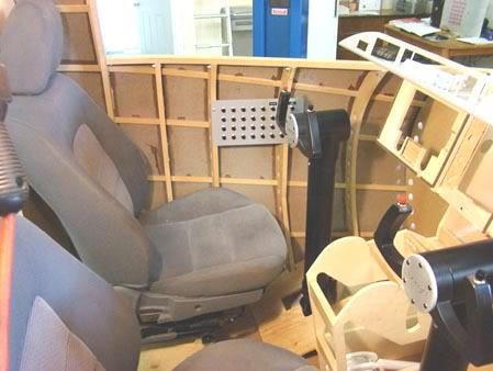
Thought I would take this picture as I may not have another opportunity to do this do to room constraints. Here is Big Boy, my 737 sim shell and Little Boy, the Lear45 shell side by side: (Posted by Ron Rollo on 05-08-10) Hey Tom, just so you know, one of the backer panels I made for you is called the "TRIM switch panel". It is located on the center pedestal. This panel has a PRI and a SEC selection which toggles you back and further from the primary trim switches which are on your yokes to the secondary trim switch which is located on this TRIM panel. You can read about how it works in that Flight Safety CD that I gave you. If nothing else, you can model the TRIM switch on the center pedestal panel and have it wired up for future expansion to your yokes. Eventually, you WILL want to have trim switches on your control wheels one way or the other. Look into momentary rocker switches for your pitch trim. Primarily, you will need pitch trim, roll is not as critical. These are some photos of Tom's LCD visual system: We are finally at the point where we are installing seats into the shell. At first, we were going to design the seats just like the real thing, however, after looking at how they were designed and the complexity of making all of the mechanisms to make the seats go up and down, back and forth etc, we decided not to go that route. It was way more work than I really wanted to do. So we scoured our local import wrecking yard and after looking through hundreds of different cars we found a set of seats that somewhat simulate the appearance of the Lear seats. They also have a mechanical functions on them to make the seats go up and down, forwards and backwards and recline. They are out of a 2003 Mazda 6. The only thing is they are a bit wider then the Lear seats. I could find no seats that were 17" wide. Most everything is around 20", but that is okay as they still fit in the shell but rather tight near the center console area may have to be modified. The seat length is the same and also the seat back height is the same. Now if any of you have not yet installed a seat and the center console together, you are in for a surprise when trying to get into your seat. It is difficult enough just to get into the seat trying to get out of the seat is another story. This is why I will be taking contortionist lessons this weekend to see if I can wrap my legs around the back of my head and simply roll out of the cockpit on to the floor. I sure hope my house never catches on fire while I am in my sim. I am afraid they would find the burnt wreckage with me still inside. Now on a serious note, there is no doubt that I will be making a functional assist handle to help get out of this thing. Ron's shell is quite strong in design, however, I don't want to take any chances pulling the roof in on my head so we will be making some 1/8" metal strips that are attached on both sides and follow the length of the roof ribs inside to add strength to the MDF ribbing. I will put up pics of that when we get to it but for now we have to learn how to best get in and out of this thing before we go to much further. Here are some pics of the seats somewhat installed but it gives you an idea of what it looks like. I will find some nice seat covers later, but the center console will have to be narrowed and shortened up. I think we can leave the back wall intact still a bit of a challenge to get in this thing, but I don't want to struggle every time I have to get in and out and also I would like to have my dad fly with me on occasion and I don't think he is much in to doing acrobatics anymore these days: Thought I would take this picture as I may not have another opportunity to do this do to room constraints. Here is Big Boy, my 737 sim shell and Little Boy, the Lear45 shell side by side: (Posted by Ron Rollo on 05-08-10) Hey Tom, just so you know, one of the backer panels I made for you is called the "TRIM switch panel". It is located on the center pedestal. This panel has a PRI and a SEC selection which toggles you back and further from the primary trim switches which are on your yokes to the secondary trim switch which is located on this TRIM panel. You can read about how it works in that Flight Safety CD that I gave you. If nothing else, you can model the TRIM switch on the center pedestal panel and have it wired up for future expansion to your yokes. Eventually, you WILL want to have trim switches on your control wheels one way or the other. Look into momentary rocker switches for your pitch trim. Primarily, you will need pitch trim, roll is not as critical. These are some photos of Tom's LCD visual system: We are finally at the point where we are installing seats into the shell. At first, we were going to design the seats just like the real thing, however, after looking at how they were designed and the complexity of making all of the mechanisms to make the seats go up and down, back and forth etc, we decided not to go that route. It was way more work than I really wanted to do. So we scoured our local import wrecking yard and after looking through hundreds of different cars we found a set of seats that somewhat simulate the appearance of the Lear seats. They also have a mechanical functions on them to make the seats go up and down, forwards and backwards and recline. They are out of a 2003 Mazda 6. The only thing is they are a bit wider then the Lear seats. I could find no seats that were 17" wide. Most everything is around 20", but that is okay as they still fit in the shell but rather tight near the center console area may have to be modified. The seat length is the same and also the seat back height is the same. Now if any of you have not yet installed a seat and the center console together, you are in for a surprise when trying to get into your seat. It is difficult enough just to get into the seat trying to get out of the seat is another story. This is why I will be taking contortionist lessons this weekend to see if I can wrap my legs around the back of my head and simply roll out of the cockpit on to the floor. I sure hope my house never catches on fire while I am in my sim. I am afraid they would find the burnt wreckage with me still inside. Now on a serious note, there is no doubt that I will be making a functional assist handle to help get out of this thing. Ron's shell is quite strong in design, however, I don't want to take any chances pulling the roof in on my head so we will be making some 1/8" metal strips that are attached on both sides and follow the length of the roof ribs inside to add strength to the MDF ribbing. I will put up pics of that when we get to it but for now we have to learn how to best get in and out of this thing before we go to much further. Here are some pics of the seats somewhat installed but it gives you an idea of what it looks like. I will find some nice seat covers later, but the center console will have to be narrowed and shortened up. I think we can leave the back wall intact still a bit of a challenge to get in this thing, but I don't want to struggle every time I have to get in and out and also I would like to have my dad fly with me on occasion and I don't think he is much in to doing acrobatics anymore these days: Here are a few photos of the overall project and the completed shell: NOTE: This project is FOR SALE! Contact Tom Goldberg at tbtransmission@gmail.com or Ron Rollo at ronjonrollo@yahoo.com for more details. Here are a few photos of the overall project and the completed shell: NOTE: This project is FOR SALE! Contact Tom Goldberg at tbtransmission@gmail.com or Ron Rollo at ronjonrollo@yahoo.com for more details.Astron Lear45 L45-006 Project (Retired!!)
![]()
![]()
![]()
![]()
2017-10-10