


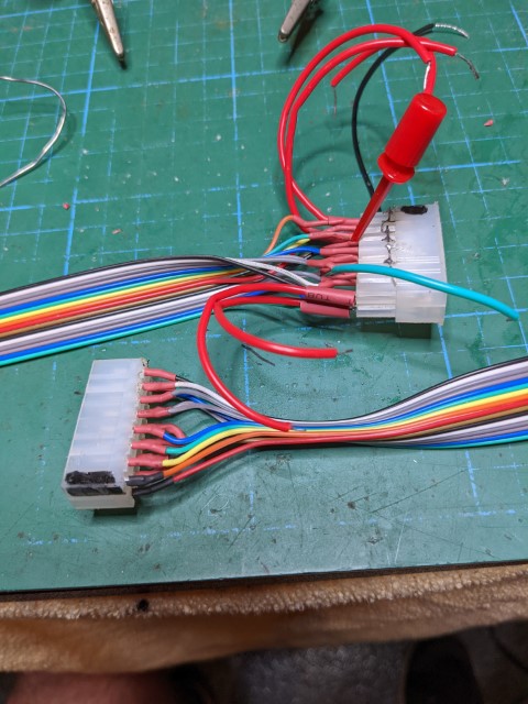
Jet45 v2 requires all input devices be connected to specific pins on the Arduino board. As I am converting my sim from the nine pin SysBoards, all my panels are already wired to an in-line connector (D-Sub) with the wire length usually about 6” to 8”. This is to make it easy to remove and refit them if maintenance is required. So I have to map the D-Sub pins and create an interconnecting wiring harness from this D-sub connector to an in-line TE connector which plugs into the header on Rons Arduino PCB’s. I have created some tools to make this easier for me, and I thought I would share them with you. Where I have used D-Sub you can use whatever style of connector you have on your harness. The principle is the same. Tool 1: Switch pin identify Tool 2: LED pin identify Tool 3: Whole harness check Here is a sketch of the entire harness as I am creating it: If you are not using an interconnect cable but instead going direct from the panel to the PCB connector, skip to Tool 3. Tools 1 & 2 are simply an inline plug/socket of the opposite gender (OG) to the Panel Connector (M) with LED’s (for Tool 2) or pins (for Tool 1) attached to the solder pins on the back of the plug (which is the front on this device). Tool 3 connects to the TE connector (F) at the PCB end of the Interconnect Cable with LEDs on the other end display pattern the same as the Jet45 AAS Systems Modules V2.xx document. NOTE: For TE connectors as they are a standard pattern smaller connectors fit into larger connectors so you will only need one version of Tools 1 & 2 - that being the largest size you are using. All smaller ones will fit. I have not designed Tools 1 & 2 for TE connectors, but if you refer to the how-to for Tool 3 you should be able to work it out. If your Panel Connector gender is the same as the interconnect cable (PCB end) you can use Tool 3 as Tool 1, or you could make a short gender changing cable. Recording results: The important part of using these tools is to record your findings. I took Ron’s brilliant Jet 45 AAS document and created tables to record and diagrams to create the required cables (pdf copy attached). To make construction of the interconnect cable easier to visualise I transcribed the panel connector pin numbers on to the graphic of the TE (F) connector at the PCB end. Here is a sample of how I used this document. TOOL 1: This tool is designed to create a circuit between power source, a switch (push-button/toggle/encoder), and an LED. A DB9 potentially has 8 circuits plus 1 common wire connecting all. In ordinary use this common wire is normally the -ve side of the circuit. For this tool I am using this common wire to feed +ve current to the 8 switches then to an LED and complete the circuit back to the -ve power source (you can reverse this if you wish, just make sure your LED polarity is correct). A basic sketch of the schematic: Finished Tool 1 for DB9/15/25: The switch doesn’t care which way the current is flowing, its either ON or OFF. Then when the switch is activated it completes the circuit along the signal wire attached to the individual pin in the plug you are investigating (Target plug) to an LED. Using your chosen numbering system for your plug you can push the attached buttons and note which pin lights up (for Normally-Off switches), or turns off (for Normally On switches). If you rather feed -ve into the common wire thats fine, just switch all references to -ve and +ve around from here on. To make the Switch Pin ID board: Take a piece of strip Proto-typing board (ie Mouser product #854-ST1 ), make sure it is 2 to 3 rows wider each side than the OG plug body (for electrical isolation). Cut a hole to fit the back of an OG plug in the board, align this hole in the same direction as the strips of copper on the board. Glue the plug in with the connection side ( the side that plugs into the target plug) on the same side as the copper strips - this is the back of this device. You now should have the solder pins of the plug on the front side of the device. Bend and trim the +ve leg on an LED so that it can be soldered onto the solder pin of the OG plug, whilst the -ve leg goes through a hole to the back side clear of any metal in the plug casing. Do this for each pin on the plug, spacing LED’s to suit and feeding the -ve leg through the same row of strip holes if possible. If you cant squeeze in enough LED’s in one row, put them wherever you want so long as its electrically isolated from the plug body. If you have 2 row plugs (like the D-Sub), feed the -ve legs into rows either side of the plug (see photo below). If you have more than 2 rows then you will need to put the LEDs in a separate board and run wires between the 2 boards. Which ever way you go always ensure the -ve par of the circit is electrically isolated from the plug body. Solder everything in place, use a short piece of black cable to link all -ve strips together, and a short piece of black cable to attach the -ve from your power supply. D etermine which pin is the common on the target plugs, then solder a short piece of red wire on the +ve leg of the matching pins LED (the bent leg soldered to the plug pin). If you have target plugs with variable common pins then solder a red wire to each of the associated LED +ve legs. In my photos you see 2 red wires attached to different LEDs, this is because i changed my standard practice of originally using pin5 to using pin1 as common. You only use one at any time, so having wires on several doesn’t matter. To use, plug the device into the Panel Connector plug. Connect negative lead from your power source to the -ve side of the device. Connect the +ve lead to the +ve leg on the pin that is the common wire pin of the target plug. All being good the LED that has the +ve connected will light up - this is your power on indicator. Then activating attached switches will turn on/off the associated pins’ LED. Using your numbering convention, note which pin activates which switch. Power On, common line pin 5: Switch on Pin 1 activated: Switch on Pin 2 activated: For the larger connectors (ie bigger than 12 pin) I recommend using a different looking LED every 5th one so it is easier to see which pin has been activated. Counting LED’s across a row of 15 or more introduces a site for potential error. You can see in the first photo that on the DB25 every 5th LED is pointing sideways, same LED as the others just angle differently enough to make counting simple. Jet45 v2 requires all input devices be connected to specific pins on the Arduino board. As I am converting my sim from the nine pin SysBoards, all my panels are already wired to an in-line connector (D-Sub) with the wire length usually about 6” to 8”. This is to make it easy to remove and refit them if maintenance is required. So I have to map the D-Sub pins and create an interconnecting wiring harness from this D-sub connector to an in-line TE connector which plugs into the header on Rons Arduino PCB’s. I have created some tools to make this easier for me, and I thought I would share them with you. Where I have used D-Sub you can use whatever style of connector you have on your harness. The principle is the same. Tool 1: Switch pin identify Tool 2: LED pin identify Tool 3: Whole harness check Here is a sketch of the entire harness as I am creating it: If you are not using an interconnect cable but instead going direct from the panel to the PCB connector, skip to Tool 3. Tools 1 & 2 are simply an inline plug/socket of the opposite gender (OG) to the Panel Connector (M) with LED’s (for Tool 2) or pins (for Tool 1) attached to the solder pins on the back of the plug (which is the front on this device). Tool 3 connects to the TE connector (F) at the PCB end of the Interconnect Cable with LEDs on the other end display pattern the same as the Jet45 AAS Systems Modules V2.xx document. NOTE: For TE connectors as they are a standard pattern smaller connectors fit into larger connectors so you will only need one version of Tools 1 & 2 - that being the largest size you are using. All smaller ones will fit. I have not designed Tools 1 & 2 for TE connectors, but if you refer to the how-to for Tool 3 you should be able to work it out. If your Panel Connector gender is the same as the interconnect cable (PCB end) you can use Tool 3 as Tool 1, or you could make a short gender changing cable. Recording results: The important part of using these tools is to record your findings. I took Ron’s brilliant Jet 45 AAS document and created tables to record and diagrams to create the required cables (pdf copy attached). To make construction of the interconnect cable easier to visualise I transcribed the panel connector pin numbers on to the graphic of the TE (F) connector at the PCB end. Here is a sample of how I used this document. TOOL 1: This tool is designed to create a circuit between power source, a switch (push-button/toggle/encoder), and an LED. A DB9 potentially has 8 circuits plus 1 common wire connecting all. In ordinary use this common wire is normally the -ve side of the circuit. For this tool I am using this common wire to feed +ve current to the 8 switches then to an LED and complete the circuit back to the -ve power source (you can reverse this if you wish, just make sure your LED polarity is correct). A basic sketch of the schematic: Finished Tool 1 for DB9/15/25: The switch doesn’t care which way the current is flowing, its either ON or OFF. Then when the switch is activated it completes the circuit along the signal wire attached to the individual pin in the plug you are investigating (Target plug) to an LED. Using your chosen numbering system for your plug you can push the attached buttons and note which pin lights up (for Normally-Off switches), or turns off (for Normally On switches). If you rather feed -ve into the common wire thats fine, just switch all references to -ve and +ve around from here on. To make the Switch Pin ID board: Take a piece of strip Proto-typing board (ie Mouser product #854-ST1 ), make sure it is 2 to 3 rows wider each side than the OG plug body (for electrical isolation). Cut a hole to fit the back of an OG plug in the board, align this hole in the same direction as the strips of copper on the board. Glue the plug in with the connection side ( the side that plugs into the target plug) on the same side as the copper strips - this is the back of this device. You now should have the solder pins of the plug on the front side of the device. Bend and trim the +ve leg on an LED so that it can be soldered onto the solder pin of the OG plug, whilst the -ve leg goes through a hole to the back side clear of any metal in the plug casing. Do this for each pin on the plug, spacing LED’s to suit and feeding the -ve leg through the same row of strip holes if possible. If you cant squeeze in enough LED’s in one row, put them wherever you want so long as its electrically isolated from the plug body. If you have 2 row plugs (like the D-Sub), feed the -ve legs into rows either side of the plug (see photo below). If you have more than 2 rows then you will need to put the LEDs in a separate board and run wires between the 2 boards. Which ever way you go always ensure the -ve par of the circit is electrically isolated from the plug body. Solder everything in place, use a short piece of black cable to link all -ve strips together, and a short piece of black cable to attach the -ve from your power supply. D etermine which pin is the common on the target plugs, then solder a short piece of red wire on the +ve leg of the matching pins LED (the bent leg soldered to the plug pin). If you have target plugs with variable common pins then solder a red wire to each of the associated LED +ve legs. In my photos you see 2 red wires attached to different LEDs, this is because i changed my standard practice of originally using pin5 to using pin1 as common. You only use one at any time, so having wires on several doesn’t matter. To use, plug the device into the Panel Connector plug. Connect negative lead from your power source to the -ve side of the device. Connect the +ve lead to the +ve leg on the pin that is the common wire pin of the target plug. All being good the LED that has the +ve connected will light up - this is your power on indicator. Then activating attached switches will turn on/off the associated pins’ LED. Using your numbering convention, note which pin activates which switch. Power On, common line pin 5: Switch on Pin 1 activated: Switch on Pin 2 activated: For the larger connectors (ie bigger than 12 pin) I recommend using a different looking LED every 5th one so it is easier to see which pin has been activated. Counting LED’s across a row of 15 or more introduces a site for potential error. You can see in the first photo that on the DB25 every 5th LED is pointing sideways, same LED as the others just angle differently enough to make counting simple. Tool 2 - The LED Pin ID Board: Here there are two options, Option 1: Plug in a clean opposite gender plug into the panel LED connector and apply power directly to the solder lugs on the back. Just remember this will be a mirror image of your numbering pattern. Option 2: I opted to remove the potential for confusion by creating an extension cable with the opposite gender (OG) plug on one end and on the other end a facsimile of the plug layout with pins conveniently spaced to allow clipping 3V power to without touching other pins. The wiring pattern for this extension cable is each end is a mirror image of the other. I used male header pin strips removing every 2nd pin to give the spacing required, and set it with staggered pins like the D-Sub connectors. Just make sure you get the orientation of the pins correct at each end. If like me you like visualisation aids to assist you with a mirror image try this - draw two plan views of your connector, add a line between to represent the mirror, number one side normally, then simply mirror to the other side. To use plug the cable into the target LED plug. Clip the -ve lead from your power supply to the common wire pin on the extension end of the cable. Touch/clip the +3V lead from the power supply to each other pin on the extension end and the connected LED on the panel will illuminate. Pin 3 powered, associated LED = XFR Left: Pin 1 powered, associated LED = SPD: Tool 2 - The LED Pin ID Board: Here there are two options, Option 1: Plug in a clean opposite gender plug into the panel LED connector and apply power directly to the solder lugs on the back. Just remember this will be a mirror image of your numbering pattern. Option 2: I opted to remove the potential for confusion by creating an extension cable with the opposite gender (OG) plug on one end and on the other end a facsimile of the plug layout with pins conveniently spaced to allow clipping 3V power to without touching other pins. The wiring pattern for this extension cable is each end is a mirror image of the other. I used male header pin strips removing every 2nd pin to give the spacing required, and set it with staggered pins like the D-Sub connectors. Just make sure you get the orientation of the pins correct at each end. If like me you like visualisation aids to assist you with a mirror image try this - draw two plan views of your connector, add a line between to represent the mirror, number one side normally, then simply mirror to the other side. To use plug the cable into the target LED plug. Clip the -ve lead from your power supply to the common wire pin on the extension end of the cable. Touch/clip the +3V lead from the power supply to each other pin on the extension end and the connected LED on the panel will illuminate. Pin 3 powered, associated LED = XFR Left: Pin 1 powered, associated LED = SPD: TOOL 3: (edited to change the wiring scheme between either end of this cable. It is not mirror image, but is more like a crossover. See image below) The purpose of this tool is to replicate the pin sequence as pictured in the jet 45 AAC systems manual so it simplifies confirmation/check that your pinouts are correct. The wiring is not mirror image. To help with the wiring connection between either end of this Tool here is another visualisation picture: Make the cable length long enough so that you can plug into the interconnect cable and position the LED indicating end somewhere easily visible from the cockpit. I used 1.8 m long cable so I can sit in front of the MIP and position the LED indicating end on top of the eyebrow panel directly in front of me. We only need one of these for all plug sizes, this being the largest required which in this case is the TE-16. All the smaller in-line female connectors will plug into the 16 header. First solder your wires to the TE 16 header block. If using heat shrink don’t shrink it on yet. Then take the TE 16 female case and drill through the step into the large cavity for each 16. Then take an LED and insert the positive lead through the female pin tube, and the negative lead through the hole you’ve just drilled. This will give you the negative wire coming out at the step in the case, and the positive wire protruding out the connector hole. Bend and wrap the -ve wires around the step in the case, then solder them together. Solder a short piece of black cable to this. Solder the other end of the wires from the header to the +ve LED leads. If using heat shrink at this end, leave ¼ inch of wire bare where it exits the connector housing to allow clipping leads to the wires. I discovered this need after heat shrinking my connections, hence the photo below does not show this gap. Check your connections are correctly oriented using a multimeter or line tester. If all good heat shrink both ends. Done! (Image of finished Tool, please see comment above re heat shrink): To use this tool: Notes: TOOL 3: (edited to change the wiring scheme between either end of this cable. It is not mirror image, but is more like a crossover. See image below) The purpose of this tool is to replicate the pin sequence as pictured in the jet 45 AAC systems manual so it simplifies confirmation/check that your pinouts are correct. The wiring is not mirror image. To help with the wiring connection between either end of this Tool here is another visualisation picture: Make the cable length long enough so that you can plug into the interconnect cable and position the LED indicating end somewhere easily visible from the cockpit. I used 1.8 m long cable so I can sit in front of the MIP and position the LED indicating end on top of the eyebrow panel directly in front of me. We only need one of these for all plug sizes, this being the largest required which in this case is the TE-16. All the smaller in-line female connectors will plug into the 16 header. First solder your wires to the TE 16 header block. If using heat shrink don’t shrink it on yet. Then take the TE 16 female case and drill through the step into the large cavity for each 16. Then take an LED and insert the positive lead through the female pin tube, and the negative lead through the hole you’ve just drilled. This will give you the negative wire coming out at the step in the case, and the positive wire protruding out the connector hole. Bend and wrap the -ve wires around the step in the case, then solder them together. Solder a short piece of black cable to this. Solder the other end of the wires from the header to the +ve LED leads. If using heat shrink at this end, leave ¼ inch of wire bare where it exits the connector housing to allow clipping leads to the wires. I discovered this need after heat shrinking my connections, hence the photo below does not show this gap. Check your connections are correctly oriented using a multimeter or line tester. If all good heat shrink both ends. Done! (Image of finished Tool, please see comment above re heat shrink): To use this tool: Notes: V2.0 PCB Wiring loom test tools
![]()


Connected: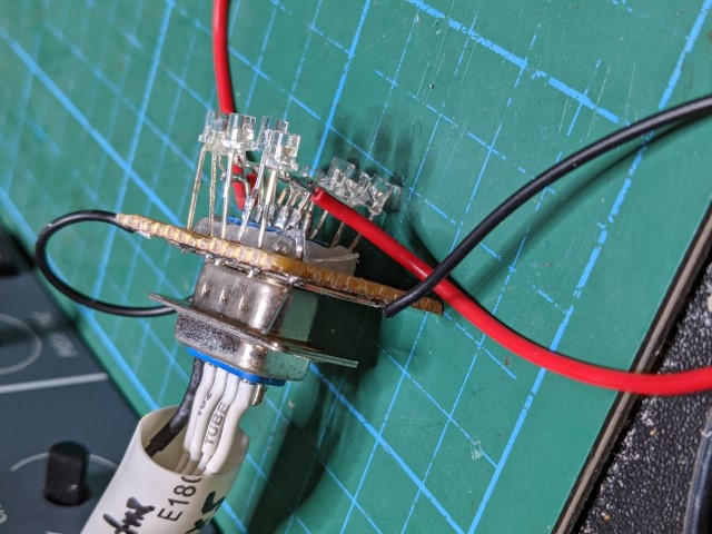


Connected:![]()


![]()


2017-10-10