


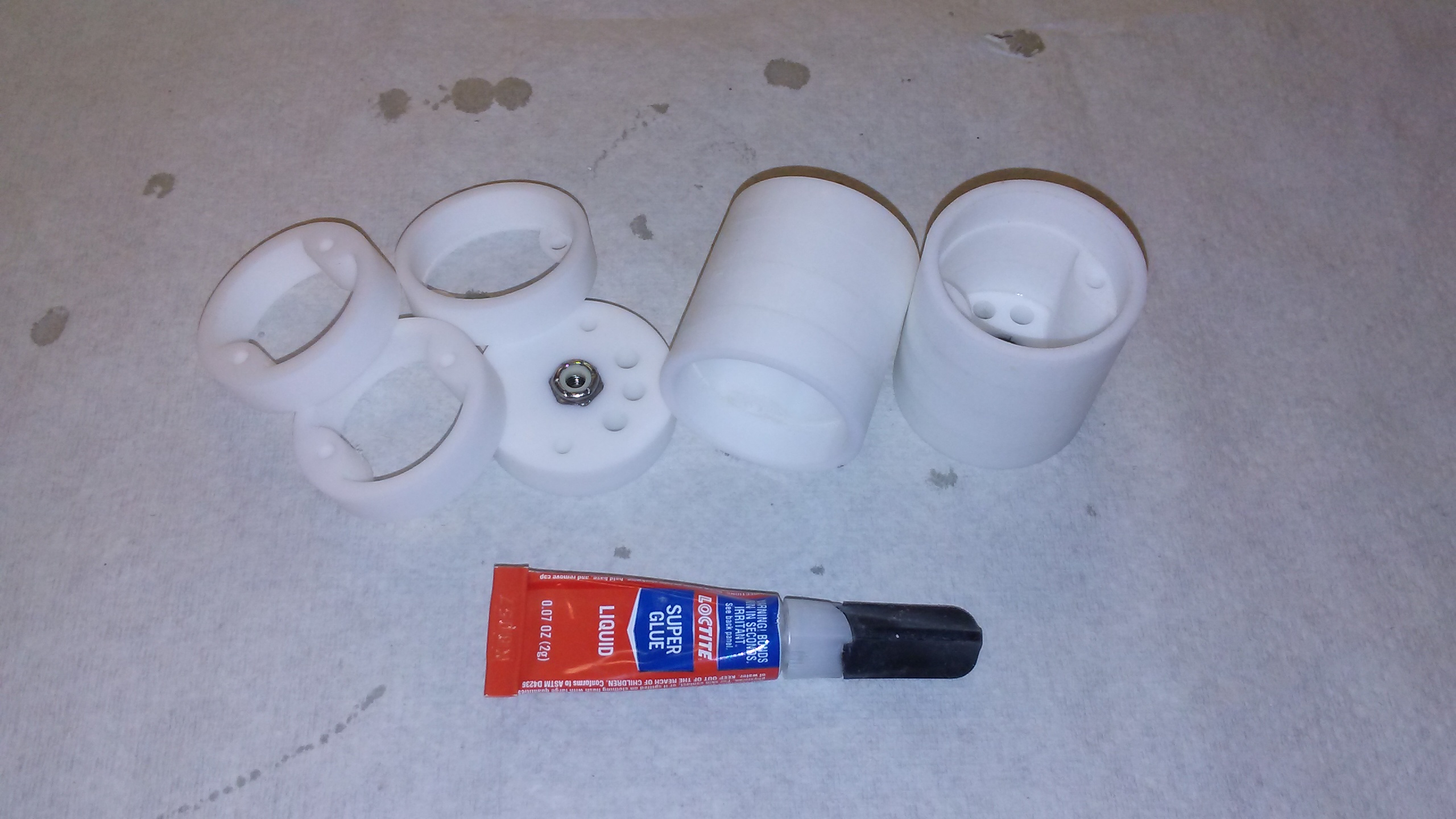
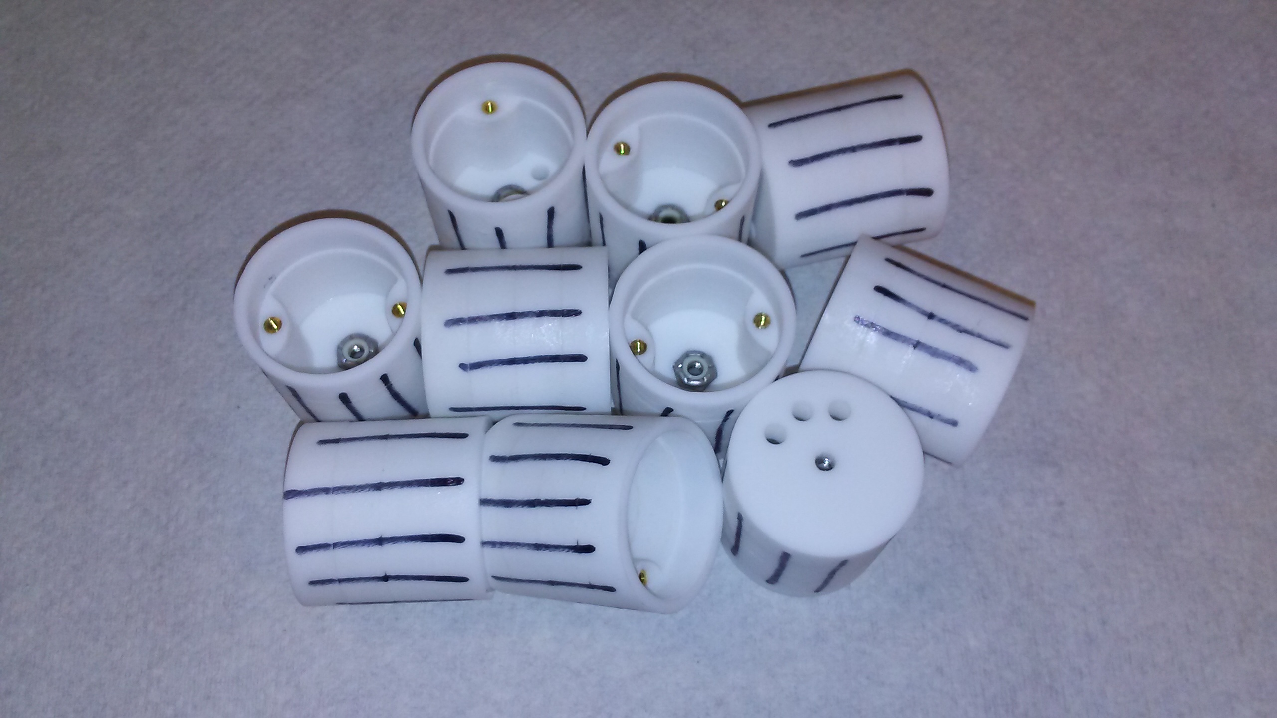
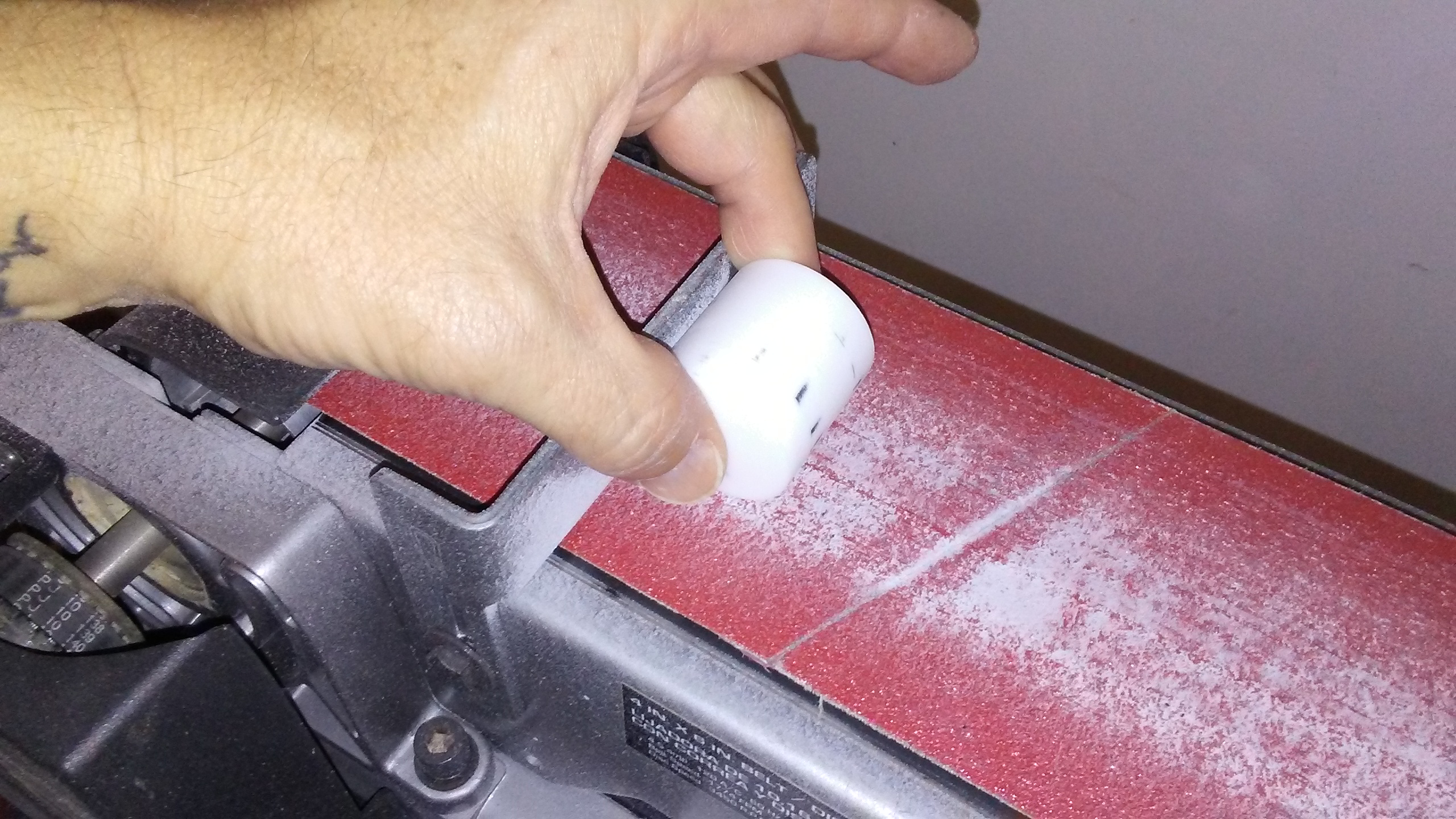
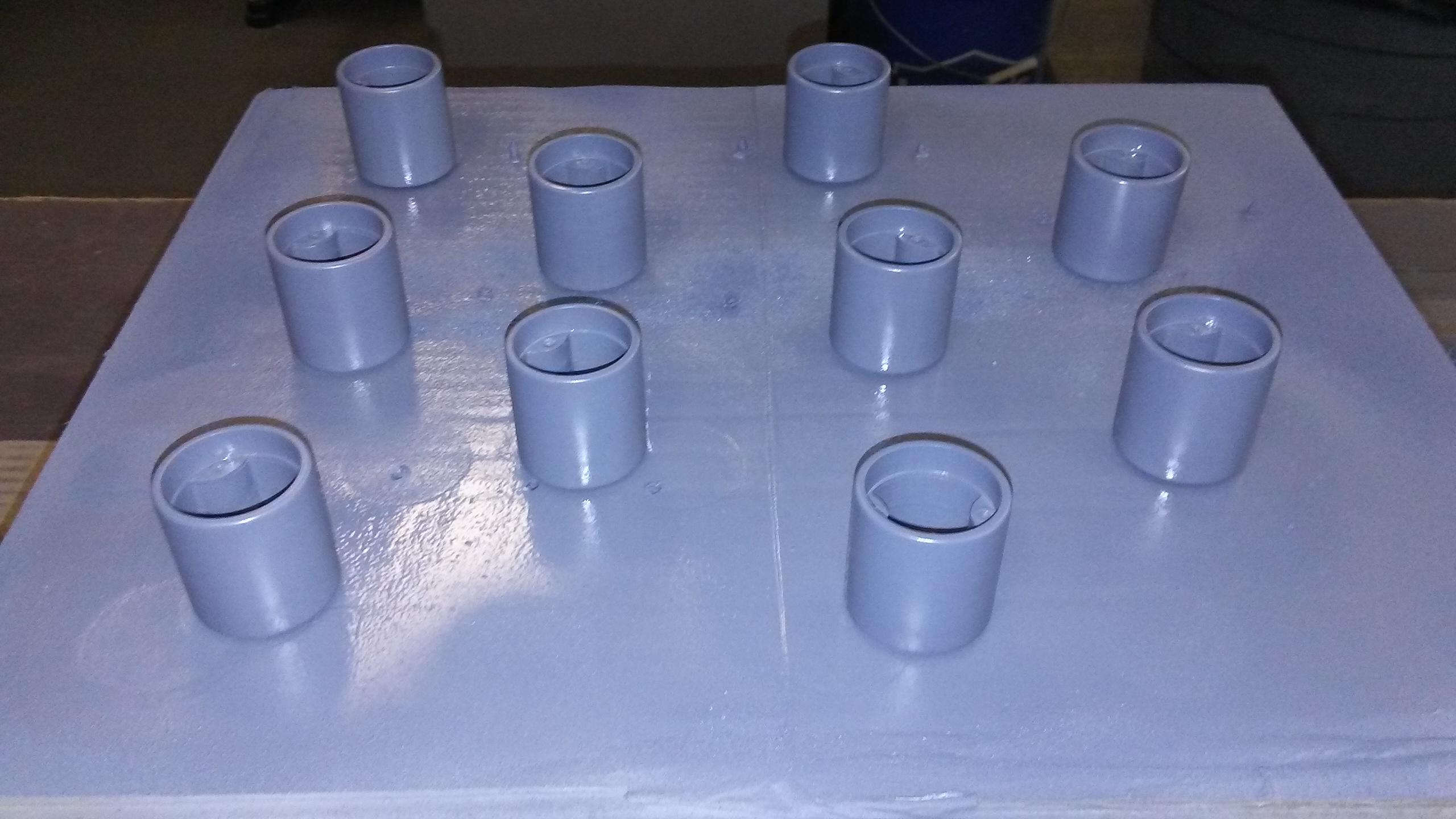
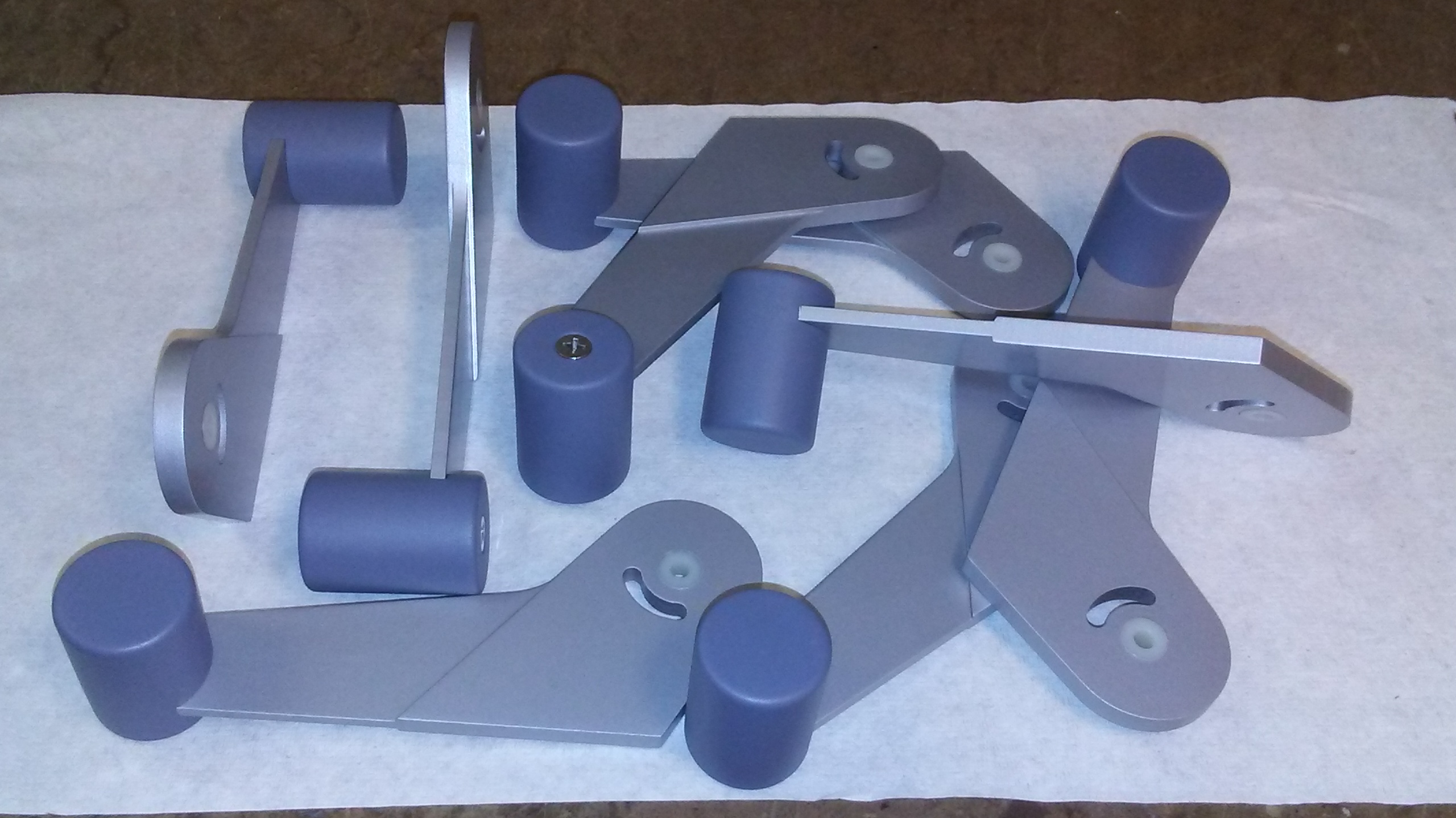
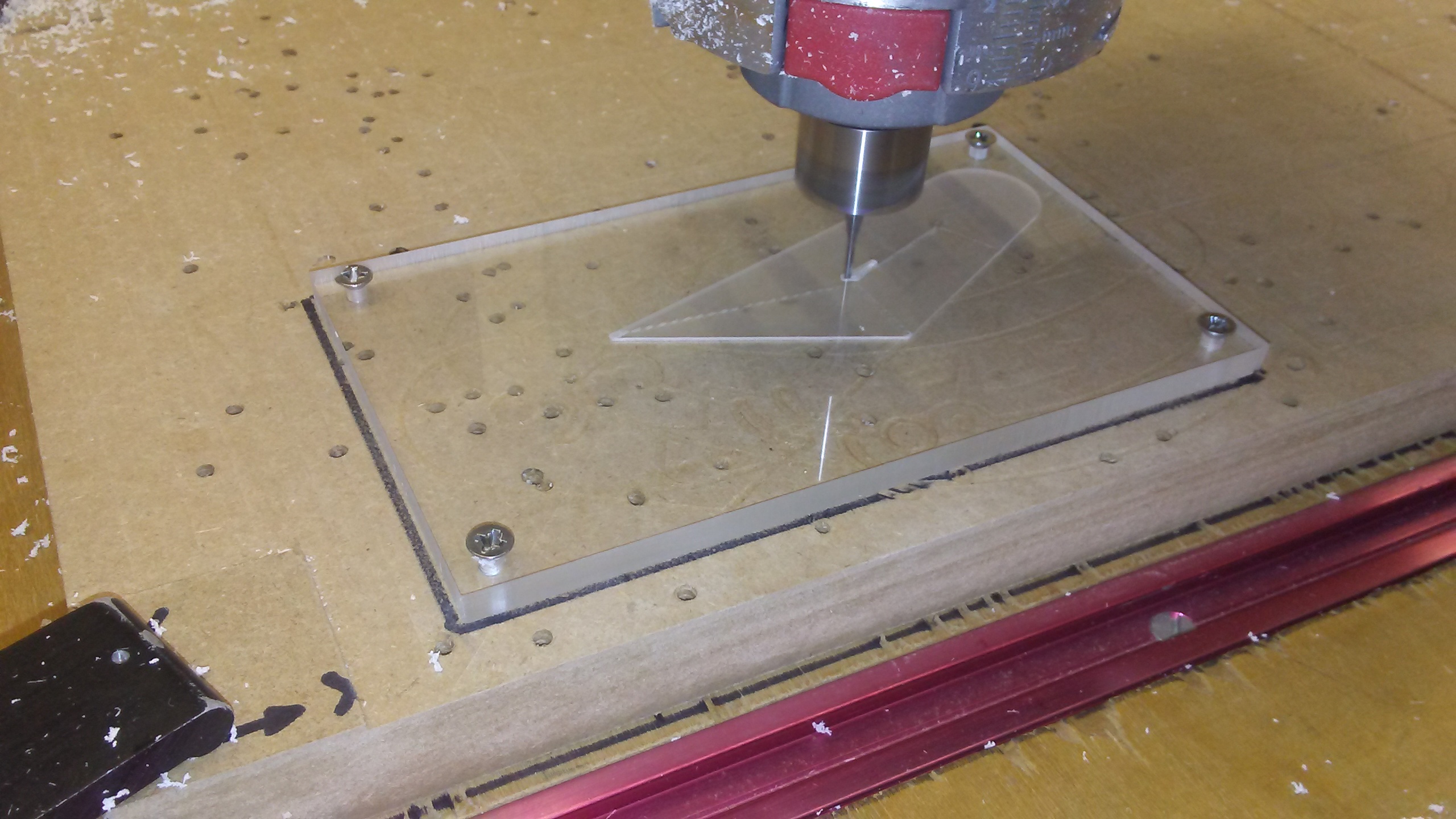
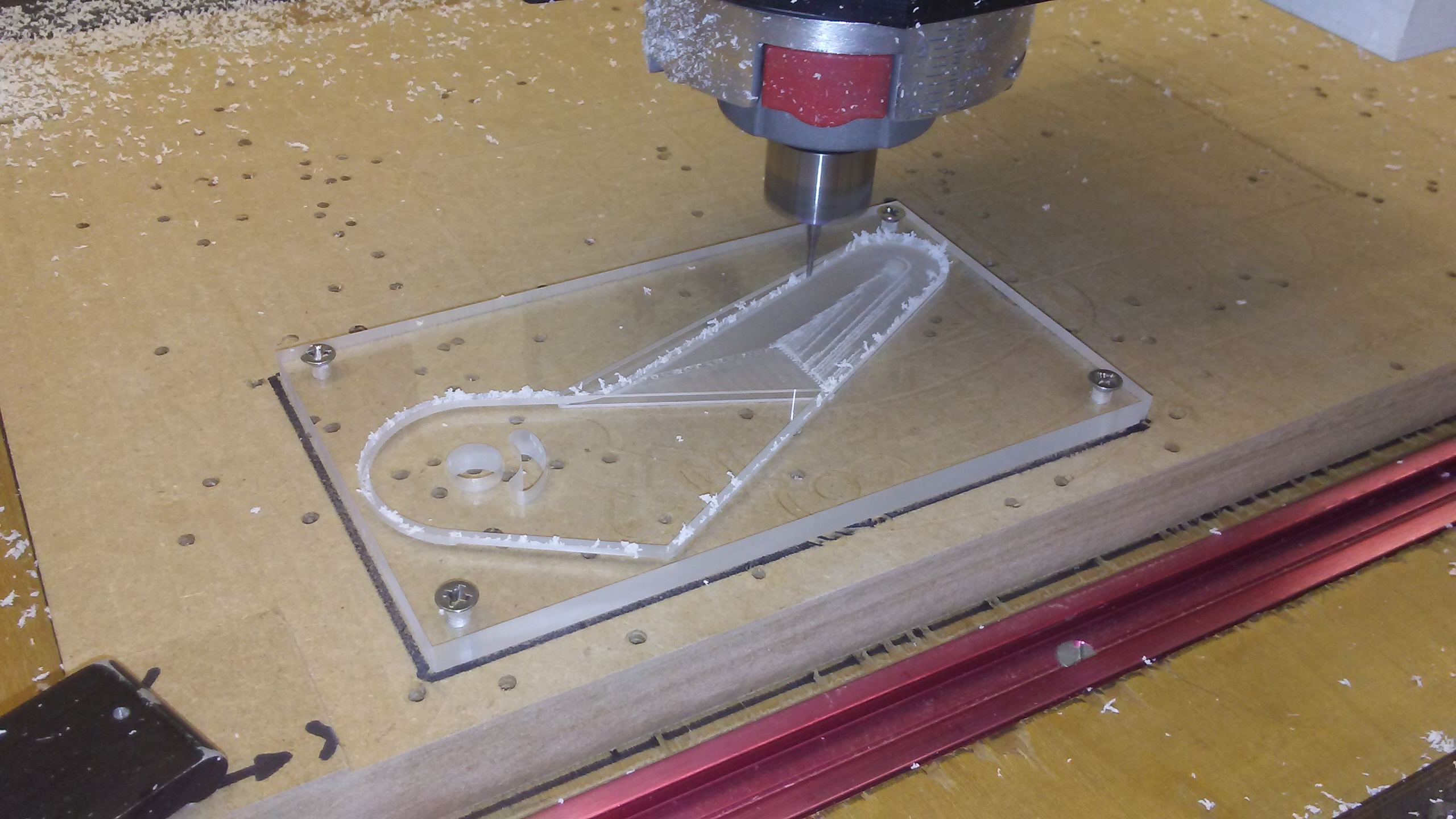
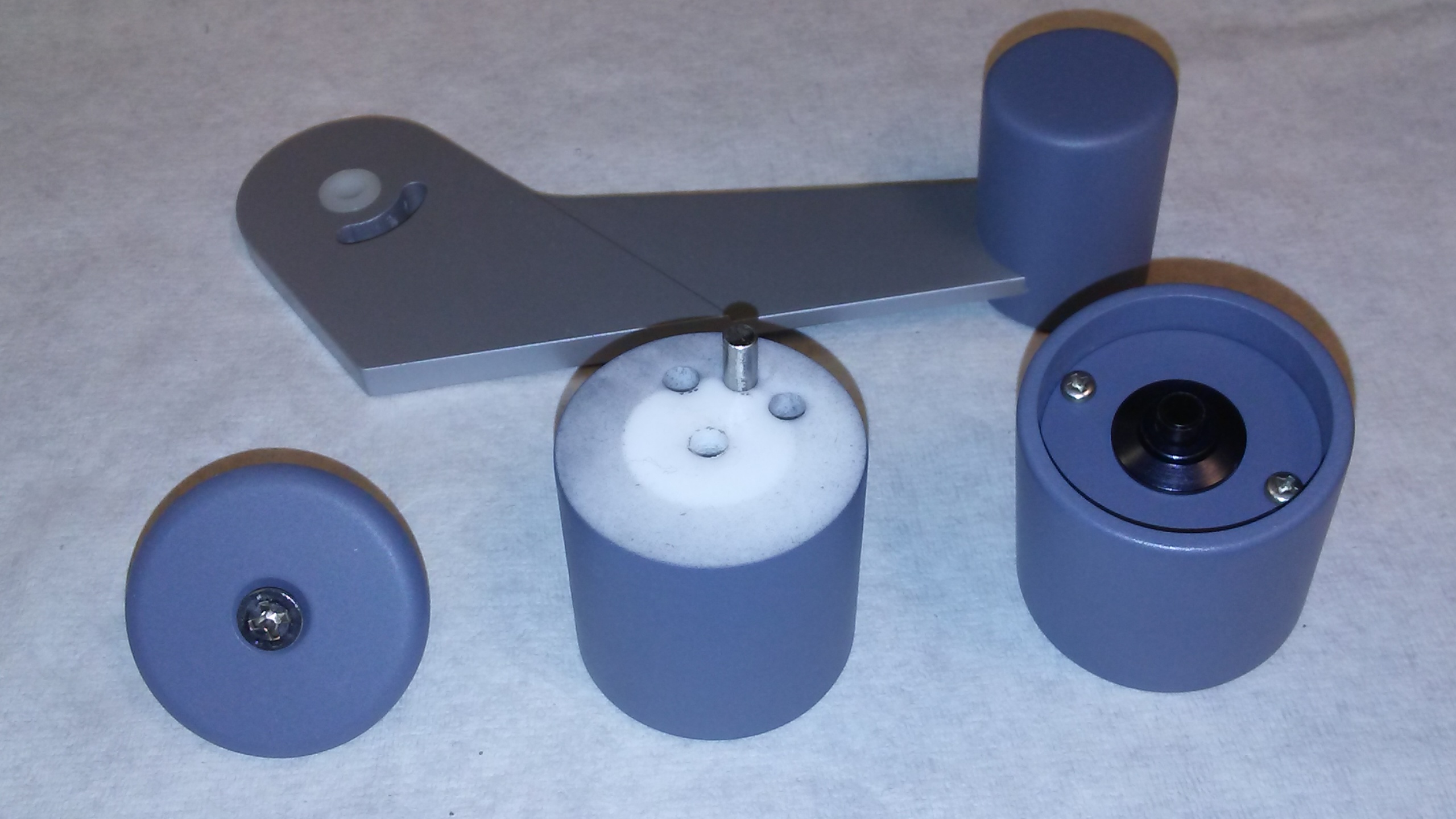
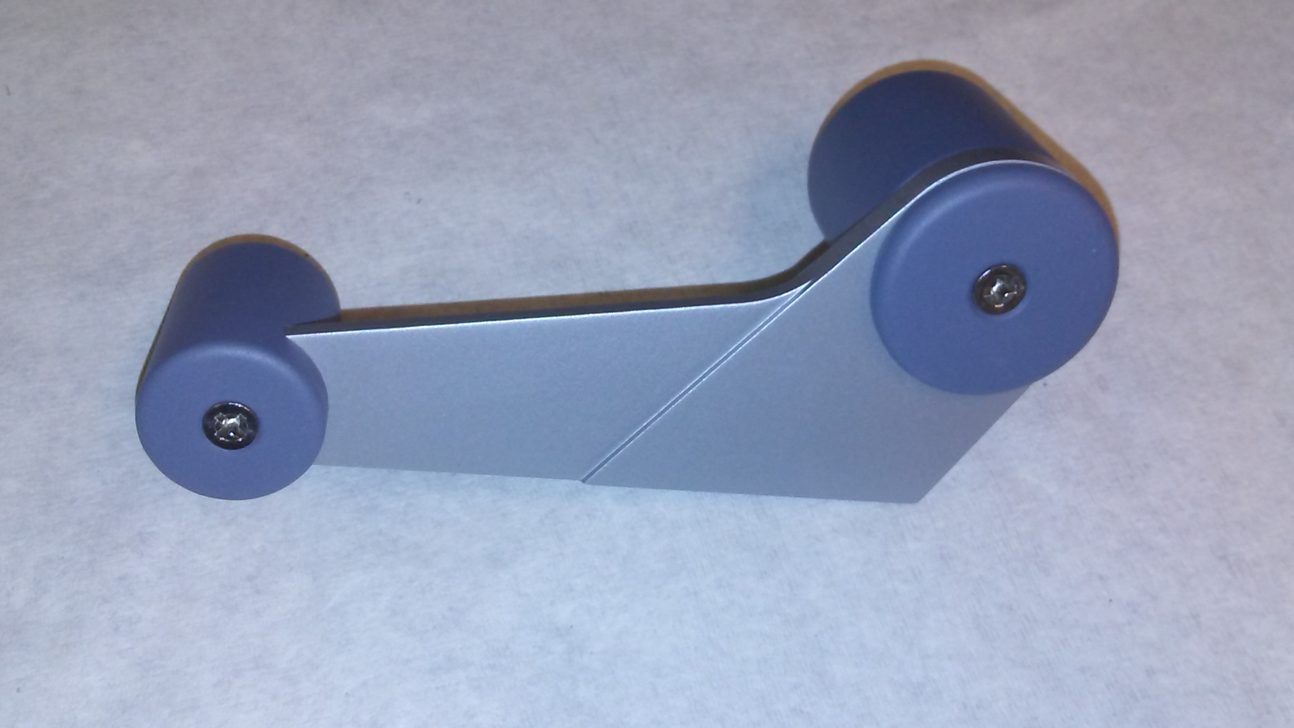
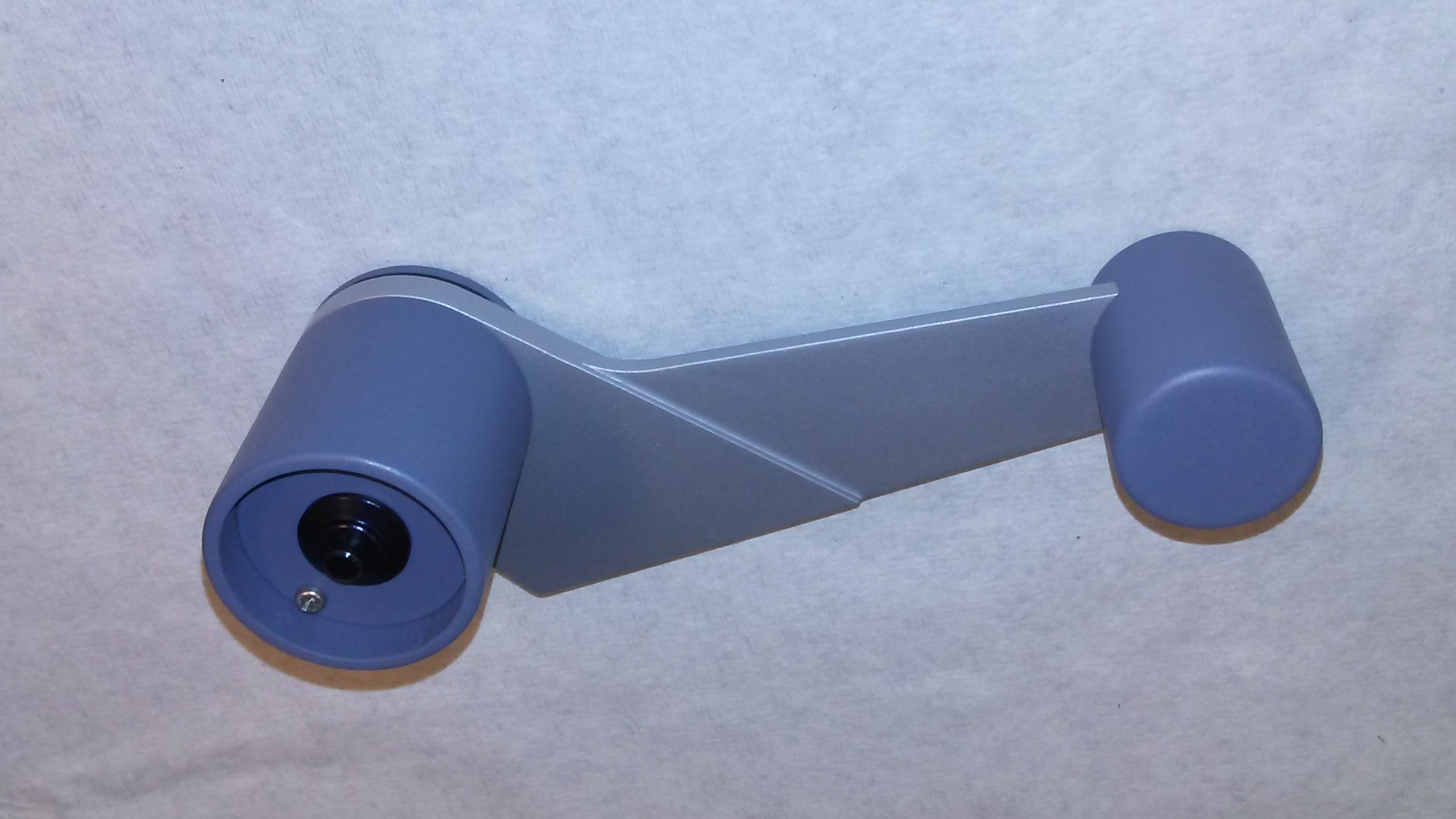
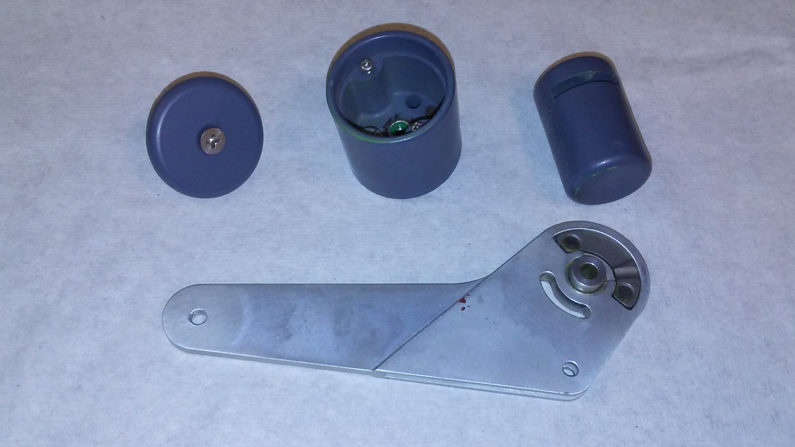
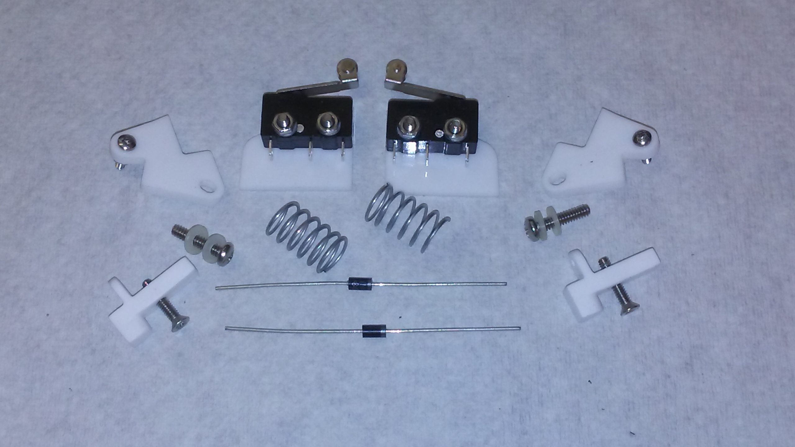
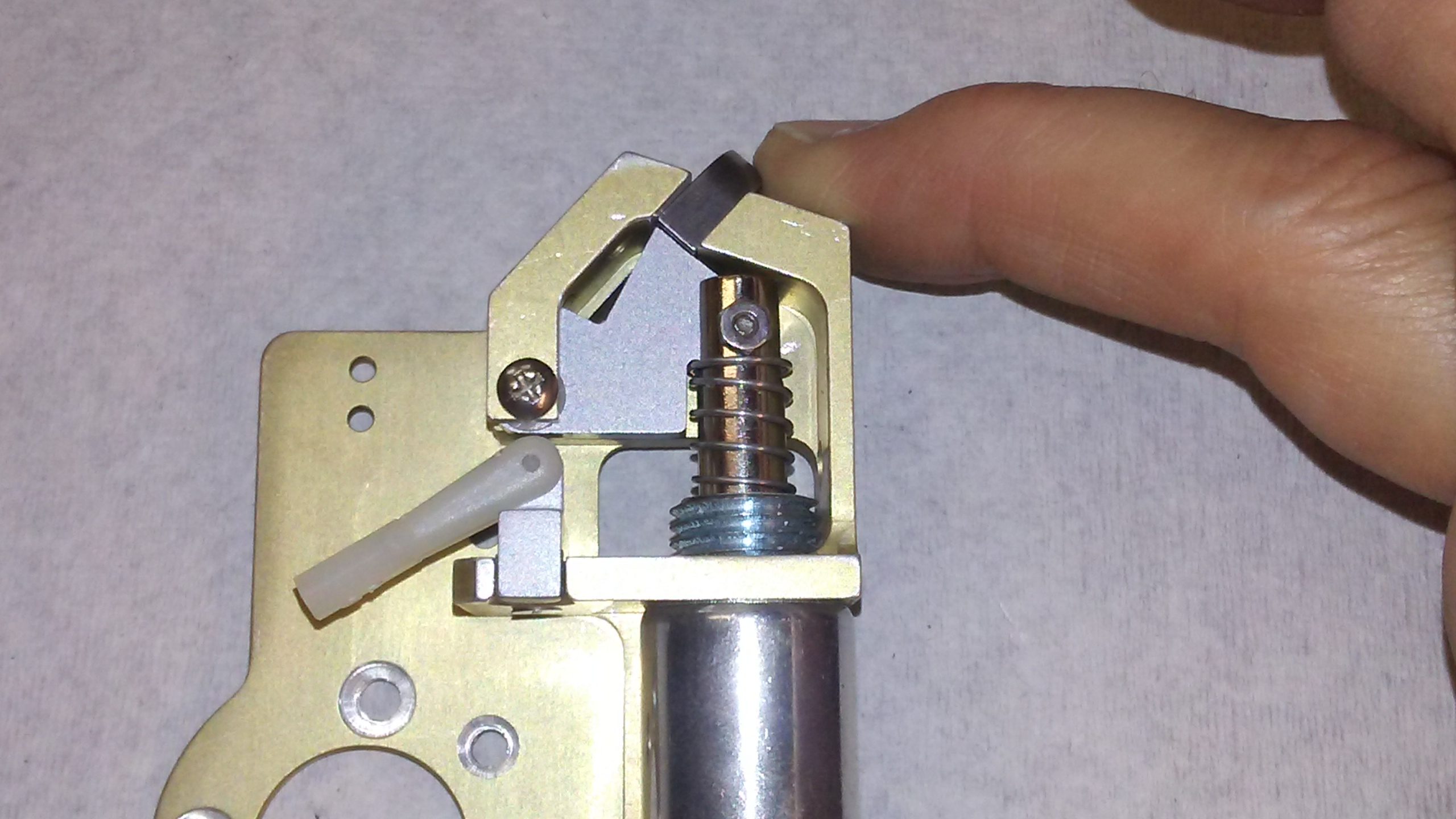
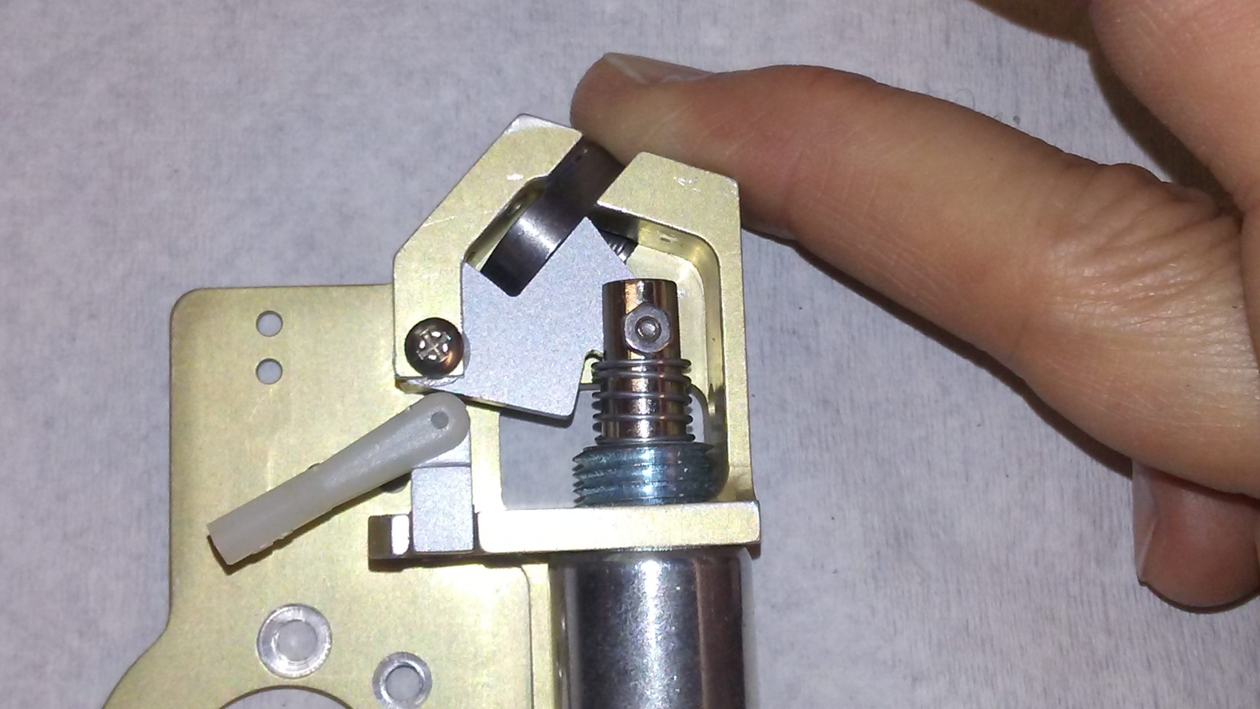
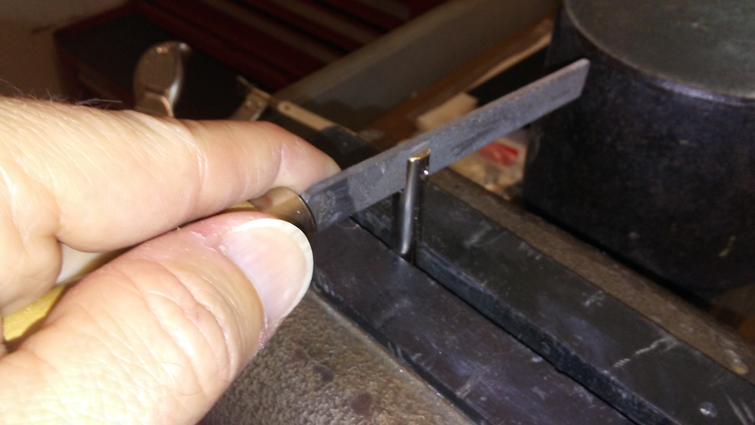
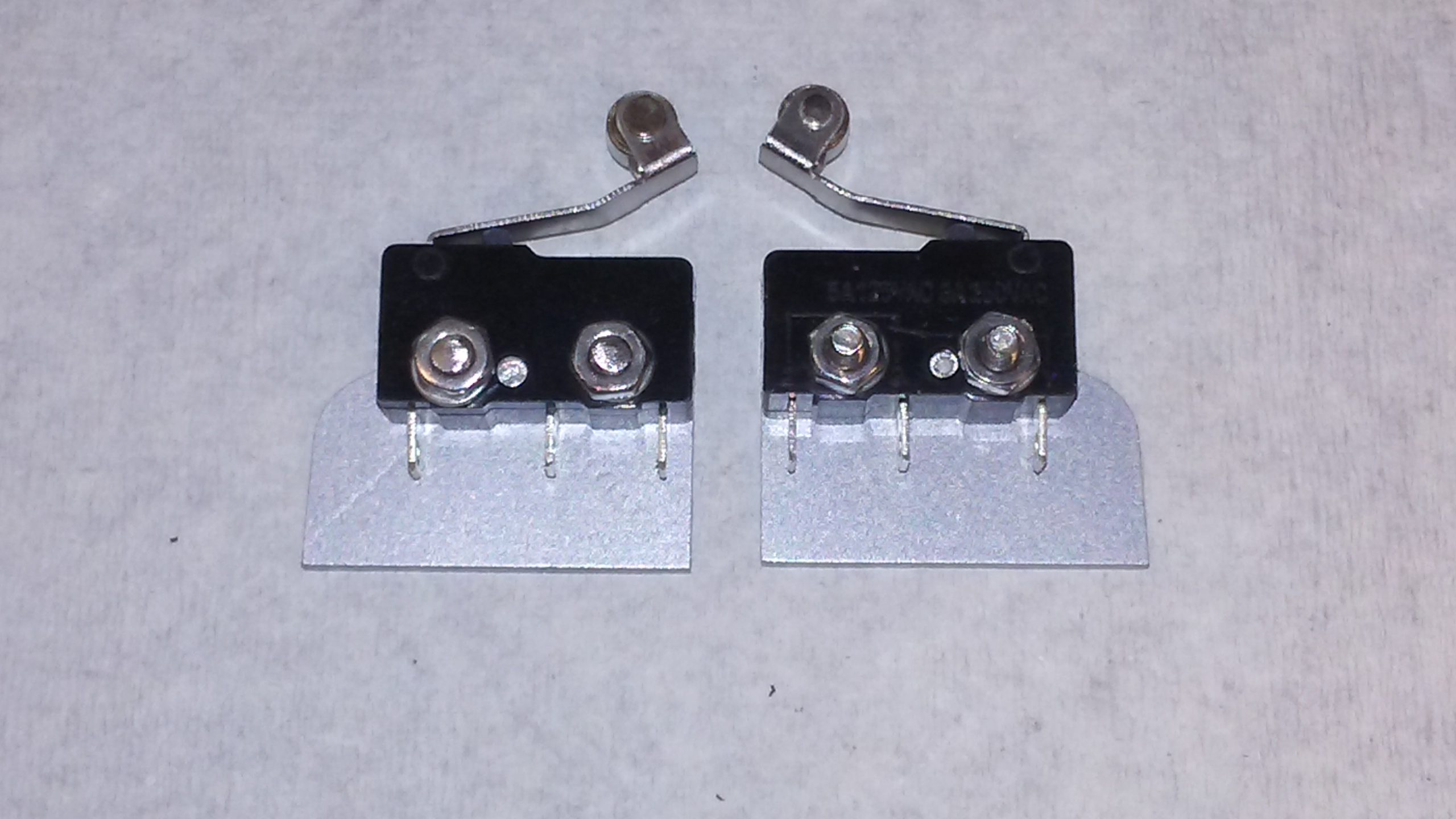
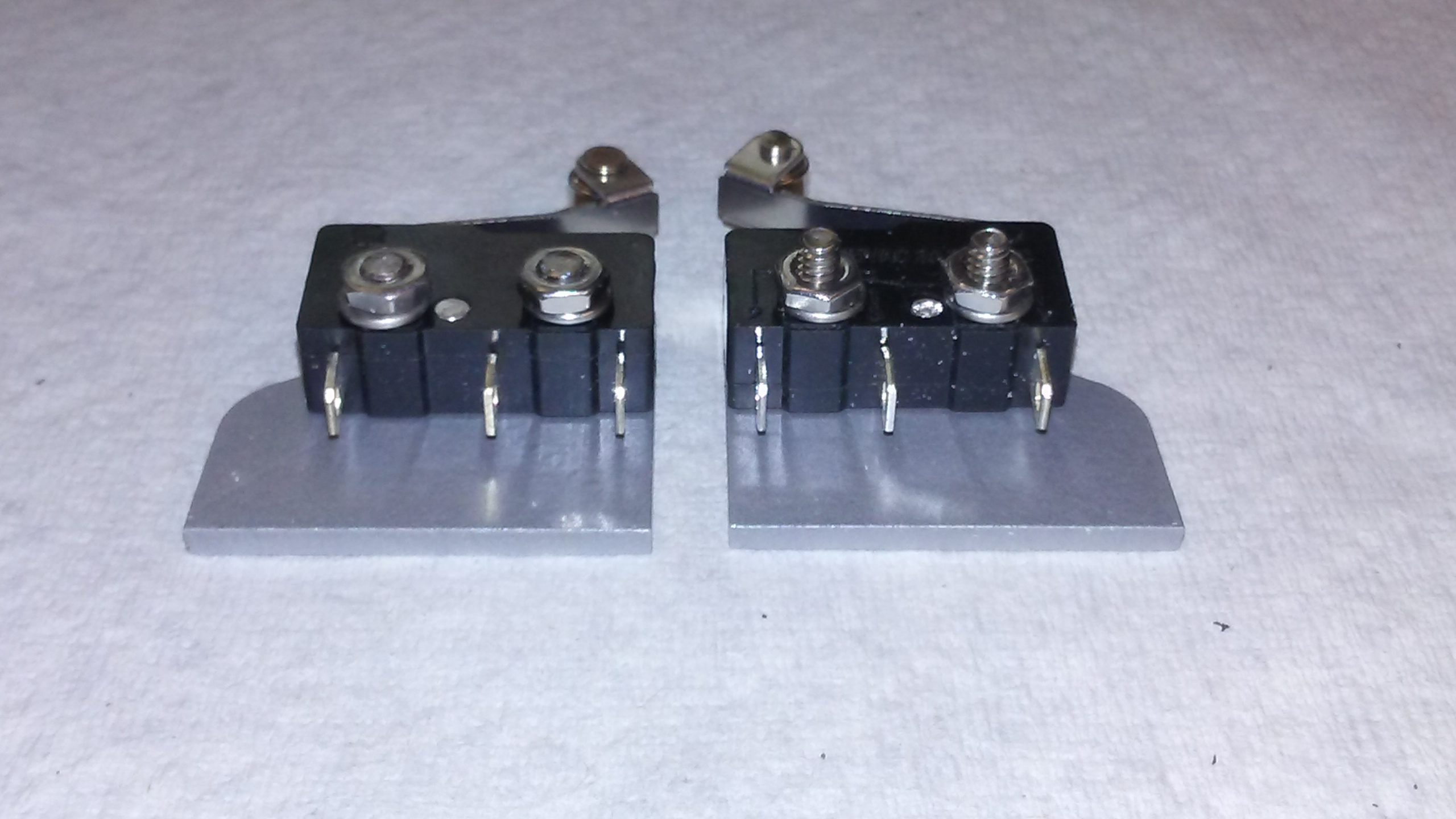
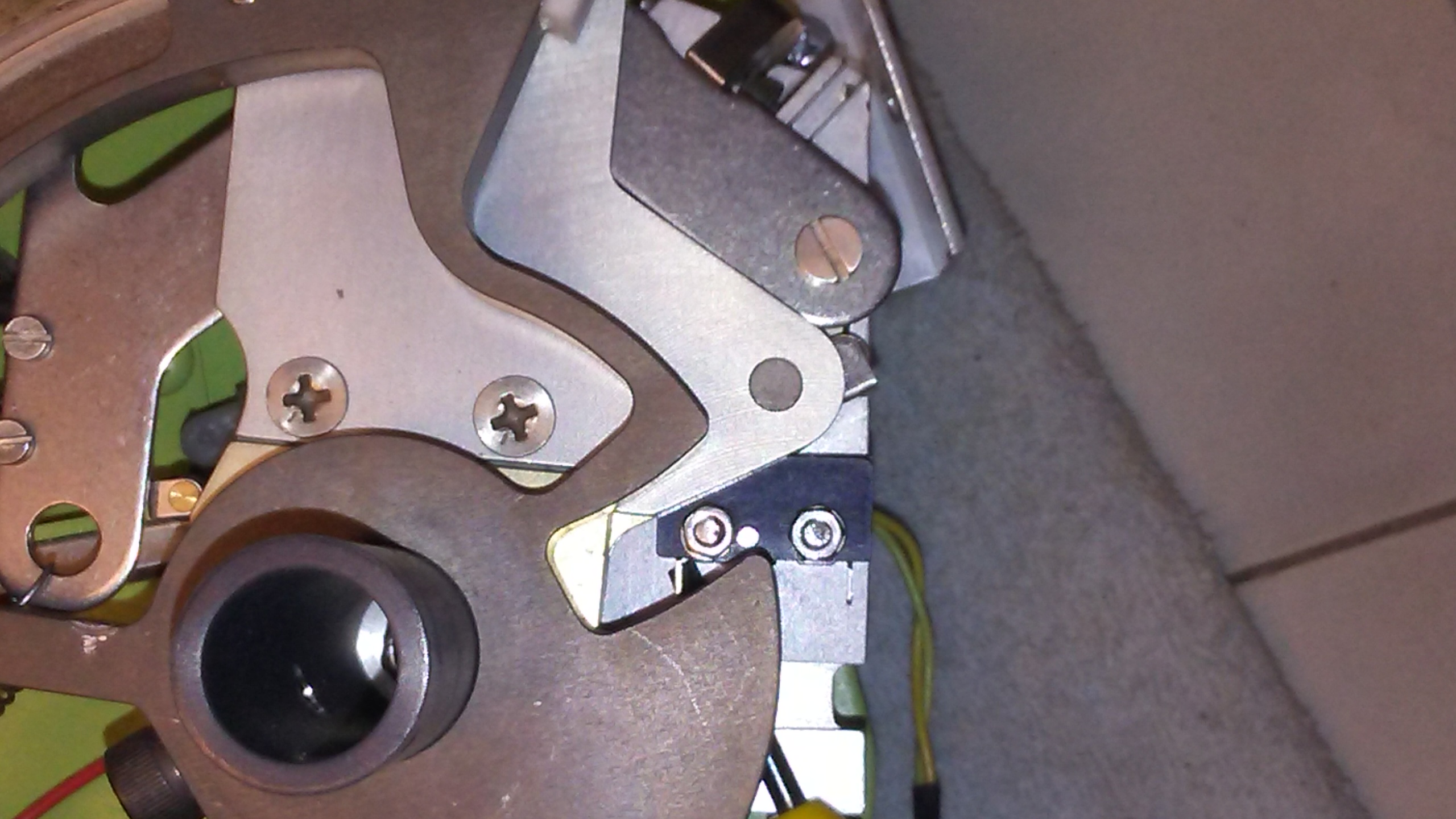
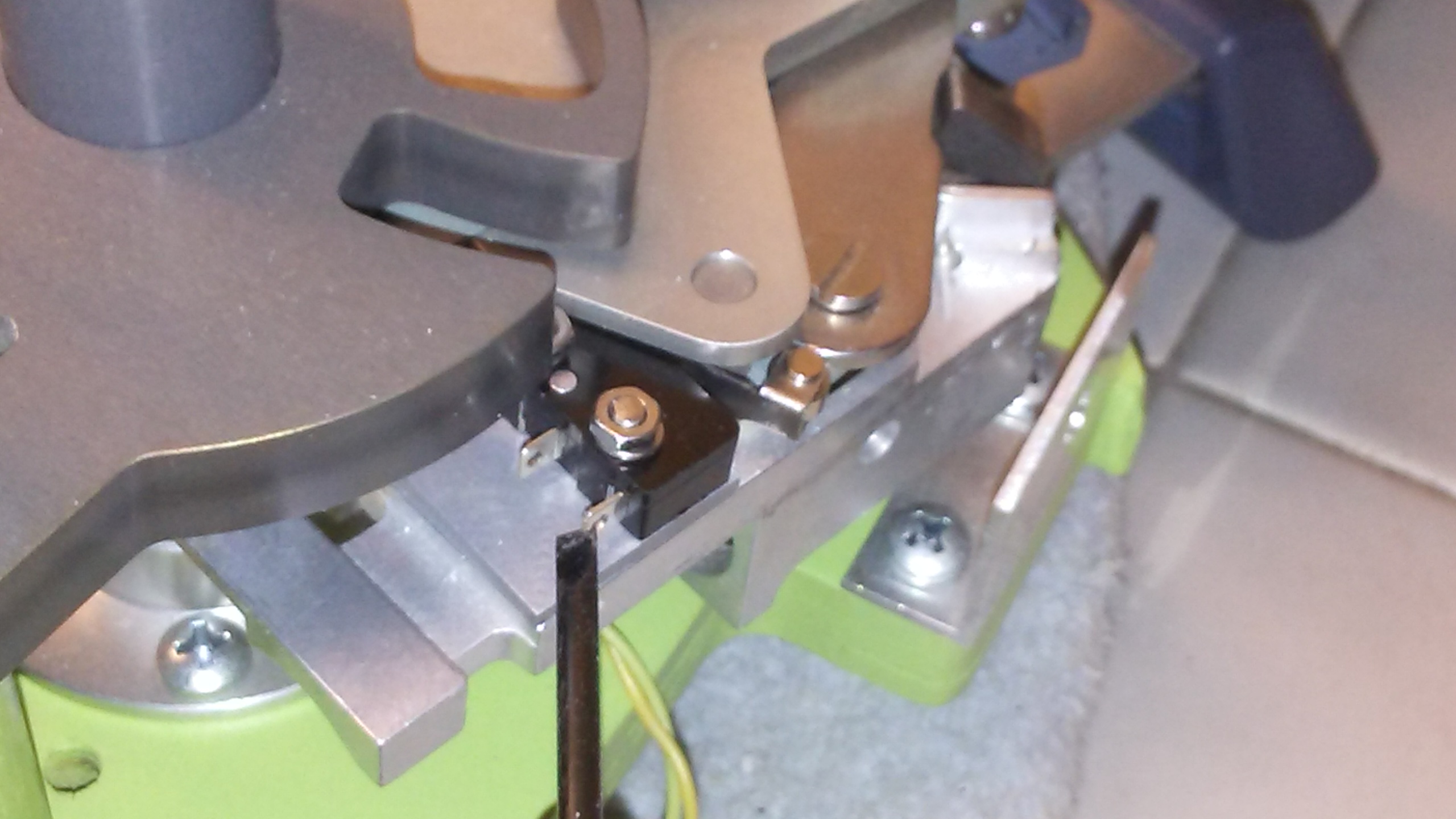
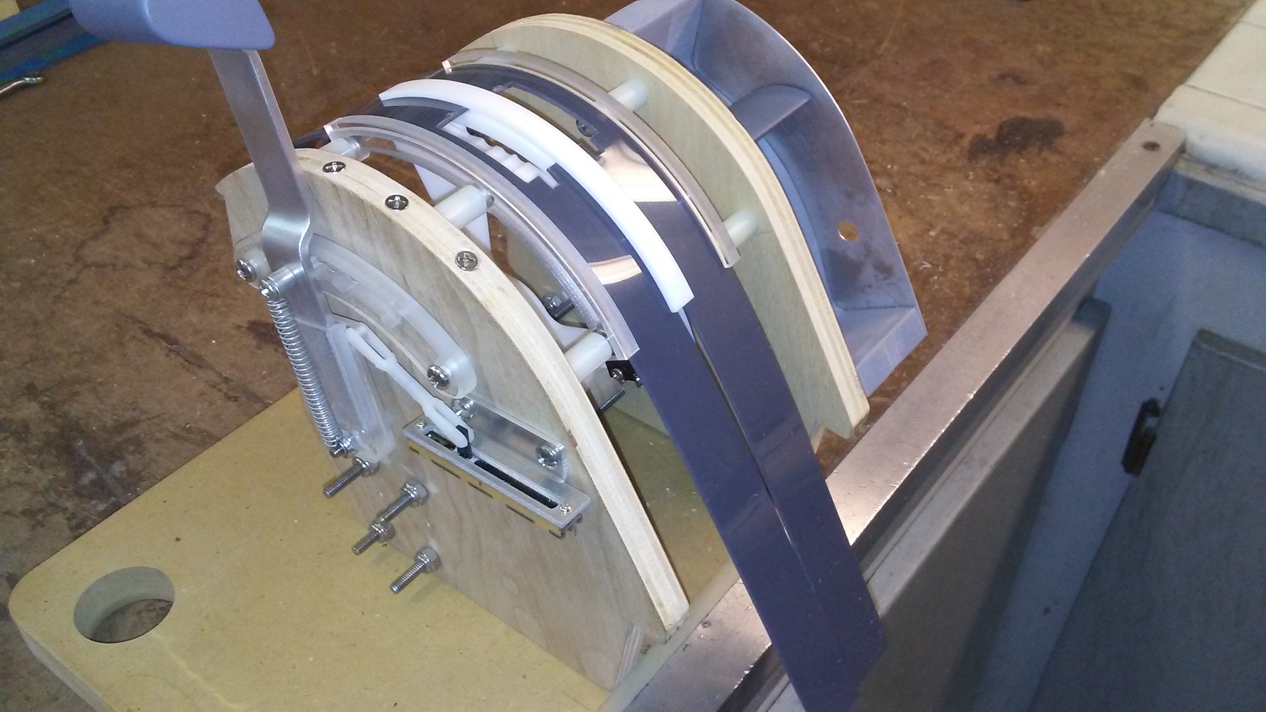
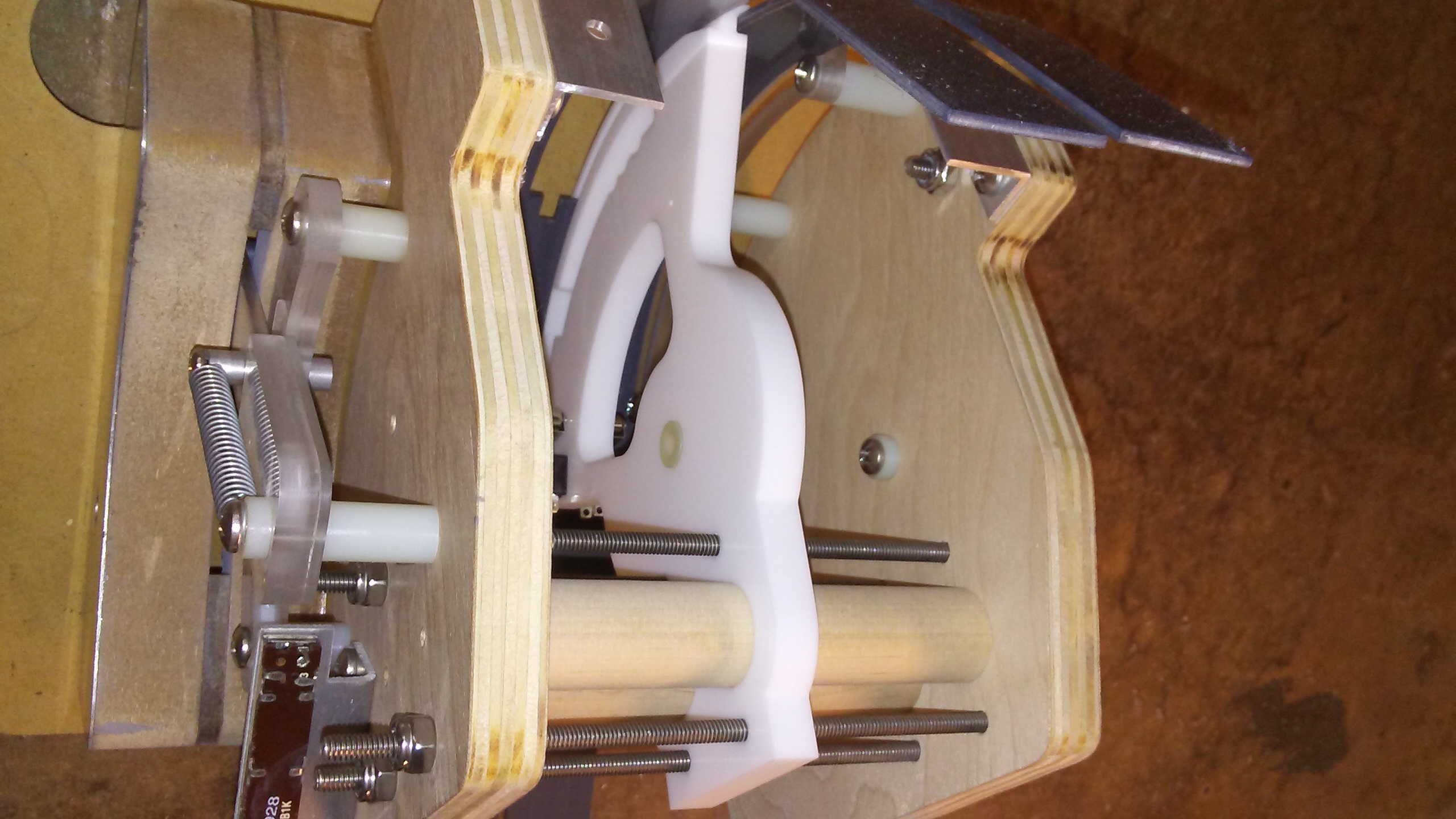
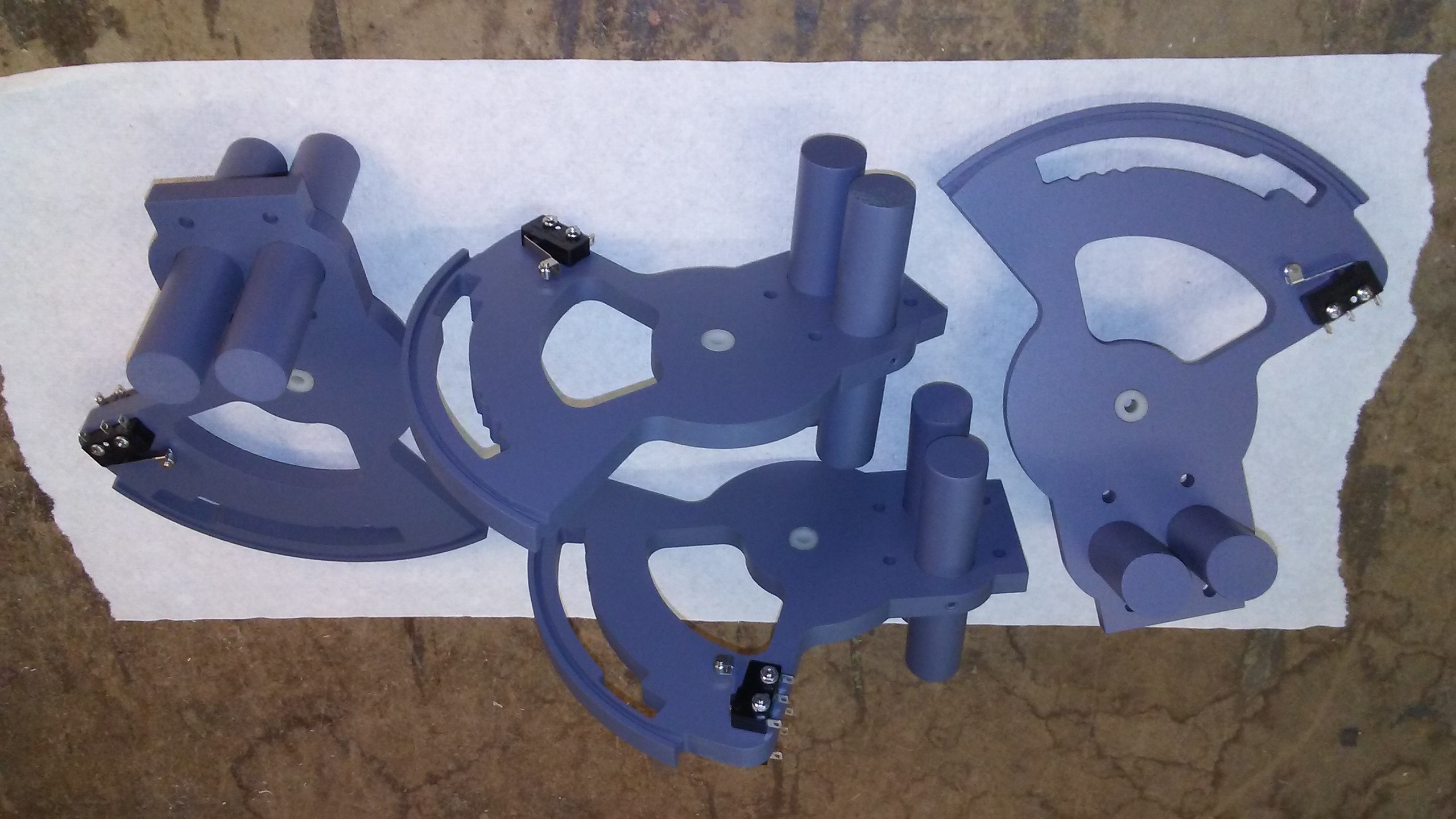
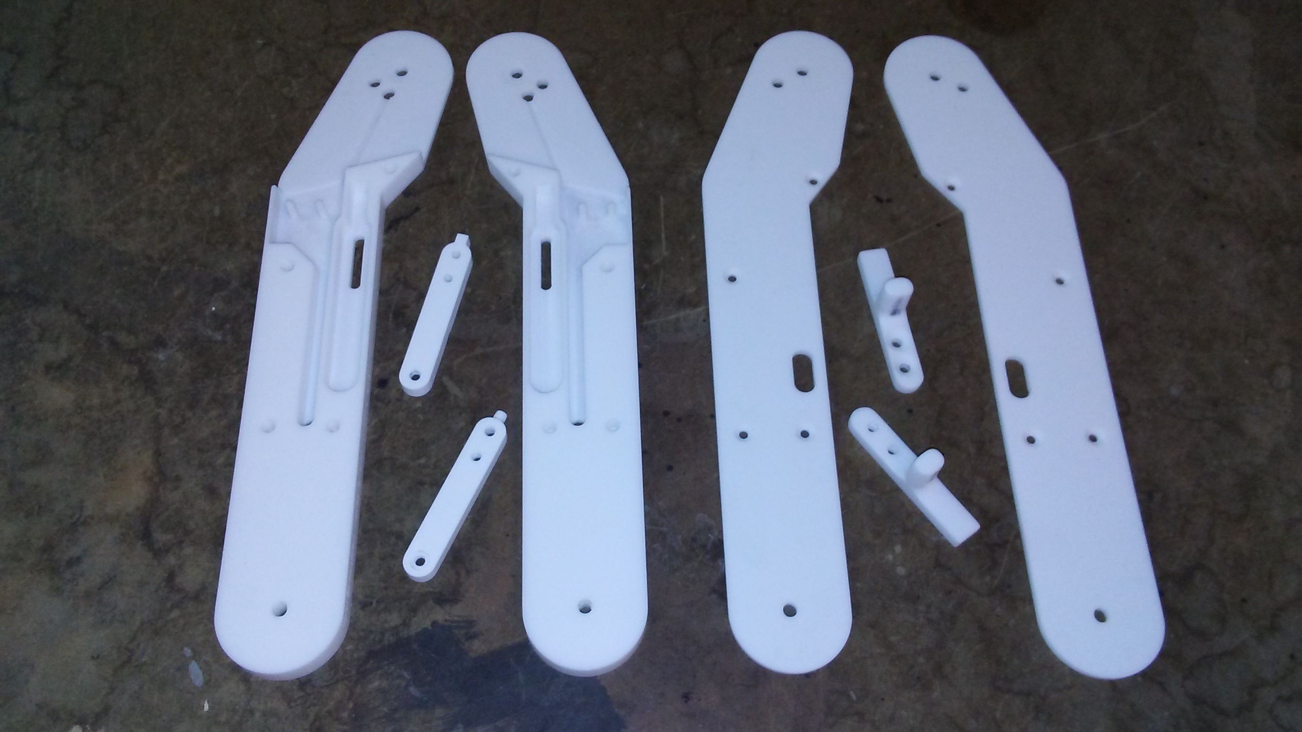
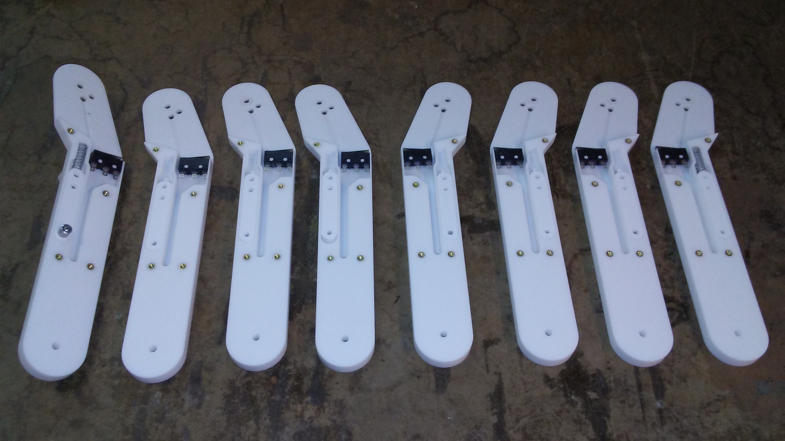
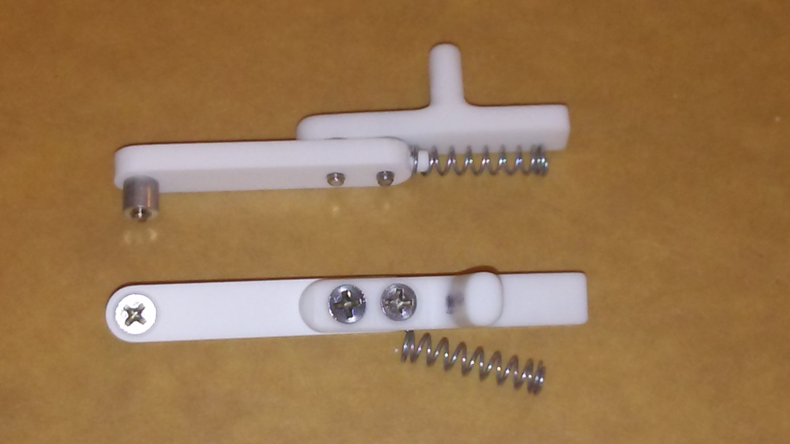
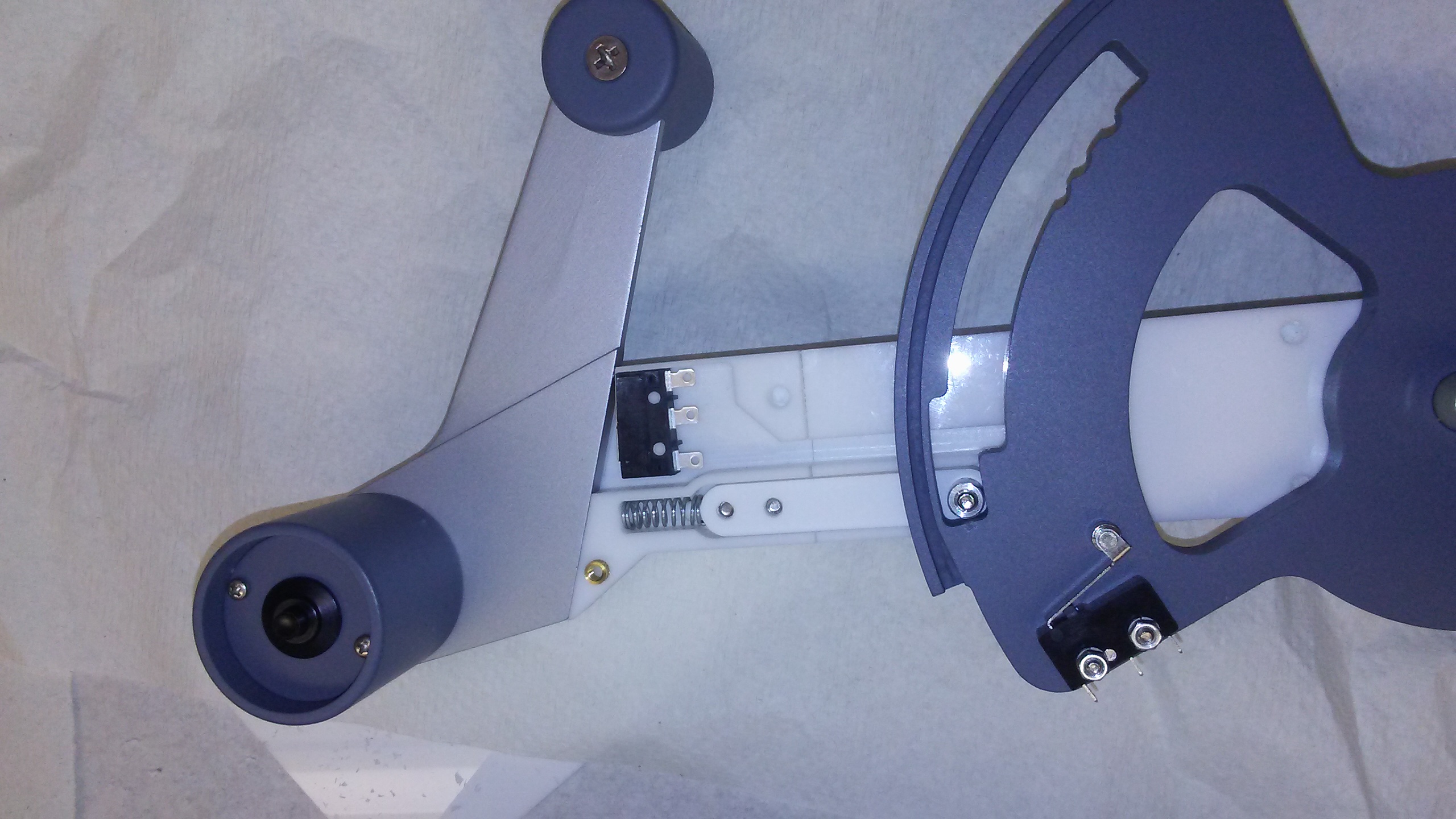
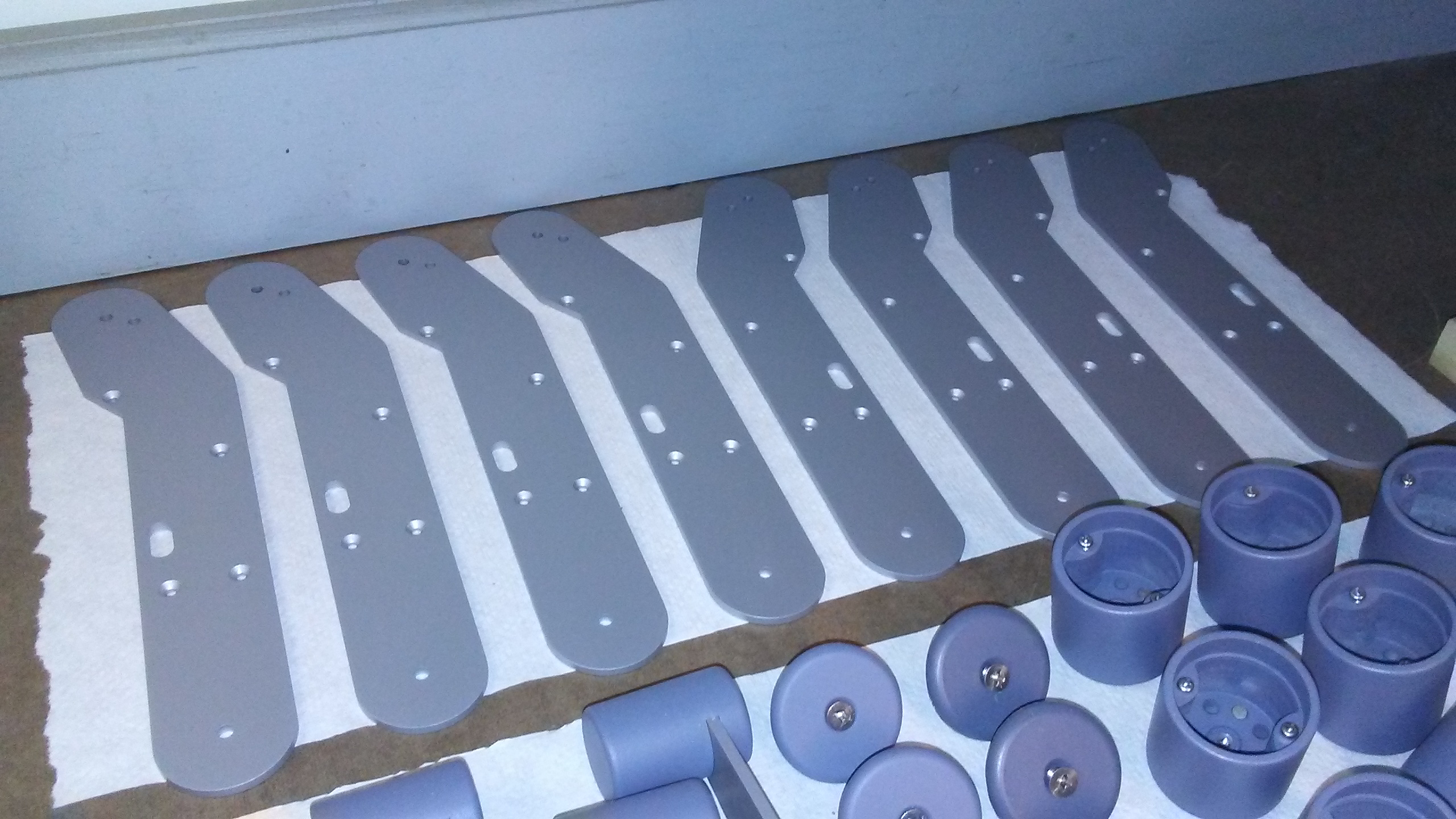
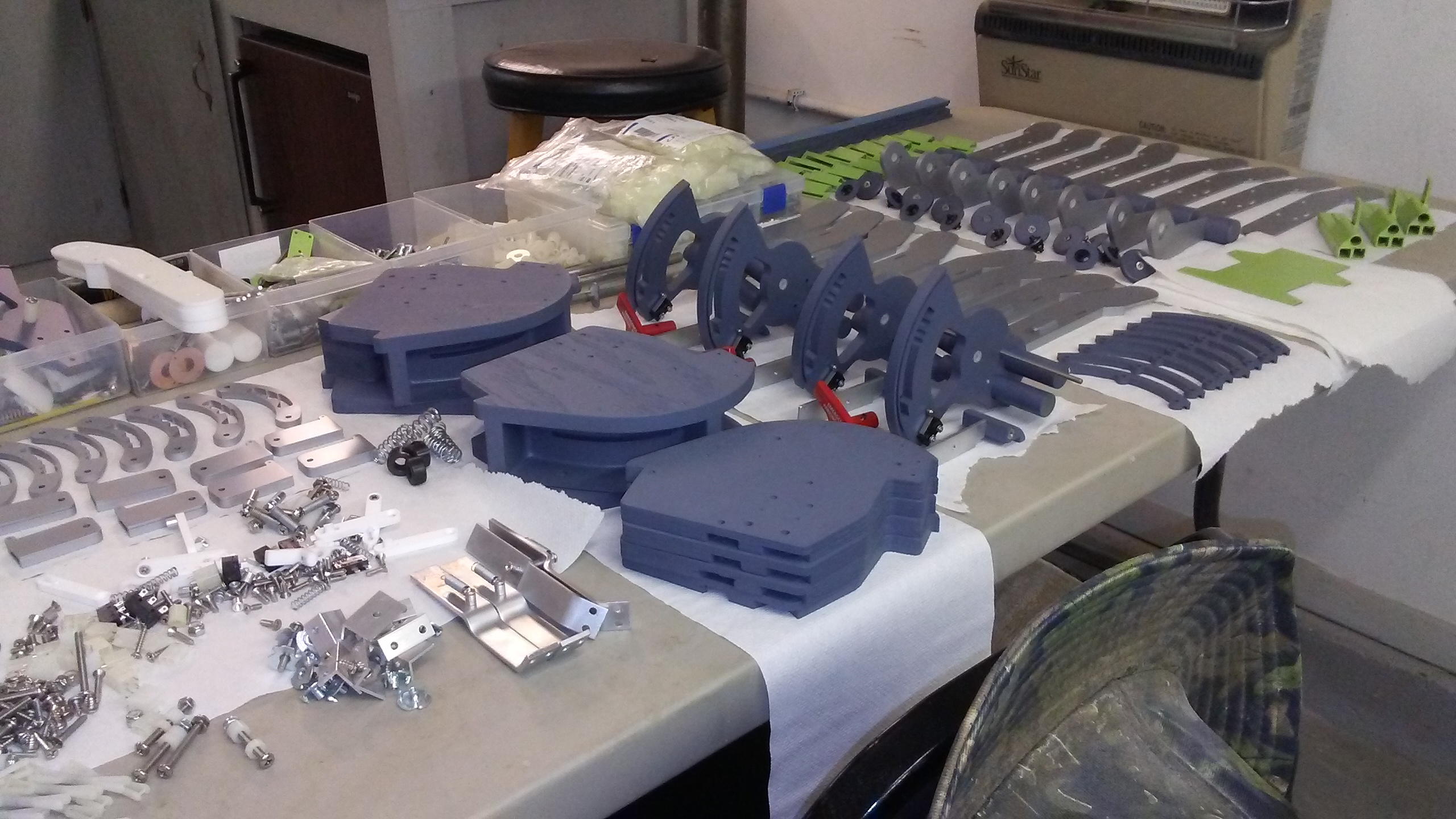
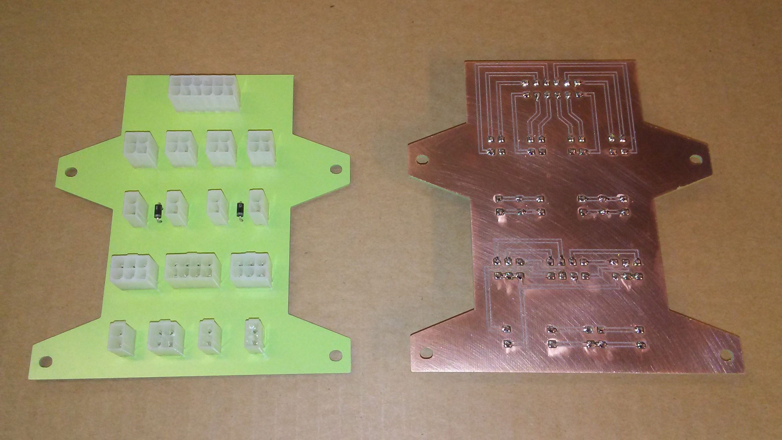
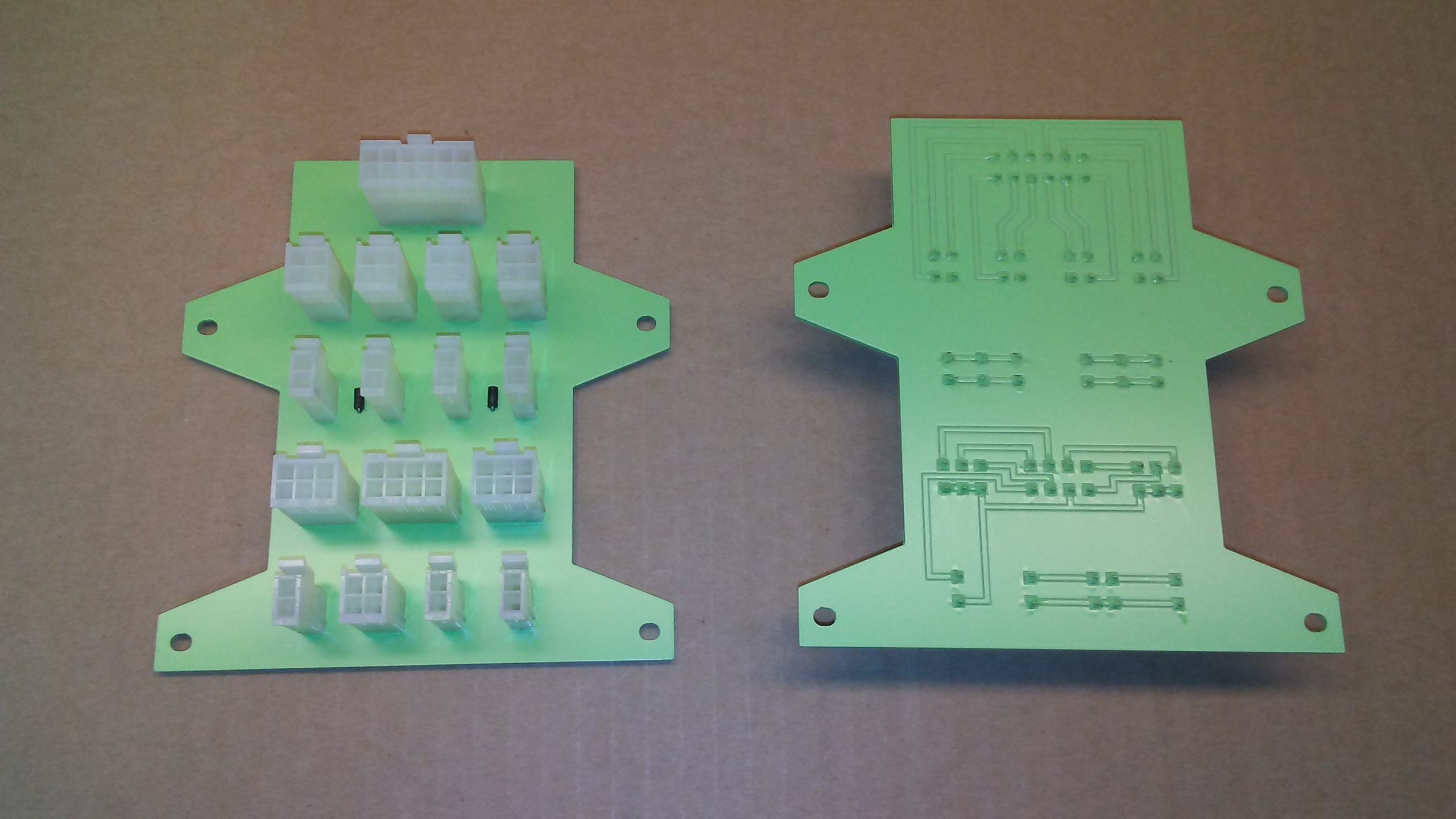
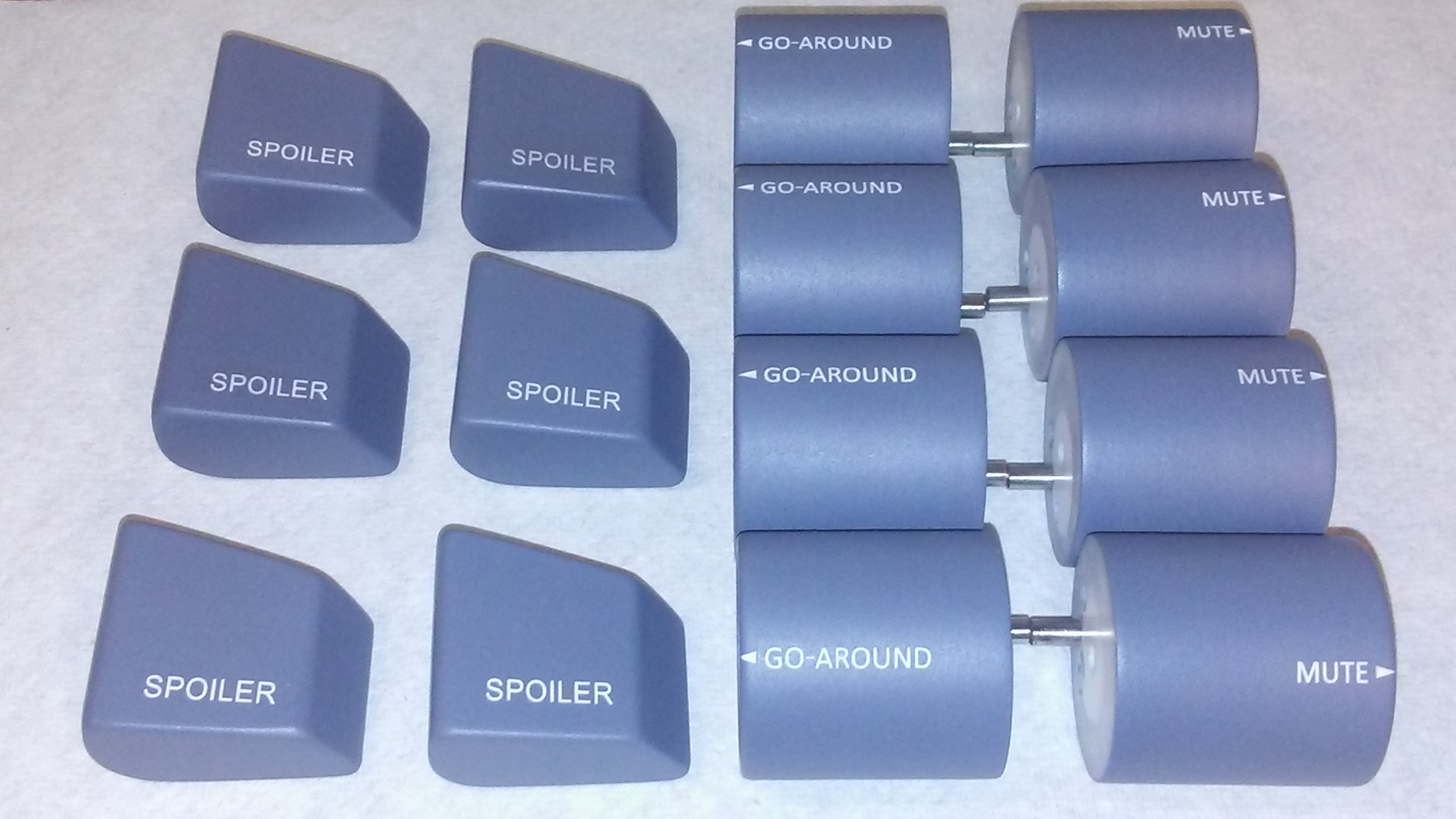
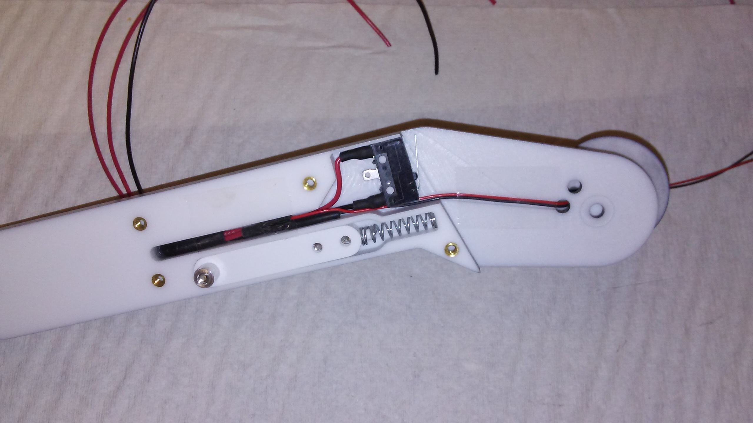
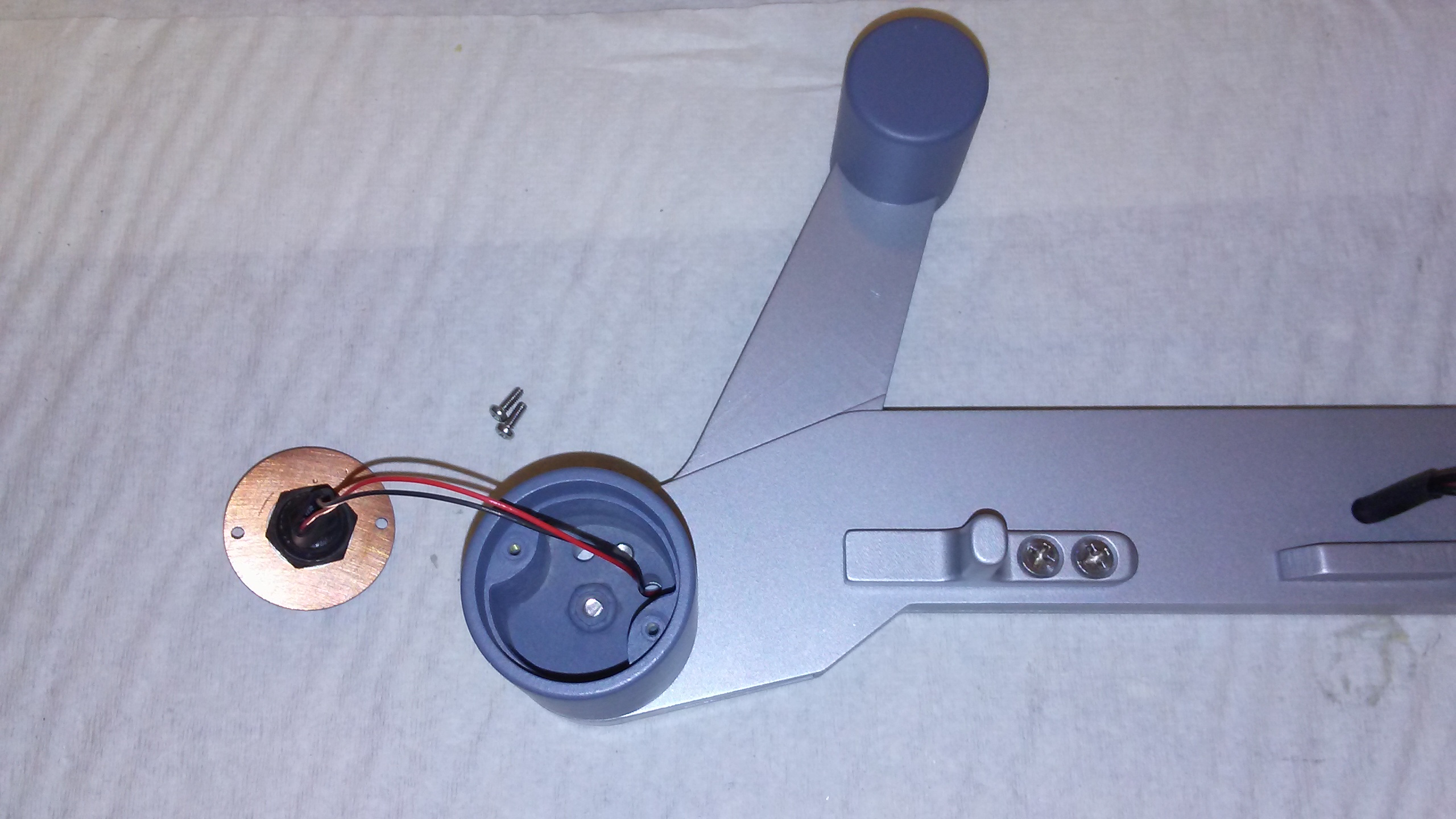
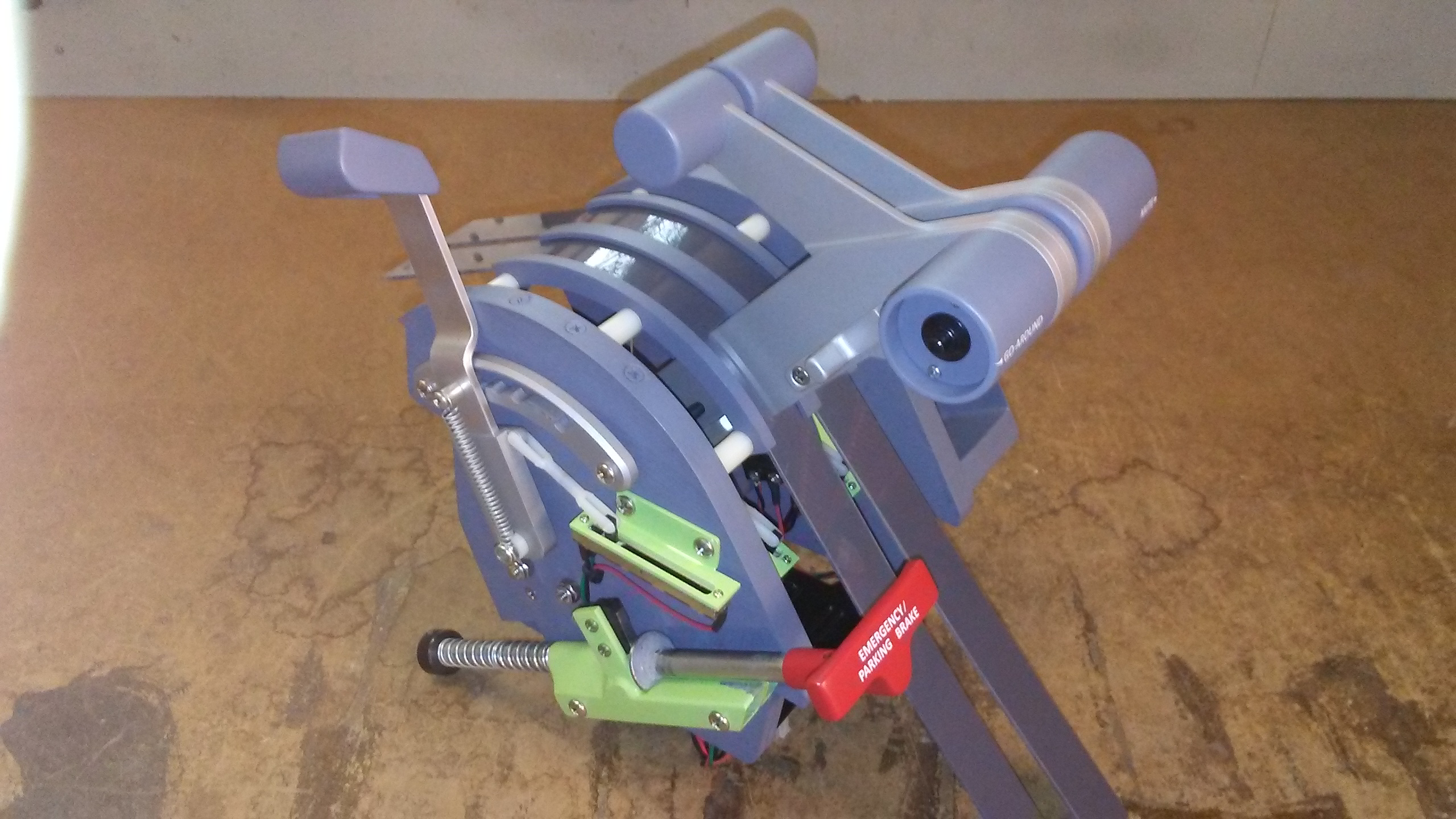
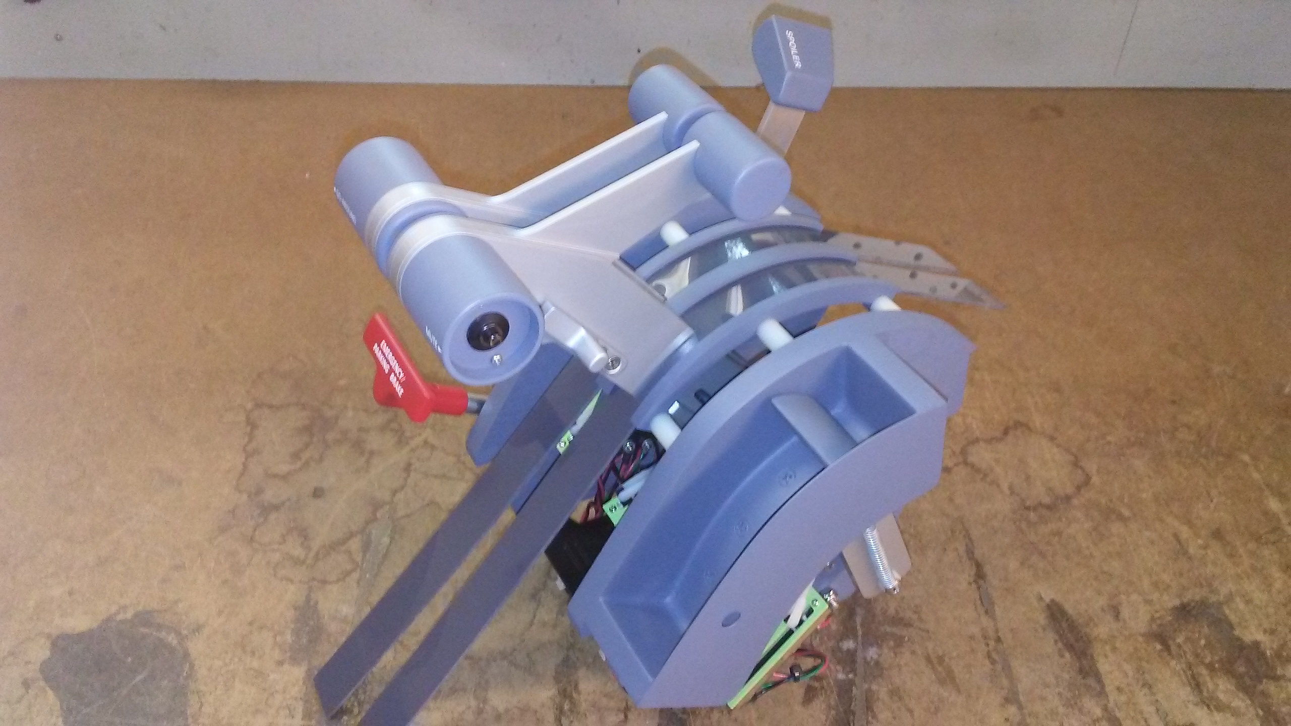
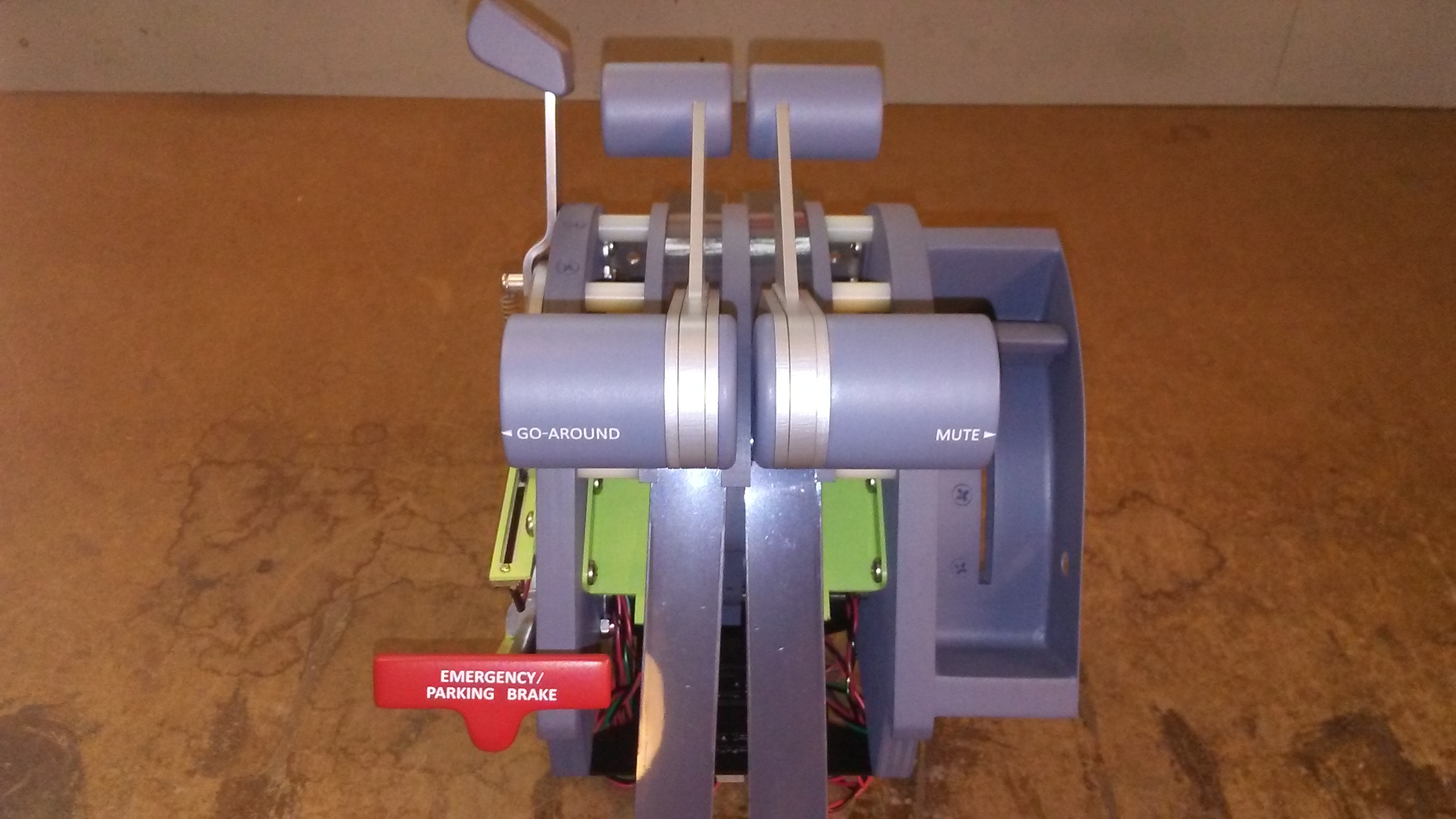
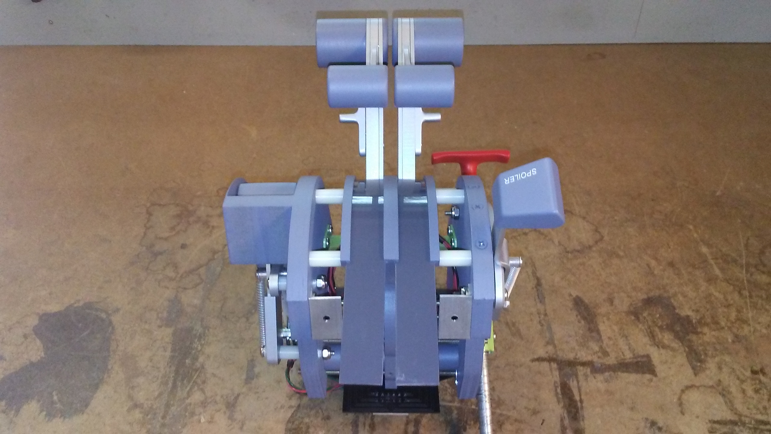
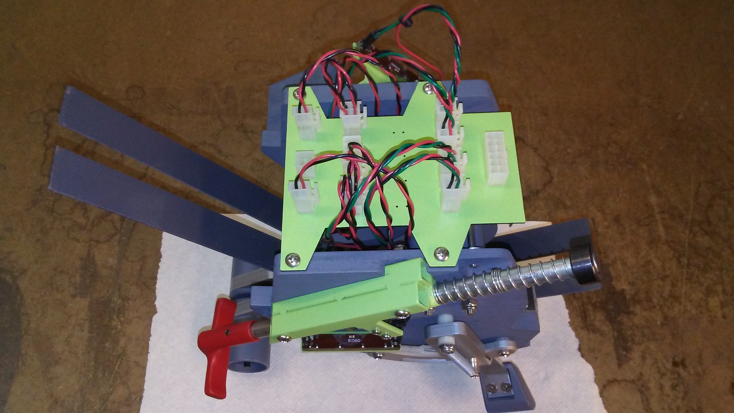
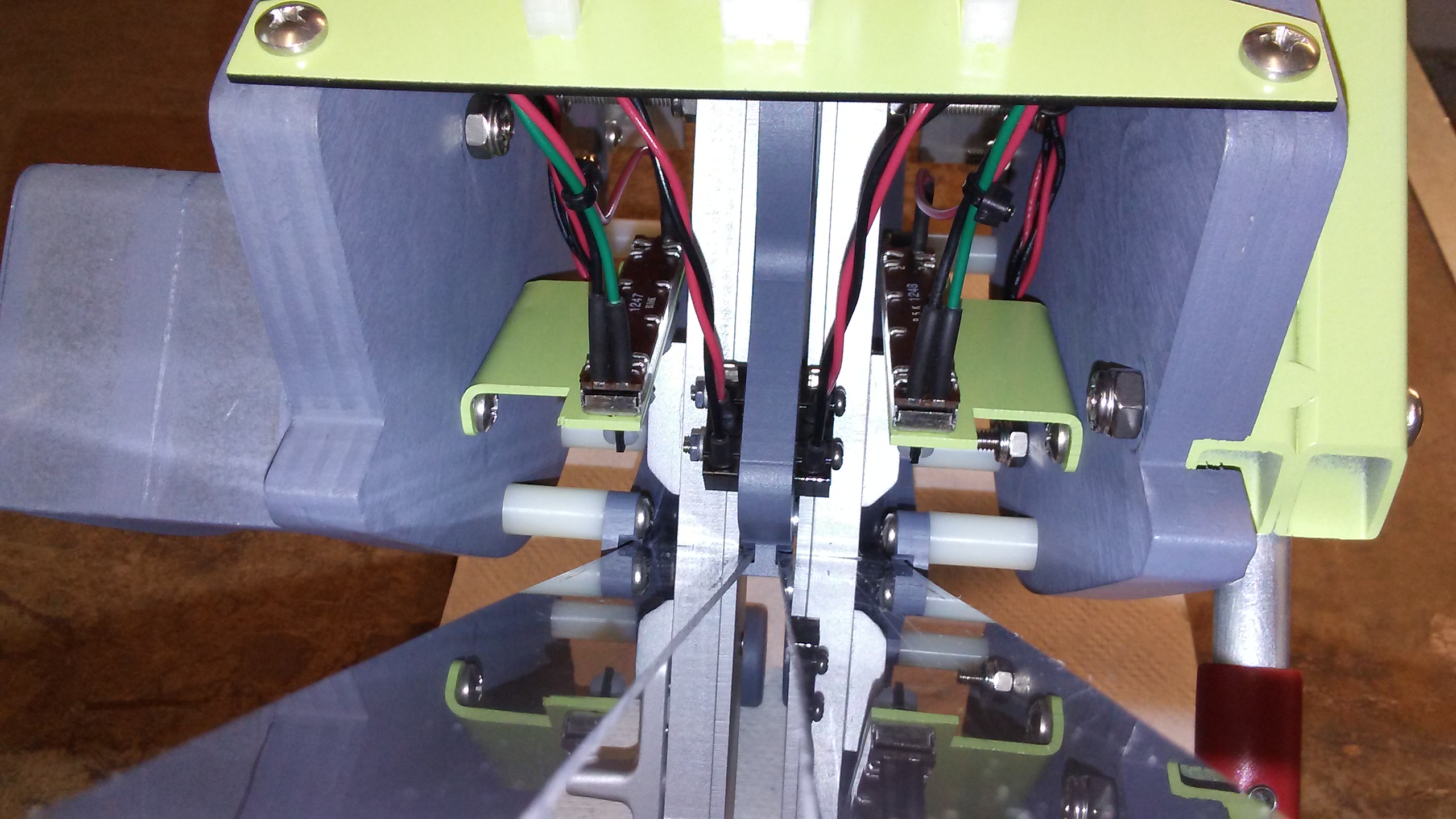
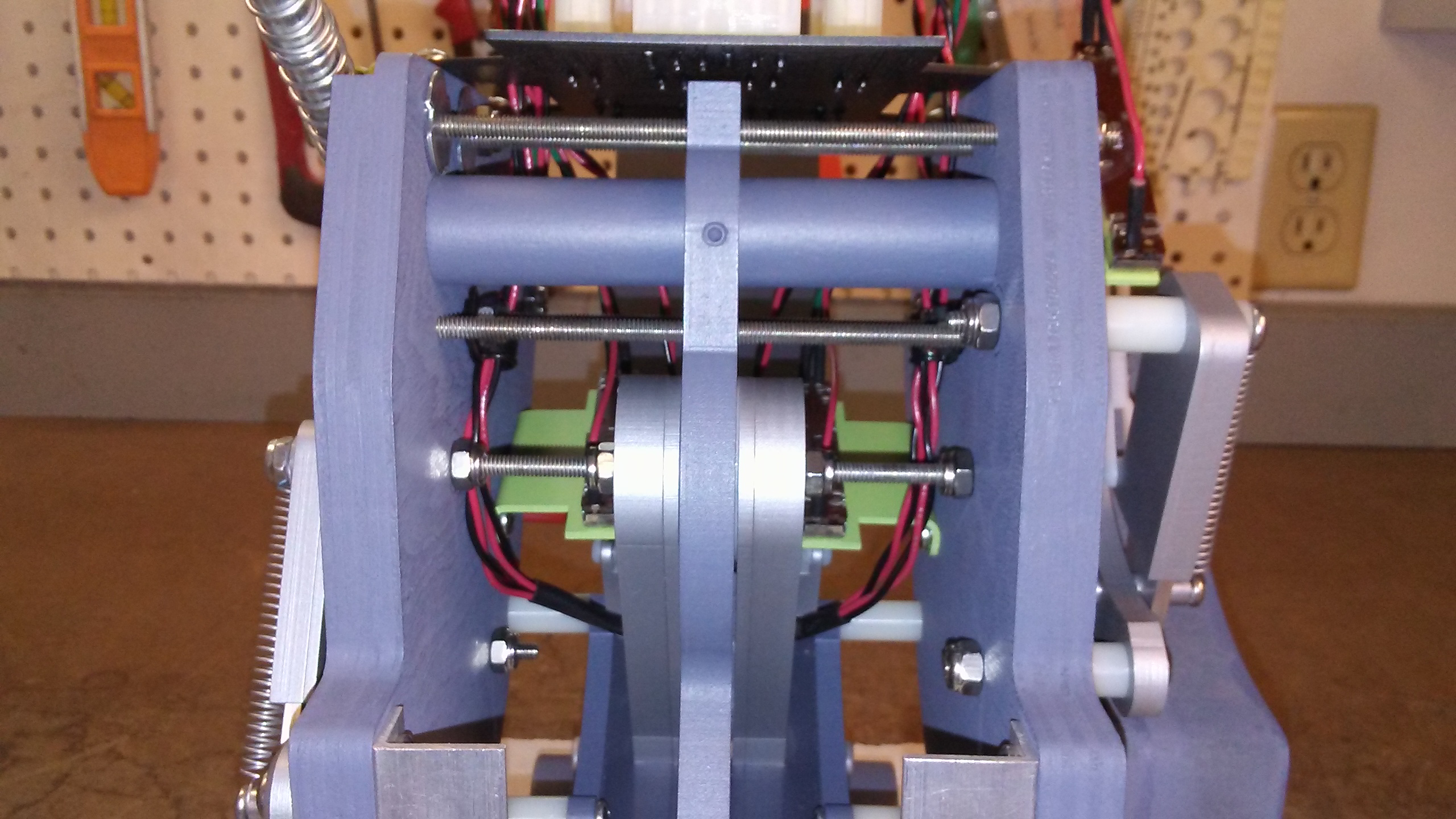
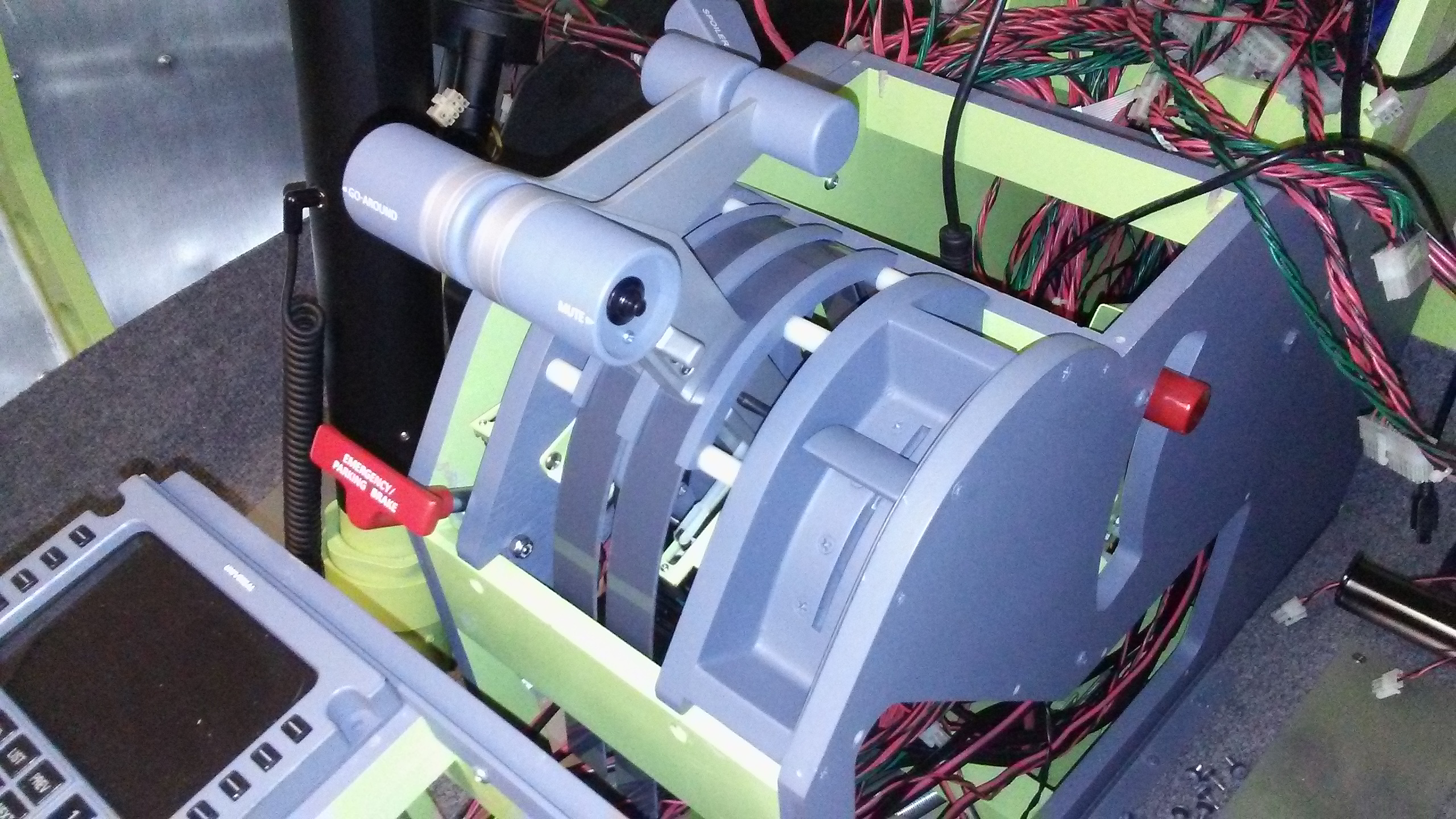
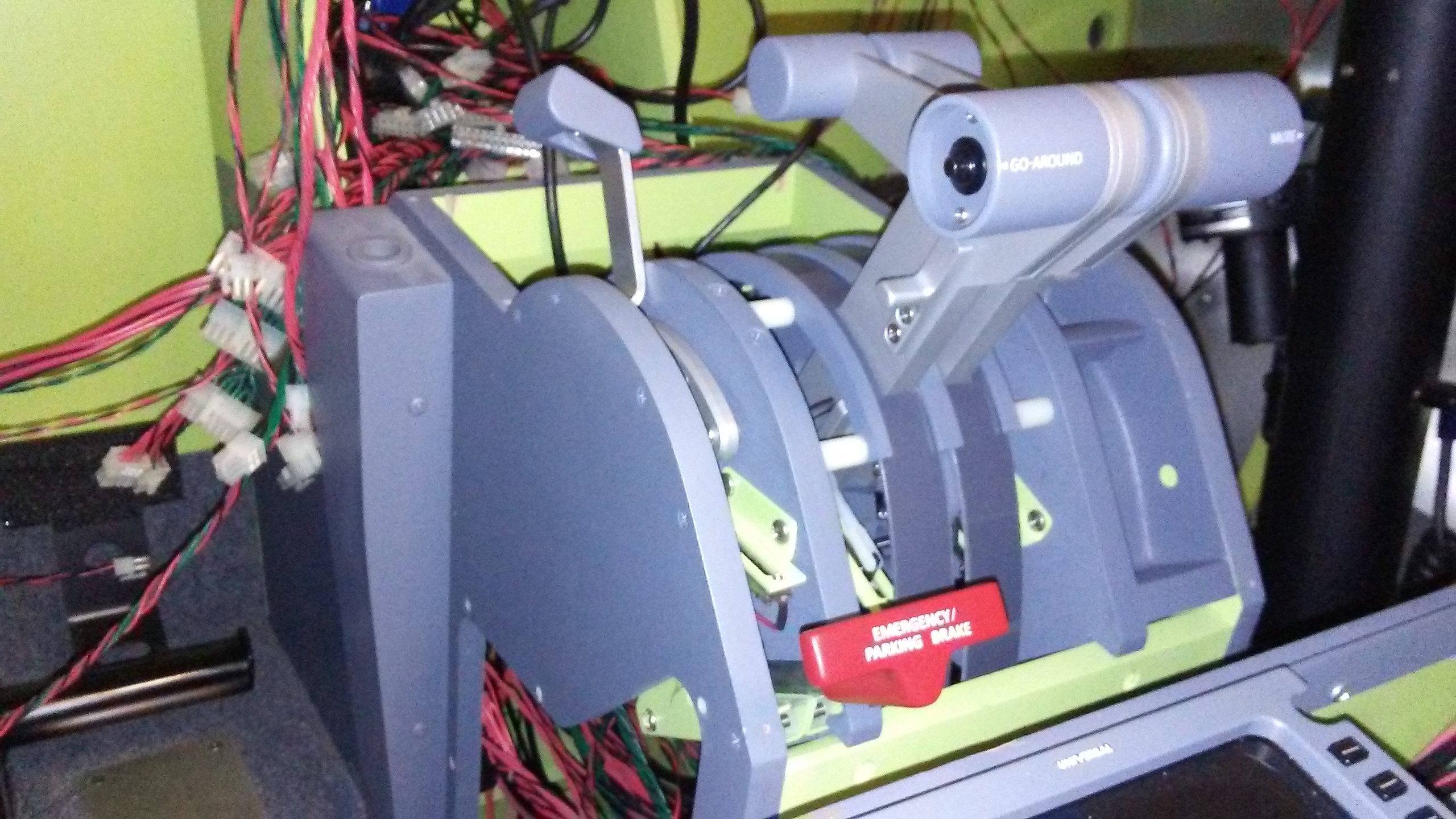
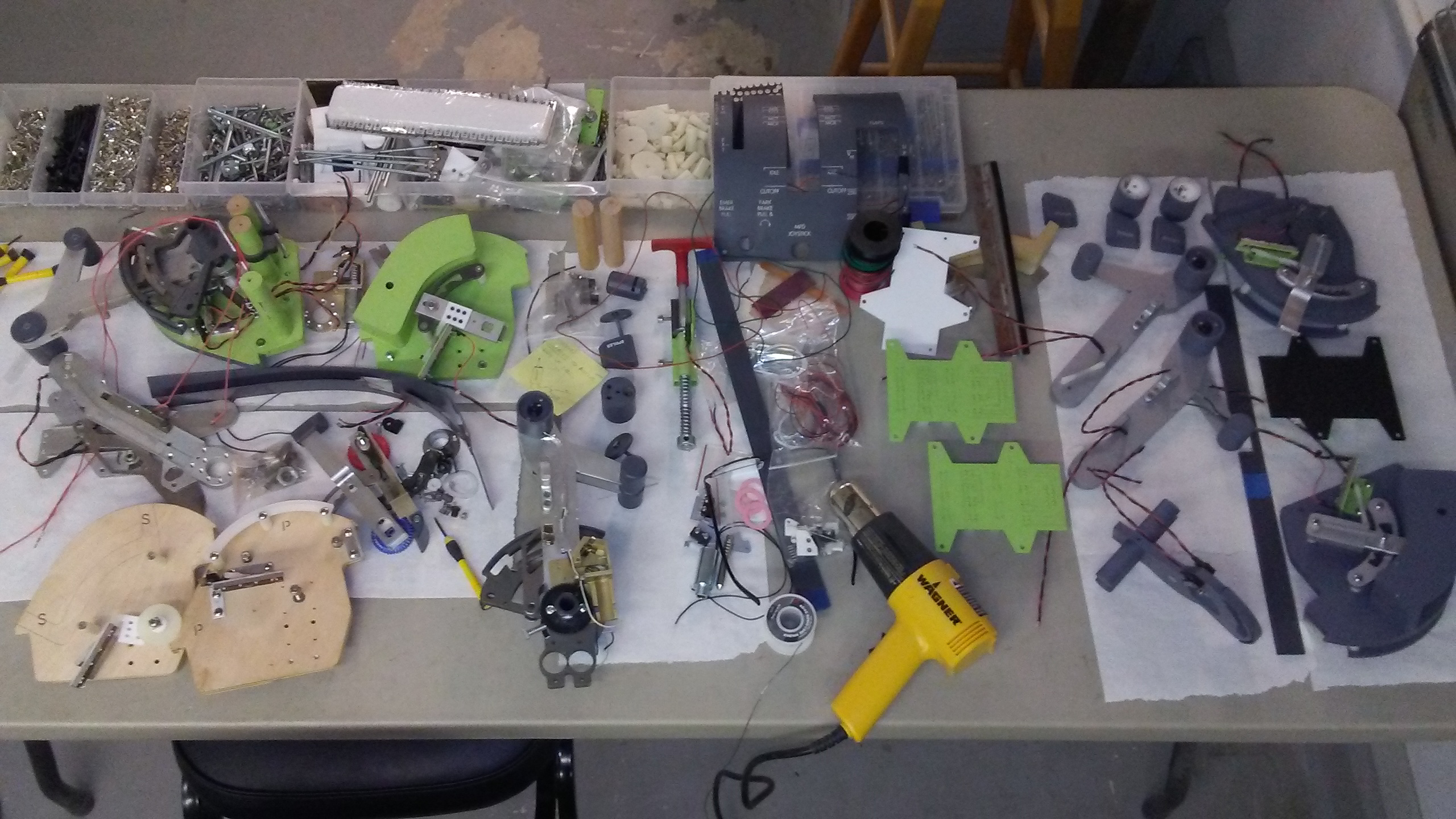
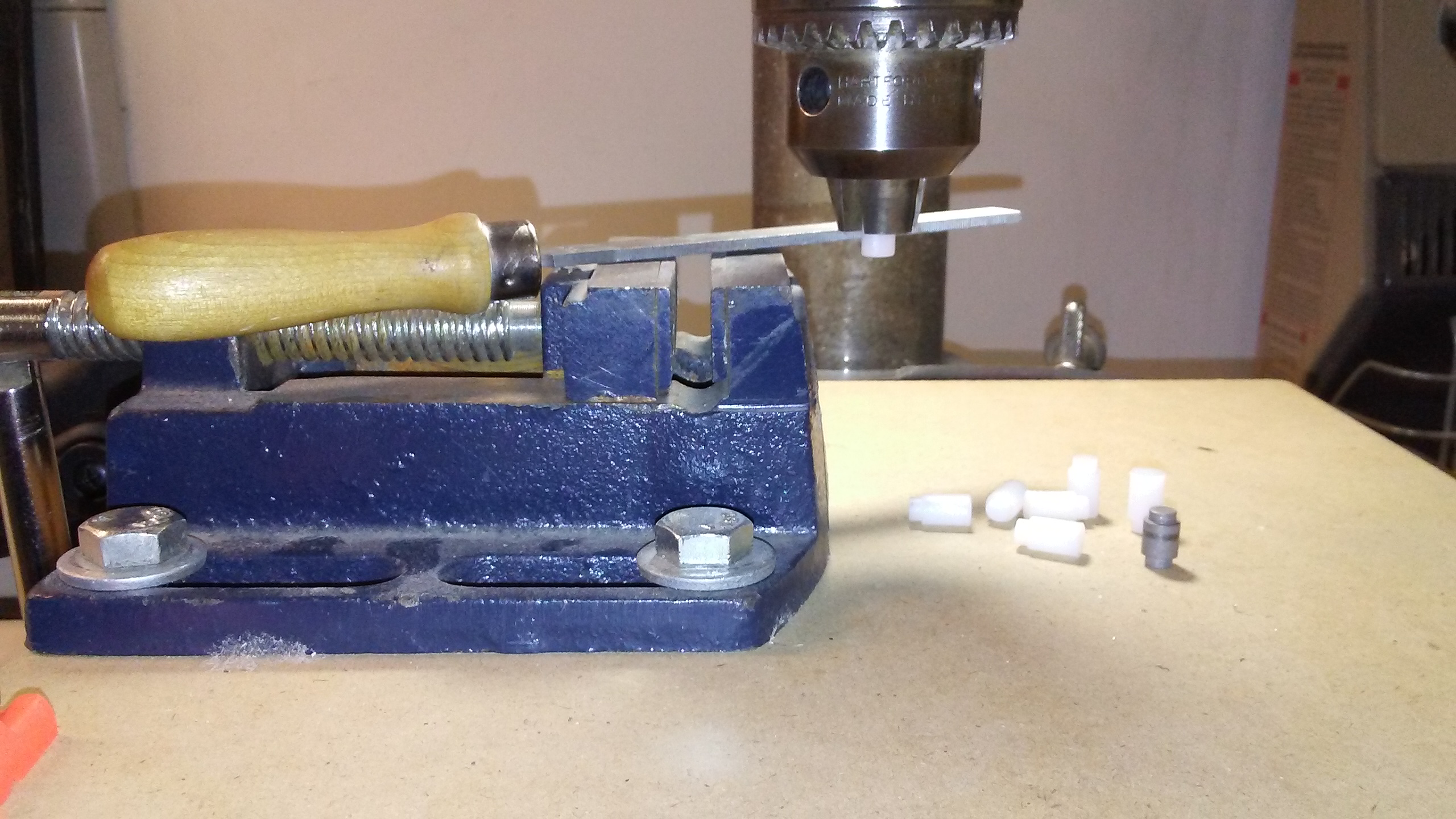
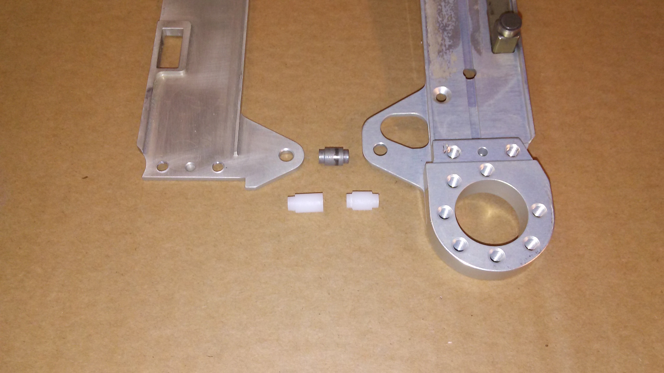
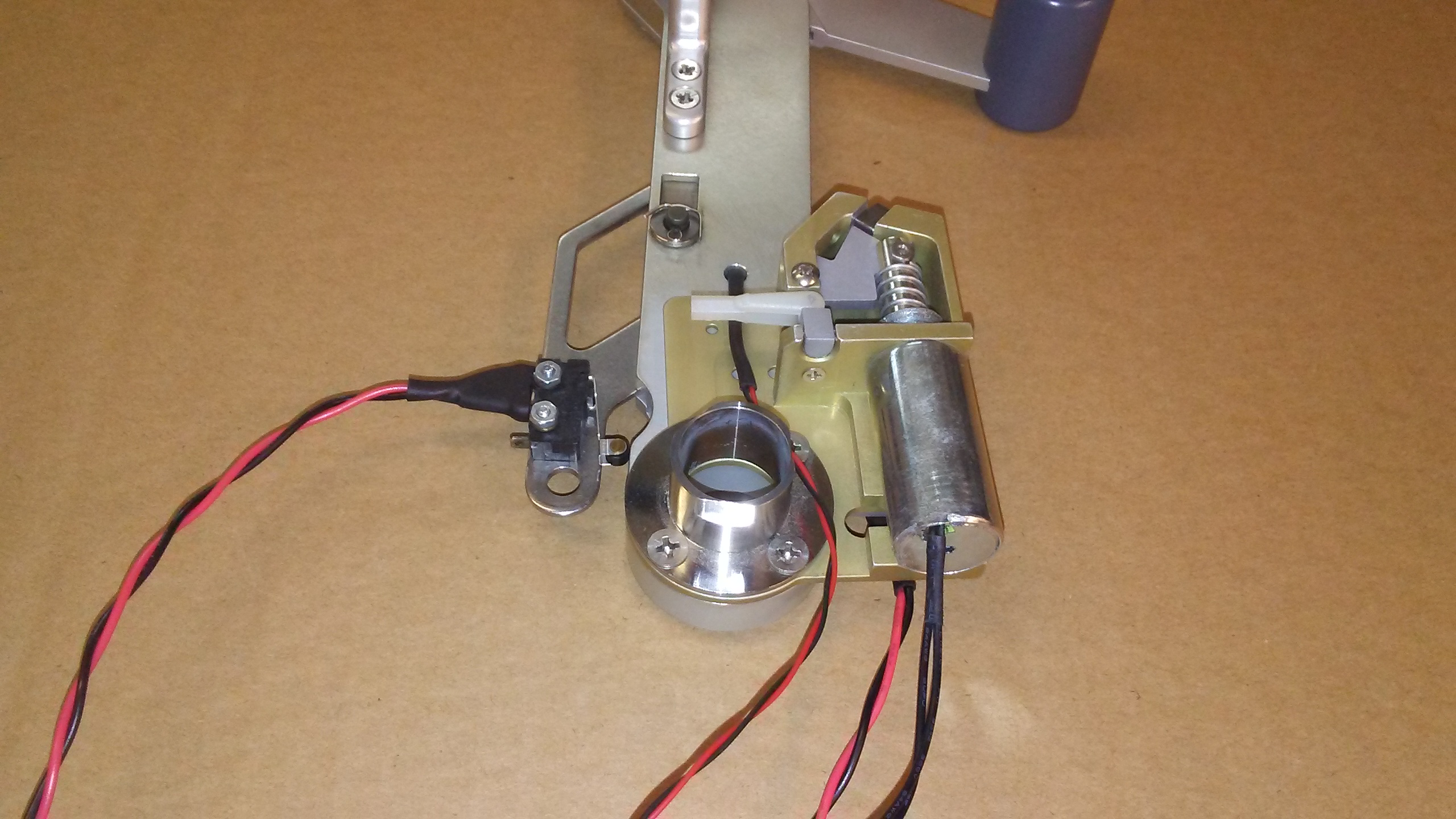
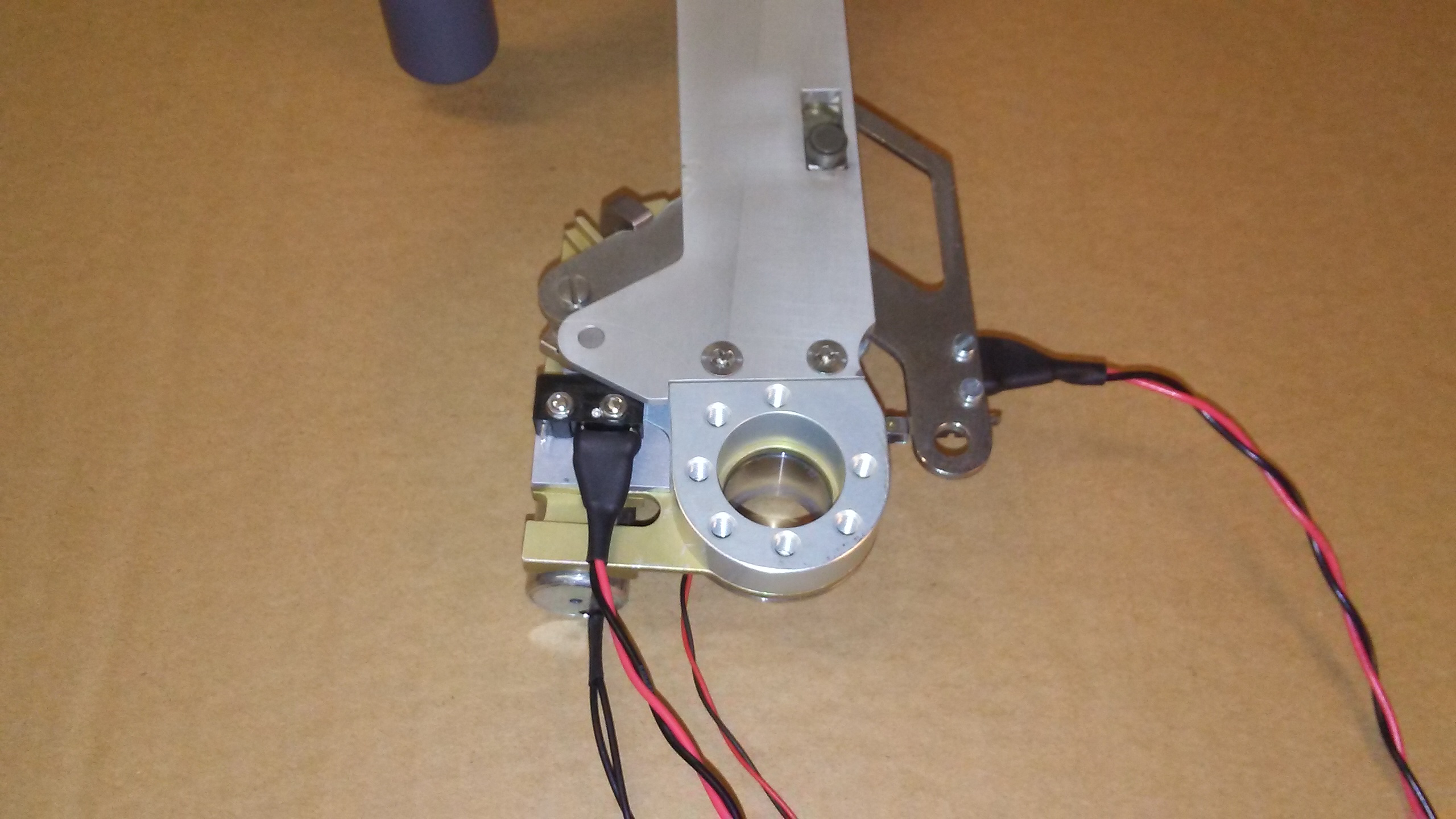
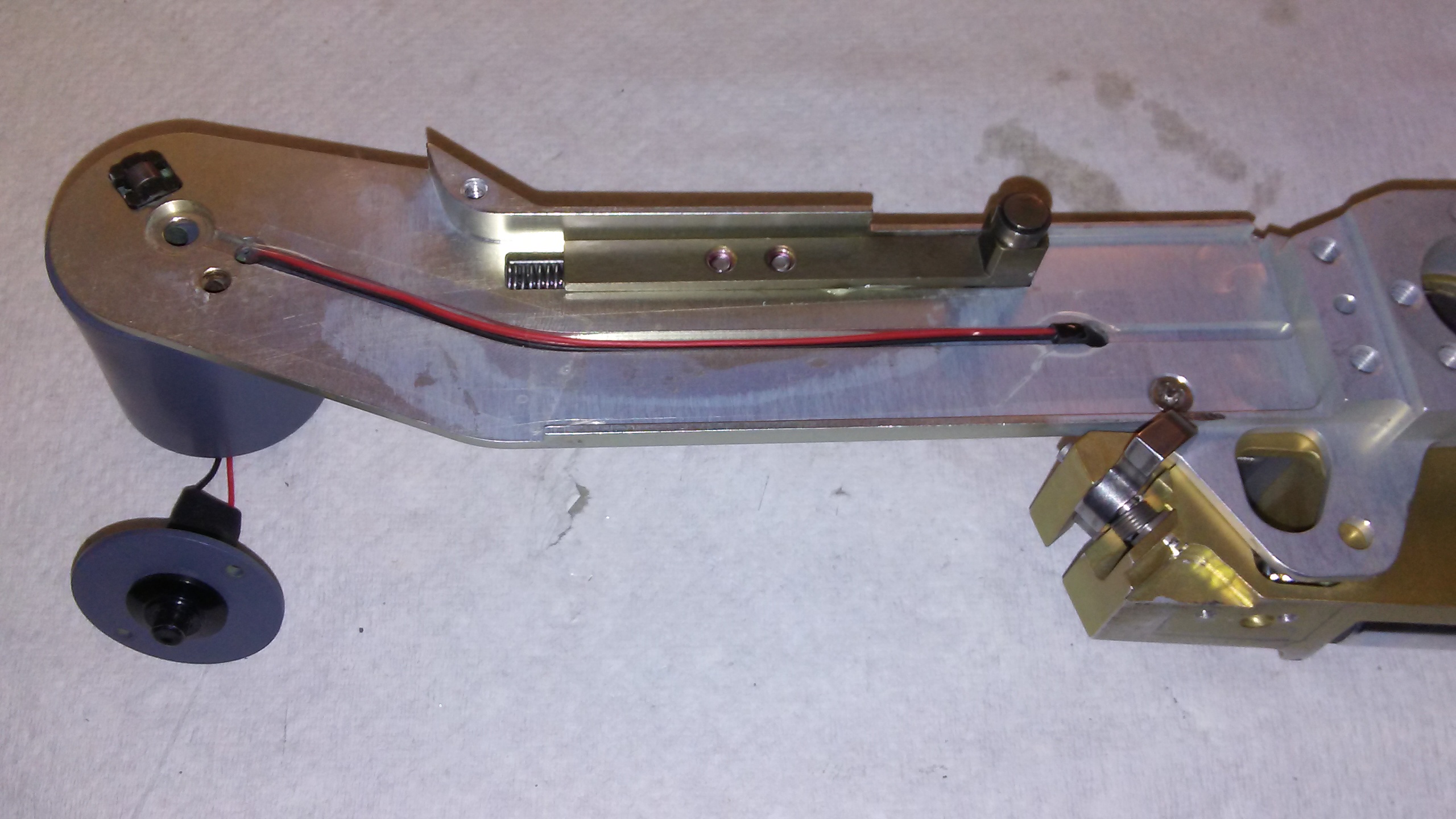
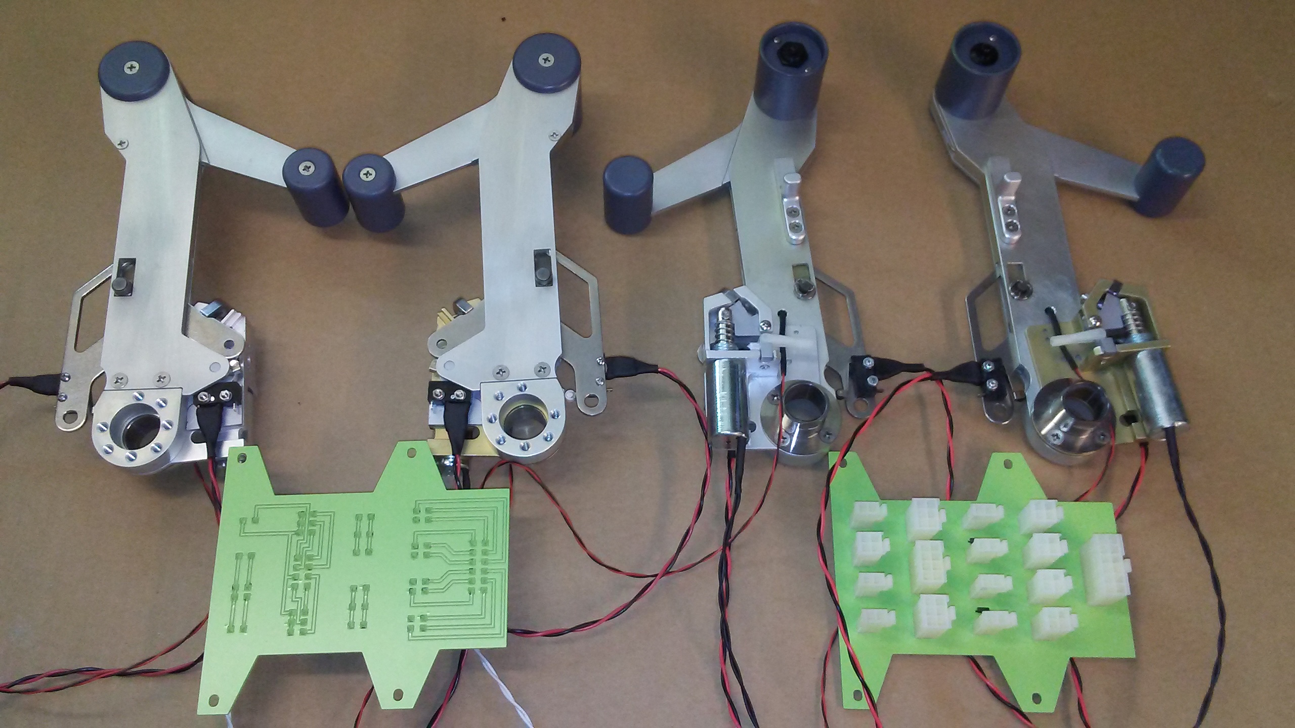
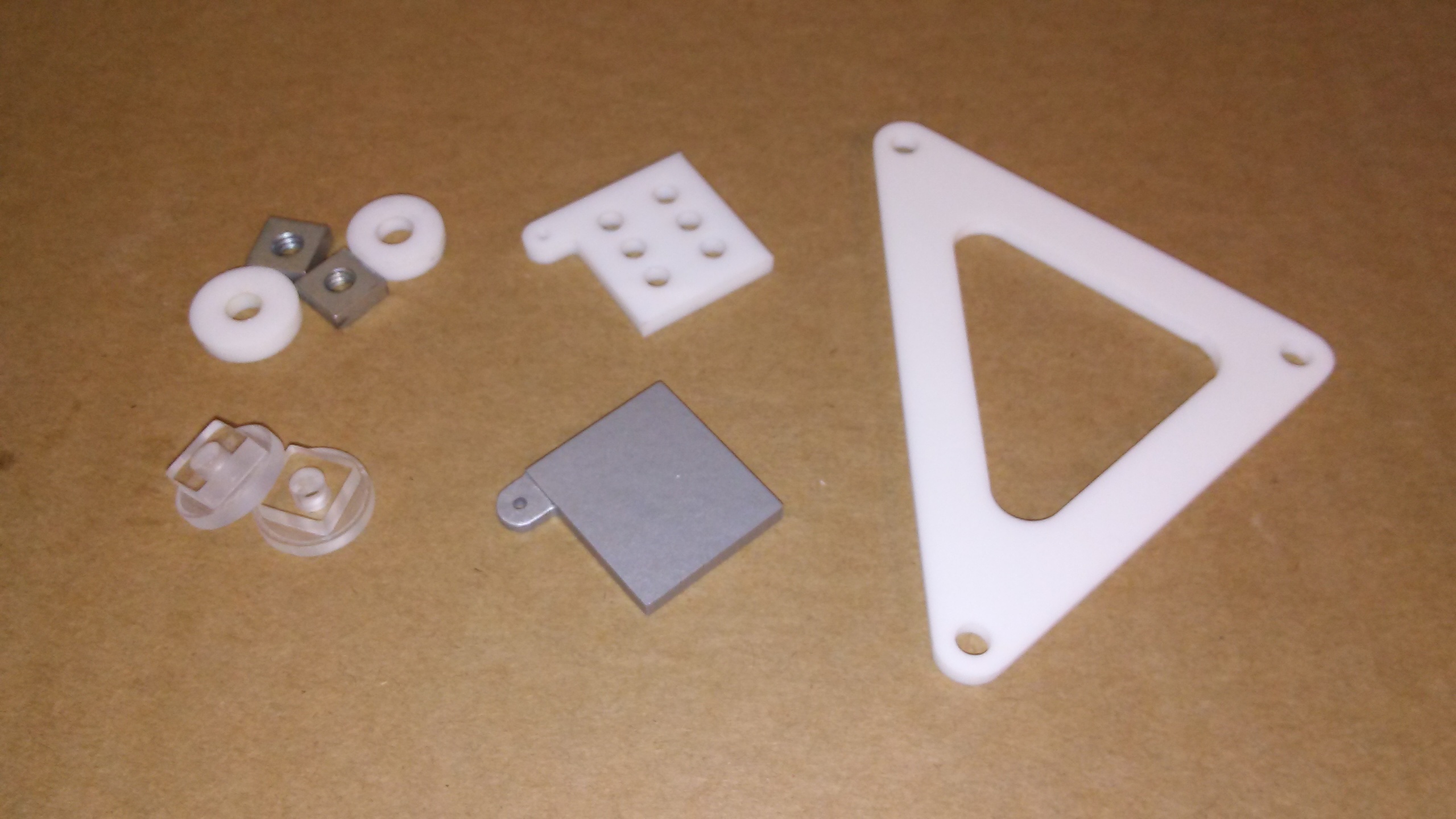
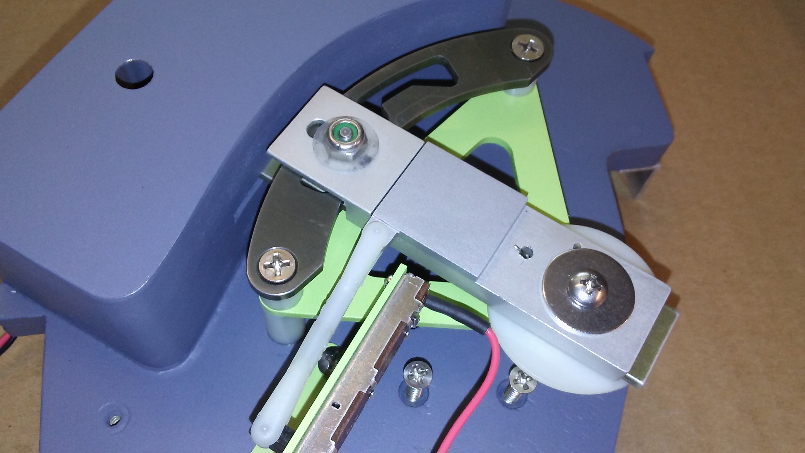
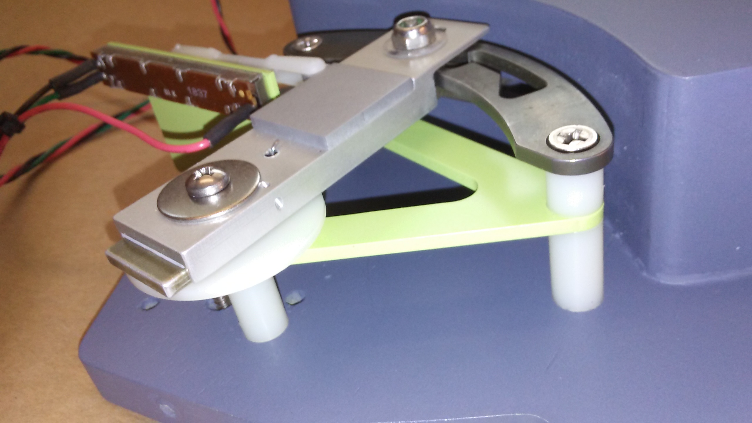
Quick update on the TQ replica progress. This past week I was able to complete five sets of thrust lever knobs. I designed these in the same fashion as the reverser knobs being that it takes four pieces of plastic super glued together to make one knob. This photo shows a couple stages of the process. Note that there is a 8-32 lock nut in the bottom of the ceneter of the knob which serves as the pivot point for the reverser lever. Two of the other holes are for the switch wires, depending if it is the left or right knob. The center hole between the two switch wire holes is for the metal lock pin: Once I have them all super glued together, I use a marker to make guide lines all around the knobs to help highlight high and low marks as I am fine tuning them on the bench grinder. Note the brass inserts that are pressed into place with a hot soldering iron to hold the switch plate in place: This photo is here just to illustrate how I fine tune the knobs with the bench grinder. I gently remove the high spots by rotating the knob in my fingers as the belt passes under the knob. Note the support bar behind the knob. This helps keep the knob square to the belt. Once all the marks are gone in one area, that means move on to another area of the knob so that you don't take too much away in one area: I then hit them all with gray primer and then sand them with a hand block sander. I hit them again with the primer and again hit them with a hand block sander. This process fills in the smaller imperfections. This photo is of the knobs with two coats of Testors Model Master Gunship Gray. Still a little wet which is why they look glossy. They will dry flat like the real knobs: Next I will be working on the reverser levers. The TQ replicas are coming along nicely! Quick update on the TQ replica progress. This past week I was able to complete five sets of thrust lever knobs. I designed these in the same fashion as the reverser knobs being that it takes four pieces of plastic super glued together to make one knob. This photo shows a couple stages of the process. Note that there is a 8-32 lock nut in the bottom of the ceneter of the knob which serves as the pivot point for the reverser lever. Two of the other holes are for the switch wires, depending if it is the left or right knob. The center hole between the two switch wire holes is for the metal lock pin: Once I have them all super glued together, I use a marker to make guide lines all around the knobs to help highlight high and low marks as I am fine tuning them on the bench grinder. Note the brass inserts that are pressed into place with a hot soldering iron to hold the switch plate in place: This photo is here just to illustrate how I fine tune the knobs with the bench grinder. I gently remove the high spots by rotating the knob in my fingers as the belt passes under the knob. Note the support bar behind the knob. This helps keep the knob square to the belt. Once all the marks are gone in one area, that means move on to another area of the knob so that you don't take too much away in one area: I then hit them all with gray primer and then sand them with a hand block sander. I hit them again with the primer and again hit them with a hand block sander. This process fills in the smaller imperfections. This photo is of the knobs with two coats of Testors Model Master Gunship Gray. Still a little wet which is why they look glossy. They will dry flat like the real knobs: Next I will be working on the reverser levers. The TQ replicas are coming along nicely! Another weekly update on the TQ module replica progress. This past week I have completed the reverser levers! I made four sets and man, what a bugger they were. These pieces are milled on both sides which calls for precise placement of the parts on the flip side. The photos below shows the first side has already been cut and is flipped on the CNC. These are all the major parts to the top side of the throttle levers. Notice the Reverser pin in the throttle knob? This is the pin that the reverser lever rides on. For being made of plastic, these pieces are very solid and will not fail during "excited reverser braking." Here are a couple photos of the top end assembled. I thought I would throw in a photo of the real deal throttle knob and reverser lever so that you can compare the replicas to the authentic pieces. As mentioned previously, the only thing that I will not be modeling in with my TQ module replicas is the reverser lock out features. Reason being is that those pieces need to be milled out of harden metal and my CNC is not capable of doing any type of metal. But with that said, for plastic replicas, these things are strong, 100% to scale and look the part! The next step will be to tackle the actual throttle levers! Update on the reverser solenoid "missing link" solution! A while back I decided to take on the "missing link" which enables us to lock out the reversers in flight and during other times depending if certain conditions are met. See earlier post in this thread for additional information. Please note that the following information is for those guys who are lucky enough to have a real set of Lear45 throttles which are made of several different types of metals and include solenoids to lock out the reversers. This function will not be part of the TQ replicas I am currently designing. I have developed a "Missing Link" kit which includes two missing links, two springs, two throttle control attachments, two micro switches, two diodes and some assorted additional hardware. Lets start with the missing link. I designed them to be strong enough that they can be cast plastic and not fail. (Update, they failed and are now made of metal!) For illustration purposes, the metal body that the solenoid is screwed into has been removed from the TQ module. In this photo, the missing link is blocking the reverser linkage from falling into the void. Notice that the piece that my finger is on that I am calling the reverser linkage is pointing directly to the pivot screw? This is how I can put as much pressure as I can muster by pulling on the reverser levers and the linkage will not slip into that void. In this photo, the solenoid has been activated and the missing link has moved out of the way so that the reverser linkage can fall into the void. If that linkage has fallen into that void, this means the reverser levers are pulled all the way back and the reversers have been activated. Also note the new throttle linkage point. When you order your solenoids from the source I point to a couple post earlier, you will note that you will need to open the slot at the top of the solenoid plungers slightly. I did this by using a hand file. Here is a photo of the micro switches and the attachment pieces. Note that I have the arms with the wheels bent up slightly. Also note that you will have to shave down the screws for clearance. The screws on the left have been shaved down. So why do we need ANOTHER micro switch you might ask? Imagine as you first start to pull on the reverser levers, another internal lever moves and will hit this first micro switch. If the conditions are met, as an example, you have weight on wheels and your engines are running, the switch will send a signal to a relay which will in turn send power to the solenoid. The solenoid will pull the missing link out of the void and the reverser linkage will then be allowed to fall into the void. Once the reverser levers are pulled ALL the way back, a second micro switch is selected and that is when the reversers are actually deployed which starts to slow the airplane down. If conditions are not met, as an example, you are at 10,000 feet flying along and you attempt to pull on the reverser levers, the first micro switch will be triggered but because all the conditions are not met, the relay will not apply power to the solenoid, so nothing else happens. Your reversers remain locked out! NOTE: This is exactly how the real Lear45 reverser lockouts work. The only exception is the engine RPM is variable, the further you pull back on the reverser levers, the higher the engine RPMs spool up. We unfortunately don't have control over this but thankfully, the engines spooling up are automatically built into MSFS/P3D and we don't need to worry about modeling this feature. Maybe in the future but for now, there is no real need for this. For the record, one of the only times we are authorized to use the reversers is immediately after a touchdown during the high speed roll out. (Also during some emergency procedures) In other words, the goal is to slow the plane down as quickly and safely as possible. Using the reversers on the ground to "back the plane up" is not authorized although we have all done this in the sim. Snip from DonnyRay: In the real airplane the reverser cycle starts as soon as you hit that first "stop" (the first micro switch), assuming all the proper conditions are met. "The cycle starts....." means that if you hit that micro switch with all prerequisites true the reverser doors immediately go into the DEPLOY operation. When the reverser DOORS hit the fully deployed position THEY operate a micro switch which operates the balk solenoid. THEN you can advance the reverser handle (pull it further up). Pulling further up on the reverser handle increases the throttle setting and spools up the engine. And here's the point: UNLESS the pilot pulls the reverser handle further up the engines don't spool up! Engine speed when reversers are DEPLOYED is not automagic. It's up to the pilot how much, or how little to use. "When would you not use full engine power for reversers?" Any time full reverser power is un-necessary (because reverser operation is an engine stress that is maintenance tracked) or *any time directional control is not assured*. Landing on ice, on a water covered runway, right at the max crosswind component, with one engine shut down, or with rudder control problems, are all examples when pilot judgement is needed as to the amount of reverser power to use. In fact, reversers can be used to regain directional control on ice but it requires action without hesitation. So with all that said, here are a couple photos of where the first micro switch will be installed. Right click on the photo and select "View Photo" to blow it up. Here the internal reverser lever is pressing against the wheel of the micro switch. If you have a real set of TQ levers and are interested in this update, just email me and I will work to get you a kit in hand. If you have any questions, just ask! Another weekly update on the TQ module replica progress. This past week I have completed the reverser levers! I made four sets and man, what a bugger they were. These pieces are milled on both sides which calls for precise placement of the parts on the flip side. The photos below shows the first side has already been cut and is flipped on the CNC. These are all the major parts to the top side of the throttle levers. Notice the Reverser pin in the throttle knob? This is the pin that the reverser lever rides on. For being made of plastic, these pieces are very solid and will not fail during "excited reverser braking." Here are a couple photos of the top end assembled. I thought I would throw in a photo of the real deal throttle knob and reverser lever so that you can compare the replicas to the authentic pieces. As mentioned previously, the only thing that I will not be modeling in with my TQ module replicas is the reverser lock out features. Reason being is that those pieces need to be milled out of harden metal and my CNC is not capable of doing any type of metal. But with that said, for plastic replicas, these things are strong, 100% to scale and look the part! The next step will be to tackle the actual throttle levers! Update on the reverser solenoid "missing link" solution! A while back I decided to take on the "missing link" which enables us to lock out the reversers in flight and during other times depending if certain conditions are met. See earlier post in this thread for additional information. Please note that the following information is for those guys who are lucky enough to have a real set of Lear45 throttles which are made of several different types of metals and include solenoids to lock out the reversers. This function will not be part of the TQ replicas I am currently designing. I have developed a "Missing Link" kit which includes two missing links, two springs, two throttle control attachments, two micro switches, two diodes and some assorted additional hardware. Lets start with the missing link. I designed them to be strong enough that they can be cast plastic and not fail. (Update, they failed and are now made of metal!) For illustration purposes, the metal body that the solenoid is screwed into has been removed from the TQ module. In this photo, the missing link is blocking the reverser linkage from falling into the void. Notice that the piece that my finger is on that I am calling the reverser linkage is pointing directly to the pivot screw? This is how I can put as much pressure as I can muster by pulling on the reverser levers and the linkage will not slip into that void. In this photo, the solenoid has been activated and the missing link has moved out of the way so that the reverser linkage can fall into the void. If that linkage has fallen into that void, this means the reverser levers are pulled all the way back and the reversers have been activated. Also note the new throttle linkage point. When you order your solenoids from the source I point to a couple post earlier, you will note that you will need to open the slot at the top of the solenoid plungers slightly. I did this by using a hand file. Here is a photo of the micro switches and the attachment pieces. Note that I have the arms with the wheels bent up slightly. Also note that you will have to shave down the screws for clearance. The screws on the left have been shaved down. So why do we need ANOTHER micro switch you might ask? Imagine as you first start to pull on the reverser levers, another internal lever moves and will hit this first micro switch. If the conditions are met, as an example, you have weight on wheels and your engines are running, the switch will send a signal to a relay which will in turn send power to the solenoid. The solenoid will pull the missing link out of the void and the reverser linkage will then be allowed to fall into the void. Once the reverser levers are pulled ALL the way back, a second micro switch is selected and that is when the reversers are actually deployed which starts to slow the airplane down. If conditions are not met, as an example, you are at 10,000 feet flying along and you attempt to pull on the reverser levers, the first micro switch will be triggered but because all the conditions are not met, the relay will not apply power to the solenoid, so nothing else happens. Your reversers remain locked out! NOTE: This is exactly how the real Lear45 reverser lockouts work. The only exception is the engine RPM is variable, the further you pull back on the reverser levers, the higher the engine RPMs spool up. We unfortunately don't have control over this but thankfully, the engines spooling up are automatically built into MSFS/P3D and we don't need to worry about modeling this feature. Maybe in the future but for now, there is no real need for this. For the record, one of the only times we are authorized to use the reversers is immediately after a touchdown during the high speed roll out. (Also during some emergency procedures) In other words, the goal is to slow the plane down as quickly and safely as possible. Using the reversers on the ground to "back the plane up" is not authorized although we have all done this in the sim. Snip from DonnyRay: In the real airplane the reverser cycle starts as soon as you hit that first "stop" (the first micro switch), assuming all the proper conditions are met. "The cycle starts....." means that if you hit that micro switch with all prerequisites true the reverser doors immediately go into the DEPLOY operation. When the reverser DOORS hit the fully deployed position THEY operate a micro switch which operates the balk solenoid. THEN you can advance the reverser handle (pull it further up). Pulling further up on the reverser handle increases the throttle setting and spools up the engine. And here's the point: UNLESS the pilot pulls the reverser handle further up the engines don't spool up! Engine speed when reversers are DEPLOYED is not automagic. It's up to the pilot how much, or how little to use. "When would you not use full engine power for reversers?" Any time full reverser power is un-necessary (because reverser operation is an engine stress that is maintenance tracked) or *any time directional control is not assured*. Landing on ice, on a water covered runway, right at the max crosswind component, with one engine shut down, or with rudder control problems, are all examples when pilot judgement is needed as to the amount of reverser power to use. In fact, reversers can be used to regain directional control on ice but it requires action without hesitation. So with all that said, here are a couple photos of where the first micro switch will be installed. Right click on the photo and select "View Photo" to blow it up. Here the internal reverser lever is pressing against the wheel of the micro switch. If you have a real set of TQ levers and are interested in this update, just email me and I will work to get you a kit in hand. If you have any questions, just ask! Hey guys! We are getting closer to having the TQ module complete! Today I finished up with the center spline piece that rest between the two throttle levers. This piece is like the back bone of the TQ module where everything rides on or against it. These pieces will control the rotation point, the throttle detents, fuel cut off and also have the inside dust cover slider channels. Remember, these are replicas and are not built like the real Lear45 throttles but sure are gonna look like them and move like them with the exception of the reverser lock out features. Here are a couple photos of an early test fit of the center spline piece with some dust covers installed! Another photos of the TQ module turned upside down. Just like my TQ Module that uses the real parts, I am using four 8-32 threaded rods and two wooden dowels to bring everything together. Here is a photo of four center splines painted and assembled. If you look closely, you will notice that I am using a 8-32 set screw to precisely hold the wooden dowel in place. The micro switches that you see are the fuel cut off switches that the throttle levers will rest against when they are in the CUT OFF position. So now we are getting down to the fun stuff........the throttle levers themselves! Keep an eye out for them! Hey guys! We are getting closer to having the TQ module complete! Today I finished up with the center spline piece that rest between the two throttle levers. This piece is like the back bone of the TQ module where everything rides on or against it. These pieces will control the rotation point, the throttle detents, fuel cut off and also have the inside dust cover slider channels. Remember, these are replicas and are not built like the real Lear45 throttles but sure are gonna look like them and move like them with the exception of the reverser lock out features. Here are a couple photos of an early test fit of the center spline piece with some dust covers installed! Another photos of the TQ module turned upside down. Just like my TQ Module that uses the real parts, I am using four 8-32 threaded rods and two wooden dowels to bring everything together. Here is a photo of four center splines painted and assembled. If you look closely, you will notice that I am using a 8-32 set screw to precisely hold the wooden dowel in place. The micro switches that you see are the fuel cut off switches that the throttle levers will rest against when they are in the CUT OFF position. So now we are getting down to the fun stuff........the throttle levers themselves! Keep an eye out for them! As promised, here are the throttle levers! They will look exactly like the real throttle levers and operate exactly like the real deal with the exception of the reverser lockouts. The only way to properly model the TQ module 100% is to build the internal mechanical pieces using harden metals. Aluminum will not work, it is too soft. With that said, let me explain what I was able to model. First, you will notice the wire channel for the knob switches and the the reverser switches. On the other side of the lever main body is the detent lever mechanism slide. This is operated using a small compression spring. I am also using brass inserts to help hold the throttle lever cover to the throttle lever main body. See photo below: Here is the complete set of four with the reverser switches and detent slides in place: This is the detent lever and internal slide mounted together with the spring for illustration purposes: A quick test fit of the throttle lever with the center splines and the reverser levers. Everything is looking good! Last but not least, here are all the throttle lever covers completed and painted, ready to go! Next week I will be working on the laser engraving of the throttle knobs and Spoiler knob. Additionally, I am working on what I am calling a "Wire Management Board" that will mount to the bottom of the TQ module. The basic idea is that everything from the TQ module will plug into this board and it will act as a signal organizer. The signals will be grouped appropriately and sent to their proper interface cards. More on this later once I develop a prototype. As promised, here are the throttle levers! They will look exactly like the real throttle levers and operate exactly like the real deal with the exception of the reverser lockouts. The only way to properly model the TQ module 100% is to build the internal mechanical pieces using harden metals. Aluminum will not work, it is too soft. With that said, let me explain what I was able to model. First, you will notice the wire channel for the knob switches and the the reverser switches. On the other side of the lever main body is the detent lever mechanism slide. This is operated using a small compression spring. I am also using brass inserts to help hold the throttle lever cover to the throttle lever main body. See photo below: Here is the complete set of four with the reverser switches and detent slides in place: This is the detent lever and internal slide mounted together with the spring for illustration purposes: A quick test fit of the throttle lever with the center splines and the reverser levers. Everything is looking good! Last but not least, here are all the throttle lever covers completed and painted, ready to go! Next week I will be working on the laser engraving of the throttle knobs and Spoiler knob. Additionally, I am working on what I am calling a "Wire Management Board" that will mount to the bottom of the TQ module. The basic idea is that everything from the TQ module will plug into this board and it will act as a signal organizer. The signals will be grouped appropriately and sent to their proper interface cards. More on this later once I develop a prototype. I am getting really close to having a couple sets of replica TQ modules completed! Recently I have finished making all the parts on the CNC, sanded everything down and painted all the parts. I also sent off the throttle knobs and the spoiler knobs to the laser shop for engraving. Those items should be ready in the next day or two. Here is a photo of the majority of the parts laid out on an assembly table! This is the Wire Management Board I mentioned in the last post. Because there are wires coming from every nook and cranny of the TQ module and on top of that going to at least three different interface cards, I designed this so that everything from the TQ module can plug into this board and then the signals can be grouped together accordingly within. The First row at the top will handle the flaps, throttle 1, throttle 2 and the spoilers grouped together and leaving the Wire Management Board. This group will be routed to a Leo Bodnar card or similar type interface card that handles potentiometers. The second row from the top will handle the flaps, throttle 1, throttle 2 and spoiler potentiometers coming into the board. The third row from the top is reserved for the reverser lockout solenoids. These will be utilized in the throttle quadrants that have real TQ parts. (Notice that there is a built in 470 uF capacitors to capture the electromagnetic energy from the solenoids.) These lines will route back to the left FDS relay card and the right FDS relay card. They will not be used in the replica TQ modules. The second row from the bottom will handle the left and right fuel cut off switches, the left and the right reverser switches and the left and light reverse lockout switches. These signals will be routed back to the FDS SYS card or similar interface card. The last row at the bottom is for the MUTE and the GO AROUND buttons on the end of the throttle knobs. They will route back to the FGC Sub Module because these two functions are part of the AP system. Also note that there is an additional plug for the Parking Brake that is routed back to the second row. I will post up some more photos of this once I get them wired up. It will make more sense at that point. I am getting really close to having a couple sets of replica TQ modules completed! Recently I have finished making all the parts on the CNC, sanded everything down and painted all the parts. I also sent off the throttle knobs and the spoiler knobs to the laser shop for engraving. Those items should be ready in the next day or two. Here is a photo of the majority of the parts laid out on an assembly table! This is the Wire Management Board I mentioned in the last post. Because there are wires coming from every nook and cranny of the TQ module and on top of that going to at least three different interface cards, I designed this so that everything from the TQ module can plug into this board and then the signals can be grouped together accordingly within. The First row at the top will handle the flaps, throttle 1, throttle 2 and the spoilers grouped together and leaving the Wire Management Board. This group will be routed to a Leo Bodnar card or similar type interface card that handles potentiometers. The second row from the top will handle the flaps, throttle 1, throttle 2 and spoiler potentiometers coming into the board. The third row from the top is reserved for the reverser lockout solenoids. These will be utilized in the throttle quadrants that have real TQ parts. (Notice that there is a built in 470 uF capacitors to capture the electromagnetic energy from the solenoids.) These lines will route back to the left FDS relay card and the right FDS relay card. They will not be used in the replica TQ modules. The second row from the bottom will handle the left and right fuel cut off switches, the left and the right reverser switches and the left and light reverse lockout switches. These signals will be routed back to the FDS SYS card or similar interface card. The last row at the bottom is for the MUTE and the GO AROUND buttons on the end of the throttle knobs. They will route back to the FGC Sub Module because these two functions are part of the AP system. Also note that there is an additional plug for the Parking Brake that is routed back to the second row. I will post up some more photos of this once I get them wired up. It will make more sense at that point. Great addition to the product line up! This is one of those must have items in your sim . . considering how much you interact with the throttle quadrant! Great addition to the product line up! This is one of those must have items in your sim . . considering how much you interact with the throttle quadrant! Now couple thousand screws and almost done... Ron, I can't imagine how tight (read: jammed) all pieces are gonna be inside and most of them are moving pieces! That is just plain insanity. As I stated before, this is one of the most sophisticated and complex part in the simulator. A "must have" part tho! Now couple thousand screws and almost done... Ron, I can't imagine how tight (read: jammed) all pieces are gonna be inside and most of them are moving pieces! That is just plain insanity. As I stated before, this is one of the most sophisticated and complex part in the simulator. A "must have" part tho! Thanks guys! I am finally at the point where I can say that the TQ module Replica is nearing completion. But first I want to share a few photos of some of the work leading up to the complete TQ module. This is the completed Wire Management Board with the plugs soldered in place and painted. This board will mount to the bottom of the TQ module. Keep in mind that this board seen below is universal for both the replicas and the TQ module that uses the real parts: This is the wire diagram that shows in detail where each of the plugs and pins go to. Right click to enlarge: The throttle knobs and spoiler knobs came back from the laser shop and look great! I did have to touch them up with brilliant white caulking. By rubbing the caulking into the engraving lettering grooves, it brightens up the lettering the way we would expect them to be: Now that I have all the parts of the TQ module within arms length, I am finally ready to start assembly. In this photo, I am insuring that the wires are lined up properly in the center channel. I also added some Lithium grease to the internal slide and the spring for smoother operation: Here I am getting ready to screw the throttle knob switch cap in place. I have about three inches of extra 28 gauge wire so that the switch caps can be removed later if need be. It might be hard to tell, but I switched to 22 gauge wire about half way down the lever so that the wires coming out of the levers are stronger going to the Wire Management Board: I used several rods and lock nuts to bring everything together. This ended up being a tedious process because if I tighten up one nut, something elsewhere might get loose. This is a good thing because there are several adjustment points to insure that the throttle levers are set to the right amount of resistance. Check out the completed unit! Right click on any of these photos to enlarge them: Straight on view: Back side view: Bottom side view of the Wire Management Board. The three empty plugs will be for the wiring harnesses that will head back to the interface cards. This is a close up view of some of the internal components inside the TQ module. Note that this photo is upside down: Another close look at the internal parts, rods and lock nuts: I did a test fit of the TQ Module replica in my TQ pedestal. Of course it fits! The screws on the parking brake assembly need to be shaved down a little but it fits! Test fit view from the left. I love it when it all comes together! So at this point the TQ Module replicas are nearing completion. I have four sets. Two are taken and two are currently available. The initial price for a TQ module replica will be $1,250. This price does not include the future light plate which will be around $295. I have made additional parts for several future sets as the demand for these increase. If interested in a set, you can post here or email me! Thanks guys! I am finally at the point where I can say that the TQ module Replica is nearing completion. But first I want to share a few photos of some of the work leading up to the complete TQ module. This is the completed Wire Management Board with the plugs soldered in place and painted. This board will mount to the bottom of the TQ module. Keep in mind that this board seen below is universal for both the replicas and the TQ module that uses the real parts: This is the wire diagram that shows in detail where each of the plugs and pins go to. Right click to enlarge: The throttle knobs and spoiler knobs came back from the laser shop and look great! I did have to touch them up with brilliant white caulking. By rubbing the caulking into the engraving lettering grooves, it brightens up the lettering the way we would expect them to be: Now that I have all the parts of the TQ module within arms length, I am finally ready to start assembly. In this photo, I am insuring that the wires are lined up properly in the center channel. I also added some Lithium grease to the internal slide and the spring for smoother operation: Here I am getting ready to screw the throttle knob switch cap in place. I have about three inches of extra 28 gauge wire so that the switch caps can be removed later if need be. It might be hard to tell, but I switched to 22 gauge wire about half way down the lever so that the wires coming out of the levers are stronger going to the Wire Management Board: I used several rods and lock nuts to bring everything together. This ended up being a tedious process because if I tighten up one nut, something elsewhere might get loose. This is a good thing because there are several adjustment points to insure that the throttle levers are set to the right amount of resistance. Check out the completed unit! Right click on any of these photos to enlarge them: Straight on view: Back side view: Bottom side view of the Wire Management Board. The three empty plugs will be for the wiring harnesses that will head back to the interface cards. This is a close up view of some of the internal components inside the TQ module. Note that this photo is upside down: Another close look at the internal parts, rods and lock nuts: I did a test fit of the TQ Module replica in my TQ pedestal. Of course it fits! The screws on the parking brake assembly need to be shaved down a little but it fits! Test fit view from the left. I love it when it all comes together! So at this point the TQ Module replicas are nearing completion. I have four sets. Two are taken and two are currently available. The initial price for a TQ module replica will be $1,250. This price does not include the future light plate which will be around $295. I have made additional parts for several future sets as the demand for these increase. If interested in a set, you can post here or email me! Hey guys, Now that I have a good handle on the TQ module replicas, it is time to get to work on a couple sets that have real TQ parts. So the next couple updates in this thread will cover the rebuilding of my TQ module to include the new reverse lockout functions (and some other minor updates) and the complete build up of Mark Speechley's TQ module. This gives me a great opportunity to add some more fine details and tutorials on how to build up your TQ module with real parts to make it flightsim worthy! Has that term been coined yet? "Flightsim worthy" So to get started, here is an overall picture of actually three TQ modules. The one in pieces on the far right is a replica waiting on a parking brake assembly from Shane. Does this table look like fun or what? I like to start from the inside and work my way out of the TQs. The center spline has four holes that need to be opened up slightly to 11/64th" in order to accommodate 8-32 threaded rods. This metal is fairly soft and easy to open up with the help of a drill press: The next thing that has to be done is to tap a larger hole into the metal tube for the set screw. It is a metric size so be mindful not to use the wrong tap when creating the threads in the tube. There is already a smaller hole in the center of the metal tube so figuring out where center is has already been done: The Go-Around and Mute switches are complete. There are two important things to keep in mind here. First, you need to use 28 gauge stranded wire. "28 gauge" so that the two wires fit inside the internal channel of the throttle levers. "Stranded" so that the wire is easier to solder and the wire bends easily without breaking. The second thing to keep in mind is to make sure you use shrink tube at the soldering joints at the switch and where the wires come out of the lever. Any moving parts that also have wires need extra special attention, otherwise, in short time, the wires will fail at the solder joints or anywhere there is a lot of bending going on. I will cover this topic more as the need arises: Mark's TQ set was missing what I call the reverser lever pins. The real ones are made of aluminum but these can be replaced with cast plastic because there is very little force being applied to them. Here is a photo of the cast plastic replica in place with a real pin setting on the bench: I made these with the use of the CNC and the drill press. (A lathe machine would have been a little easier!) The CNC cuts out the basic shape and mills one end. The other end has to be completed in the drill press and a shaping tool, like a sharp file: The end results (Ha...no pun intended!) are as good as the real thing. Once they are painted with a metal finish, they will look perfect: I have assembled one of the throttle levers to my TQ module and all looks and works great! Remember, the main reason for me to pull my TQ module completely apart was to update it with the reverse lockout solenoids, missing link and switch. These next two photos show the new parts in detail: Note the extra shrink wrap protection at the soldering joints on both switches and on the 28 gauge wire coming out of the lever? Also note the new throttle rod attachment point clevis. This had to be added to make room for the pivot point for the missing link piece. This next photo show the back side of the right throttle lever. The photo shows the addition of the new reverser lockout switch to the left. If you look closely, you can see where the reverser lever pin is installed just above the switch. CAUTION: The TQ module, pedal assemblies and the columns are the only three areas in the Lear45 sim that have moving parts AND also have wires coming from those parts. Always use extra precaution in areas like this so that the wires do not bend at the soldering joints or are pinched. I will continue to give weekly updates on this thread until they are complete! Hey guys, Now that I have a good handle on the TQ module replicas, it is time to get to work on a couple sets that have real TQ parts. So the next couple updates in this thread will cover the rebuilding of my TQ module to include the new reverse lockout functions (and some other minor updates) and the complete build up of Mark Speechley's TQ module. This gives me a great opportunity to add some more fine details and tutorials on how to build up your TQ module with real parts to make it flightsim worthy! Has that term been coined yet? "Flightsim worthy" So to get started, here is an overall picture of actually three TQ modules. The one in pieces on the far right is a replica waiting on a parking brake assembly from Shane. Does this table look like fun or what? I like to start from the inside and work my way out of the TQs. The center spline has four holes that need to be opened up slightly to 11/64th" in order to accommodate 8-32 threaded rods. This metal is fairly soft and easy to open up with the help of a drill press: The next thing that has to be done is to tap a larger hole into the metal tube for the set screw. It is a metric size so be mindful not to use the wrong tap when creating the threads in the tube. There is already a smaller hole in the center of the metal tube so figuring out where center is has already been done: The Go-Around and Mute switches are complete. There are two important things to keep in mind here. First, you need to use 28 gauge stranded wire. "28 gauge" so that the two wires fit inside the internal channel of the throttle levers. "Stranded" so that the wire is easier to solder and the wire bends easily without breaking. The second thing to keep in mind is to make sure you use shrink tube at the soldering joints at the switch and where the wires come out of the lever. Any moving parts that also have wires need extra special attention, otherwise, in short time, the wires will fail at the solder joints or anywhere there is a lot of bending going on. I will cover this topic more as the need arises: Mark's TQ set was missing what I call the reverser lever pins. The real ones are made of aluminum but these can be replaced with cast plastic because there is very little force being applied to them. Here is a photo of the cast plastic replica in place with a real pin setting on the bench: I made these with the use of the CNC and the drill press. (A lathe machine would have been a little easier!) The CNC cuts out the basic shape and mills one end. The other end has to be completed in the drill press and a shaping tool, like a sharp file: The end results (Ha...no pun intended!) are as good as the real thing. Once they are painted with a metal finish, they will look perfect: I have assembled one of the throttle levers to my TQ module and all looks and works great! Remember, the main reason for me to pull my TQ module completely apart was to update it with the reverse lockout solenoids, missing link and switch. These next two photos show the new parts in detail: Note the extra shrink wrap protection at the soldering joints on both switches and on the 28 gauge wire coming out of the lever? Also note the new throttle rod attachment point clevis. This had to be added to make room for the pivot point for the missing link piece. This next photo show the back side of the right throttle lever. The photo shows the addition of the new reverser lockout switch to the left. If you look closely, you can see where the reverser lever pin is installed just above the switch. CAUTION: The TQ module, pedal assemblies and the columns are the only three areas in the Lear45 sim that have moving parts AND also have wires coming from those parts. Always use extra precaution in areas like this so that the wires do not bend at the soldering joints or are pinched. I will continue to give weekly updates on this thread until they are complete! Hey guys, Here is another quick update on where I am at on the TQ modules that use real parts. I just completed rebuilding the throttles levers and installing all the components to make the reverser lockouts work. This photo illustrates how the 28 gauge wires from the MUTE and Go-AROUND buttons get routed on the inside of the levers. They are held in place with clear tape. The thinner the tape the better so that the reverse lever does not interfere with it or the wires: Here two sets of throttle levers are complete with all the wires, solenoids and switches. I have a couple wire management boards ready to go as well: I also updated the flaps mechanism by adding some much needed parts. In this photo below on the far left, I made a new pivot piece which will replace the square nut and the round white plastic washer. This piece takes all of the play out of the flaps lever. The pieces in the middle are the clevis bracket. The change is the point where the clevis attaches to the gray part is milled thinner for a better fit. It is also now held in place with Superglue rather than silicone like in the past. Last but not least, I designed a flaps brace that locks the three points in place and eliminates all unwanted movement. See photos below: NOTE: This flaps brace is not needed on the TQ modules that are not using real parts. More updates soon! Hey guys, Here is another quick update on where I am at on the TQ modules that use real parts. I just completed rebuilding the throttles levers and installing all the components to make the reverser lockouts work. This photo illustrates how the 28 gauge wires from the MUTE and Go-AROUND buttons get routed on the inside of the levers. They are held in place with clear tape. The thinner the tape the better so that the reverse lever does not interfere with it or the wires: Here two sets of throttle levers are complete with all the wires, solenoids and switches. I have a couple wire management boards ready to go as well: I also updated the flaps mechanism by adding some much needed parts. In this photo below on the far left, I made a new pivot piece which will replace the square nut and the round white plastic washer. This piece takes all of the play out of the flaps lever. The pieces in the middle are the clevis bracket. The change is the point where the clevis attaches to the gray part is milled thinner for a better fit. It is also now held in place with Superglue rather than silicone like in the past. Last but not least, I designed a flaps brace that locks the three points in place and eliminates all unwanted movement. See photos below: NOTE: This flaps brace is not needed on the TQ modules that are not using real parts. More updates soon!Throttle Quadrant by Project45
![]()
![]()
![]()
![]()
![]()
![]()
![]()
![]()
![]()
![]()
Forum NavigationThrottle Quadrant by Project45
![]() #11 · September 9, 2018, 9:05 pmHunkaBurninLove has reacted to this post.HunkaBurninLove
#11 · September 9, 2018, 9:05 pmHunkaBurninLove has reacted to this post.HunkaBurninLove![]() #12 · September 14, 2018, 11:12 pm
#12 · September 14, 2018, 11:12 pm![]() #13 · September 28, 2018, 8:27 pm
#13 · September 28, 2018, 8:27 pm![]() #14 · October 11, 2018, 8:03 pm
#14 · October 11, 2018, 8:03 pm![]() #15 · October 29, 2018, 8:20 pm
#15 · October 29, 2018, 8:20 pm![]() #16 · October 31, 2018, 9:31 pm
#16 · October 31, 2018, 9:31 pm![]() #17 · October 31, 2018, 10:41 pm
#17 · October 31, 2018, 10:41 pm![]() #18 · November 5, 2018, 8:17 pm
#18 · November 5, 2018, 8:17 pm![]() #19 · December 22, 2018, 11:25 am
#19 · December 22, 2018, 11:25 am![]() #20 · January 9, 2019, 2:45 pm
#20 · January 9, 2019, 2:45 pm
2017-10-10