


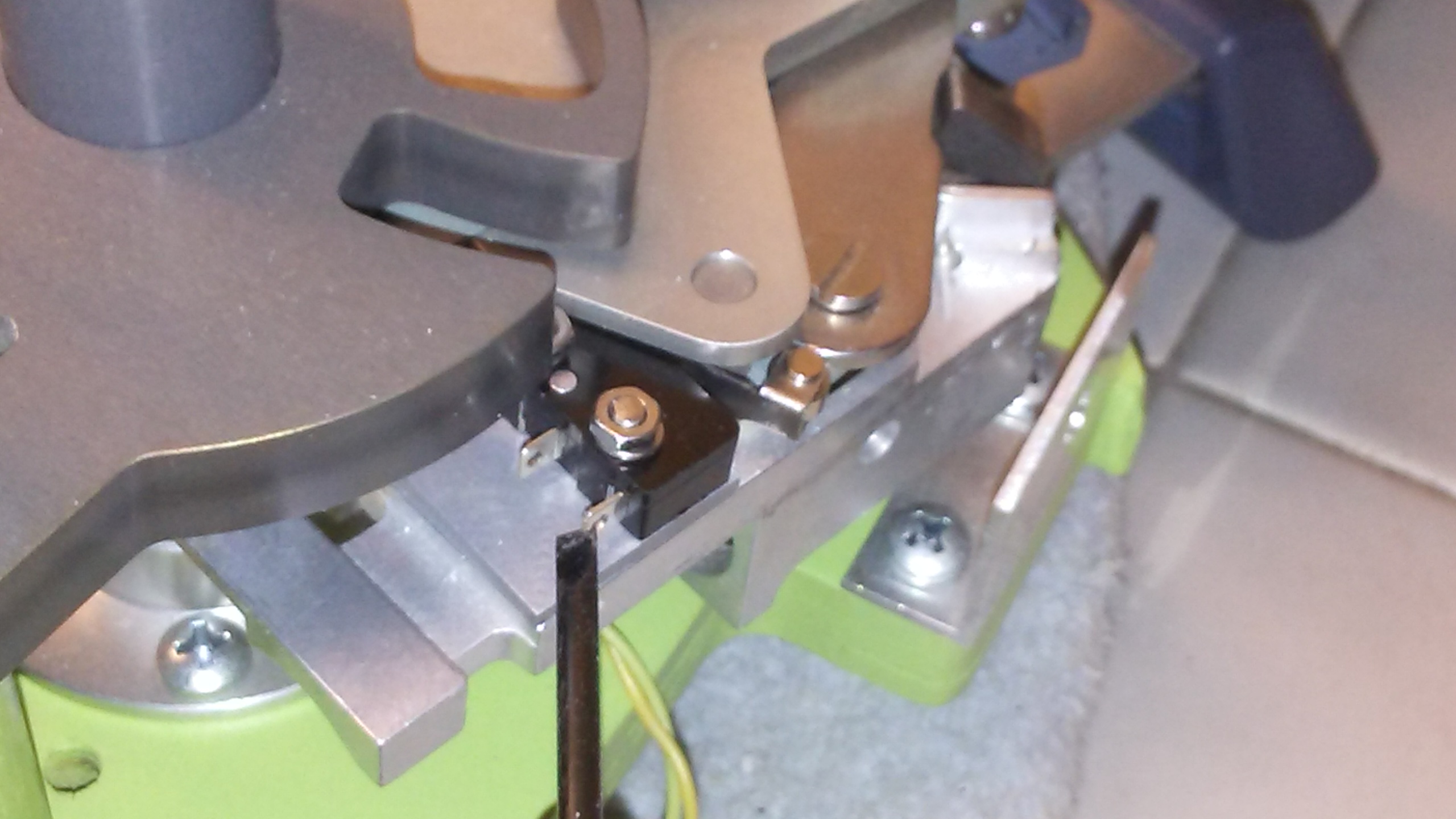
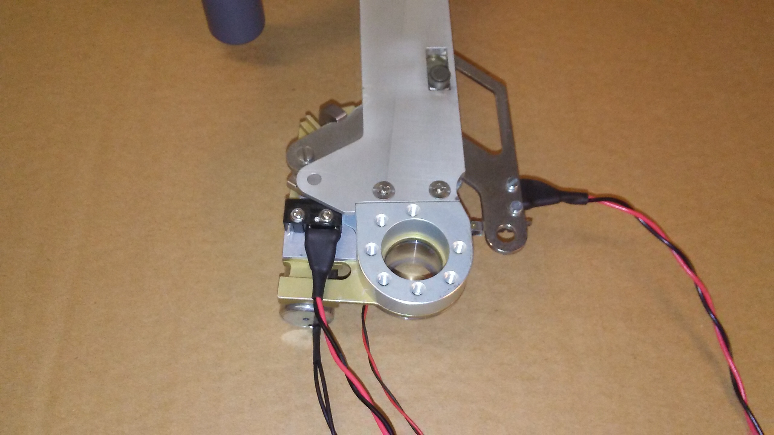
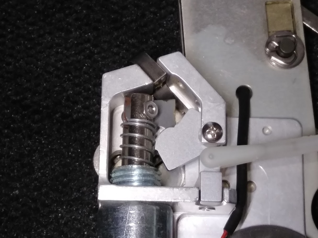
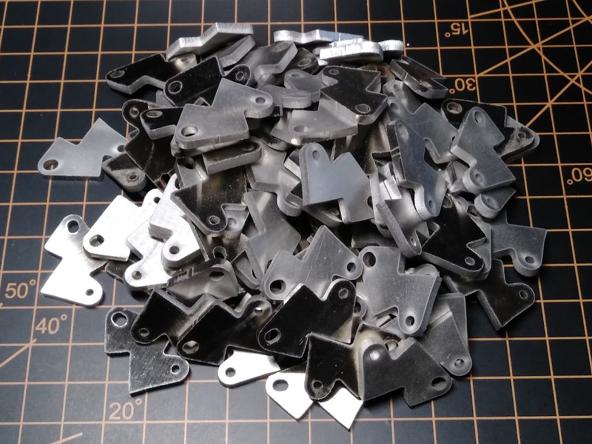
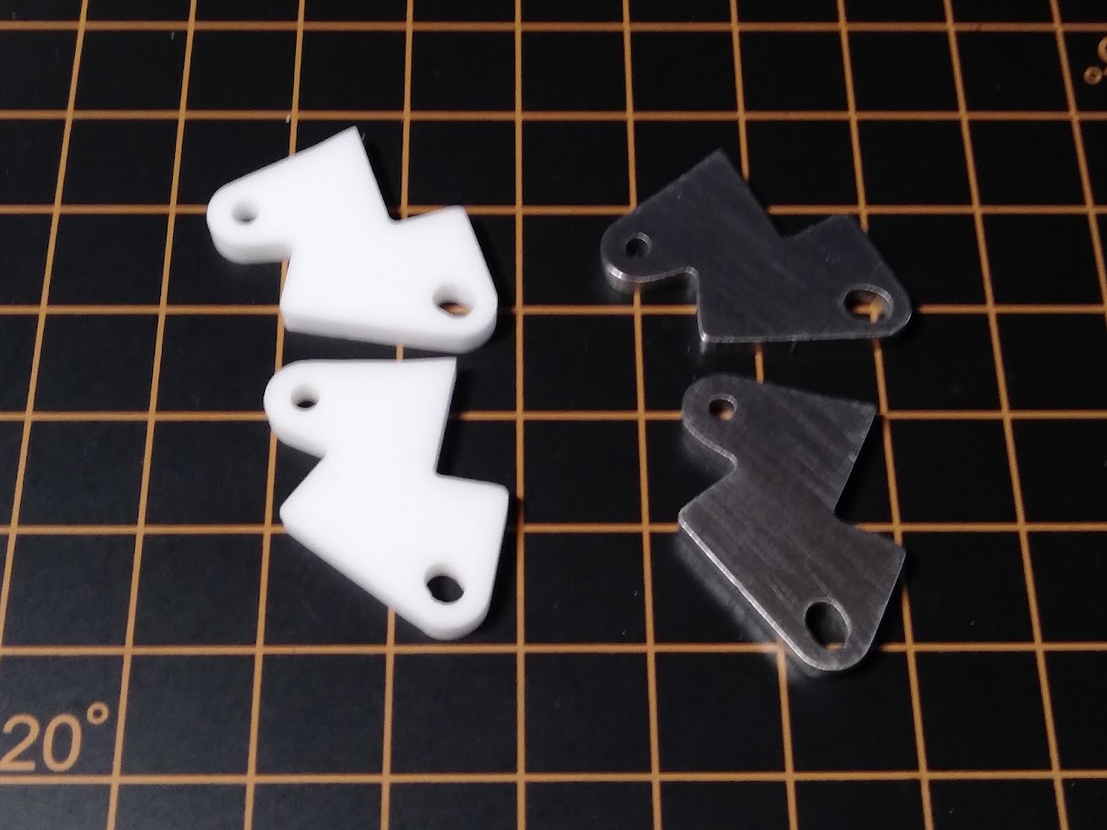
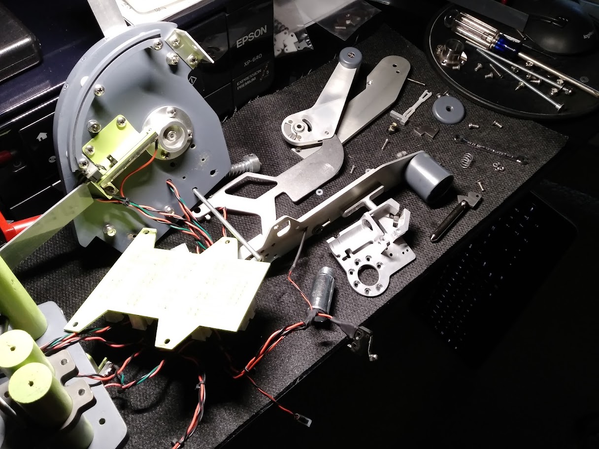
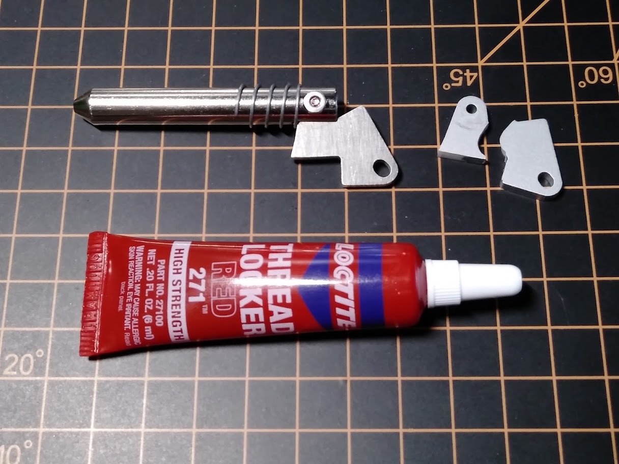
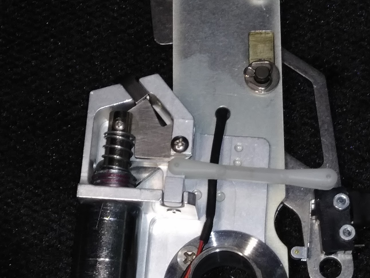
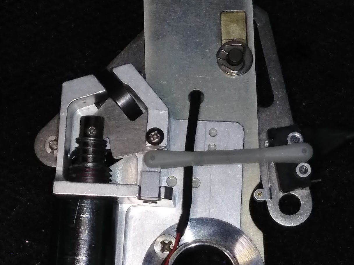
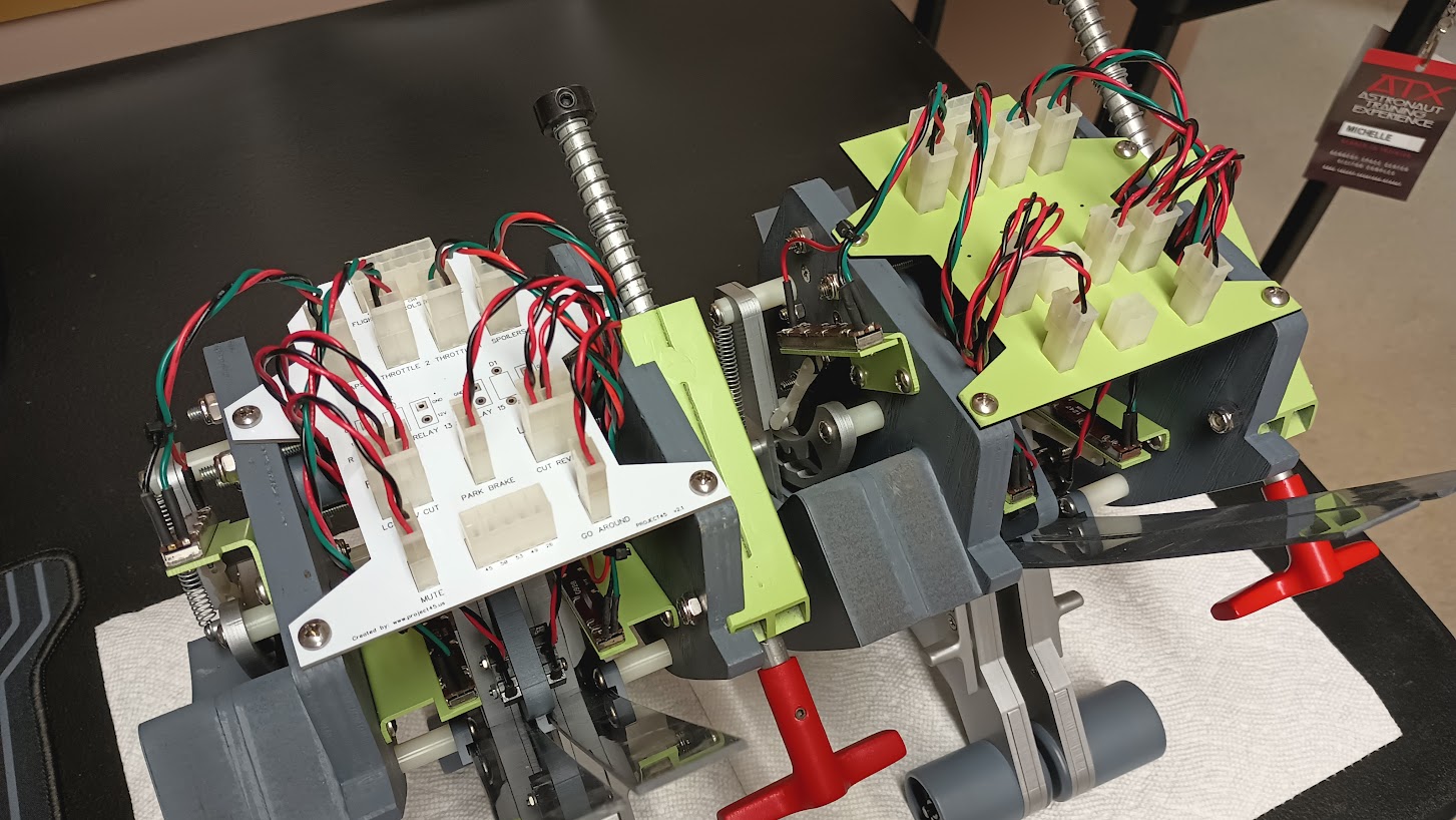
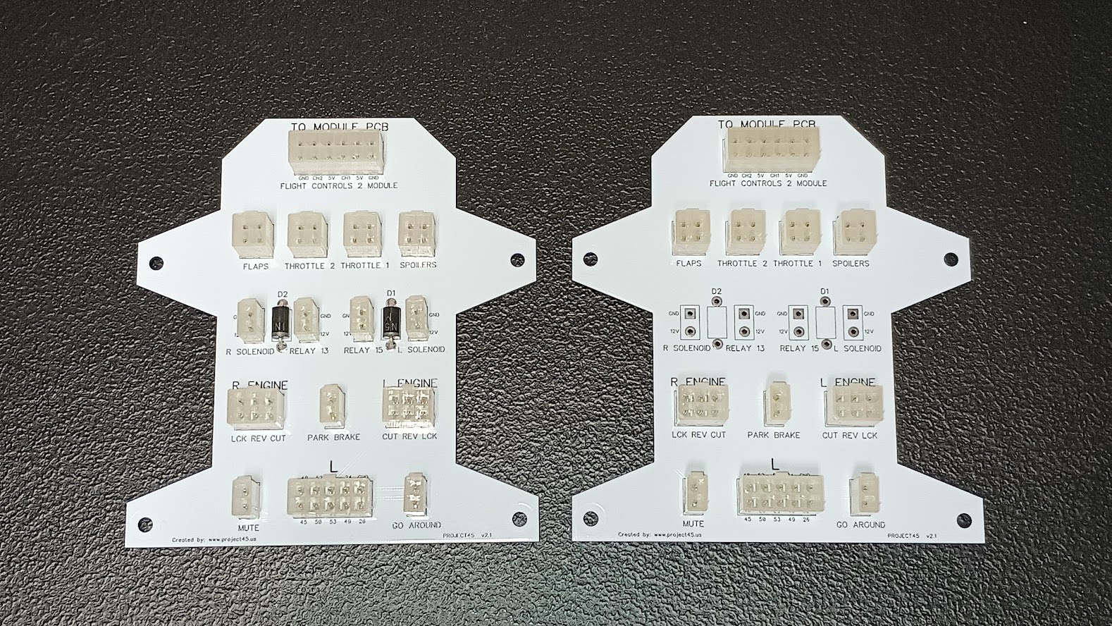
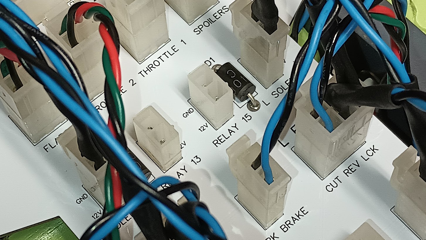
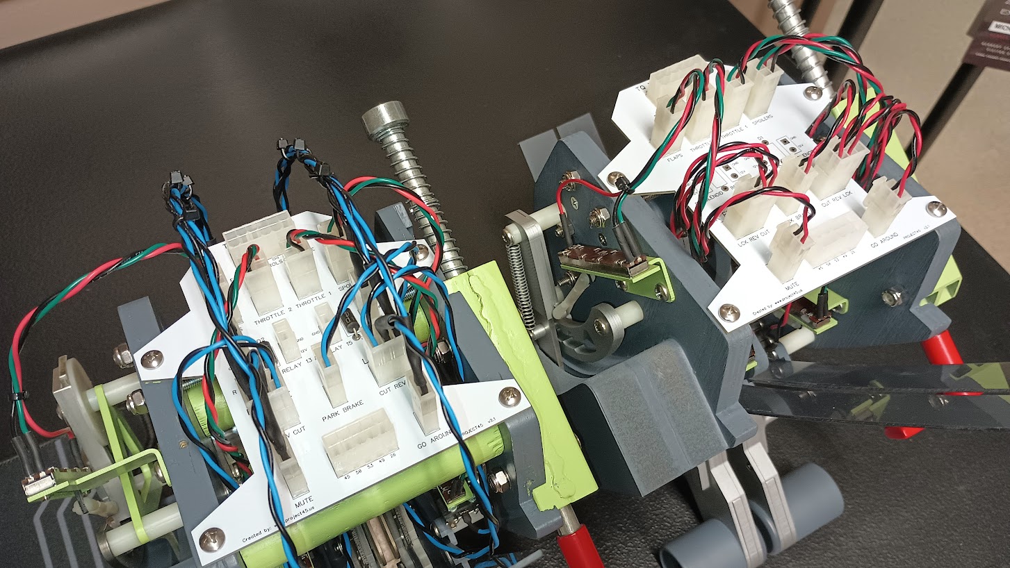
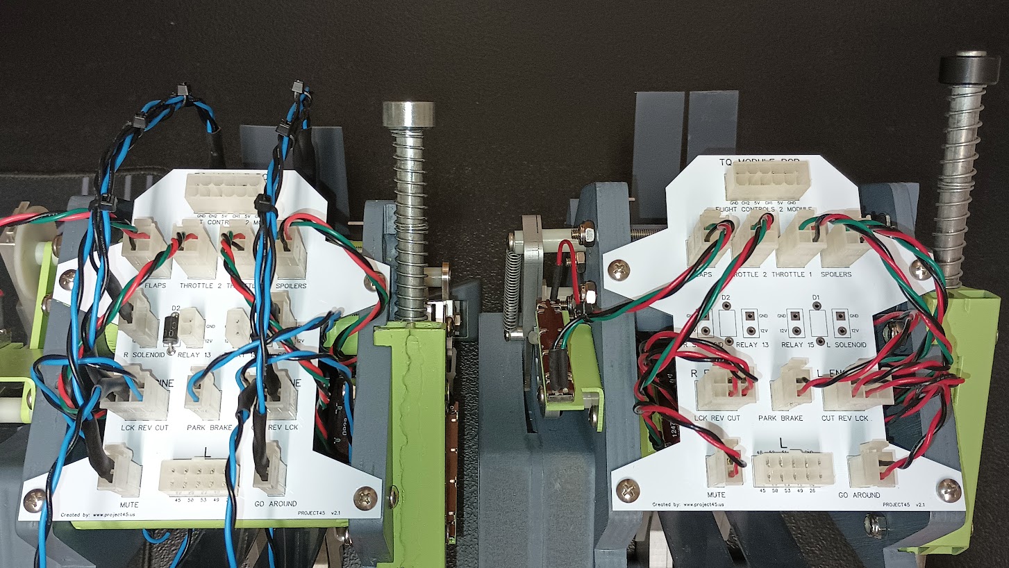
Hey Mark and Mark, It looks like you are on the right track! There is life in the reverser lockout solenoid system thanks to you two! Watching the video and listening to the second video, it sounds like the solenoids are activating when weight on wheels is detected. This is not correct. If the solenoids are energized all the time, it will cause damage to them and or the plastic parts they are attached to. If this is in fact the case, to correct this, I have included ANOTHER set of micro switches that activate when you pull the reversers back to the first notch. The travel of the reversers to activate these switches is less than a half inch. These switches need to be included in on the conditions for the solenoids to be activated, otherwise, they will stay energized way too long while on the ground potentially causing damage. There is more information on the first sequence of micro switches in post #12 and #19 of this thread. Here they are in these two photos below: In the photo below, it is the switch on the left. When you pull back on the reverser levers, the metal internal levers hit these switches. If everything works properly, in a micro second, FSUIPC will detect that all conditions are met and the solenoids will activate allowing you to continue to pull the reverser levers all the way back until they activate the second micro switch in the sequence. You got that one right and squared away in the video so don't mess with those settings. The second set of micro switches actually activates the clam doors on the back end of the engines like you see in the video. Heck of a puzzle but you are on the right track! Once everything is set up properly, the one thing I was concerned about is if you pull too hard and fast on the reverser levers, will it put too much pressure on the mechanical moving parts and prevent the solenoid from activating? That is something to keep an eye out for. I think it will come down to how fast FSUIPC activates the solenoids. The good news is, if it is as fast as it detects weight on wheel like in your video, it will be instantaneous and not an issue! Please keep us posted on the progress and keep up the ground breaking work! Exciting stuff! UPDATE! Mark, Shane and I were talking about the issue at hand and I think I made it sound more confusing than it needed to be. The solution to the problem is really simple. Just use that first micro switch that I refer to in this post to break one of the lines, either the ground line or the power line going to the solenoid. DONE. You already have everything set up in FSUIPC correct! Once you have the first micro switch wired directly into the solenoid, it will keep the solenoid from energizing unless it is selected by the switch. This way the solenoid is only energized when you actually need it as designed. In flight, if you try to select the solenoids via the reversers and the first micro switch, nothing will happen as you demonstrated in the video. So with all this said, you are closer than you think to having it perfectly right. And the bonus to this extra thought process: My concern if FSUIPC will cycle fast enough is not an issue. The way you have it programmed now selects weight on wheels at the first touch of the wheels on the ground. So the computing part of the equation is already handled. A second or two later when you pull back on the reverse levers and close that first micro switch, power will be applied to the solenoids instantaneously! So this should not be an issue but we need to prove it first. Hey Mark and Mark, It looks like you are on the right track! There is life in the reverser lockout solenoid system thanks to you two! Watching the video and listening to the second video, it sounds like the solenoids are activating when weight on wheels is detected. This is not correct. If the solenoids are energized all the time, it will cause damage to them and or the plastic parts they are attached to. If this is in fact the case, to correct this, I have included ANOTHER set of micro switches that activate when you pull the reversers back to the first notch. The travel of the reversers to activate these switches is less than a half inch. These switches need to be included in on the conditions for the solenoids to be activated, otherwise, they will stay energized way too long while on the ground potentially causing damage. There is more information on the first sequence of micro switches in post #12 and #19 of this thread. Here they are in these two photos below: In the photo below, it is the switch on the left. When you pull back on the reverser levers, the metal internal levers hit these switches. If everything works properly, in a micro second, FSUIPC will detect that all conditions are met and the solenoids will activate allowing you to continue to pull the reverser levers all the way back until they activate the second micro switch in the sequence. You got that one right and squared away in the video so don't mess with those settings. The second set of micro switches actually activates the clam doors on the back end of the engines like you see in the video. Heck of a puzzle but you are on the right track! Once everything is set up properly, the one thing I was concerned about is if you pull too hard and fast on the reverser levers, will it put too much pressure on the mechanical moving parts and prevent the solenoid from activating? That is something to keep an eye out for. I think it will come down to how fast FSUIPC activates the solenoids. The good news is, if it is as fast as it detects weight on wheel like in your video, it will be instantaneous and not an issue! Please keep us posted on the progress and keep up the ground breaking work! Exciting stuff! UPDATE! Mark, Shane and I were talking about the issue at hand and I think I made it sound more confusing than it needed to be. The solution to the problem is really simple. Just use that first micro switch that I refer to in this post to break one of the lines, either the ground line or the power line going to the solenoid. DONE. You already have everything set up in FSUIPC correct! Once you have the first micro switch wired directly into the solenoid, it will keep the solenoid from energizing unless it is selected by the switch. This way the solenoid is only energized when you actually need it as designed. In flight, if you try to select the solenoids via the reversers and the first micro switch, nothing will happen as you demonstrated in the video. So with all this said, you are closer than you think to having it perfectly right. And the bonus to this extra thought process: My concern if FSUIPC will cycle fast enough is not an issue. The way you have it programmed now selects weight on wheels at the first touch of the wheels on the ground. So the computing part of the equation is already handled. A second or two later when you pull back on the reverse levers and close that first micro switch, power will be applied to the solenoids instantaneously! So this should not be an issue but we need to prove it first. Hi Members, Sorry for the delay but here is the final update for the Learjet thrusters. Coop and I ( The Mark's Brothers !) tried lots of different combinations of wiring but we finally settled on what Shane and Ron alluded to anyway. For those of you who haven't followed or understand this part of the sim, here is the executive summary. When trying to connect the Throttle Quadrant hardware to the flight simulator ( in our case P3D v4.5 ) you will need to connect some of the wiring to the Interface IT board. https://flightdeck-solutions.myshopify.com/collections/interfaceit-sys-boards The rest of the wiring will be to an IO board. Examples are a Leo Bodnar board. https://www.leobodnar.com/shop/index.php?main_page=index&cPath=94 or in our case and works fine, a Pokeys board. I chose the Pokeys as I had a few spare. https://www.poscope.com/product/pokeys57u/ I think the best advice is the Leo Bodnar board as it is cheaper and is a less hassles way to go. This one or the next one up. So once you have the hardware chosen you need to work out which combination of wiring is the most proficient. So the best method is to wire the Reverser Lockout switch so that it allows a circuit to energize the two Solenoids. This wiring will be attached as Left and Right Thrusters to the Interface IT Relay Board. As you pull the Reverser Levers all the way up, as now allowed by the Solenoids, the Reverser Switches kick in and you get a reverse thrust. In order for this to occur you need to assign offsets to whatever wires are attached to whichever board. For the Relay Board we just chose the option 'Plane on Ground'. This ensures that a circuit will be made 'IF' the Reverser Lockout switch is activated and the plane is on the ground. This activates the solenoid which will then allow you to keep pulling the levers back fully. Once fully engaged the Reverser Switches are activated to give Reverse Thrust. These wires from the Reverser switches were attached to in our case the FDS Sys 2 board. After MUCH testing here is the Offsets that we could satisfactorily get to work. In Interface IT, once you 've located the correct Reverser switch, add two FSUIPC On/Down actions; Rev 1 Offset: 088C Type: Word Operation: Set Value Value: -8596 (Note value negative and adjust as required, that gave us 85% reverse thrust if left to spool up) Rev 2 Offset: 0924 Type: Word Operation: Set Value Value: -8596 Also add two FSUIPC Off/Up actions Rev 1 Offset: 088C Type: Word Operation: Set Value Value: 0 Rev 2 Offset: 0924 Type: Word Operation: Set Value Value: 0 So here is the video. Sorry about orientation but flying and filming is tricky. Note the click of the solenoid. https://youtu.be/E9Vwl7QgEsU Cheers Mark Speechley and Mark Cooper Hi Members, Sorry for the delay but here is the final update for the Learjet thrusters. Coop and I ( The Mark's Brothers !) tried lots of different combinations of wiring but we finally settled on what Shane and Ron alluded to anyway. For those of you who haven't followed or understand this part of the sim, here is the executive summary. When trying to connect the Throttle Quadrant hardware to the flight simulator ( in our case P3D v4.5 ) you will need to connect some of the wiring to the Interface IT board. https://flightdeck-solutions.myshopify.com/collections/interfaceit-sys-boards The rest of the wiring will be to an IO board. Examples are a Leo Bodnar board. https://www.leobodnar.com/shop/index.php?main_page=index&cPath=94 or in our case and works fine, a Pokeys board. I chose the Pokeys as I had a few spare. https://www.poscope.com/product/pokeys57u/ I think the best advice is the Leo Bodnar board as it is cheaper and is a less hassles way to go. This one or the next one up. So once you have the hardware chosen you need to work out which combination of wiring is the most proficient. So the best method is to wire the Reverser Lockout switch so that it allows a circuit to energize the two Solenoids. This wiring will be attached as Left and Right Thrusters to the Interface IT Relay Board. As you pull the Reverser Levers all the way up, as now allowed by the Solenoids, the Reverser Switches kick in and you get a reverse thrust. In order for this to occur you need to assign offsets to whatever wires are attached to whichever board. For the Relay Board we just chose the option 'Plane on Ground'. This ensures that a circuit will be made 'IF' the Reverser Lockout switch is activated and the plane is on the ground. This activates the solenoid which will then allow you to keep pulling the levers back fully. Once fully engaged the Reverser Switches are activated to give Reverse Thrust. These wires from the Reverser switches were attached to in our case the FDS Sys 2 board. After MUCH testing here is the Offsets that we could satisfactorily get to work. In Interface IT, once you 've located the correct Reverser switch, add two FSUIPC On/Down actions; Rev 1 Offset: 088C Type: Word Operation: Set Value Value: -8596 (Note value negative and adjust as required, that gave us 85% reverse thrust if left to spool up) Rev 2 Offset: 0924 Type: Word Operation: Set Value Value: -8596 Also add two FSUIPC Off/Up actions Rev 1 Offset: 088C Type: Word Operation: Set Value Value: 0 Rev 2 Offset: 0924 Type: Word Operation: Set Value Value: 0 So here is the video. Sorry about orientation but flying and filming is tricky. Note the click of the solenoid. Cheers Mark Speechley and Mark Cooper Outstanding review and final instructions Mark! I am really happy to see that we have one set of reversers working. More will soon follow! Thanks Mark and Mark for spearheading this effort! Outstanding review and final instructions Mark! I am really happy to see that we have one set of reversers working. More will soon follow! Thanks Mark and Mark for spearheading this effort! UPDATE! (This only effects the authentic TQ Modules) We had to make a material change in reference to the Reverser "Missing Links" in the authentic TQ modules. The shape and function of the Missing Links are fine but they do not hold up to moderate stress let alone extreme forces. In other words, if you pull the reverser levels too hard when they are not to be deployed, the missing links will fail. This happen to my TQ set and it was not even operational yet. I believe this has also happened to Mark's TQ module. Here is a photo of the link snapped in half: The solution to the problem is switching to stainless steel material. The problem with that is my CNC can't even handle thin gauge aluminum let alone steel, so a trip to the Waterjet shop was in order. We will never need 100 pieces among all of us in our group but I might as well buy them to cover the minimum cost to fire up the waterjet. I am sure I have mentioned this in the past but as of this date, we can only speculate what this part looks like because we have no drawings of it. This design is my rendition and interpretation of what the part looks like. It is also how it gets it's nickname, the "Missing Link"! Here is a comparison of the cast plastic version (left) compared to the stainless steel version (right): Unfortunately, there is no easy way to replace the links. It requires a complete tear down of the TQ module, including the throttle levers themselves! And there is no easy way to try to explain how to tear down and build back up the TQ modules although not difficult, it is time consuming. You might want to take several photos along the way. The photo below shows how far I had to go to get to the links: Below is the new replacement Missing Link installed on the solenoid plunger. A couple quick points, the waterjet took the shape to 98% of what we need. I took the links another 1% insuring the holes were opened properly and removing the tooling burs. The last 1% will be taken care of by the installer which requires a little sanding of the contact edge. Another thing you will surely want to do is to use Loctite Thread Locker to lock the screws and the nuts together. These areas are so tight that a lock washer can not be used and the last thing you want is any of these pieces working themselves loose. Additionally, I found that I had to snip some length off of the spring on the solenoid plunger a little at a time until I found the correct length. Actually the length is not the issue, it's the strength of the spring that has to be adjusted. In my case, I had to reduce the strength so that the link would release the lock. This photo shows the missing link blocking the reverser lock. In this configuration, the reversers can not be selected. This photo shows the solenoid energized and pulling the missing link down. This allows the reverser locks to fall making it possible to activate the reversers! After some tweaking, filling and snipping at the spring, I was able to get the mechanisms set just right! Of course everything you see here is X2 for the other lever. Once everything is tweaked and back together there is no way that the missing links will ever fail in the same manor as the cast plastic versions did as long as extreme forces are not applied. My guess is something else will fail before the stainless steel missing links do! UPDATE! (This only effects the authentic TQ Modules) We had to make a material change in reference to the Reverser "Missing Links" in the authentic TQ modules. The shape and function of the Missing Links are fine but they do not hold up to moderate stress let alone extreme forces. In other words, if you pull the reverser levels too hard when they are not to be deployed, the missing links will fail. This happen to my TQ set and it was not even operational yet. I believe this has also happened to Mark's TQ module. Here is a photo of the link snapped in half: The solution to the problem is switching to stainless steel material. The problem with that is my CNC can't even handle thin gauge aluminum let alone steel, so a trip to the Waterjet shop was in order. We will never need 100 pieces among all of us in our group but I might as well buy them to cover the minimum cost to fire up the waterjet. I am sure I have mentioned this in the past but as of this date, we can only speculate what this part looks like because we have no drawings of it. This design is my rendition and interpretation of what the part looks like. It is also how it gets it's nickname, the "Missing Link"! Here is a comparison of the cast plastic version (left) compared to the stainless steel version (right): Unfortunately, there is no easy way to replace the links. It requires a complete tear down of the TQ module, including the throttle levers themselves! And there is no easy way to try to explain how to tear down and build back up the TQ modules although not difficult, it is time consuming. You might want to take several photos along the way. The photo below shows how far I had to go to get to the links: Below is the new replacement Missing Link installed on the solenoid plunger. A couple quick points, the waterjet took the shape to 98% of what we need. I took the links another 1% insuring the holes were opened properly and removing the tooling burs. The last 1% will be taken care of by the installer which requires a little sanding of the contact edge. Another thing you will surely want to do is to use Loctite Thread Locker to lock the screws and the nuts together. These areas are so tight that a lock washer can not be used and the last thing you want is any of these pieces working themselves loose. Additionally, I found that I had to snip some length off of the spring on the solenoid plunger a little at a time until I found the correct length. Actually the length is not the issue, it's the strength of the spring that has to be adjusted. In my case, I had to reduce the strength so that the link would release the lock. This photo shows the missing link blocking the reverser lock. In this configuration, the reversers can not be selected. This photo shows the solenoid energized and pulling the missing link down. This allows the reverser locks to fall making it possible to activate the reversers! After some tweaking, filling and snipping at the spring, I was able to get the mechanisms set just right! Of course everything you see here is X2 for the other lever. Once everything is tweaked and back together there is no way that the missing links will ever fail in the same manor as the cast plastic versions did as long as extreme forces are not applied. My guess is something else will fail before the stainless steel missing links do! Hey guys, I have been busy rewiring all my panels and have finally got down to the "nitty gritty" areas. One of those areas is the TQ module. I wanted to correct my wiring color to match exactly what we have in the Jet45 AAS Systems Module document. If for nothing else, to set a good example! While I had the TQ module taken down, I also went ahead and updated the TQ module wire management clad with pcb. Here are a couple replica TQ modules, one with the original wire management in clad (color green on the right) and the new wire management in pcb (color white on the left). I designed this new wire management pcb for the TQ module(s) to work with both the authentic TQ module and the replica TQ module. The only difference is with the replicas, you don't use the reverser solenoids or the solenoid lock pins. The one on the left is ready for an authentic TQ module while the one on the right is ready for the replica TQ module. (They are both the same pcb design) I also grouped the lower pins leaving the pcb into one plug called "L". This plug now agrees with the Pedestal Panels Module in the Jet45 AAS Systems Modules document. Another updated feature is now all plugs and pins are properly marked. This way during trouble shooting efforts, it will be much easier to identify what is what. Note that the four plugs with nothing in them yet will run back to the interface modules. And here are two examples of the TQ modules with updated pcb. The authentic version on the left and the replica version on the right. If you have either a authentic TQ or a replica that follows the Project45 design and wound like the pcb update, just send me a message. No charge for the updated pcb! Hey guys, I have been busy rewiring all my panels and have finally got down to the "nitty gritty" areas. One of those areas is the TQ module. I wanted to correct my wiring color to match exactly what we have in the Jet45 AAS Systems Module document. If for nothing else, to set a good example! While I had the TQ module taken down, I also went ahead and updated the TQ module wire management clad with pcb. Here are a couple replica TQ modules, one with the original wire management in clad (color green on the right) and the new wire management in pcb (color white on the left). I designed this new wire management pcb for the TQ module(s) to work with both the authentic TQ module and the replica TQ module. The only difference is with the replicas, you don't use the reverser solenoids or the solenoid lock pins. The one on the left is ready for an authentic TQ module while the one on the right is ready for the replica TQ module. (They are both the same pcb design) I also grouped the lower pins leaving the pcb into one plug called "L". This plug now agrees with the Pedestal Panels Module in the Jet45 AAS Systems Modules document. Another updated feature is now all plugs and pins are properly marked. This way during trouble shooting efforts, it will be much easier to identify what is what. Note that the four plugs with nothing in them yet will run back to the interface modules. And here are two examples of the TQ modules with updated pcb. The authentic version on the left and the replica version on the right. If you have either a authentic TQ or a replica that follows the Project45 design and wound like the pcb update, just send me a message. No charge for the updated pcb! Maybe this have been discussed before, but has anyone see these Learjet throttles on the market? https://throttletek.com/lear-45-g-throttle/ They look rugged and are plug and play. Just don't know if they are 'scale' enough for us to use so Ron doesn't have to spend 100 hours making sets if he's not profiting off them. Nice to have another source that is not Chinese made. Maybe this have been discussed before, but has anyone see these Learjet throttles on the market? They look rugged and are plug and play. Just don't know if they are 'scale' enough for us to use so Ron doesn't have to spend 100 hours making sets if he's not profiting off them. Nice to have another source that is not Chinese made. Hey Jason, Way back in October 2016, Jeff Peters discovered this throttle unit and was asking about it. Maciej actually pulled the trigger and purchased one and was not happy with it to say the least. He ended up sending it to me to see if I could do anything with it. At first, I thought I was going to be able to work with it but the deeper I went the more parts had to be replaced with my parts or new parts until there was nothing left but a box of garbage to mail back to Maciej. I ended up giving Maciej one of my replica TQ modules, (like you have) at no charge for being the brave one and purchasing one of these Throttletek units. My TQ module is not perfect and is even missing a key feature, the thrust reverser lockout, but it's functional and looks squared away! What Throttletek sent Maciej, they should be embarrassed, especially for the amount of money they charged him. I don't like to talk bad about other folks work, but in this case, I have to because I don't want to see another serious Lear45 builder get screwed out of nearly $2,000. For the full story and breakdown, go back to the beginning of this thread and look for this post below. It's an interesting read and if nothing else, the Throttletek TQ module helped to push me to develop our own version of it. (Posted by Ron Rollo on 01-16-17) Maciej took the plunge and purchased a Throttletek Lear45 TQ. To say the least, Maciej was not impressed with the quality and the functionality of the unit so I offered to take it on to see what I could do with it...... Hey Jason, Way back in October 2016, Jeff Peters discovered this throttle unit and was asking about it. Maciej actually pulled the trigger and purchased one and was not happy with it to say the least. He ended up sending it to me to see if I could do anything with it. At first, I thought I was going to be able to work with it but the deeper I went the more parts had to be replaced with my parts or new parts until there was nothing left but a box of garbage to mail back to Maciej. I ended up giving Maciej one of my replica TQ modules, (like you have) at no charge for being the brave one and purchasing one of these Throttletek units. My TQ module is not perfect and is even missing a key feature, the thrust reverser lockout, but it's functional and looks squared away! What Throttletek sent Maciej, they should be embarrassed, especially for the amount of money they charged him. I don't like to talk bad about other folks work, but in this case, I have to because I don't want to see another serious Lear45 builder get screwed out of nearly $2,000. For the full story and breakdown, go back to the beginning of this thread and look for this post below. It's an interesting read and if nothing else, the Throttletek TQ module helped to push me to develop our own version of it. (Posted by Ron Rollo on 01-16-17) Maciej took the plunge and purchased a Throttletek Lear45 TQ. To say the least, Maciej was not impressed with the quality and the functionality of the unit so I offered to take it on to see what I could do with it...... Thanks Ron. I did some internet digging found a few negative reviews of the product and customer service. Couple that with their T&Cs saying you cannot post any pictures of the internals of the quadrants and threaten their customers with legal action is a big red flag. Those of us that have them know that the 'Rollo' products and customer service are second to none! As long as you don't decide to retire, the builders have a solid one stop shop for their builds (no pressure) 🙂 Thanks Ron. I did some internet digging found a few negative reviews of the product and customer service. Couple that with their T&Cs saying you cannot post any pictures of the internals of the quadrants and threaten their customers with legal action is a big red flag. Those of us that have them know that the 'Rollo' products and customer service are second to none! As long as you don't decide to retire, the builders have a solid one stop shop for their builds (no pressure) 🙂 Thanks Jason! They don't want anyone posting photos of what's inside because it's terrible craftsmanship, not proprietary parts or knowledge. You talk about legal action? If I had spent $2,000 and received what Maciej got, we would have a big problem. I think we are at the point in the evolution of sim building that if we can't do it well, don't do it at all! Some of my early work was not the best quality but it worked! Reference this company we are talking about, it's been ten years. Hopefully their quality and craftsmanship have got better with the things they are putting out there for sale to the sim community. As you said earlier, it would be great if there were a couple guys out there making quality parts for the Lera45 even if they were not 100% compatible with our scale and path forward. Just having other guys out there building the Lera45 would be a win for us. Thanks Jason! They don't want anyone posting photos of what's inside because it's terrible craftsmanship, not proprietary parts or knowledge. You talk about legal action? If I had spent $2,000 and received what Maciej got, we would have a big problem. I think we are at the point in the evolution of sim building that if we can't do it well, don't do it at all! Some of my early work was not the best quality but it worked! Reference this company we are talking about, it's been ten years. Hopefully their quality and craftsmanship have got better with the things they are putting out there for sale to the sim community. As you said earlier, it would be great if there were a couple guys out there making quality parts for the Lera45 even if they were not 100% compatible with our scale and path forward. Just having other guys out there building the Lera45 would be a win for us. I remember that! This was a big pile of amateur glued/taped together pile of nonsense. It resembled quality of mechanical Chinese Xmas decorations, absolute garbage. There was no other option at that time to grab original piece, so I decided to become a lab mouse. The only good thing was for us to know to stay away from it. I remember that! This was a big pile of amateur glued/taped together pile of nonsense. It resembled quality of mechanical Chinese Xmas decorations, absolute garbage. There was no other option at that time to grab original piece, so I decided to become a lab mouse. The only good thing was for us to know to stay away from it.Throttle Quadrant by Project45
![]()
![]()
![]()
![]()
![]()

![]()
![]()
![]()
![]()
![]()
Forum NavigationThrottle Quadrant by Project45
![]() #31 · May 4, 2019, 4:21 pm
#31 · May 4, 2019, 4:21 pm![]() #32 · June 22, 2019, 7:07 am
#32 · June 22, 2019, 7:07 am![]() #33 · June 23, 2019, 8:08 pm
#33 · June 23, 2019, 8:08 pm![]() #34 · February 20, 2022, 9:05 pm
#34 · February 20, 2022, 9:05 pm![]() #35 · March 20, 2024, 1:20 pm
#35 · March 20, 2024, 1:20 pm![]() #36 · January 13, 2026, 6:44 pmRon Rollo has reacted to this post.Ron RolloJason Hite
FlightDeckSoft
#36 · January 13, 2026, 6:44 pmRon Rollo has reacted to this post.Ron RolloJason Hite
FlightDeckSoft![]() #37 · January 14, 2026, 9:58 am
#37 · January 14, 2026, 9:58 am![]() #38 · January 14, 2026, 12:19 pmRon Rollo and Mark Speechley have reacted to this post.Ron RolloMark SpeechleyJason Hite
FlightDeckSoft
#38 · January 14, 2026, 12:19 pmRon Rollo and Mark Speechley have reacted to this post.Ron RolloMark SpeechleyJason Hite
FlightDeckSoft![]() #39 · January 14, 2026, 5:11 pmMark Speechley has reacted to this post.Mark Speechley
#39 · January 14, 2026, 5:11 pmMark Speechley has reacted to this post.Mark Speechley![]() #40 · February 1, 2026, 5:57 pm
#40 · February 1, 2026, 5:57 pm
2017-10-10