


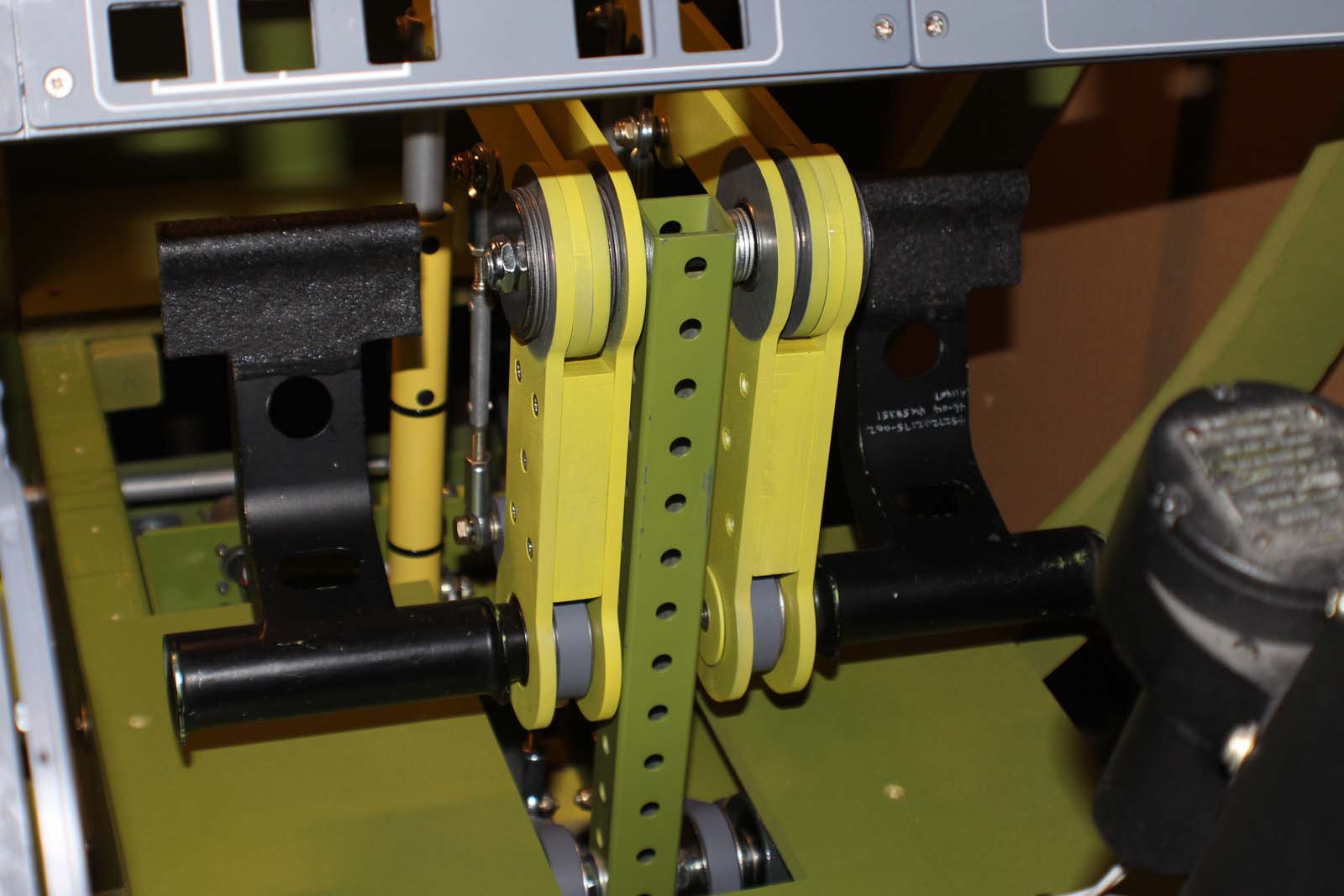
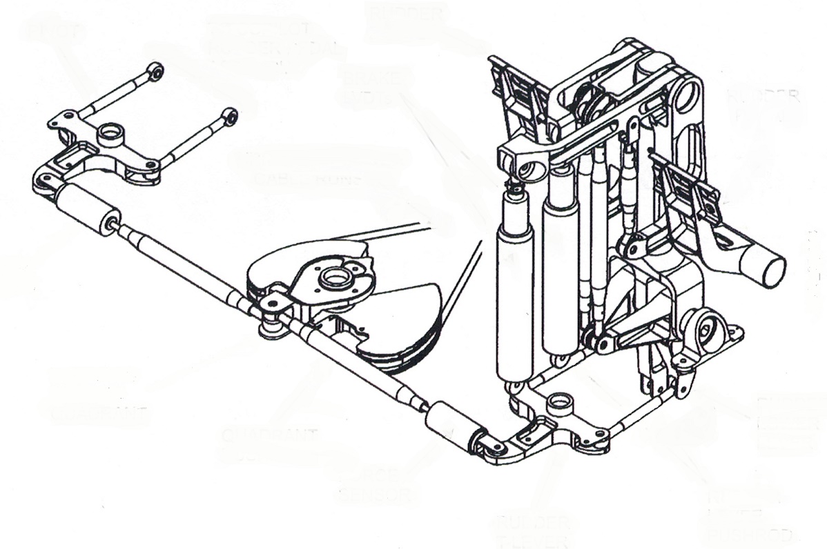
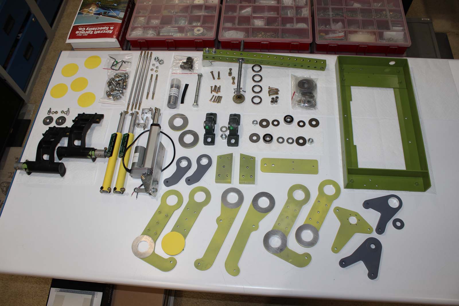
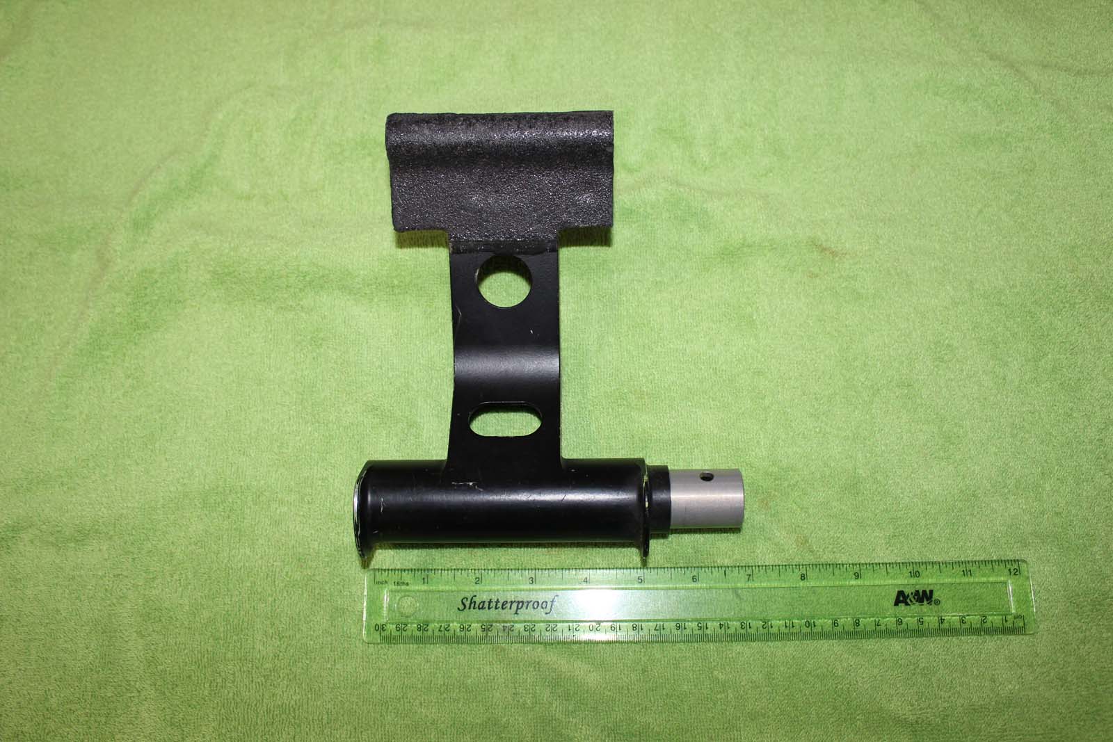
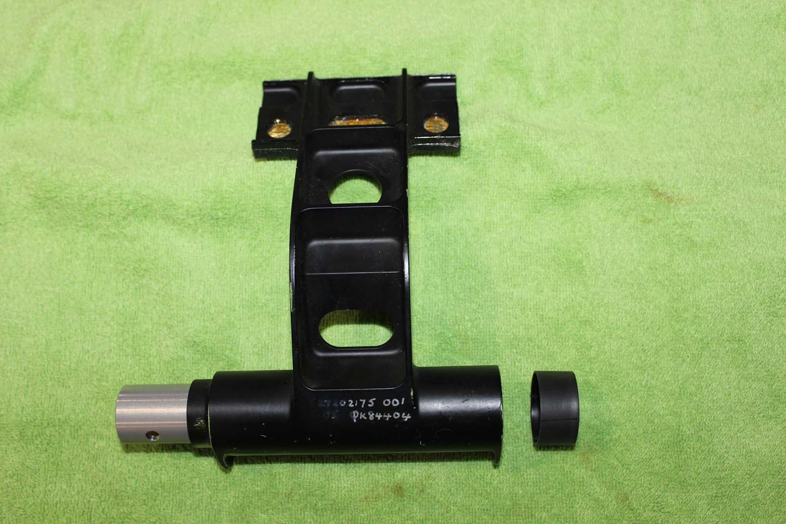
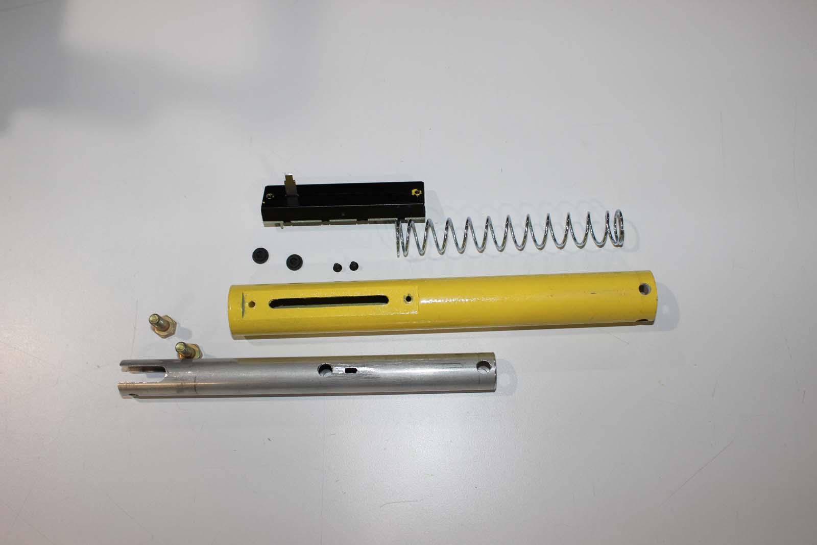
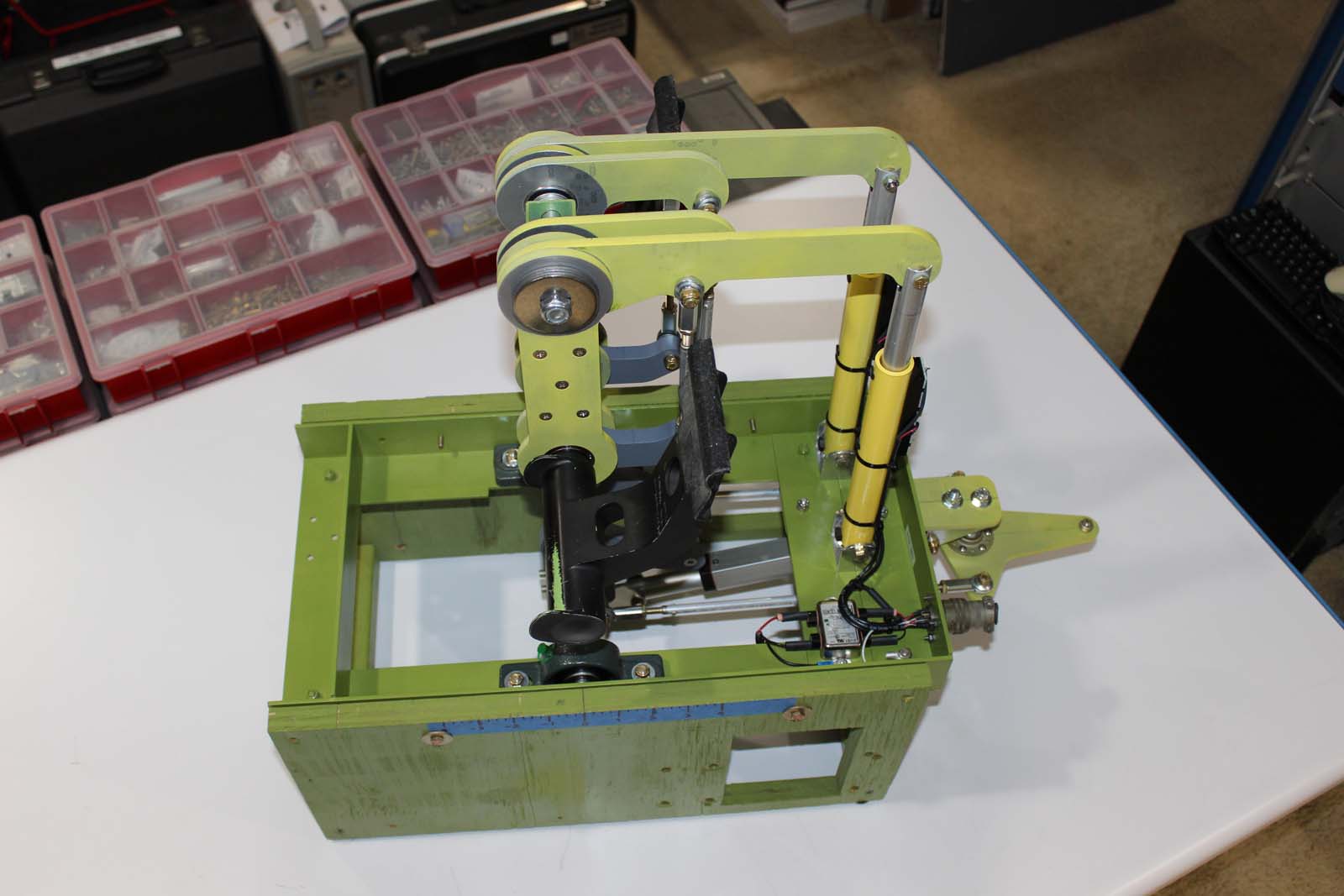
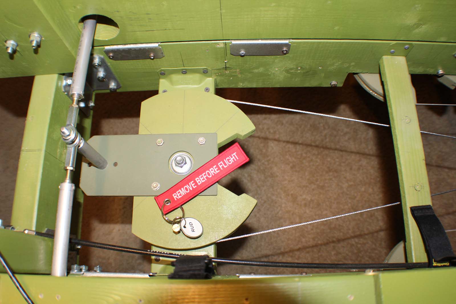
Lear 45-1001 Build History ATA 27-20 Rudder Control System Rev 22 Dec 2022 The L45-1001 introduction contains useful background information on this build. If somehow you have arrived at this place and have not read the L45-1001 introduction you will find it HERE: Welcome Aboard https://hangar45.net/wp-content/uploads/2022/12/Welcome-Aboard.mp4 Rudder: The rudder control system in the Lear 45 consists of pedal assemblies, the forward rudder quadrant, control cables located under the floor that run back to the tail cone, the rudder surface itself, and an assortment of pulleys, servos, and components. It is a mechanically operated system driven by pilot inputs via foot pedals in the cockpit. A servo located in the control cable circuit provides rudder surface movements associated with the autopilot, yaw damper, and rudder boost system. This discussion covers the rudder pedal assemblies, the forward rudder quadrant, and the control cables. Functions associated with the autopilot, yaw damper, and rudder boost system are discussed under “Auto Flight”, ATA 22. Many Moving Parts: It is difficult to describe the complexity of the many moving parts by use of the printed word. I’ll not even attempt it. Please see the video below to gain an appreciation of the many parts of the rudder control system in motion simultaneously. This is what happens when a pilot presses on a rudder pedal. https://hangar45.net/wp-content/uploads/2022/12/Many-Moving-Parts.mp4 YOU can build rudder pedal assemblies: I am not a mechanical engineer and do not have access to a machine shop filled with tooling. I cannot take credit for the design of this replica rudder control system. My contribution to the pedal effort is to devise a method of fabrication that can be employed by other simulator builders. I believe that most builders can follow this example and successfully build their own rudder controls. But the effort is not like assembling an Ikea bookcase. You must have good basic hand tools, a small drill press, the skills to use them, and the ability to FOLLOW DIRECTIONS on how to make and assemble the parts. Rudder pedals and the control system are complicated, but YOU CAN DO THIS with average skills and tooling. I say that because that’s all I have and that is what I used to successfully build this system. Do these pedals work with a Ron Shell kit? Ron and I have had considerable discussion about ways he might adapt this design to work with the Ron Shell. The basic problem is that the Ron Shell is 12 inches shorter than the real aircraft between the control column location and the forward pressure bulkhead. Unfortunately that is exactly where the pedals reside. The replica rudder control system shown here is built to real scale. It needs those 12 inches. So the answer to this question is “No”, unless modifications are made to the Ron Shell. I don’t have a Ron Shell so I am a poor source of information on this subject. I did not have to address this issue because L45-1001 is built to real scale using factory documents for dimensional information. If you want to replicate the parts and functionality of the real airplane this example is very close. STURDY parts are REQUIRED!: In the Lear 45 it is possible for a pilot to exert “more than 240 lbs” of foot pressure on a rudder pedal. Don’t think that a simulator isn’t subject to this experience as well. Fail an engine right at rotation, at gross weight, on a hot day, and watch what happens. YOUR rudder pedal system must be robust enough to endure this loading because even simulator crews get excited during in-flight emergencies and will react accordingly. Parts Needed: The real parts look like this. Several parts are made from custom cast and milled aircraft alloy aluminum. I can’t cast and mill aluminum so I devised a method for making parts with equivalent functionality. Most of my parts are made from T6061 alloy aluminum that is 0.250” or 0.50” thickness. The OEM pedal swing arms are 1.25” thick. I can’t fabricate parts in metal of that thickness, so I sliced those parts lengthwise into 0.250” “layers”, made the parts at that thickness, and then stacked them back together to obtain the required dimension. Think of this much like making a sandwich for lunch. This is not difficult to do and the result is excellent. A special problem is bearing mounting holes. Each pedal assembly contains 12 ball bearings. Regardless of your design it will be necessary to press fit bearings into aluminum parts. How do you cut holes in T6061 aluminum with the required degree of precision to press fit bearings? How do you know the correct size of the bearing holes? The internet is a wonderful source of bogus information on bearing holes. MOST of the information I found on this subject via the internet turned out to be incorrect. But the answer was simple: Ask the bearing manufacturer. Bearing manufacturers publish tables that exactly specify the size of hole required to press fit any given bearing. The bearing hole size tolerance for the bearings used in these parts is -0.0005”, +0.0”. How do you cut holes to that degree of precision with a bench top drill press? Answer – you can't. You have those holes cut by a waterjet cutter. The bearing hole size precision was the driver for using a waterjet cutter. However, the typical cutting tolerance for many waterjet machines is +/- 0.010". Clearly this is not adequate precision for bearing holes. The solution is to have the waterjet cut the holes slightly under-sized and then polish them out to the exact required size using a bore polisher. This is very easy to do. If you must have bearing holes cut by waterjet it is far better to have the waterjet cutter make the entire part, and if you are paying for waterjet services it is better to have all the parts cut by waterjet. This turned out to be less costly than I imagined and the resulting parts are beautifully made. I recommend this method. Be aware that all waterjet cutters are not equal. Find a service provider with a waterjet that cuts using an “abrasive slurry”. This type of cutter is superior to others. This photo shows a collection of the parts required to build ONE rudder pedal assembly. It was taken during prototype development. Minor changes have been made since this photo was taken but NOTICE that none of these are complex parts. They are basically flat parts with holes in them and stock bearings, bolts, shims, etc. Pedals: If you are considering building your own rudder control system I recommend you start with the pedals themselves. MANY dimensions, angles, and clearances in other parts are determined by the pedals themselves. The remainder of the mechanism must accommodate the manner in which a human makes use of whatever pedals you select. Whether you buy pedals or fabricate them, START WITH THE PEDALS. I am fortunate to have real Lear 45 pedals. The mounting stub on real pedals is a section of aluminum tubing 1.0625” in diameter. This requires the use of airframe control bearings (MS 27646-41DD). These bearings are expensive. Two bearings per pedal are needed so a full set of pedals requires eight expensive bearings. If you use pedals with a large diameter mounting stub you will have little choice but to endure the cost of these bearings. But other model Learjets use pedals with much smaller mounting stubs. I have a set of Learjet 20 series pedals which have a much smaller diameter mounting stub. I made a set of pedal swing arms from MDF wood to test the theory that alternative pedals would work with this pedal system design. They do. Your needs will depend on the pedals available to you, but many types of pedals other than real parts will work. LVDTs: Lear 45 brakes are electrically-controlled, hydraulically-actuated systems. A sensor in the pedal assembly determines the ANGLE of the pedal and provides this information to the brake control system as “braking input”. The real aircraft uses linear variable displacement transducers (LVDT) to sense pedal angle. Replicas, which I refer to as “LVDTRs”, are easy to fabricate from common materials. The replicas use a linear potentiometer (pot) as the sensing element. This is simple and works directly with the analog inputs on many interface cards. The replicas also permit the use of a braking signal summing node which replicates the braking behavior found in the real aircraft. Here are the parts required to build a replica LVDT: Modular design: The pedal assemblies are designed to be installed into the airframe as a complete unit. Four bolts hold them in place with one additional bolt for the crossover linkage at the tee. This enables quick and easy installation or removal for maintenance and mechanical calibration. On L45-1001 a rudder pedal assembly can be installed or removed in less than 5 minutes. Assembly fixture: An assembly fixture is effectively required. I built multiple iterations of MDF wooden prototypes along the way of working out required clearances, fittings, and alignments. I am convinced that it would be nearly impossible to assemble these parts *IN* the airframe because there is insufficient working space in that area. L45-1001 has the advantage of being constructed using frames, longerons, and other structural components as found in the real aircraft. At this point in the build the skin is not installed on the airframe. It’s easy to remove frames and other parts to gain access to the area where the rudder pedal assemblies are located, but even so I believe it would be very difficult to assemble these parts in-place. I made a fixture from scrap wood. It holds the parts in position as they are installed and serves to hold the completed unit in an operational position for mechanical calibration. Mechanical calibration: The rudder pedal assemblies contain multiple adjustable push rod linkages between moving parts. These must be adjusted to the specified lengths to get the pedals to move as intended without incurring clearance or other issues. Some of these lengths have a tolerance of less than 0.050”. This is easy to do with the parts in the assembly fixture sitting on a table top. BONUS: If you do the calibration carefully before installing it in the airframe, both pedal assemblies will connect up and work properly without further adjustment in the airframe. Pedal adjust actuator: The rudder pedals may be adjusted FWD or AFT from center a total of 8 inches to accommodate pilots of different heights. This adjustment is done by an electric actuator mounted under the floor line and controlled by a momentary switch on each lighting panel. The OEM actuator is a physically small, short-stroke unit, with a high holding rating (pounds of applied pressure). It contains internal limit switches and runs stop-to-stop in about 12 seconds. These are difficult to locate for any reasonable cost. Consumer grade alternatives are available but are not exactly the size or stroke needed. Some brand name low-cost actuators have very poor quality control. The actuator you utilize will likely require some compromise in how it is installed because of dimensional constraints. For example, in the real airplane the actuator is mounted under the floor line AFT of the pedal center column. But the real part is a short actuator. Less costly alternatives will not fit in that space. The actuators used in L45-1001 are mounted under the floor line FWD of the pedal center column because there is plenty of space available in that location due to the forward tee mechanism. This changes the symmetry of the actuator stroke by a small amount. The result is that the adjustment range of the pedals is 3.75” FWD and 4.0” AFT. This is 0.25” out of spec in the FWD direction, but my feet didn’t notice until a green plastic ruler told them about it. If you build your own pedal systems you should anticipate compromises like this as they will be necessary somewhere. Here is the pedal adjust actuator system in operation: https://hangar45.net/wp-content/uploads/2022/12/Pedal-Adjustment-Range.mp4 Pedal ANGLE doesn't change: NOTICE that the pedal ANGLE, and thus the braking input, does not change as the actuator moves the pedal position. This is the “parallelogram effect” Ron has described in various postings. The magic to making this work correctly is the length of the LVDTRs. https://hangar45.net/wp-content/uploads/2022/12/Pedal-Angle-Doesnt-Change.mp4 Here is the pedal adjustment range from the pilot’s point of view: https://hangar45.net/wp-content/uploads/2022/12/PLT-POV-Pedal-Adjuster.mp4 Forward rudder quadrant: The forward rudder quadrant transfers motion from the pedal assembly crossover linkage to the rudder control cables which extend back to the tail cone. L45-1001 has functional autopilot servos located behind the aft bulkhead. Each servo (roll, pitch, yaw) is in the control cable circuit for it’s respective flight control (ailerons, elevator, rudder). Rigging the control cables, servos, flight control sensors, and other components is made possible by use of rigging pins installed in various locations. The rigging pin holds the system in a known position (usually “neutral”) so that cable lengths, tension, alignment and other adjustments are possible. I recommend you include provisions for using rigging pins in your pedal systems. Here is the forward rudder quadrant with the rigging pin installed: Here is the forward rudder quadrant movement with the rigging pin removed: https://hangar45.net/wp-content/uploads/2022/12/Rudder-Quadrant-Movement.mp4 No mechanical gain in system: The rudder control system in the real airplane is designed with zero mechanical gain. In L45-1001 I have adjusted the diameter of the rudder quadrant to match the cable movement range to the flight control sensor pot movement range. (This prevents driving the rudder sensor pot into the stops.) This method leaves the mechanical gain in the rudder pedal assemblies at zero and only affects the autopilot servo calibration. Rudder stops: Adjustable stops at each forward tee limit the travel of the rudder pedals to the factory specification. These stops are located on the rudder quadrant in the real airplane. I relocated the stops as shown because it required less fabrication effort. Rudder pedal and quadrant motion: Here is a view of the forward rudder quadrant movement with the co-pilot’s left pedal also in the frame: https://hangar45.net/wp-content/uploads/2022/12/Pedal-and-Quadrant.mp4 Multiple simultaneous actions: The rudder pedal assembly must accommodate multiple simultaneous actions and it must do so at any position of the pedal actuator travel. It is not uncommon to require braking action and rudder action simultaneously thus BOTH sets of the moving parts associated with those functions must not experience clearance conflicts over their entire ranges. THIS turned out to be among the most difficult of all requirements. On several occasions I made some “minor adjustment” to this part or that, only to discover LATER that I had solved a clearance issue in one location only by moving it to a different location! If you design your own pedal systems get in the habit of checking CLEARANCES throughout the ENTIRE RANGE of movements simultaneously. Here you can see an example of multiple simultaneous motion: https://hangar45.net/wp-content/uploads/2022/12/Multiple-Simultaneous-Motions.mp4 Lower rudder levers: The lower rudder levers transfer motion from the vertical pushrods to horizontal pushrods and forward to the tee. These levers are oddly-shaped, with the arms having different lengths and angles. The geometry of the lower levers and the calibration of them when installed is the magic in getting the rudder PEDAL movements to work correctly. https://hangar45.net/wp-content/uploads/2022/12/Lower-levers.mp4 The “Feets Test”: I do not have a factory specification for rudder pedal “feel”. There is one but I don’t have it, or I have it in one of the many factory manuals and haven’t discovered it. But I have flown many different kinds of real airplanes over several decades as a licensed pilot and these pedal motions feel about right to MY feet. Your mileage may vary. Pay no attention to my shoes. They're comfortable and I like 'em! https://hangar45.net/wp-content/uploads/2022/12/The-Feets-Test-1.mp4 https://hangar45.net/wp-content/uploads/2022/12/The-Feets-Test-2.mp4 YOU can do this. I always thought that rudder pedal assemblies would be impossible for the average builder to fabricate, but now that I’ve built these I no longer think that way. Builders who have superior mechanical expertise to mine can surely find better or more efficient methods to make pedals. If your Learjet needs pedal assemblies study this example and give it a go. I’m happy to assist in any way I can. DonnyRay END. HERE: This link goes to the L45-1001 build history introduction. Links to other L45-1001 posts are found at the END of the introduction. Lear 45-1001 Build History ATA 27-20 Rudder Control System Rev 22 Dec 2022 The L45-1001 introduction contains useful background information on this build. If somehow you have arrived at this place and have not read the L45-1001 introduction you will find it HERE: Welcome Aboard Rudder: The rudder control system in the Lear 45 consists of pedal assemblies, the forward rudder quadrant, control cables located under the floor that run back to the tail cone, the rudder surface itself, and an assortment of pulleys, servos, and components. It is a mechanically operated system driven by pilot inputs via foot pedals in the cockpit. A servo located in the control cable circuit provides rudder surface movements associated with the autopilot, yaw damper, and rudder boost system. This discussion covers the rudder pedal assemblies, the forward rudder quadrant, and the control cables. Functions associated with the autopilot, yaw damper, and rudder boost system are discussed under “Auto Flight”, ATA 22. Many Moving Parts: It is difficult to describe the complexity of the many moving parts by use of the printed word. I’ll not even attempt it. Please see the video below to gain an appreciation of the many parts of the rudder control system in motion simultaneously. This is what happens when a pilot presses on a rudder pedal. YOU can build rudder pedal assemblies: I am not a mechanical engineer and do not have access to a machine shop filled with tooling. I cannot take credit for the design of this replica rudder control system. My contribution to the pedal effort is to devise a method of fabrication that can be employed by other simulator builders. I believe that most builders can follow this example and successfully build their own rudder controls. But the effort is not like assembling an Ikea bookcase. You must have good basic hand tools, a small drill press, the skills to use them, and the ability to FOLLOW DIRECTIONS on how to make and assemble the parts. Rudder pedals and the control system are complicated, but YOU CAN DO THIS with average skills and tooling. I say that because that’s all I have and that is what I used to successfully build this system. Do these pedals work with a Ron Shell kit? Ron and I have had considerable discussion about ways he might adapt this design to work with the Ron Shell. The basic problem is that the Ron Shell is 12 inches shorter than the real aircraft between the control column location and the forward pressure bulkhead. Unfortunately that is exactly where the pedals reside. The replica rudder control system shown here is built to real scale. It needs those 12 inches. So the answer to this question is “No”, unless modifications are made to the Ron Shell. I don’t have a Ron Shell so I am a poor source of information on this subject. I did not have to address this issue because L45-1001 is built to real scale using factory documents for dimensional information. If you want to replicate the parts and functionality of the real airplane this example is very close. STURDY parts are REQUIRED!: In the Lear 45 it is possible for a pilot to exert “more than 240 lbs” of foot pressure on a rudder pedal. Don’t think that a simulator isn’t subject to this experience as well. Fail an engine right at rotation, at gross weight, on a hot day, and watch what happens. YOUR rudder pedal system must be robust enough to endure this loading because even simulator crews get excited during in-flight emergencies and will react accordingly. Parts Needed: The real parts look like this. Several parts are made from custom cast and milled aircraft alloy aluminum. I can’t cast and mill aluminum so I devised a method for making parts with equivalent functionality. Most of my parts are made from T6061 alloy aluminum that is 0.250” or 0.50” thickness. The OEM pedal swing arms are 1.25” thick. I can’t fabricate parts in metal of that thickness, so I sliced those parts lengthwise into 0.250” “layers”, made the parts at that thickness, and then stacked them back together to obtain the required dimension. Think of this much like making a sandwich for lunch. This is not difficult to do and the result is excellent. A special problem is bearing mounting holes. Each pedal assembly contains 12 ball bearings. Regardless of your design it will be necessary to press fit bearings into aluminum parts. How do you cut holes in T6061 aluminum with the required degree of precision to press fit bearings? How do you know the correct size of the bearing holes? The internet is a wonderful source of bogus information on bearing holes. MOST of the information I found on this subject via the internet turned out to be incorrect. But the answer was simple: Ask the bearing manufacturer. Bearing manufacturers publish tables that exactly specify the size of hole required to press fit any given bearing. The bearing hole size tolerance for the bearings used in these parts is -0.0005”, +0.0”. How do you cut holes to that degree of precision with a bench top drill press? Answer – you can't. You have those holes cut by a waterjet cutter. The bearing hole size precision was the driver for using a waterjet cutter. However, the typical cutting tolerance for many waterjet machines is +/- 0.010". Clearly this is not adequate precision for bearing holes. The solution is to have the waterjet cut the holes slightly under-sized and then polish them out to the exact required size using a bore polisher. This is very easy to do. If you must have bearing holes cut by waterjet it is far better to have the waterjet cutter make the entire part, and if you are paying for waterjet services it is better to have all the parts cut by waterjet. This turned out to be less costly than I imagined and the resulting parts are beautifully made. I recommend this method. Be aware that all waterjet cutters are not equal. Find a service provider with a waterjet that cuts using an “abrasive slurry”. This type of cutter is superior to others. This photo shows a collection of the parts required to build ONE rudder pedal assembly. It was taken during prototype development. Minor changes have been made since this photo was taken but NOTICE that none of these are complex parts. They are basically flat parts with holes in them and stock bearings, bolts, shims, etc. Pedals: If you are considering building your own rudder control system I recommend you start with the pedals themselves. MANY dimensions, angles, and clearances in other parts are determined by the pedals themselves. The remainder of the mechanism must accommodate the manner in which a human makes use of whatever pedals you select. Whether you buy pedals or fabricate them, START WITH THE PEDALS. I am fortunate to have real Lear 45 pedals. The mounting stub on real pedals is a section of aluminum tubing 1.0625” in diameter. This requires the use of airframe control bearings (MS 27646-41DD). These bearings are expensive. Two bearings per pedal are needed so a full set of pedals requires eight expensive bearings. If you use pedals with a large diameter mounting stub you will have little choice but to endure the cost of these bearings. But other model Learjets use pedals with much smaller mounting stubs. I have a set of Learjet 20 series pedals which have a much smaller diameter mounting stub. I made a set of pedal swing arms from MDF wood to test the theory that alternative pedals would work with this pedal system design. They do. Your needs will depend on the pedals available to you, but many types of pedals other than real parts will work. LVDTs: Lear 45 brakes are electrically-controlled, hydraulically-actuated systems. A sensor in the pedal assembly determines the ANGLE of the pedal and provides this information to the brake control system as “braking input”. The real aircraft uses linear variable displacement transducers (LVDT) to sense pedal angle. Replicas, which I refer to as “LVDTRs”, are easy to fabricate from common materials. The replicas use a linear potentiometer (pot) as the sensing element. This is simple and works directly with the analog inputs on many interface cards. The replicas also permit the use of a braking signal summing node which replicates the braking behavior found in the real aircraft. Here are the parts required to build a replica LVDT: Modular design: The pedal assemblies are designed to be installed into the airframe as a complete unit. Four bolts hold them in place with one additional bolt for the crossover linkage at the tee. This enables quick and easy installation or removal for maintenance and mechanical calibration. On L45-1001 a rudder pedal assembly can be installed or removed in less than 5 minutes. Assembly fixture: An assembly fixture is effectively required. I built multiple iterations of MDF wooden prototypes along the way of working out required clearances, fittings, and alignments. I am convinced that it would be nearly impossible to assemble these parts *IN* the airframe because there is insufficient working space in that area. L45-1001 has the advantage of being constructed using frames, longerons, and other structural components as found in the real aircraft. At this point in the build the skin is not installed on the airframe. It’s easy to remove frames and other parts to gain access to the area where the rudder pedal assemblies are located, but even so I believe it would be very difficult to assemble these parts in-place. I made a fixture from scrap wood. It holds the parts in position as they are installed and serves to hold the completed unit in an operational position for mechanical calibration. Mechanical calibration: The rudder pedal assemblies contain multiple adjustable push rod linkages between moving parts. These must be adjusted to the specified lengths to get the pedals to move as intended without incurring clearance or other issues. Some of these lengths have a tolerance of less than 0.050”. This is easy to do with the parts in the assembly fixture sitting on a table top. BONUS: If you do the calibration carefully before installing it in the airframe, both pedal assemblies will connect up and work properly without further adjustment in the airframe. Pedal adjust actuator: The rudder pedals may be adjusted FWD or AFT from center a total of 8 inches to accommodate pilots of different heights. This adjustment is done by an electric actuator mounted under the floor line and controlled by a momentary switch on each lighting panel. The OEM actuator is a physically small, short-stroke unit, with a high holding rating (pounds of applied pressure). It contains internal limit switches and runs stop-to-stop in about 12 seconds. These are difficult to locate for any reasonable cost. Consumer grade alternatives are available but are not exactly the size or stroke needed. Some brand name low-cost actuators have very poor quality control. The actuator you utilize will likely require some compromise in how it is installed because of dimensional constraints. For example, in the real airplane the actuator is mounted under the floor line AFT of the pedal center column. But the real part is a short actuator. Less costly alternatives will not fit in that space. The actuators used in L45-1001 are mounted under the floor line FWD of the pedal center column because there is plenty of space available in that location due to the forward tee mechanism. This changes the symmetry of the actuator stroke by a small amount. The result is that the adjustment range of the pedals is 3.75” FWD and 4.0” AFT. This is 0.25” out of spec in the FWD direction, but my feet didn’t notice until a green plastic ruler told them about it. If you build your own pedal systems you should anticipate compromises like this as they will be necessary somewhere. Here is the pedal adjust actuator system in operation: Pedal ANGLE doesn't change: NOTICE that the pedal ANGLE, and thus the braking input, does not change as the actuator moves the pedal position. This is the “parallelogram effect” Ron has described in various postings. The magic to making this work correctly is the length of the LVDTRs. Here is the pedal adjustment range from the pilot’s point of view: Forward rudder quadrant: The forward rudder quadrant transfers motion from the pedal assembly crossover linkage to the rudder control cables which extend back to the tail cone. L45-1001 has functional autopilot servos located behind the aft bulkhead. Each servo (roll, pitch, yaw) is in the control cable circuit for it’s respective flight control (ailerons, elevator, rudder). Rigging the control cables, servos, flight control sensors, and other components is made possible by use of rigging pins installed in various locations. The rigging pin holds the system in a known position (usually “neutral”) so that cable lengths, tension, alignment and other adjustments are possible. I recommend you include provisions for using rigging pins in your pedal systems. Here is the forward rudder quadrant with the rigging pin installed: Here is the forward rudder quadrant movement with the rigging pin removed: No mechanical gain in system: The rudder control system in the real airplane is designed with zero mechanical gain. In L45-1001 I have adjusted the diameter of the rudder quadrant to match the cable movement range to the flight control sensor pot movement range. (This prevents driving the rudder sensor pot into the stops.) This method leaves the mechanical gain in the rudder pedal assemblies at zero and only affects the autopilot servo calibration. Rudder stops: Adjustable stops at each forward tee limit the travel of the rudder pedals to the factory specification. These stops are located on the rudder quadrant in the real airplane. I relocated the stops as shown because it required less fabrication effort. Rudder pedal and quadrant motion: Here is a view of the forward rudder quadrant movement with the co-pilot’s left pedal also in the frame: Multiple simultaneous actions: The rudder pedal assembly must accommodate multiple simultaneous actions and it must do so at any position of the pedal actuator travel. It is not uncommon to require braking action and rudder action simultaneously thus BOTH sets of the moving parts associated with those functions must not experience clearance conflicts over their entire ranges. THIS turned out to be among the most difficult of all requirements. On several occasions I made some “minor adjustment” to this part or that, only to discover LATER that I had solved a clearance issue in one location only by moving it to a different location! If you design your own pedal systems get in the habit of checking CLEARANCES throughout the ENTIRE RANGE of movements simultaneously. Here you can see an example of multiple simultaneous motion: Lower rudder levers: The lower rudder levers transfer motion from the vertical pushrods to horizontal pushrods and forward to the tee. These levers are oddly-shaped, with the arms having different lengths and angles. The geometry of the lower levers and the calibration of them when installed is the magic in getting the rudder PEDAL movements to work correctly. The “Feets Test”: I do not have a factory specification for rudder pedal “feel”. There is one but I don’t have it, or I have it in one of the many factory manuals and haven’t discovered it. But I have flown many different kinds of real airplanes over several decades as a licensed pilot and these pedal motions feel about right to MY feet. Your mileage may vary. Pay no attention to my shoes. They're comfortable and I like 'em! YOU can do this. I always thought that rudder pedal assemblies would be impossible for the average builder to fabricate, but now that I’ve built these I no longer think that way. Builders who have superior mechanical expertise to mine can surely find better or more efficient methods to make pedals. If your Learjet needs pedal assemblies study this example and give it a go. I’m happy to assist in any way I can. DonnyRay END. HERE: This link goes to the L45-1001 build history introduction. Links to other L45-1001 posts are found at the END of the introduction. Hey DonnyRay, Let me be the first to say what an outstanding and complete job you have done with the dual rudder pedal system! Any of use would love to have a pedal system in their sim as complete and well built as what you have done here. I think it would be hard to find a better built pedal system anywhere within the sim community. Folks even outside of the Lear45 builders will be able to take things away from your build and apply them to their own pedal system. Guys, feel free to ask questions and pick DonnyRay's brain on this subject, especially while his mind is still somewhat freshly wrapped around it. As you can see from the many videos, the pedal movements are much more complicated than what you might think if just taking a casual look at them. DonnyRay has become an expert on the rudder pedal subject and is a great resource available to us. Again, great work DonnyRay! Hey DonnyRay, Let me be the first to say what an outstanding and complete job you have done with the dual rudder pedal system! Any of use would love to have a pedal system in their sim as complete and well built as what you have done here. I think it would be hard to find a better built pedal system anywhere within the sim community. Folks even outside of the Lear45 builders will be able to take things away from your build and apply them to their own pedal system. Guys, feel free to ask questions and pick DonnyRay's brain on this subject, especially while his mind is still somewhat freshly wrapped around it. As you can see from the many videos, the pedal movements are much more complicated than what you might think if just taking a casual look at them. DonnyRay has become an expert on the rudder pedal subject and is a great resource available to us. Again, great work DonnyRay!L45-1001, ATA 27-20, Rudder System
![]()

![]()
2017-10-10