


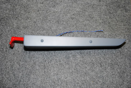
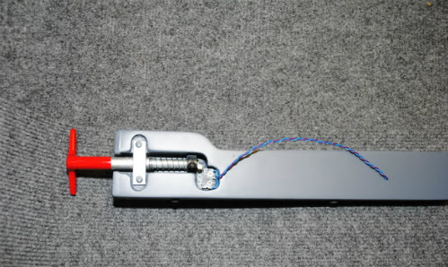
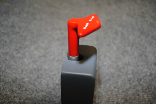
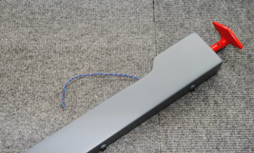
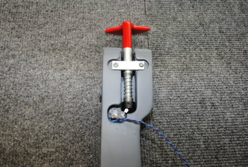
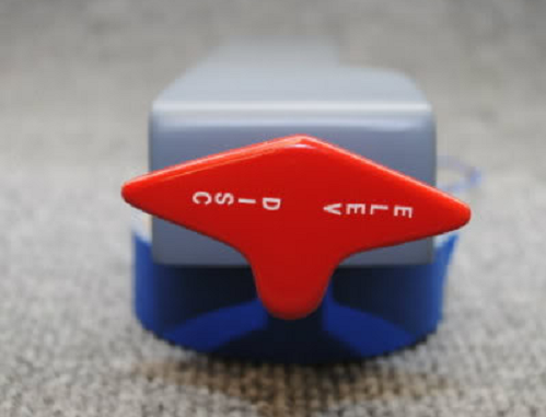
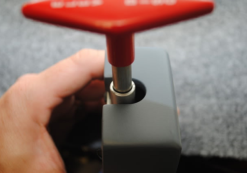
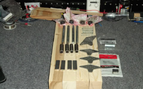
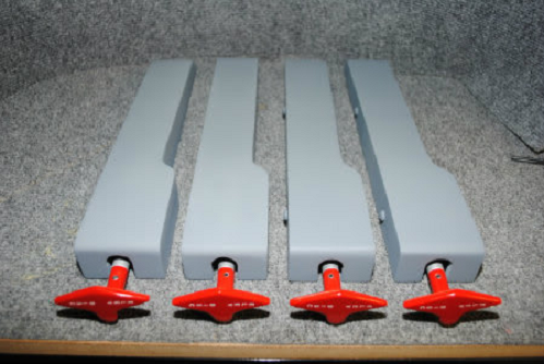
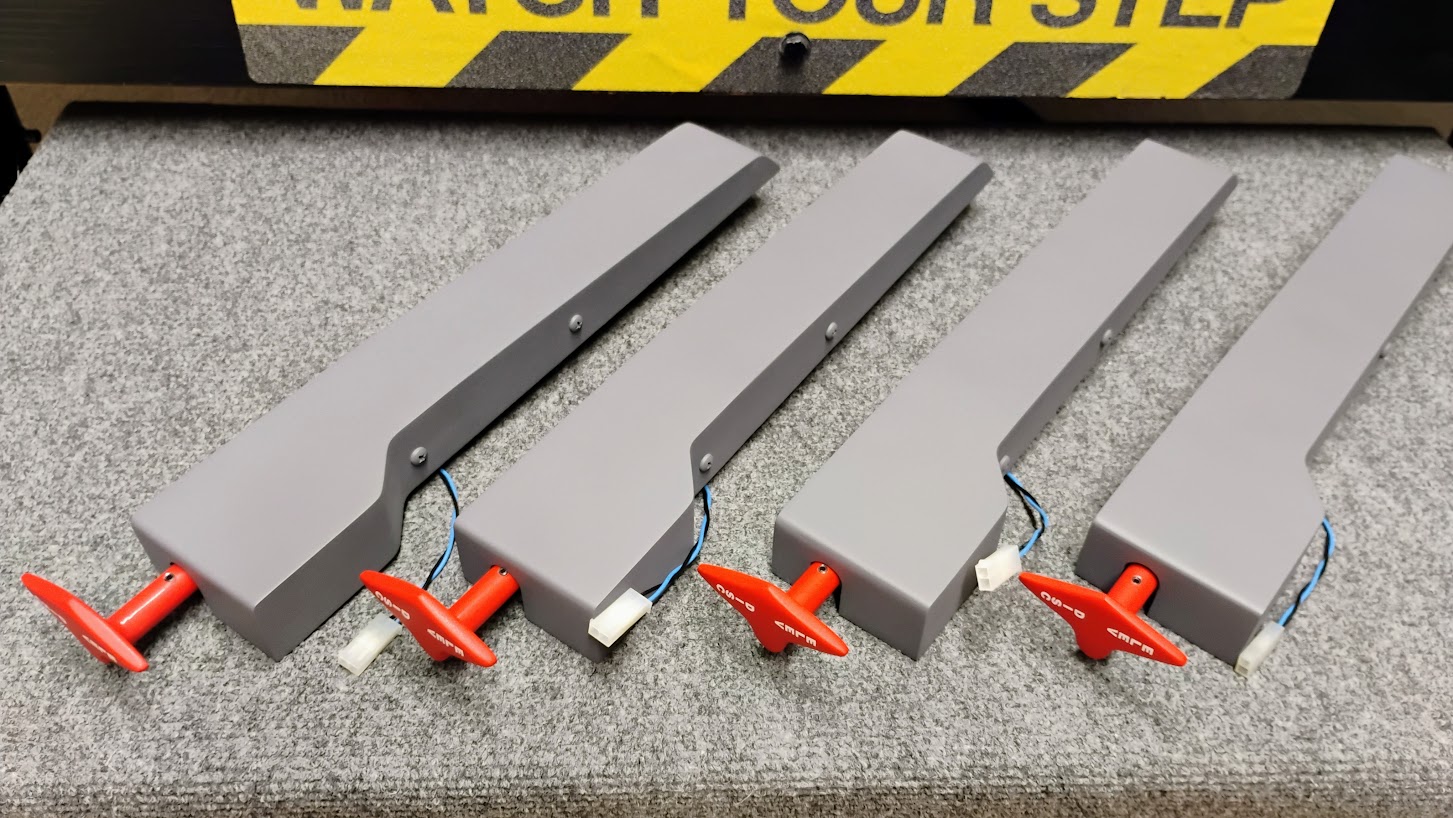
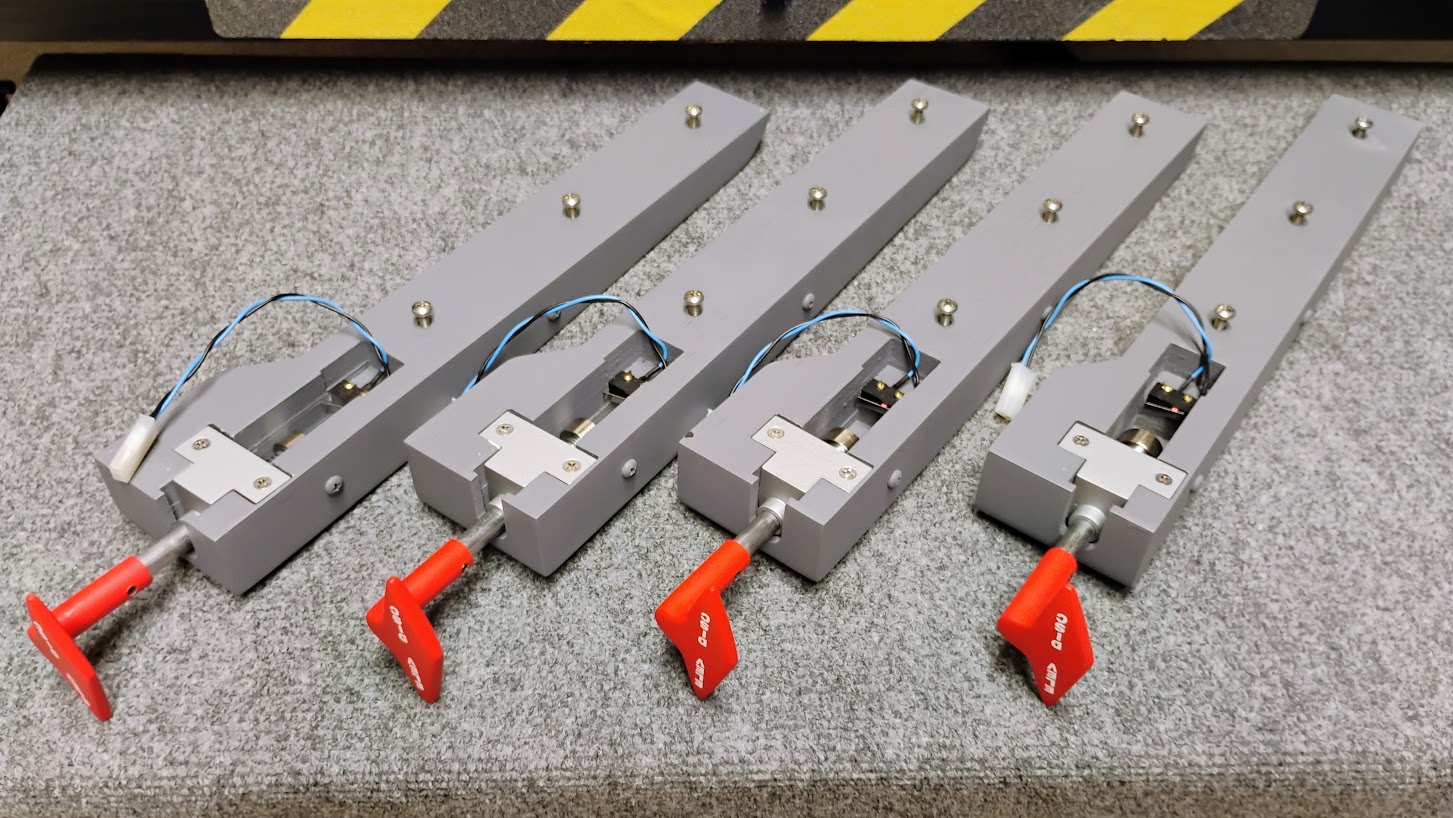
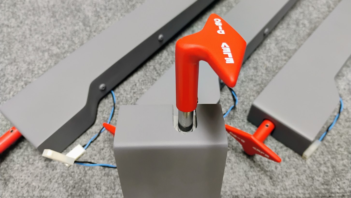
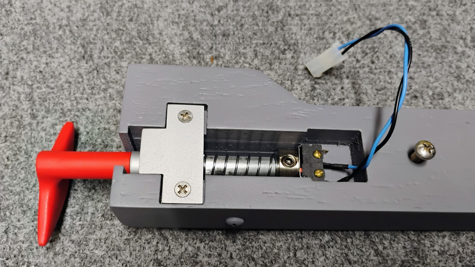
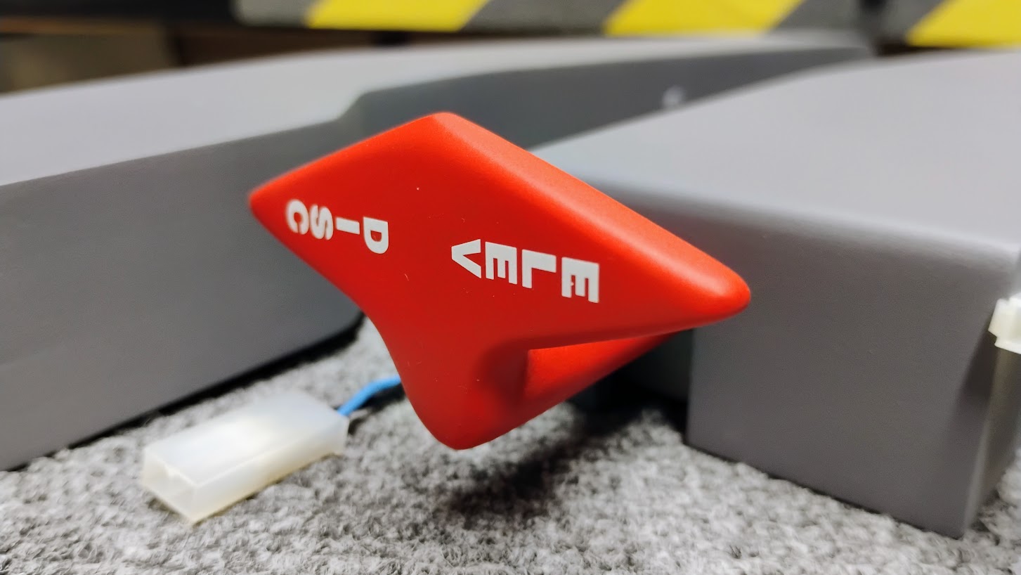
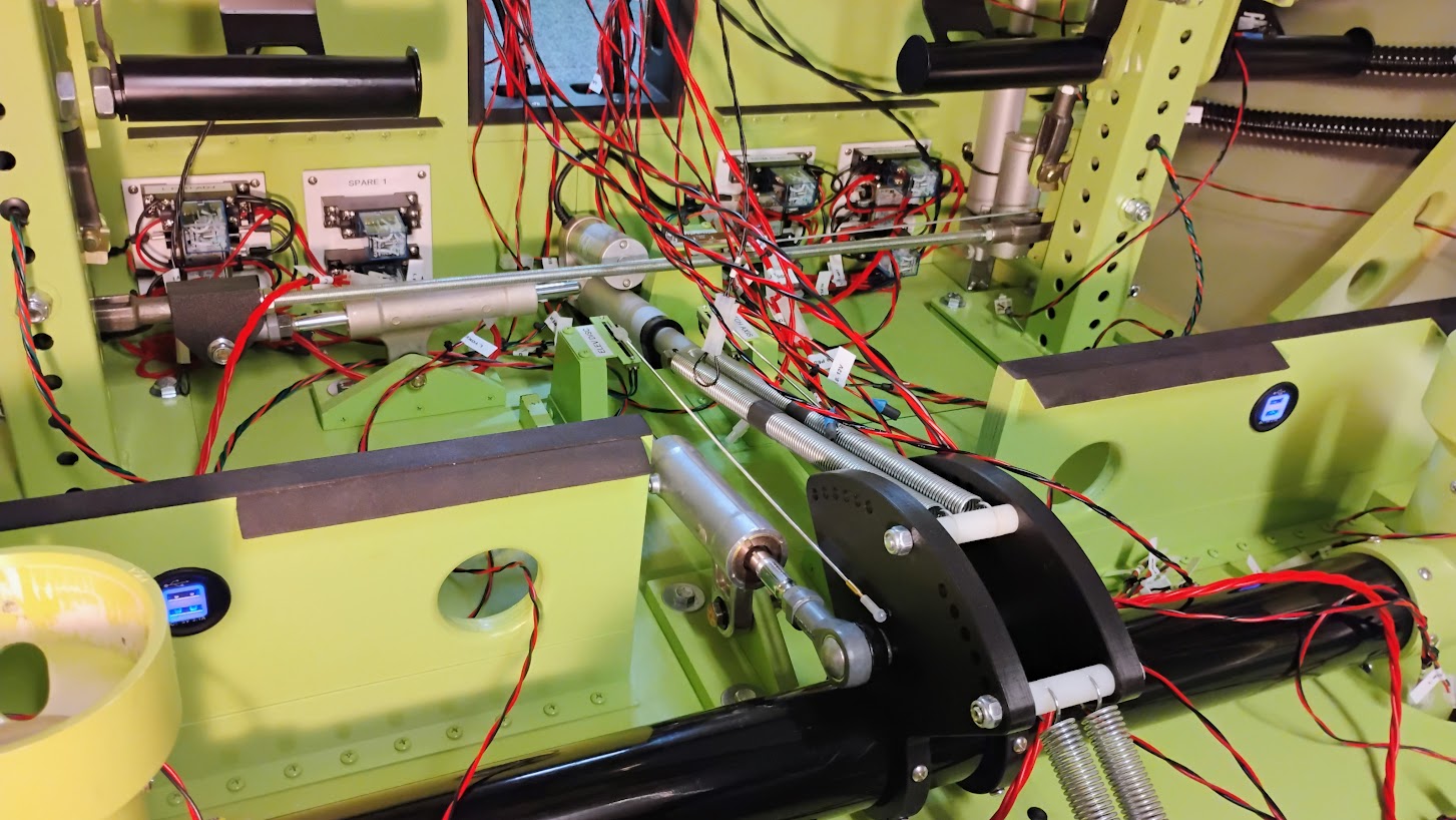
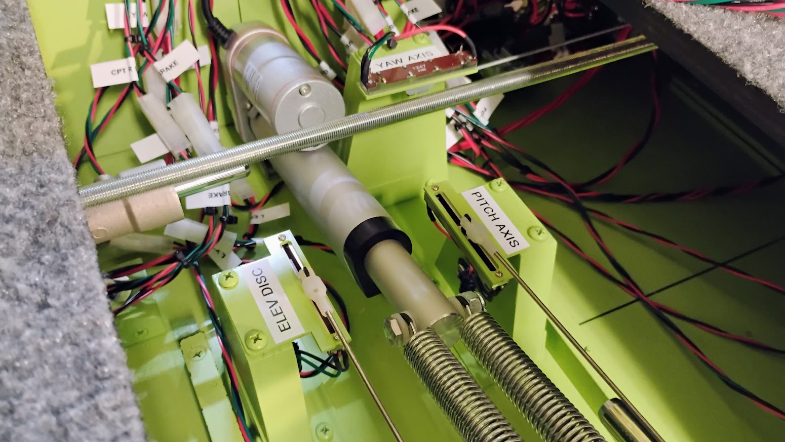
(Original thread started on 04-13-12 by Shane Barnes) I finally found some time to finish up on the elevator disconnect project that I have been working on. This is the new version of the elevator disconnect handle and switch mechanism that I designed. This design incorporates a switch that will detect if the elevator disconnect handle is not in the correct configuration for flight, and the handle pulls up and rotates to the left or right 90 degrees and locks in position as the real handle in the Lear 45. The handle is spring loaded and will return to its stowed position when turned back to center and released. This part is all handmade except for the switch, spring and locking collar. The box is made out of wood and routed to shape, sanded, smoothed and painted. I have discussed the possibility of Jason adding the CAS message in JET45 with Eric, and Jason is considering adding this feature to the software in a future update of JET45. The grey "box" was drawn by Ron along with a drawing of the "handle frame" that was cut out by Tom Goldberg with the water jet. I wanted to give credit to the guys that assisted in this project. Thanks guys! Side view of elevator disconnect box and handle: Back view of box showing switch and spring loaded switch mechanism: Close up of the pitch disconnect handle: I am considering making a few of these for sale if there is any interest in them. If interested email me at shaneb341 at roadrunner.com for pricing. UPDATE: Here is the finalized version of the pitch disconnect module. I made this one for Randy and if it meets his approval will be shipping out in the next few days. Here are a few photos of the completed module: (Posted by Ron Rollo on 04-23-12) Those parts look great Shane! I like the idea of having a switch inside the Pitch Disconnect module. You guys keep in mind that if you are going to include the Pitch trim module in your build you have to go with the short TQ port side access cover. If you have the larger port side cover version, it is not the end of the world. I was able to cut mine down to size and fill in the part of the opening in the TQ. It was a little time consuming though. (Posted by Shane Barnes on 05-14-12) A quick update . . Randy now has his pitch disconnect and parking brake assembly and I have started on four more pitch disconnect assemblies. Three will be going out to Mike, Alan and Eric and one will be going into my build (L45-007) Here is a photo of the parts awaiting cutting, welding, assembly and paint: hope to have these out to the guys soon if my real job does not interfere! I am close to finishing the four disconnects that I started working on May 14. I had an additional inquiry from Ronald so I will be making another PD in the future for myself . . customer comes first! Here are a few photos of the progress. They are finished and in final primer waiting the correct gunship grey color on the box portion of the assembly: (Posted by Ronald Pater on 07-08-12) I've received mine last week and they are absolutely awesome! Thanks Shane, good work! (Original thread started on 04-13-12 by Shane Barnes) I finally found some time to finish up on the elevator disconnect project that I have been working on. This is the new version of the elevator disconnect handle and switch mechanism that I designed. This design incorporates a switch that will detect if the elevator disconnect handle is not in the correct configuration for flight, and the handle pulls up and rotates to the left or right 90 degrees and locks in position as the real handle in the Lear 45. The handle is spring loaded and will return to its stowed position when turned back to center and released. This part is all handmade except for the switch, spring and locking collar. The box is made out of wood and routed to shape, sanded, smoothed and painted. I have discussed the possibility of Jason adding the CAS message in JET45 with Eric, and Jason is considering adding this feature to the software in a future update of JET45. The grey "box" was drawn by Ron along with a drawing of the "handle frame" that was cut out by Tom Goldberg with the water jet. I wanted to give credit to the guys that assisted in this project. Thanks guys! Side view of elevator disconnect box and handle: Back view of box showing switch and spring loaded switch mechanism: Close up of the pitch disconnect handle: I am considering making a few of these for sale if there is any interest in them. If interested email me at shaneb341 at roadrunner.com for pricing. UPDATE: Here is the finalized version of the pitch disconnect module. I made this one for Randy and if it meets his approval will be shipping out in the next few days. Here are a few photos of the completed module: (Posted by Ron Rollo on 04-23-12) Those parts look great Shane! I like the idea of having a switch inside the Pitch Disconnect module. You guys keep in mind that if you are going to include the Pitch trim module in your build you have to go with the short TQ port side access cover. If you have the larger port side cover version, it is not the end of the world. I was able to cut mine down to size and fill in the part of the opening in the TQ. It was a little time consuming though. (Posted by Shane Barnes on 05-14-12) A quick update . . Randy now has his pitch disconnect and parking brake assembly and I have started on four more pitch disconnect assemblies. Three will be going out to Mike, Alan and Eric and one will be going into my build (L45-007) Here is a photo of the parts awaiting cutting, welding, assembly and paint: hope to have these out to the guys soon if my real job does not interfere! I am close to finishing the four disconnects that I started working on May 14. I had an additional inquiry from Ronald so I will be making another PD in the future for myself . . customer comes first! Here are a few photos of the progress. They are finished and in final primer waiting the correct gunship grey color on the box portion of the assembly: (Posted by Ronald Pater on 07-08-12) I've received mine last week and they are absolutely awesome! Thanks Shane, good work! Hey guys, Shane and I have been working on a 2.0 version of the Elevator Disconnect box and handle. The only differences in this version over the previous is that this one is 100% to scale and the internal locking gate is made differently. We made enough to cover everyone who may need or want one. The internal locking gate is made of cast plastic via a CNC machine and strengthened with several 1/16" metal rods embedded into the plastic. To activate the micro switch, simply pull the handle and turn in either direction 90 degrees. Not that it matters because once mounted to the side of the TQ Pedestal you can't see it but the back side is cleaned up and squared away compared to the previous version. Last but not least, we use Dry Transfers for the artwork on the face of the handles. Dry Transfers are easy to use but fairly expensive especially if you are placing custom orders. Once they are in place they are hit with a light mist of flat clear to lock them in place and to remove the gloss finish of the red paint. The functionality of these handles are a physical extension of software implementation. They do not disconnect the control columns like what happens in the real Lear45. Once programmed, when the handle is pulled and the micro switch is triggered, a CAS message will appear advising "ELEV DISC". Additionally, we will use the micro switch to trigger a relay. Why would we want to trigger a relay? First you have to know if you have to pull this handle it means your elevators are jammed or stuck and you need to try to regain vertical control. In the real Lear45, when this handle is pulled, you are disconnecting the left and right elevators from each other at the control columns. The pilot's control column now controls the left side elevator and the Co Pilot's control column now only controls the right side elevator. In a worse case scenario, if one side is completely jammed, now the pilot opposite the jam has "some control" of vertical flight and they might survive the day. The idea of using a relay also requires using two pitch potentiometers on the lower control column crossover. It's hard to see in the photos below, right click and blow it up! A closer look at the two elevator pots. The one on the right marked "Pitch AXIS" is the primary pitch pot used during all normal flight. The one on the left marked "ELEV DISC" is the secondary pot used during abnormal flight conditions, simulating a jammed elevator. Now you can start to see why a relay is needed. Simply running the grounds from both pots to the relay will swap functionality from one pot to the other when the relay is triggered. Normally and nearly 100% of the time the "Pitch AXIS" pot will be used. A great illustration of how this is wired up is in the Jet45 AAS Systems Module document found HERE on page 65. NOTE: Additionally, the ROLL axis is set up in a similar manor where there are two pots and a relay that switches roll control from "Normal flight" to "Abnormal flight". See page 64 in the same document. So this covers the hardware aspects of the ELEV DISC box and why you would want one. The only other thing to do now is to set up the two pitch pots. The "Pitch Axis" pot will be set up to cover full range and emulate "normal flight" as best as you can set it up. The "ELEV DISC" pot will be set up severely "de tuned" from what normal is. This will replicate a jammed elevator condition making it feel sluggish or slow to respond compared to "normal flight". As you can see, there is a little more to the ELEV DISC box that something that sits on the side of the TQ Pedestal. It actually has some significant functionality! If you need a ELEV DISC box, let us know! Hey guys, Shane and I have been working on a 2.0 version of the Elevator Disconnect box and handle. The only differences in this version over the previous is that this one is 100% to scale and the internal locking gate is made differently. We made enough to cover everyone who may need or want one. The internal locking gate is made of cast plastic via a CNC machine and strengthened with several 1/16" metal rods embedded into the plastic. To activate the micro switch, simply pull the handle and turn in either direction 90 degrees. Not that it matters because once mounted to the side of the TQ Pedestal you can't see it but the back side is cleaned up and squared away compared to the previous version. Last but not least, we use Dry Transfers for the artwork on the face of the handles. Dry Transfers are easy to use but fairly expensive especially if you are placing custom orders. Once they are in place they are hit with a light mist of flat clear to lock them in place and to remove the gloss finish of the red paint. The functionality of these handles are a physical extension of software implementation. They do not disconnect the control columns like what happens in the real Lear45. Once programmed, when the handle is pulled and the micro switch is triggered, a CAS message will appear advising "ELEV DISC". Additionally, we will use the micro switch to trigger a relay. Why would we want to trigger a relay? First you have to know if you have to pull this handle it means your elevators are jammed or stuck and you need to try to regain vertical control. In the real Lear45, when this handle is pulled, you are disconnecting the left and right elevators from each other at the control columns. The pilot's control column now controls the left side elevator and the Co Pilot's control column now only controls the right side elevator. In a worse case scenario, if one side is completely jammed, now the pilot opposite the jam has "some control" of vertical flight and they might survive the day. The idea of using a relay also requires using two pitch potentiometers on the lower control column crossover. It's hard to see in the photos below, right click and blow it up! A closer look at the two elevator pots. The one on the right marked "Pitch AXIS" is the primary pitch pot used during all normal flight. The one on the left marked "ELEV DISC" is the secondary pot used during abnormal flight conditions, simulating a jammed elevator. Now you can start to see why a relay is needed. Simply running the grounds from both pots to the relay will swap functionality from one pot to the other when the relay is triggered. Normally and nearly 100% of the time the "Pitch AXIS" pot will be used. A great illustration of how this is wired up is in the Jet45 AAS Systems Module document found HERE on page 65. NOTE: Additionally, the ROLL axis is set up in a similar manor where there are two pots and a relay that switches roll control from "Normal flight" to "Abnormal flight". See page 64 in the same document. So this covers the hardware aspects of the ELEV DISC box and why you would want one. The only other thing to do now is to set up the two pitch pots. The "Pitch Axis" pot will be set up to cover full range and emulate "normal flight" as best as you can set it up. The "ELEV DISC" pot will be set up severely "de tuned" from what normal is. This will replicate a jammed elevator condition making it feel sluggish or slow to respond compared to "normal flight". As you can see, there is a little more to the ELEV DISC box that something that sits on the side of the TQ Pedestal. It actually has some significant functionality! If you need a ELEV DISC box, let us know!Elevator Disconnect Handle


2017-10-10