


(Original thread started on 07-26-11 by Ron Rollo) The real AoA gauge I thought I would start a thread on the AoA gauges that we will be working with. Thanks to DonnyRay, he has pointed me and a few others to this type of gauge. It is a APU Exhaust Temp gauge but it's innards will work perfectly for what we need it to do. I believe it is a DC meter, but DonnyRay would need to tell us more about the facts on it: It has it's own bracket with two screws that allow us to rotate the gauge 360 degrees. As a matter of fact, we will be rotating the gauge approximately 100 degrees to the left. If you look at some real photos of the AoA gauge, there are two small screws mounted on the face plate. When the gauge is not energized, the pointer has a resting position. If you look at this APU gauge and compare it to the real AoA gauge, they are in the same resting position. (After the APU gauge is turned in it's bracket.) The screw at the bottom is the adjusting screw and also tightens the gauge from turning. The screws are two different sizes for some reason. The upper one is a size 8 and the lower one is size 10. I had to go through all my photos to see if this is true in the Lear45 and in fact it is: So today I worked on getting them both mounted into the MIP. I had to open up the 2 inch holes just a tad and drilled slightly larger holes for the lower adjustment size 10 screws: In the future, I will take these APU exhaust gauges apart and put new faces inside them. I will probably repaint the top bezel ring to better match the MIP also. Here is a photo of the AoA gauge from the rear. It's fuzzy because of the windscreen: DonnyRay believes we will be able to interface these gauges with little to no issues as long as we can get a little software written for them. If anyone has thoughts on the AoA gauges, please share them here! (Posted by Vince C. on 07-27-11) Is the gauge driven by servos or stepper motors? I believe in both cases not only software but also some hardware is needed to control them. If it is a servo driven things are easier because a servo is nothing more than a pot and a light motor. Things changes a bit with steppers because you'll need to use a motor driver that supports the required power for the motor. (Posted by Eric Tomlin on 07-27-11) They are simply DC movement meters with about 300 degrees of movement. An analogue output card from Phidgets will drive these with a small software written to get the data out of FS via an SDK/Driver from Phidgets. Here is a video showing off a new AoA equipment by Safe Flight, the maker of the LJ45 AoA: https://youtu.be/bzLc-8brz2M (Posted by Ron Rollo on 07-27-11) Hey Vince, Eric is correct, it is basically a volt meter. Like the ones we use to test current. If we want to make the pointer move, all we would need to do is put a POT on it and some voltage. No motors, servos or stepper motors. (Posted by Vince C. ON 07-27-11) Okay, nice to know. Then this can be done with PoKeys too. Since this board as a 10bit analog output. Looking forward to the way you'll use them. (Posted by Eric Williams on 07-27-11) Just to put something out there, if you are going to basically rebuild those with new faces etc... why not just go to the local wrecking yard and grab and 90's or older instrument cluster with an appropriate sized fuel gauge etc? They work on the same principal. Very simple. All you CNC magicians could whip up a bezel and done deal. Most cluster gauges are commonly less than 1/2" deep too. Just another option for others perhaps. (Posted by Eric Tomlin on 07-27-11) Hi Eric, that's basically what's going on- Taking old DC10 APU gauges out and using those. They are on eBay for very cheap! All courtesy of DonnyRay Jones, our resident ex-NASA Electrical Engineer. (Posted by Ron Rollo on 07-30-11) Hey Eric G, I have not thought of auto gauges but I don't see why they would not also work. Probably less pins or connections on the back of them too. I even thought about making some from scratch. With that said, the ones that we have been pointed to by DonnyRay are cheap. You can find them for as little has $10. The bracket that the gauge nest in is more expensive! As a matter of fact, it is the bracket that makes it so easy, along with the fact that it is a DC meter. The next time I am at the auto parts store, I will take a look at the gauges to see how difficult they would be to work with. Has to be easier than rear AC parts. Shane, DonnyRay and I have been going back and forth about the connector barrels on the back side of the gauges. If we were lucky enough to actually find them, we would be unlucky enough to pay over $25 a piece for them! Anyway, here is what the back side of our future AoA gauges look like: And here a ten cent answer to the barrel plug problem we have: Basically, these are the female parts to the connectors I purchased from Mouser. I have over 1,000 of these little ladies and they are only 2 cents each. Obviously I still need to crimp the wires onto them, solder them and put wire shrink on them. It's going to work perfectly! (Posted by Shane Barnes on 07-31-11) For any of you that may be considering going the route that Ron and I have here is a link to a source for the gauge "clamp" that mounts behind the MIP. The part number for this clamp is MS 28042-1A in case you would like to search for a cheaper source for the clamp or watch eBay. http://avionicsmounts.com/products.php?cat=9 The cost at the above site is $24.62 per clamp so you may be able to find them cheaper this is the first site I found listing them. Also here is a link to one of the gauges currently for sale on eBay. I have bought from this seller several times with no problems. The part usually ships within three days. They have had several of these gauges for sale in the last month or so. See if they are still listing them HERE (Posted by Alan Norris on 10-15-11) I am about to order the Weston P/N 520423 Aircraft DC Load meter Indicator that you guys are using. That's the correct one right? I am going to see if I can fit the AoA face plate and plastic housing into it. Does anyone know how to determine what voltage drives the small solenoid? (Posted by Ron Rollo on 10-15-11) Hey Alan, that is the correct part number for the DC gauge. You may want to wait until one of the guys gets around to making the correct face plate instead of the one in the AoA gauge that you have as it is not correct for the Lear 45. I plan on waiting and in fact Ron and I discussed the face plate awhile back and some potential ways to make it and I think Ron has some ideas on this. This may be one of those parts that Ron takes on as he has a talent for making parts like the gauge face, I think he likes the challenge! I think if he does this may be one of those projects that he takes on in the future after the more immediate parts are finished. What I mean by that is that some areas like the AoA need more work but they are not actually needed to get up and flying and are parts easily worked on once the sim is up and going. I have purchased the DC gauge and have it mounted in my MIP of course right now it is just filling up the hole until we get some programming that will interface it with FS. (Posted by Alan Norris on 10-16-11) Shane and Ron, I was referring to the actual dial face itself not the bezel. Is that what you are talking about? I just snagged a 2" gauge clamp for $11.99. Unfortunately is was the last one they had. However there are others to be had here: http://www.keenzo.com/showproduct.asp?ID=1276573 (Posted by Rick Trantham on 09-13-12) Hey guys, I just got a pair of those DC volt gauges and have been playing around with them. I did some pin testing using 5 volts from a PC power supply. I got the lighting to work and the needle moving. 5 volts pegs the needle, so obviously it will need only a fraction of that to function. I'm gonna get a Phidgets Analog board and try to work up something that pulls the AoA data from FSX using SimConnect and translates that to a voltage. I'll keep y'all updated on my progress. UPDATE: I got the Phidgets Analog card and now have the gauge working with the AoA data using SimConnect. I need to do some more fiddling with the data, but so far it seems to be working well. I need to clean up the software code and add a couple of important features, but it's working great. Here is a pin connection diagram. I'm hoping to have the software in a beta version in the next couple of weeks. Here's the pin out. I only tested the lighting using 5 volts. Top of gauge \ . pos | ------------- lighting . . neg / . . pos \ . neg | ------------ movement / (Posted by Ron Rollo on 11-04-12) Thanks Rick. Have you had one of these gauges apart yet? And if so, have you looked into what it is going to take to swap out the face so that the art work matches what the AoA would look like? I know that DonnyRay can probably take one of these things apart in his sleep. It would be cool if we had a short tutorial of how to get into these little guys without wrecking them. That was another thing that DonnyRay mentioned is that you have to be careful taking them apart. I believe he said that there was a few springs in them and if they get loose you may never find them again! (Posted by Alan Norris on 11-05-12) I have taken mine apart and I can tell you that it will be fairly easy to swap the gauge faces, but it'll be a major undertaking to swap the needles. The DC load gauge has a cone shaped clear plastic backing to the face and there are three grain of wheat bulbs on a removable card at the top of the gauge that illuminates this cone. The face on the DC load gauge is attached to the clear plastic cone with two small screws at 5 and 7 o'clock. I drilled two small holes in the AoA gauge face at the same locations and used the screws to attach it to the plastic cone. The needle on the AoA gauge is attached in a totally different fashion to that of the DC load gauge. As I was not concerned with having a working gauge I just cut the wire that the needle is attached to and glued my AoA needle in its place. Someone will have to investigate this area in more detail to see what is required to swap it over so that it works. Here's a photo of mine and you can just make out the screw heads. They need some flat black paint as the light is bleeding through: By the way, the DC Load gauge comes apart fairly easily. The body of the gauge is attached to the housing with four small Phillips head screws around the circumference. Before removing the body take out the lighting card. It is attached to the housing with two screws. Take some needle nosed pliers and gently pull the card out -- there are two flat spring and they make contact with the card to provide current. After removing this card then pull the body out of the housing. Now the AoA gauge is another matter as the whole thing is sealed at the front with some sort of mastic. I just about destroyed the thing getting it apart but all I wanted was the gauge face and needle. (Original thread started on 07-26-11 by Ron Rollo) The real AoA gauge I thought I would start a thread on the AoA gauges that we will be working with. Thanks to DonnyRay, he has pointed me and a few others to this type of gauge. It is a APU Exhaust Temp gauge but it's innards will work perfectly for what we need it to do. I believe it is a DC meter, but DonnyRay would need to tell us more about the facts on it: It has it's own bracket with two screws that allow us to rotate the gauge 360 degrees. As a matter of fact, we will be rotating the gauge approximately 100 degrees to the left. If you look at some real photos of the AoA gauge, there are two small screws mounted on the face plate. When the gauge is not energized, the pointer has a resting position. If you look at this APU gauge and compare it to the real AoA gauge, they are in the same resting position. (After the APU gauge is turned in it's bracket.) The screw at the bottom is the adjusting screw and also tightens the gauge from turning. The screws are two different sizes for some reason. The upper one is a size 8 and the lower one is size 10. I had to go through all my photos to see if this is true in the Lear45 and in fact it is: So today I worked on getting them both mounted into the MIP. I had to open up the 2 inch holes just a tad and drilled slightly larger holes for the lower adjustment size 10 screws: In the future, I will take these APU exhaust gauges apart and put new faces inside them. I will probably repaint the top bezel ring to better match the MIP also. Here is a photo of the AoA gauge from the rear. It's fuzzy because of the windscreen: DonnyRay believes we will be able to interface these gauges with little to no issues as long as we can get a little software written for them. If anyone has thoughts on the AoA gauges, please share them here! (Posted by Vince C. on 07-27-11) Is the gauge driven by servos or stepper motors? I believe in both cases not only software but also some hardware is needed to control them. If it is a servo driven things are easier because a servo is nothing more than a pot and a light motor. Things changes a bit with steppers because you'll need to use a motor driver that supports the required power for the motor. (Posted by Eric Tomlin on 07-27-11) They are simply DC movement meters with about 300 degrees of movement. An analogue output card from Phidgets will drive these with a small software written to get the data out of FS via an SDK/Driver from Phidgets. Here is a video showing off a new AoA equipment by Safe Flight, the maker of the LJ45 AoA: (Posted by Ron Rollo on 07-27-11) Hey Vince, Eric is correct, it is basically a volt meter. Like the ones we use to test current. If we want to make the pointer move, all we would need to do is put a POT on it and some voltage. No motors, servos or stepper motors. (Posted by Vince C. ON 07-27-11) Okay, nice to know. Then this can be done with PoKeys too. Since this board as a 10bit analog output. Looking forward to the way you'll use them. (Posted by Eric Williams on 07-27-11) Just to put something out there, if you are going to basically rebuild those with new faces etc... why not just go to the local wrecking yard and grab and 90's or older instrument cluster with an appropriate sized fuel gauge etc? They work on the same principal. Very simple. All you CNC magicians could whip up a bezel and done deal. Most cluster gauges are commonly less than 1/2" deep too. Just another option for others perhaps. (Posted by Eric Tomlin on 07-27-11) Hi Eric, that's basically what's going on- Taking old DC10 APU gauges out and using those. They are on eBay for very cheap! All courtesy of DonnyRay Jones, our resident ex-NASA Electrical Engineer. (Posted by Ron Rollo on 07-30-11) Hey Eric G, I have not thought of auto gauges but I don't see why they would not also work. Probably less pins or connections on the back of them too. I even thought about making some from scratch. With that said, the ones that we have been pointed to by DonnyRay are cheap. You can find them for as little has $10. The bracket that the gauge nest in is more expensive! As a matter of fact, it is the bracket that makes it so easy, along with the fact that it is a DC meter. The next time I am at the auto parts store, I will take a look at the gauges to see how difficult they would be to work with. Has to be easier than rear AC parts. Shane, DonnyRay and I have been going back and forth about the connector barrels on the back side of the gauges. If we were lucky enough to actually find them, we would be unlucky enough to pay over $25 a piece for them! Anyway, here is what the back side of our future AoA gauges look like: And here a ten cent answer to the barrel plug problem we have: Basically, these are the female parts to the connectors I purchased from Mouser. I have over 1,000 of these little ladies and they are only 2 cents each. Obviously I still need to crimp the wires onto them, solder them and put wire shrink on them. It's going to work perfectly! (Posted by Shane Barnes on 07-31-11) For any of you that may be considering going the route that Ron and I have here is a link to a source for the gauge "clamp" that mounts behind the MIP. The part number for this clamp is MS 28042-1A in case you would like to search for a cheaper source for the clamp or watch eBay. http://avionicsmounts.com/products.php?cat=9 The cost at the above site is $24.62 per clamp so you may be able to find them cheaper this is the first site I found listing them. Also here is a link to one of the gauges currently for sale on eBay. I have bought from this seller several times with no problems. The part usually ships within three days. They have had several of these gauges for sale in the last month or so. See if they are still listing them HERE (Posted by Alan Norris on 10-15-11) I am about to order the Weston P/N 520423 Aircraft DC Load meter Indicator that you guys are using. That's the correct one right? I am going to see if I can fit the AoA face plate and plastic housing into it. Does anyone know how to determine what voltage drives the small solenoid? (Posted by Ron Rollo on 10-15-11) Hey Alan, that is the correct part number for the DC gauge. You may want to wait until one of the guys gets around to making the correct face plate instead of the one in the AoA gauge that you have as it is not correct for the Lear 45. I plan on waiting and in fact Ron and I discussed the face plate awhile back and some potential ways to make it and I think Ron has some ideas on this. This may be one of those parts that Ron takes on as he has a talent for making parts like the gauge face, I think he likes the challenge! I think if he does this may be one of those projects that he takes on in the future after the more immediate parts are finished. What I mean by that is that some areas like the AoA need more work but they are not actually needed to get up and flying and are parts easily worked on once the sim is up and going. I have purchased the DC gauge and have it mounted in my MIP of course right now it is just filling up the hole until we get some programming that will interface it with FS. (Posted by Alan Norris on 10-16-11) Shane and Ron, I was referring to the actual dial face itself not the bezel. Is that what you are talking about? I just snagged a 2" gauge clamp for $11.99. Unfortunately is was the last one they had. However there are others to be had here: http://www.keenzo.com/showproduct.asp?ID=1276573 (Posted by Rick Trantham on 09-13-12) Hey guys, I just got a pair of those DC volt gauges and have been playing around with them. I did some pin testing using 5 volts from a PC power supply. I got the lighting to work and the needle moving. 5 volts pegs the needle, so obviously it will need only a fraction of that to function. I'm gonna get a Phidgets Analog board and try to work up something that pulls the AoA data from FSX using SimConnect and translates that to a voltage. I'll keep y'all updated on my progress. UPDATE: I got the Phidgets Analog card and now have the gauge working with the AoA data using SimConnect. I need to do some more fiddling with the data, but so far it seems to be working well. I need to clean up the software code and add a couple of important features, but it's working great. Here is a pin connection diagram. I'm hoping to have the software in a beta version in the next couple of weeks. Here's the pin out. I only tested the lighting using 5 volts. Top of gauge \ . pos | ------------- lighting . . neg / . . pos \ . neg | ------------ movement / (Posted by Ron Rollo on 11-04-12) Thanks Rick. Have you had one of these gauges apart yet? And if so, have you looked into what it is going to take to swap out the face so that the art work matches what the AoA would look like? I know that DonnyRay can probably take one of these things apart in his sleep. It would be cool if we had a short tutorial of how to get into these little guys without wrecking them. That was another thing that DonnyRay mentioned is that you have to be careful taking them apart. I believe he said that there was a few springs in them and if they get loose you may never find them again! (Posted by Alan Norris on 11-05-12) I have taken mine apart and I can tell you that it will be fairly easy to swap the gauge faces, but it'll be a major undertaking to swap the needles. The DC load gauge has a cone shaped clear plastic backing to the face and there are three grain of wheat bulbs on a removable card at the top of the gauge that illuminates this cone. The face on the DC load gauge is attached to the clear plastic cone with two small screws at 5 and 7 o'clock. I drilled two small holes in the AoA gauge face at the same locations and used the screws to attach it to the plastic cone. The needle on the AoA gauge is attached in a totally different fashion to that of the DC load gauge. As I was not concerned with having a working gauge I just cut the wire that the needle is attached to and glued my AoA needle in its place. Someone will have to investigate this area in more detail to see what is required to swap it over so that it works. Here's a photo of mine and you can just make out the screw heads. They need some flat black paint as the light is bleeding through: By the way, the DC Load gauge comes apart fairly easily. The body of the gauge is attached to the housing with four small Phillips head screws around the circumference. Before removing the body take out the lighting card. It is attached to the housing with two screws. Take some needle nosed pliers and gently pull the card out -- there are two flat spring and they make contact with the card to provide current. After removing this card then pull the body out of the housing. Now the AoA gauge is another matter as the whole thing is sealed at the front with some sort of mastic. I just about destroyed the thing getting it apart but all I wanted was the gauge face and needle. (Posted by Ron Rollo on 11-05-12) Your AoA face looked very familiar. But now I see it is a real one swapped over to a DC load gauge. I'm looking forward to working on these things! Here is a photo of the real face plate of the AoA found in the Lear45: It is worth saying again for the guys reading through this thread, you MUST start with a DC load gauge if you want a working AoA in your Lear45 sim. With a little luck, you can find DC Load gauges for under $20 each on sites like eBay. (Posted by Rick Trantham on 11-05-12) I haven't been brave enough to take one apart yet. I've got enough half-built items around here anyway. I was thinking we might be able to extend the needle by making one out of plastic and gluing it on top of the existing needle. I just don't know how that will affect the lighting. (Posted by Alan Norris on 11-06-12) I don't think it will be possible to glue the AoA needle onto the DC gauge needle. The reason I say that is because when I put the AoA face onto the DC backer there was very little room between it and the glass. The AoA needle is quite thick and when I put the assembly in the DC case the needle was tight against the glass. In my opinion you will be better off to leave the DC gauge needle in place and just swap the faces. Okay I know it doesn't have the "pure" Lear45 AoA gauge look but I think it will be a small compromise that will save you hours of frustration and possibly damage to a working gauge. Here is a shot of the DC Load gauge face plate. Although the AoA needle is about the same thickness, the DC Load gauge face plate has a recess where the needle rotates so the face plate can be tight against the glass. The AoA faceplate doesn't have that. You may be able to shave the AoA needle so that it's thinner. The DC gauge needle is attached to a thin wire that goes behind the clear cone. Getting the old needle off without bending this wire will be a challenge but I know you're up to it: (Posted by Rick Trantham on 12-29-12) Hey guys! The AoA software is complete. I've been using it for awhile and I think all of the bugs are out. If you have questions, you can contact me using the info available here at the hangar, or use the email address listed in the documentation. (Posted by Shane Barnes on 12-29-12) Great job! Thanks for taking this project on and sharing with us! Looking forward to using this in my build once I get to that point! A few years ago we had not even really considered this gauge being functional in our builds. It amazes me what our members are capable of doing! UPDATE: My Phidgets card came in a few days ago and I was able to get the DC load gauges (future AoA gauges) interfaced with FSX using your software. It works great! Really awesome seeing real gauges working with FSX. Thanks for the continued work on this Rick, it really adds to the build. Not to long ago we thought these would just be dummy gauges that lit up! (Posted by Manfred on 01-13-13) I've had a search for DC load gauges with no luck on eBay. Are ordinary car gauges the same thing? There seem to be a lot of those on eBay. The temperature ones look like they have enough sweep, unlike the fuel ones. I guess it would also depend on the dimensions. (Posted by Alan Norris on 01-13-13) I know that Shane has the DC gauge working but has anyone had any luck with getting the AoA gauge face and needle to actually fit in the DC Load gauge case. I posted earlier that I have mine installed but the needle is inoperable as I found it impossible to remove the DC gauge needle without damaging it and the AoA needle was so close to the glass that even if I did manage to swap it out it wouldn't have the clearance to move. (Posted by Shane Barnes on 01-13-13) Hey Alan, what AoA gauge face are you trying to get to fit in the DC load gauge case? As far as I know, no one has made the AoA face yet. Ron was talking about looking into this at some point this year but I don't think he has actually started on it. I would say best case scenario here is that a custom faceplate is made that looks the part. (Posted by Rick Trantham on 01-13-13) You're welcome Shane! I'm happy to help make our sims as close to reality as possible. As for using other gauges, you should be able to use any gauge that can be controlled by a voltage. Here's a link to the Phidgets card you need to use with the software: http://www.phidgets.com/products.php?category=0&product_id=1002_0 Here is a short video where I am testing the Analogix software and a mock up of a simulated Learjet AOA gauge using a Phidgets Advanced Servo controller card and TowerPro micro servo. I'm also testing an optional vox stall warning that is triggered at .8 AOA. FSX only triggers a stall warning at 1.0 AOA. https://youtu.be/mD06IwCsUA4 (Posted by Alan Norris on 01-13-13) Shane, the face from the Lear AoA gauge. I have one that is similar (mine had the flag that is not on the Lear one but is very similar). If someone is going to make one from scratch then they need to look at the clearances needed in the DC gauge case. I would be more concerned with getting the AoA needle to work in the DC case. The DC gauge has a totally different needle and (if my DC gauge is typical) it is almost impossible to remove it without damaging the connection. (Posted by Ron Rollo on 03-12-13) I purchased my Phidgets card a few weeks ago and have it mounted to the avionics bay. Hopefully sometime this year I can follow Rick's lead and get my AOA gauges (DC load meters) working: You can read more about the Phidgets interface cards here: (Posted by Randy Buchanan on 03-13-13) That's cool. The last time Shane told me to buy something I got a really nice FMC on eBay at a good price. I hope to have a suggestion for your AoA, but I have to test the idea to make sure it works first. (Posted by Ron Rollo on 03-15-13) Hey guys, Terry found a real Lear45 AoA somewhere on the net and had it shipped to me because the seller did not ship down under. To my surprise, the AoA found in the Lear45 appears to be a DC load meter, the exact kind we need in order to take advantage of Rick's efforts and the Phidgets card approach. What this means is that if your lucky enough to find a pair, you will not need to go through the trouble of modifying the face of another DC load meter. Take a look at these photos: The one on the left is the real Lear45 AoA. The one on the right is a EXH TEMP APU gauge that I plan to modify. By the way, the big black circle in the middle of the APU gauge is a lamp shade. It is not attached to the needle. As a matter of fact, the "T" on the left side of the plate is the Lamp shade base. We might be able to make a replica of this part to help mimic the real Lear45 AoA: Each of these have six pins in the plug, although they are a different pattern. They are made by two different companies: Also a heads up. DonnyRay advised me that he is working on a face replacement tutorial. So don't destroy your DC load meters until you see what he has to say. I have seen a sneak peek and they look good! (Posted by Terry Collins on 03-16-13) Ron, from what I can see the real AoA meter runs on 28 volts which is a bit inconvenient for us builders. (Posted by Eric Williams on 03-16-13) Just a thought here guys- you may want to look into PoKeys and a basic servo. FSSymphony can calibrate/operate them from within the free program. Just need the needle and the face plate. (Posted by Ron Rollo on 11-05-12) Your AoA face looked very familiar. But now I see it is a real one swapped over to a DC load gauge. I'm looking forward to working on these things! Here is a photo of the real face plate of the AoA found in the Lear45: It is worth saying again for the guys reading through this thread, you MUST start with a DC load gauge if you want a working AoA in your Lear45 sim. With a little luck, you can find DC Load gauges for under $20 each on sites like eBay. (Posted by Rick Trantham on 11-05-12) I haven't been brave enough to take one apart yet. I've got enough half-built items around here anyway. I was thinking we might be able to extend the needle by making one out of plastic and gluing it on top of the existing needle. I just don't know how that will affect the lighting. (Posted by Alan Norris on 11-06-12) I don't think it will be possible to glue the AoA needle onto the DC gauge needle. The reason I say that is because when I put the AoA face onto the DC backer there was very little room between it and the glass. The AoA needle is quite thick and when I put the assembly in the DC case the needle was tight against the glass. In my opinion you will be better off to leave the DC gauge needle in place and just swap the faces. Okay I know it doesn't have the "pure" Lear45 AoA gauge look but I think it will be a small compromise that will save you hours of frustration and possibly damage to a working gauge. Here is a shot of the DC Load gauge face plate. Although the AoA needle is about the same thickness, the DC Load gauge face plate has a recess where the needle rotates so the face plate can be tight against the glass. The AoA faceplate doesn't have that. You may be able to shave the AoA needle so that it's thinner. The DC gauge needle is attached to a thin wire that goes behind the clear cone. Getting the old needle off without bending this wire will be a challenge but I know you're up to it: (Posted by Rick Trantham on 12-29-12) Hey guys! The AoA software is complete. I've been using it for awhile and I think all of the bugs are out. If you have questions, you can contact me using the info available here at the hangar, or use the email address listed in the documentation. (Posted by Shane Barnes on 12-29-12) Great job! Thanks for taking this project on and sharing with us! Looking forward to using this in my build once I get to that point! A few years ago we had not even really considered this gauge being functional in our builds. It amazes me what our members are capable of doing! UPDATE: My Phidgets card came in a few days ago and I was able to get the DC load gauges (future AoA gauges) interfaced with FSX using your software. It works great! Really awesome seeing real gauges working with FSX. Thanks for the continued work on this Rick, it really adds to the build. Not to long ago we thought these would just be dummy gauges that lit up! (Posted by Manfred on 01-13-13) I've had a search for DC load gauges with no luck on eBay. Are ordinary car gauges the same thing? There seem to be a lot of those on eBay. The temperature ones look like they have enough sweep, unlike the fuel ones. I guess it would also depend on the dimensions. (Posted by Alan Norris on 01-13-13) I know that Shane has the DC gauge working but has anyone had any luck with getting the AoA gauge face and needle to actually fit in the DC Load gauge case. I posted earlier that I have mine installed but the needle is inoperable as I found it impossible to remove the DC gauge needle without damaging it and the AoA needle was so close to the glass that even if I did manage to swap it out it wouldn't have the clearance to move. (Posted by Shane Barnes on 01-13-13) Hey Alan, what AoA gauge face are you trying to get to fit in the DC load gauge case? As far as I know, no one has made the AoA face yet. Ron was talking about looking into this at some point this year but I don't think he has actually started on it. I would say best case scenario here is that a custom faceplate is made that looks the part. (Posted by Rick Trantham on 01-13-13) You're welcome Shane! I'm happy to help make our sims as close to reality as possible. As for using other gauges, you should be able to use any gauge that can be controlled by a voltage. Here's a link to the Phidgets card you need to use with the software: http://www.phidgets.com/products.php?category=0&product_id=1002_0 Here is a short video where I am testing the Analogix software and a mock up of a simulated Learjet AOA gauge using a Phidgets Advanced Servo controller card and TowerPro micro servo. I'm also testing an optional vox stall warning that is triggered at .8 AOA. FSX only triggers a stall warning at 1.0 AOA. (Posted by Alan Norris on 01-13-13) Shane, the face from the Lear AoA gauge. I have one that is similar (mine had the flag that is not on the Lear one but is very similar). If someone is going to make one from scratch then they need to look at the clearances needed in the DC gauge case. I would be more concerned with getting the AoA needle to work in the DC case. The DC gauge has a totally different needle and (if my DC gauge is typical) it is almost impossible to remove it without damaging the connection. (Posted by Ron Rollo on 03-12-13) I purchased my Phidgets card a few weeks ago and have it mounted to the avionics bay. Hopefully sometime this year I can follow Rick's lead and get my AOA gauges (DC load meters) working: You can read more about the Phidgets interface cards here: (Posted by Randy Buchanan on 03-13-13) That's cool. The last time Shane told me to buy something I got a really nice FMC on eBay at a good price. I hope to have a suggestion for your AoA, but I have to test the idea to make sure it works first. (Posted by Ron Rollo on 03-15-13) Hey guys, Terry found a real Lear45 AoA somewhere on the net and had it shipped to me because the seller did not ship down under. To my surprise, the AoA found in the Lear45 appears to be a DC load meter, the exact kind we need in order to take advantage of Rick's efforts and the Phidgets card approach. What this means is that if your lucky enough to find a pair, you will not need to go through the trouble of modifying the face of another DC load meter. Take a look at these photos: The one on the left is the real Lear45 AoA. The one on the right is a EXH TEMP APU gauge that I plan to modify. By the way, the big black circle in the middle of the APU gauge is a lamp shade. It is not attached to the needle. As a matter of fact, the "T" on the left side of the plate is the Lamp shade base. We might be able to make a replica of this part to help mimic the real Lear45 AoA: Each of these have six pins in the plug, although they are a different pattern. They are made by two different companies: Also a heads up. DonnyRay advised me that he is working on a face replacement tutorial. So don't destroy your DC load meters until you see what he has to say. I have seen a sneak peek and they look good! (Posted by Terry Collins on 03-16-13) Ron, from what I can see the real AoA meter runs on 28 volts which is a bit inconvenient for us builders. (Posted by Eric Williams on 03-16-13) Just a thought here guys- you may want to look into PoKeys and a basic servo. FSSymphony can calibrate/operate them from within the free program. Just need the needle and the face plate. (Posted by DonnyRay Jones on 03-18-13) Ya'll are making this way harder than it is. Modifying a DC load gauge consists of changing the face plate - that's all. No disassembly of the meter innards, no removing the needle, etc. The reason we picked on a DC load gauge for this is that (1) the real AoA contains a simple DC meter movement nearly identical to the DC load gauge, and (2) DC load gauges were / are readily available for about twenty bucks, and (3) you can drive a DC meter directly from any buffered D/A output card without further ado. The real Lear AoA does not require 28 volts for operation. The AoA *system* runs on 28 volts, but the indicator itself is nothing more than a simple dc meter. The DC load gauge does not require 28 volts. Or 12 volts. Or 5 volts. It's just a plain vanilla dc meter movement - just like the real AoA. Last week I noticed that this thread seemed to be going off in the weeds so I sat down with a DC load gauge and modified it to an AoA and took photos along the way to illustrate how it's done. I need to write it up and post it here. It's an easy mod that does not require special tools. Ron has seen a photo of the real AoA sitting next to the modified DC load gauge. I'll try to get this posted here in a few days so you'll at least have another option before you go off chasing more difficult solutions. How To Convert a D.C. Load Gauge to an Angle-of-Attack Indicator: First – select an appropriate gauge for modification. Many different types of aircraft indicators (gauges) can be found on e-bay and other surplus sources. For our purposes here - modifying them for use in a sim - three factors are important: 1. It needs to be a simple DC-operated current meter. This is the most basic form of meter. The “1 milliampere full scale” Weston is very common and easy to use. AVOID indicators that do not contain a basic DC meter because they are either difficult to modify or require special driving circuitry. For example, %RPM indicators are not meters at all. They're actually little 3 phase variable frequency motors that are driven by a tach generator mounted on the engine. We could design an interface to drive this kind of meter but it might cost several hundred dollars. Certain types of indicators display measured parameters that vary rapidly. Hydraulic pressure can vary so wildly that a conventional meter pointer will appear to be vibrating. These kinds of indicators are damped to smooth the displayed reading. Attempts to remove the damping mechanism or circuitry often result in ruining the meter movement. Surplus military AoA indicators aren't meters either. Those are selsyn indicators. (See Wikipedia “synchro” for a definition and look for the word “selsyn” in the text.) Many round indicators which display the POSITION of something (flaps, slats, rudder trim, etc.) are of this type and are unsuitable for simple modification. 2. Select a meter with the required needle deflection for the instrument you are trying to build. For example, if you're doing an AoA you want a meter with about 200 degrees of rotation. Many other round meters only provide about 180 degrees of deflection. 3. Select a meter with a flat face. Many indicators use a face which consists of an outer ring for the scale and an inner disk on which the pointer is mounted (or printed!). It's hard to make new artwork rings for these meters, but you can overlay the original artwork with a replacement without damaging the meter movement. You *DO NOT EVER* want to try and remove the POINTER or any part of the meter mechanical movement. That's a recipe for producing a small pile of useless precision parts. I’ve had good success modifying the Weston DC load meters. These meters do not have flat faces, but they’re readily available and inexpensive. The mod described here is fairly easy to do and does not require special tools. It makes a pretty darn good AoA. If you eventually find real AoAs they’ll work in the same circuit as this modified unit because the real AoA has essentially the same innards as the Weston DC load meter! So....enough talk....let’s go modify a DC Load Meter! Here is a DC Load Meter next to a genuine Lear AoA. Rotate both meters so that the pointers are straight up: Print out a new AoA meter face to use as a template. The face will be used for checking the angular travel of the pointer and also as a fit template. Tip: You’re likely to print several of these until you get the scale correct so use a cheap print method at first. Once you figure out the scale, etc., you can print the new meter face in color on the desired medium. Use the new meter face to check that the candidate meter has sufficient pointer travel end to end: Remove the case. DO NOT remove the screws on the back connector panel. Remove the 4 screws around the circumference of the case. Remove the 2 screws and cover for the internal meter lamps. Very often some of these screws will be covered with an inspection seal. If you cannot locate 6 screws, look under that piece of paper. IMPORTANT: DO NOT disassemble the load meter any further: Cut the center out of your new meter face artwork. Make the hole large enough to clear the pointer. When you do this you may discover that you need to change the print scale of the artwork. (The “as-printed” scale is highly printer-dependent.) In this example you can see that the hole in the middle encroaches on the numbers on the meter face. I need to change the scale and print another one: Check the fit of your new meter face. When you cut this out you want it to be very slightly UNDER-sized so that it fits back in the case without snags: Black out the old meter face using a permanent marker. To preserve a bit of scale backlighting leave some of the old meter face undisturbed. How much should I black out? That depends on the particular meter you are modifying. If the old and new scales align well you can leave the index marks in place. If not, they will tend to bleed through the new face in the wrong location: I blacked out the entire face of this particular load meter: Here’s the artwork for the new AoA meter face. Due to the way in which photos are re-sized to fit on the Hangar45 forums this image may not print with the correct aspect ratio. If it does not print a ROUND image send me an e-mail directly and I’ll send you the original image file for your printing: UPDATE: This is a more prototypical drawing of the Lear45 AoA: (You can find the AoA .tif drawing file at the bottom of this post) Print out the new meter face in the correct scale, cut out the hole in the center, and lay it on the meter. Check that the outside diameter is a bit UNDER sized to avoid snags when installing the case: Secure the new meter face in place with a small piece of clear adhesive tape. This will prevent the new face from rotating when you install the case and align the screw holes. This is the “looks like a toilet lid” technique: (Posted by DonnyRay Jones on 03-18-13) Ya'll are making this way harder than it is. Modifying a DC load gauge consists of changing the face plate - that's all. No disassembly of the meter innards, no removing the needle, etc. The reason we picked on a DC load gauge for this is that (1) the real AoA contains a simple DC meter movement nearly identical to the DC load gauge, and (2) DC load gauges were / are readily available for about twenty bucks, and (3) you can drive a DC meter directly from any buffered D/A output card without further ado. The real Lear AoA does not require 28 volts for operation. The AoA *system* runs on 28 volts, but the indicator itself is nothing more than a simple dc meter. The DC load gauge does not require 28 volts. Or 12 volts. Or 5 volts. It's just a plain vanilla dc meter movement - just like the real AoA. Last week I noticed that this thread seemed to be going off in the weeds so I sat down with a DC load gauge and modified it to an AoA and took photos along the way to illustrate how it's done. I need to write it up and post it here. It's an easy mod that does not require special tools. Ron has seen a photo of the real AoA sitting next to the modified DC load gauge. I'll try to get this posted here in a few days so you'll at least have another option before you go off chasing more difficult solutions. How To Convert a D.C. Load Gauge to an Angle-of-Attack Indicator: First – select an appropriate gauge for modification. Many different types of aircraft indicators (gauges) can be found on e-bay and other surplus sources. For our purposes here - modifying them for use in a sim - three factors are important: 1. It needs to be a simple DC-operated current meter. This is the most basic form of meter. The “1 milliampere full scale” Weston is very common and easy to use. AVOID indicators that do not contain a basic DC meter because they are either difficult to modify or require special driving circuitry. For example, %RPM indicators are not meters at all. They're actually little 3 phase variable frequency motors that are driven by a tach generator mounted on the engine. We could design an interface to drive this kind of meter but it might cost several hundred dollars. Certain types of indicators display measured parameters that vary rapidly. Hydraulic pressure can vary so wildly that a conventional meter pointer will appear to be vibrating. These kinds of indicators are damped to smooth the displayed reading. Attempts to remove the damping mechanism or circuitry often result in ruining the meter movement. Surplus military AoA indicators aren't meters either. Those are selsyn indicators. (See Wikipedia “synchro” for a definition and look for the word “selsyn” in the text.) Many round indicators which display the POSITION of something (flaps, slats, rudder trim, etc.) are of this type and are unsuitable for simple modification. 2. Select a meter with the required needle deflection for the instrument you are trying to build. For example, if you're doing an AoA you want a meter with about 200 degrees of rotation. Many other round meters only provide about 180 degrees of deflection. 3. Select a meter with a flat face. Many indicators use a face which consists of an outer ring for the scale and an inner disk on which the pointer is mounted (or printed!). It's hard to make new artwork rings for these meters, but you can overlay the original artwork with a replacement without damaging the meter movement. You *DO NOT EVER* want to try and remove the POINTER or any part of the meter mechanical movement. That's a recipe for producing a small pile of useless precision parts. I’ve had good success modifying the Weston DC load meters. These meters do not have flat faces, but they’re readily available and inexpensive. The mod described here is fairly easy to do and does not require special tools. It makes a pretty darn good AoA. If you eventually find real AoAs they’ll work in the same circuit as this modified unit because the real AoA has essentially the same innards as the Weston DC load meter! So....enough talk....let’s go modify a DC Load Meter! Here is a DC Load Meter next to a genuine Lear AoA. Rotate both meters so that the pointers are straight up: Print out a new AoA meter face to use as a template. The face will be used for checking the angular travel of the pointer and also as a fit template. Tip: You’re likely to print several of these until you get the scale correct so use a cheap print method at first. Once you figure out the scale, etc., you can print the new meter face in color on the desired medium. Use the new meter face to check that the candidate meter has sufficient pointer travel end to end: Remove the case. DO NOT remove the screws on the back connector panel. Remove the 4 screws around the circumference of the case. Remove the 2 screws and cover for the internal meter lamps. Very often some of these screws will be covered with an inspection seal. If you cannot locate 6 screws, look under that piece of paper. IMPORTANT: DO NOT disassemble the load meter any further: Cut the center out of your new meter face artwork. Make the hole large enough to clear the pointer. When you do this you may discover that you need to change the print scale of the artwork. (The “as-printed” scale is highly printer-dependent.) In this example you can see that the hole in the middle encroaches on the numbers on the meter face. I need to change the scale and print another one: Check the fit of your new meter face. When you cut this out you want it to be very slightly UNDER-sized so that it fits back in the case without snags: Black out the old meter face using a permanent marker. To preserve a bit of scale backlighting leave some of the old meter face undisturbed. How much should I black out? That depends on the particular meter you are modifying. If the old and new scales align well you can leave the index marks in place. If not, they will tend to bleed through the new face in the wrong location: I blacked out the entire face of this particular load meter: Here’s the artwork for the new AoA meter face. Due to the way in which photos are re-sized to fit on the Hangar45 forums this image may not print with the correct aspect ratio. If it does not print a ROUND image send me an e-mail directly and I’ll send you the original image file for your printing: UPDATE: This is a more prototypical drawing of the Lear45 AoA: (You can find the AoA .tif drawing file at the bottom of this post) Print out the new meter face in the correct scale, cut out the hole in the center, and lay it on the meter. Check that the outside diameter is a bit UNDER sized to avoid snags when installing the case: Secure the new meter face in place with a small piece of clear adhesive tape. This will prevent the new face from rotating when you install the case and align the screw holes. This is the “looks like a toilet lid” technique: CONTINUATION: Slide the meter into the case, but do not install the case screws. Check the fit of the meter in the case with the new face installed. Make sure the face is correctly aligned with the resting stop of the pointer: Check the contrast and color saturation of the new meter face against the black background of the DC load meter. In this example the new meter face is too light. It appears gray, not black. I need to print another one with the contrast adjusted to better match the meter background: Print out, trim, and prepare the “Angle of Attack” text sticker. This is the only tricky part of this conversion. Because the DC load meters have an odd plastic offset which intrudes into the center of the view-able area you have to make this text smaller than the original AoA. Print it out and trim it very close. CAREFULLY hold the meter pointer out of the way and drop the label in the center. Move it around with a toothpick. CHECK to see that the text is properly aligned when the meter pointer is at the resting stop. Re-trim as necessary. Once you know that your label will fit remove it from the meter. Put a small amount of ordinary carpenter’s glue on the back of the label. Apply the label to the meter face and position it with a toothpick: STAND THE METER ON END and allow the glue to dry: Here’s the artwork for the new AoA text. Due to the way in which photos are re-sized to fit on the Hangar45 forums this image may not print with the correct aspect ratio. If it does not print correctly send me an e-mail and I’ll send you the original image file for your printing: Once the AoA label glue has dried reassemble the gauge and you’re done! Here is the converted DC load meter next to the real Lear AoA. Not too bad for a $20 meter and a couple hours of effort: The meter pointer lighting is preserved. I blacked out the original meter face so there is little backlighting present: OPTIONS: If you have the ability to print the new meter face on frosted drafting film you can produce a scale that transmits backlight. This will require a delicate modification to the old meter face. I have done one meter like this and it works, but it requires careful work to prevent ruining the meter pointer. I don’t recommend this method unless you are good with delicate work but if enough interest develops I’ll mod another gauge and shoot some photos of the process. (Posted by Mark L. on 03-18-13) A very well done article. I was thinking that a Product I use called DecalPro from the same outfit I do my circuit boards with PCB in a Box would be perfect for producing a mfg grade new face. Maybe check it out. (Posted Alan Norris by 03-19-13) DonnyRay, question on the six pins on the back side. As I pointed out a few post ago, the pin pattern is different on each of these but they still have six. Is there a safe way to test these pins to see what they are? Or could you shed some light on the pins when you get a minute with maybe a diagram for dummies? (Posted by DonnyRay Jones on 03-19-13) Yes there is, but it'll take me a few minutes to write this up and I also have a drawing to go with it, but I'll get it posted here in a day or two. Discovering gauge pinouts without damaging the internal meter movement: For indicators such as the Weston 521159 we need to know which pins connect to the meter movement and which pins connect to the internal lamps. This method will also work with other similar indicators and if done properly will not damage the meter in any way. The hazard to be avoided when testing indicators is excessive current through the meter movement. We’ll identify the meter connections FIRST and then avoid them later when searching for the internal lamp connections. Nearly all of these meters use a basic 1 milliampere full scale movement. That means full pointer deflection will be obtained with 1/1000th of an amp (1 ma.). If you poke around on an unknown indicator with something like an ohmmeter it’s possible to supply sufficient current to permanently damage the meter movement. This is because MANY ohmmeters can supply “dozens” of milliamperes to the device under test. Even on the diode scale many ohmmeters can supply up to 20 ma. That’s twenty times more current than the meter movement is designed to withstand. So, don’t use an ohmmeter to locate the *meter* pins in the indicator. Don’t connect a power supply or a battery directly to the indicator either. Any of these mistakes can ruin your indicator in an instant. If the meter movement coil is opened by excessive current – it’s game over. That indicator is ruined. We can safely poke around and discover which pins connect to the meter, and the meter polarity, by using a current limited power source. You can make a simple and effective current limited source by placing a resistor in series with an ordinary 9 volt battery. Since most of these internal meter movements are 1 ma. full scale, we want to limit our test current to approximately 1 ma. A 7500 ohm, 1/4 watt resistor in series with the 9 volt battery will limit current to approximately 1.2 ma. Since the gauge itself will have an internal resistance of approximately 1000 ohms this setup will provide about 1.1 ma. of current through the gauge under test. That’s a safe test current and will provide full or nearly full pointer deflection on many gauges. To find the internal meter pins connect the POSITIVE 9 volt battery terminal to one end of the 7500 ohm resistor. Connect a black colored test lead to the negative battery terminal and a red test lead to the free end of the resistor. Position the meter so that you can see the indicator pointer as you try connections to the pins. (Tip: A small mirror makes this easier.) Start with the black lead on the first pin. Then touch the red lead to each remaining pin in sequence. If you get no results move the black lead to the NEXT pin and repeat the sequence with the red lead. When you hit the meter pins the pointer will move. Watch carefully – it may move against the stop in REVERSE if you have the polarity backwards- but if you watch carefully you should be able to see it move when you hit the right two pins. Once you have discovered the internal meter pins make note of which direction the pointer moves. When the polarity is correct the pointer will move toward the maximum scale limit with the RED lead on the POSITIVE meter pin. “What if my meter pointer only moves half or quarter of the full scale?” Remember that this test setup is intended for a basic 1 ma. full-scale movement because that is the most common type in use. But you may have a gauge with a different rating and this setup may not produce full scale deflection of the pointer. If you run into this situation send me an e-mail and I’ll help you determine the sensitivity rating of the internal meter. Now that we know which pins are the internal meter pins we want to avoid those pins during the search for the internal lamp pins. To find the internal lamp pins use a common ohmmeter on the RX10 or RX100 scale. Assuming at least ONE internal lamp is good, you’ll find two pins which show a few dozen ohms between them. Those are the lamp pins. Remember to SKIP THE METER PINS while searching for the lamp connections! Unfortunately there is no reliable method for determining the voltage rating of the lamps using an ohmmeter. But generally, a 28 volt lamp will exhibit a higher cold resistance than a 14 or 5 volt lamp. The only reliable method of determining the lamp voltage is to remove the lamp assembly and look for part numbers on the lamps or the assembly. If no numbers can be found on the lamps try lighting the lamps progressively to see which voltage produces a reasonable amount of illumination. Start with 5 volts. If that produces insufficient illumination try 14 volts. And last, you can always try 28 volts. It’s a judgment call with this method, but without numbers on the lamps that’s about the only option. In my experience I’ve never seen these style gauges equipped with 14 volt lamps. (The type aircraft in which these gauges are used are all 28 volt airframes. They may use 28 volt lighting or 5 volt lighting, but I’ve never seen one with 14 volt lighting.) If all else fails you can always replace the lamps with new ones of the desired voltage. Finally, let’s test the meter movement for smooth operation. This is best done with a simple setup using a 5 volt supply, a resistor and a pot. The link below goes to a drawing showing how to drive a Weston gauge with a pot. Make up this circuit and connect it to the gauge under test. The meter pointer should move SMOOTHLY, without sticking, throughout the entire scale as you adjust the pot. Sometimes you’ll get a meter on which the pointer sticks at certain places on the scale or fails to return completely when the pot is all the way “off”. This is usually caused by debris in the meter bearings and cannot be repaired without special tools and knowledge. Sometimes you can make a sticky pointer work by GENTLY tapping on the gauge case with the plastic handle of a screwdriver. The tapping dislodges the debris and allows the meter movement to operate freely. If that fails to correct a sticky pointer the gauge is probably not usable and should be discarded. You can find the drawing for driving a Weston gauge from a pot HERE (Posted by Alan Norris on 03-20-13) Great work as ever DonnyRay. My Weston DC load meter had a small circuit board inside the meter. It had three grain of wheat bulbs soldered to it and there were two contacts that provided power and ground. This card is accessed by removing a cover held in place with two screws. After the cover is removed the lamp circuit board can be pulled out. I replaced the three bulbs with 12v versions. If you look carefully at the picture he posted you can see the cover and one of the screws just above the "0" on the gauge: (Posted by Rick Trantham on 05-03-13) Just some background info I read from my L45 training manual. The AoA gauge is calibrated from .1 through 1.0 and indicates the percentage of lift being produced. The stall warning engages when the AoA gauge hits the red range from .8 and above. I'm assuming this is when the stick shaker would engage too. In FSX, the stall warning doesn't happen until the AoA indicator hits 1.0. I'm hoping this might be changeable from the configuration or air file on the L45. I'm looking into it. Anyway, does anybody else have any info to verify this? Not that it's a huge deal, but it would be nice to be as accurate as possible. CONTINUATION: Slide the meter into the case, but do not install the case screws. Check the fit of the meter in the case with the new face installed. Make sure the face is correctly aligned with the resting stop of the pointer: Check the contrast and color saturation of the new meter face against the black background of the DC load meter. In this example the new meter face is too light. It appears gray, not black. I need to print another one with the contrast adjusted to better match the meter background: Print out, trim, and prepare the “Angle of Attack” text sticker. This is the only tricky part of this conversion. Because the DC load meters have an odd plastic offset which intrudes into the center of the view-able area you have to make this text smaller than the original AoA. Print it out and trim it very close. CAREFULLY hold the meter pointer out of the way and drop the label in the center. Move it around with a toothpick. CHECK to see that the text is properly aligned when the meter pointer is at the resting stop. Re-trim as necessary. Once you know that your label will fit remove it from the meter. Put a small amount of ordinary carpenter’s glue on the back of the label. Apply the label to the meter face and position it with a toothpick: STAND THE METER ON END and allow the glue to dry: Here’s the artwork for the new AoA text. Due to the way in which photos are re-sized to fit on the Hangar45 forums this image may not print with the correct aspect ratio. If it does not print correctly send me an e-mail and I’ll send you the original image file for your printing: Once the AoA label glue has dried reassemble the gauge and you’re done! Here is the converted DC load meter next to the real Lear AoA. Not too bad for a $20 meter and a couple hours of effort: The meter pointer lighting is preserved. I blacked out the original meter face so there is little backlighting present: OPTIONS: If you have the ability to print the new meter face on frosted drafting film you can produce a scale that transmits backlight. This will require a delicate modification to the old meter face. I have done one meter like this and it works, but it requires careful work to prevent ruining the meter pointer. I don’t recommend this method unless you are good with delicate work but if enough interest develops I’ll mod another gauge and shoot some photos of the process. (Posted by Mark L. on 03-18-13) A very well done article. I was thinking that a Product I use called DecalPro from the same outfit I do my circuit boards with PCB in a Box would be perfect for producing a mfg grade new face. Maybe check it out. (Posted Alan Norris by 03-19-13) DonnyRay, question on the six pins on the back side. As I pointed out a few post ago, the pin pattern is different on each of these but they still have six. Is there a safe way to test these pins to see what they are? Or could you shed some light on the pins when you get a minute with maybe a diagram for dummies? (Posted by DonnyRay Jones on 03-19-13) Yes there is, but it'll take me a few minutes to write this up and I also have a drawing to go with it, but I'll get it posted here in a day or two. Discovering gauge pinouts without damaging the internal meter movement: For indicators such as the Weston 521159 we need to know which pins connect to the meter movement and which pins connect to the internal lamps. This method will also work with other similar indicators and if done properly will not damage the meter in any way. The hazard to be avoided when testing indicators is excessive current through the meter movement. We’ll identify the meter connections FIRST and then avoid them later when searching for the internal lamp connections. Nearly all of these meters use a basic 1 milliampere full scale movement. That means full pointer deflection will be obtained with 1/1000th of an amp (1 ma.). If you poke around on an unknown indicator with something like an ohmmeter it’s possible to supply sufficient current to permanently damage the meter movement. This is because MANY ohmmeters can supply “dozens” of milliamperes to the device under test. Even on the diode scale many ohmmeters can supply up to 20 ma. That’s twenty times more current than the meter movement is designed to withstand. So, don’t use an ohmmeter to locate the *meter* pins in the indicator. Don’t connect a power supply or a battery directly to the indicator either. Any of these mistakes can ruin your indicator in an instant. If the meter movement coil is opened by excessive current – it’s game over. That indicator is ruined. We can safely poke around and discover which pins connect to the meter, and the meter polarity, by using a current limited power source. You can make a simple and effective current limited source by placing a resistor in series with an ordinary 9 volt battery. Since most of these internal meter movements are 1 ma. full scale, we want to limit our test current to approximately 1 ma. A 7500 ohm, 1/4 watt resistor in series with the 9 volt battery will limit current to approximately 1.2 ma. Since the gauge itself will have an internal resistance of approximately 1000 ohms this setup will provide about 1.1 ma. of current through the gauge under test. That’s a safe test current and will provide full or nearly full pointer deflection on many gauges. To find the internal meter pins connect the POSITIVE 9 volt battery terminal to one end of the 7500 ohm resistor. Connect a black colored test lead to the negative battery terminal and a red test lead to the free end of the resistor. Position the meter so that you can see the indicator pointer as you try connections to the pins. (Tip: A small mirror makes this easier.) Start with the black lead on the first pin. Then touch the red lead to each remaining pin in sequence. If you get no results move the black lead to the NEXT pin and repeat the sequence with the red lead. When you hit the meter pins the pointer will move. Watch carefully – it may move against the stop in REVERSE if you have the polarity backwards- but if you watch carefully you should be able to see it move when you hit the right two pins. Once you have discovered the internal meter pins make note of which direction the pointer moves. When the polarity is correct the pointer will move toward the maximum scale limit with the RED lead on the POSITIVE meter pin. “What if my meter pointer only moves half or quarter of the full scale?” Remember that this test setup is intended for a basic 1 ma. full-scale movement because that is the most common type in use. But you may have a gauge with a different rating and this setup may not produce full scale deflection of the pointer. If you run into this situation send me an e-mail and I’ll help you determine the sensitivity rating of the internal meter. Now that we know which pins are the internal meter pins we want to avoid those pins during the search for the internal lamp pins. To find the internal lamp pins use a common ohmmeter on the RX10 or RX100 scale. Assuming at least ONE internal lamp is good, you’ll find two pins which show a few dozen ohms between them. Those are the lamp pins. Remember to SKIP THE METER PINS while searching for the lamp connections! Unfortunately there is no reliable method for determining the voltage rating of the lamps using an ohmmeter. But generally, a 28 volt lamp will exhibit a higher cold resistance than a 14 or 5 volt lamp. The only reliable method of determining the lamp voltage is to remove the lamp assembly and look for part numbers on the lamps or the assembly. If no numbers can be found on the lamps try lighting the lamps progressively to see which voltage produces a reasonable amount of illumination. Start with 5 volts. If that produces insufficient illumination try 14 volts. And last, you can always try 28 volts. It’s a judgment call with this method, but without numbers on the lamps that’s about the only option. In my experience I’ve never seen these style gauges equipped with 14 volt lamps. (The type aircraft in which these gauges are used are all 28 volt airframes. They may use 28 volt lighting or 5 volt lighting, but I’ve never seen one with 14 volt lighting.) If all else fails you can always replace the lamps with new ones of the desired voltage. Finally, let’s test the meter movement for smooth operation. This is best done with a simple setup using a 5 volt supply, a resistor and a pot. The link below goes to a drawing showing how to drive a Weston gauge with a pot. Make up this circuit and connect it to the gauge under test. The meter pointer should move SMOOTHLY, without sticking, throughout the entire scale as you adjust the pot. Sometimes you’ll get a meter on which the pointer sticks at certain places on the scale or fails to return completely when the pot is all the way “off”. This is usually caused by debris in the meter bearings and cannot be repaired without special tools and knowledge. Sometimes you can make a sticky pointer work by GENTLY tapping on the gauge case with the plastic handle of a screwdriver. The tapping dislodges the debris and allows the meter movement to operate freely. If that fails to correct a sticky pointer the gauge is probably not usable and should be discarded. You can find the drawing for driving a Weston gauge from a pot HERE (Posted by Alan Norris on 03-20-13) Great work as ever DonnyRay. My Weston DC load meter had a small circuit board inside the meter. It had three grain of wheat bulbs soldered to it and there were two contacts that provided power and ground. This card is accessed by removing a cover held in place with two screws. After the cover is removed the lamp circuit board can be pulled out. I replaced the three bulbs with 12v versions. If you look carefully at the picture he posted you can see the cover and one of the screws just above the "0" on the gauge: (Posted by Rick Trantham on 05-03-13) Just some background info I read from my L45 training manual. The AoA gauge is calibrated from .1 through 1.0 and indicates the percentage of lift being produced. The stall warning engages when the AoA gauge hits the red range from .8 and above. I'm assuming this is when the stick shaker would engage too. In FSX, the stall warning doesn't happen until the AoA indicator hits 1.0. I'm hoping this might be changeable from the configuration or air file on the L45. I'm looking into it. Anyway, does anybody else have any info to verify this? Not that it's a huge deal, but it would be nice to be as accurate as possible. Hey guys, Jason has developed a "plug and play" AOA gauge solution for our Jet45 AAS/Systems plan that is built around the use of micro servos. In the past, servos were not an option, but today, they are capable of rotating 360 degrees with position feedback making it possible to use servos not just for the AOA gauges but for all of our mechanical gauges. The AOA gauges work in conjunction with the stick shakers which you can read more about HERE In the past, using DC meters was our only viable option, but it required finding a decent set of real 2" DC meter gauges to convert and then of course the tedious process of converting them. This solution works but not everyone has the skills to pull this off and make them "look" like AOA gauges found in the Lear45. Jason has pretty much sorted out the software side of the new AOA gauges. They will of course utilize our Arduino solution via a PWM driver. Meanwhile, I am working on the hardware side of the problem. In reality, the AOA is one of the easiest mechanical gauges of the ones found in the Lear45 to model and for me, is a great place to start to continue building my skills and techniques that will be applied to the other, more challenging standby gauges. So far I have reworked the Master AOA DXF drawing to include pcb, Vinyl decals and have a solid build plan to move forward. The goals besides being a working AOA gauge is to insure everything is 100% to scale, they mount in a standard 2" gauge bracket and they will be backlit. I am planning on making an initial batch of twelve units, or in other words six sets. If you would like to get on the list, please let me know. Keep an eye out for updates! Once the pcb arrives, progress on the new AOA gauge should move quickly! Hey guys, Jason has developed a "plug and play" AOA gauge solution for our Jet45 AAS/Systems plan that is built around the use of micro servos. In the past, servos were not an option, but today, they are capable of rotating 360 degrees with position feedback making it possible to use servos not just for the AOA gauges but for all of our mechanical gauges. The AOA gauges work in conjunction with the stick shakers which you can read more about HERE In the past, using DC meters was our only viable option, but it required finding a decent set of real 2" DC meter gauges to convert and then of course the tedious process of converting them. This solution works but not everyone has the skills to pull this off and make them "look" like AOA gauges found in the Lear45. Jason has pretty much sorted out the software side of the new AOA gauges. They will of course utilize our Arduino solution via a PWM driver. Meanwhile, I am working on the hardware side of the problem. In reality, the AOA is one of the easiest mechanical gauges of the ones found in the Lear45 to model and for me, is a great place to start to continue building my skills and techniques that will be applied to the other, more challenging standby gauges. So far I have reworked the Master AOA DXF drawing to include pcb, Vinyl decals and have a solid build plan to move forward. The goals besides being a working AOA gauge is to insure everything is 100% to scale, they mount in a standard 2" gauge bracket and they will be backlit. I am planning on making an initial batch of twelve units, or in other words six sets. If you would like to get on the list, please let me know. Keep an eye out for updates! Once the pcb arrives, progress on the new AOA gauge should move quickly! I have been working on the two major parts of the AOA gauge. Those two pieces are the front face artwork decal and the PCB that pretty much hold everything together and in place including the micro servo, back lighting and plugs. First, the front artwork decals. Initially I opted to farm that work out to my local laser shop that I have used since the beginnings of this project. Back in 2022 they did a really good job on the standby HSI decals so I figured for a few bucks, why not just let them handle this again. Besides, what do I know about making professional high end back lightable decals? Answer: Much of nothing if you were to ask me a few days ago. But today the answer is enough to make my own professionally made decals and to provide technical support to the local laser shop on the subject, which makes you wonder, what went wrong? Long story short, I placed my order for 30 AOA decals and picked them up a week later. To the naked eye, they looked fine. It was not until I got home and did a light test on them that I immediately saw this was NOT going to work. The black parts of the artwork were allowing a ton of light to pass through. Then upon closer examination, I could also clearly see the resolution was poor/low. (This was Friday evening) By Monday morning, I had done enough research and testing that I was able to come up with a solid solution to the problem. Well, really not a solution, more like discovering for myself because what I am doing everyone in the decal making business knows this stuff, except for my friends at the local laser shop apparently! This photo shows the professionally made AOA decal on the left and the AOA decal that I came up with on the right. Right click on this photo, blow it up to take a nice close look at the resolution. If the poor/low resolution was the only issue, I might be able to overlook it, after all, I didn't notice how bad it was when I picked them up. But the real issue is the poor back lighting qualities. It's hard to fully appreciate how terrible the back lighting qualities are on the professionally made decal, but hopefully this photo helps display it. On the other hand, the black in the decal on the right that I made DOES block the light as expected and let light pass though the white and red artwork areas. What's crazy is even after I brought this to the laser shops attention, they tried to correct the problem by making the black as black as their pro plotter machine would make it and then ran the set of 30 in the highest resolution settings as possible. The results were nearly the same, poor. So what am I doing and using to achieve decent results? Answer, a $79 Canon Pixma inkjet printer (TS6420a) and $10 Matte Vinyl sticker paper by Zicoto. That's it. Nothing fancy. Printing the artwork was only half the battle, but no sense in moving forward until this part of the problem was resolved. The results with this printer were near perfect for what I was looking for. High resolution and the ability to print the black artwork thick to block nearly 100% of the light while the white and red artwork allows the light to pass though. This is achieved by setting the black color to 100% pure black, but it's tricky. The problem is RGB black is not nearly as thick black as the CMYK black and is allowing way too much light to pass through. The trick is to set CMYK colors to 100%, in other words, C=100, M=100, Y=100 and K=100. What this does is forces the inkjet printer to lay down 100% of all the colors which saturates the area with ink, making it black, but more importantly, does not allow light to pass through. Some printers and artwork programs don't like CMYK settings and only save work in RGB settings. This was one of the problems the laser shop was experiencing and they were not able to override the RGB settings in my artwork. Fortunately, I was able to override the settings to print in the quality I needed with this cheap Canon inkjet printer, but still can't SAVE the settings I prefer. At least I found a path forward! The real problem was how to cut them. The simple answer folks in the know would say is bust up and buy a Cricut Joy Xtra Smart Cutting Machine. Currently they can be found for around $149 on Amazon. Simply print the artwork on the inkjet printer and then load the printed 8.5" X 11" sheet into the Cricut cutter. If you are not familiar with how this table top cutter works, YouTube and watch a few videos. It's a pretty cool tool for making decals and stickers. But why spend $150 on another piece of equipment when I have access to a laser right here in the workshop. Each AOA decal needed it's own registration block around it to make this work. In actuality, if I was making tons of these, I would group twelve AOAs together and put a registration block around the whole group. CAUTION: If you have been paying close attention, you have noticed that I am printing on Matte Vinyl sticker paper and cutting them with a laser. The key words here are "vinyl" and "laser". After much research, the hard rule that everyone recommends is DON'T DO THIS! The reason being is that vinyl products when put under extreme heat, (like a C02 laser) emit harmful fumes to both human health and to the metal elements of the laser machine. I know that the last thing that you want to cut with a laser is PVC (poly vinyl chloride) but the question is, can we safely cut vinyl sticker sheets? Does vinyl stickers have poly vinyl chloride in it? I was not able to find a suitable answer to this. There were no warnings on any of the vinyl sheet products I researched other than "Not recommended for T-Shirt or other soft surfaces". I decided to proceed with caution which is one of the reasons why I broke the page of twelve units up into individual units. Between the heavy duty exhaust system I run on this laser removing any fumes and the fact that the laser cutting AOA file program takes less than five seconds to run an individual AOA decal, I determined the risk were extremely low and that's even if the sheets had PVC in them. After a few test cuts, I was unable to detect any fumes or smells. (Not to say there weren't any) As a matter of fact, I have cut other materials in the past that have emitted noticeable fumes, not harmful, but certainly there. https://photos.app.goo.gl/bYXCpQxgFsaSjnVa8 Here is a snap shot of the laser cutting one of the AOA decals out. Notice the blast of light cutting out one of the screw holes on the left? I apologize for such a long segment but I felt I had to go a little deeper into how I created the artwork decals especially after the two failed attempts from the professional laser shop, not to mention the several failed attempts I personally made. In the end, I am happy it turned out this way because I have gained a few more technical skills I did not have prior to this. Additionally, the PCB parts arrived a few days ago. It only took a few hours to get them all soldered up with the LEDs, resistors and plugs. Here is a photos of the two most important parts of the AOA gauge ready to go, the PCB and vinyl decals! Here is a quick light test of the BL circuit. I am testing with a 9v battery but like all the other panels in the sim, the AOA gauges are designed for 5v power. With the 420 ohm resistors, it's safe to use up to 12v power if you are still working on a 12v system for back lighting. I am now clear to press forward with the other parts for the AOA gauge which will all be made with the cnc machine. Keep an eye out for another update soon! I have been working on the two major parts of the AOA gauge. Those two pieces are the front face artwork decal and the PCB that pretty much hold everything together and in place including the micro servo, back lighting and plugs. First, the front artwork decals. Initially I opted to farm that work out to my local laser shop that I have used since the beginnings of this project. Back in 2022 they did a really good job on the standby HSI decals so I figured for a few bucks, why not just let them handle this again. Besides, what do I know about making professional high end back lightable decals? Answer: Much of nothing if you were to ask me a few days ago. But today the answer is enough to make my own professionally made decals and to provide technical support to the local laser shop on the subject, which makes you wonder, what went wrong? Long story short, I placed my order for 30 AOA decals and picked them up a week later. To the naked eye, they looked fine. It was not until I got home and did a light test on them that I immediately saw this was NOT going to work. The black parts of the artwork were allowing a ton of light to pass through. Then upon closer examination, I could also clearly see the resolution was poor/low. (This was Friday evening) By Monday morning, I had done enough research and testing that I was able to come up with a solid solution to the problem. Well, really not a solution, more like discovering for myself because what I am doing everyone in the decal making business knows this stuff, except for my friends at the local laser shop apparently! This photo shows the professionally made AOA decal on the left and the AOA decal that I came up with on the right. Right click on this photo, blow it up to take a nice close look at the resolution. If the poor/low resolution was the only issue, I might be able to overlook it, after all, I didn't notice how bad it was when I picked them up. But the real issue is the poor back lighting qualities. It's hard to fully appreciate how terrible the back lighting qualities are on the professionally made decal, but hopefully this photo helps display it. On the other hand, the black in the decal on the right that I made DOES block the light as expected and let light pass though the white and red artwork areas. What's crazy is even after I brought this to the laser shops attention, they tried to correct the problem by making the black as black as their pro plotter machine would make it and then ran the set of 30 in the highest resolution settings as possible. The results were nearly the same, poor. So what am I doing and using to achieve decent results? Answer, a $79 Canon Pixma inkjet printer (TS6420a) and $10 Matte Vinyl sticker paper by Zicoto. That's it. Nothing fancy. Printing the artwork was only half the battle, but no sense in moving forward until this part of the problem was resolved. The results with this printer were near perfect for what I was looking for. High resolution and the ability to print the black artwork thick to block nearly 100% of the light while the white and red artwork allows the light to pass though. This is achieved by setting the black color to 100% pure black, but it's tricky. The problem is RGB black is not nearly as thick black as the CMYK black and is allowing way too much light to pass through. The trick is to set CMYK colors to 100%, in other words, C=100, M=100, Y=100 and K=100. What this does is forces the inkjet printer to lay down 100% of all the colors which saturates the area with ink, making it black, but more importantly, does not allow light to pass through. Some printers and artwork programs don't like CMYK settings and only save work in RGB settings. This was one of the problems the laser shop was experiencing and they were not able to override the RGB settings in my artwork. Fortunately, I was able to override the settings to print in the quality I needed with this cheap Canon inkjet printer, but still can't SAVE the settings I prefer. At least I found a path forward! The real problem was how to cut them. The simple answer folks in the know would say is bust up and buy a Cricut Joy Xtra Smart Cutting Machine. Currently they can be found for around $149 on Amazon. Simply print the artwork on the inkjet printer and then load the printed 8.5" X 11" sheet into the Cricut cutter. If you are not familiar with how this table top cutter works, YouTube and watch a few videos. It's a pretty cool tool for making decals and stickers. But why spend $150 on another piece of equipment when I have access to a laser right here in the workshop. Each AOA decal needed it's own registration block around it to make this work. In actuality, if I was making tons of these, I would group twelve AOAs together and put a registration block around the whole group. CAUTION: If you have been paying close attention, you have noticed that I am printing on Matte Vinyl sticker paper and cutting them with a laser. The key words here are "vinyl" and "laser". After much research, the hard rule that everyone recommends is DON'T DO THIS! The reason being is that vinyl products when put under extreme heat, (like a C02 laser) emit harmful fumes to both human health and to the metal elements of the laser machine. I know that the last thing that you want to cut with a laser is PVC (poly vinyl chloride) but the question is, can we safely cut vinyl sticker sheets? Does vinyl stickers have poly vinyl chloride in it? I was not able to find a suitable answer to this. There were no warnings on any of the vinyl sheet products I researched other than "Not recommended for T-Shirt or other soft surfaces". I decided to proceed with caution which is one of the reasons why I broke the page of twelve units up into individual units. Between the heavy duty exhaust system I run on this laser removing any fumes and the fact that the laser cutting AOA file program takes less than five seconds to run an individual AOA decal, I determined the risk were extremely low and that's even if the sheets had PVC in them. After a few test cuts, I was unable to detect any fumes or smells. (Not to say there weren't any) As a matter of fact, I have cut other materials in the past that have emitted noticeable fumes, not harmful, but certainly there. https://photos.app.goo.gl/bYXCpQxgFsaSjnVa8 Here is a snap shot of the laser cutting one of the AOA decals out. Notice the blast of light cutting out one of the screw holes on the left? I apologize for such a long segment but I felt I had to go a little deeper into how I created the artwork decals especially after the two failed attempts from the professional laser shop, not to mention the several failed attempts I personally made. In the end, I am happy it turned out this way because I have gained a few more technical skills I did not have prior to this. Additionally, the PCB parts arrived a few days ago. It only took a few hours to get them all soldered up with the LEDs, resistors and plugs. Here is a photos of the two most important parts of the AOA gauge ready to go, the PCB and vinyl decals! Here is a quick light test of the BL circuit. I am testing with a 9v battery but like all the other panels in the sim, the AOA gauges are designed for 5v power. With the 420 ohm resistors, it's safe to use up to 12v power if you are still working on a 12v system for back lighting. I am now clear to press forward with the other parts for the AOA gauge which will all be made with the cnc machine. Keep an eye out for another update soon! Hey guys, The AOA gauges are coming along great so far. As usual, I had to pick up a few more skills/tricks to get things sorted out properly. One of those tricks was to create a tool that holds down the backer parts as they get released. Without this piece, the bit was chewing up the parts turning them into waste. Here I have most of the AOA parts all assembled doing some test fitting. Still missing the pointer and what I call the lamp shade bracket. Several of us are using real 2" gauge brackets in our builds which is seen in these photos. The way these work is a screw, when tightened, causes the bracket to clamp around the gauge keeping it in place. This is a simple way to mount the gauges as long as the gauges are round. On the other hand, when it comes to the future standby replica gauges, I will not be using this type of bracket, instead, the replica gauges will look more like what you would see in a sim using standoffs and layered pcb. In the end, the AOA gauges are turning out to be a super clean design with two plugs on the backside, one for 5v backlighting and the other for the AOA plug which is basically just the servo lines. Here we are a few days further along in the process. At this point, the "backer" part of the AOA gauge is nearly complete. The backer consist of the pcb, back lighting, connection plugs, light chamber and servo. Here I have the Vinyl decal loosely in place doing a quick light test during the assembly process. And here I have all twelve AOA gauges assembled, just waiting for the front face pieces to be installed. I have all the parts to the rest of the AOA gauge completed, just waiting to do a little painting. Here are the AOA gauge pointers! I have no idea how others make replica pointers for gauges in general, but I think I have found a nice solution to all the concerns I had in my mind. The challenging part was trying to figure out how to mount it to the servo but without a screw. The solution was to make a one piece pointer with a slightly oversized shaft that gently screws into the threaded servo hole. Once the pointers are painted, they will simply screw into the threaded hole in the servo head. Adjusting the pointers will be as easy as moving them gently with your finger until they are set up properly. Just a few more days and we will have another significant area of our build sorted out! Hey guys, The AOA gauges are coming along great so far. As usual, I had to pick up a few more skills/tricks to get things sorted out properly. One of those tricks was to create a tool that holds down the backer parts as they get released. Without this piece, the bit was chewing up the parts turning them into waste. Here I have most of the AOA parts all assembled doing some test fitting. Still missing the pointer and what I call the lamp shade bracket. Several of us are using real 2" gauge brackets in our builds which is seen in these photos. The way these work is a screw, when tightened, causes the bracket to clamp around the gauge keeping it in place. This is a simple way to mount the gauges as long as the gauges are round. On the other hand, when it comes to the future standby replica gauges, I will not be using this type of bracket, instead, the replica gauges will look more like what you would see in a sim using standoffs and layered pcb. In the end, the AOA gauges are turning out to be a super clean design with two plugs on the backside, one for 5v backlighting and the other for the AOA plug which is basically just the servo lines. Here we are a few days further along in the process. At this point, the "backer" part of the AOA gauge is nearly complete. The backer consist of the pcb, back lighting, connection plugs, light chamber and servo. Here I have the Vinyl decal loosely in place doing a quick light test during the assembly process. And here I have all twelve AOA gauges assembled, just waiting for the front face pieces to be installed. I have all the parts to the rest of the AOA gauge completed, just waiting to do a little painting. Here are the AOA gauge pointers! I have no idea how others make replica pointers for gauges in general, but I think I have found a nice solution to all the concerns I had in my mind. The challenging part was trying to figure out how to mount it to the servo but without a screw. The solution was to make a one piece pointer with a slightly oversized shaft that gently screws into the threaded servo hole. Once the pointers are painted, they will simply screw into the threaded hole in the servo head. Adjusting the pointers will be as easy as moving them gently with your finger until they are set up properly. Just a few more days and we will have another significant area of our build sorted out! Hey guys, I am excited to report that the first batch of replica AOA gauges are complete! Here is the finished product. I am looking forward to get these out to you guys who have them ordered. Here is the rest of the AOA build story. First, I finished up with the painting process of the lens cap and ring. The trick with these rings was to have the CNC cut both side of part to get the channels and grooves required for a perfect fit. I first painted them black front and back and then let them dry for a day. Then I used the clear lens with the paper still on them as paint mask so that the gray paint did not get into what looks like an inside black ring. This process worked great. Once dry, I just popped the lens out of the front ring and was left with a perfect front ring part. This next piece I call the center light shade. I believe the real one is made of a then piece of metal maybe aluminum. As you know, I can't cut metal with the CNC so I opted to just use thin .2mm thick plastic cut with the laser engraver. Then I made a two piece press made of cast plastic to create the "T" ridge in the piece. This two piece press idea turned out to be exactly the solution to this small scale challenge. I used a bench vice to squeeze the two pieces together with the red blank in the middle. I'd bet this is close to how the real part is made and I am just rediscovering the process for myself. The next challenging piece was painting the pointers. Here the idea is the pointer needs to be clear to allow light into it form the bottom side. The whole pointer needs to be painted with a lite coat of white flat paint and then the center has to be painted flat black. After the white paint dried, I had to mask off of the pointers so that only the center section was exposed for the flat black paint. Here is a photo of both the finished center light shade and the pointer! I am not sure what the pointer actually looks like but this design works great for this replica AOA gauge. Final assembly is fairly easy. I created a face plate protector out of construction paper so that the Vinyl decal does not get marred while turning the pointer into the servo center hole. I experimented with the idea of hitting the Vinyl decals with a clear flat coat but opted to just leave well enough alone. I found that the decals still got marred even with the clear flat protective coating. So the answer is, don't get them wet and try not to handle the face of them and they will be fine. Once the pointer is screwed in place, then you can install the center light shade with two 2-56 screws. As a matter of fact, everyone who ends up with a set of these replica AOA gauges will get a chance to take the gauges apart to this level to adjust the pointer to match what the software is doing. The front cap with the lens easily pops on and off so there is no problem gaining access to the pointer in order to adjust it. I would recommend removing the center light shade so that the pointer does not run into it before plugging the gauge into the Arduino and attempting to operate it. CAUTION: Make sure your AOA gauges are calibrated correctly without the center light shade installed to prevent damage. Once it is all put back together you can wrap the top cap seam with tape from a label maker like what I have pictured below. But I found it's not necessary if you don't want to do this. Here is the finished AOA gauge! Super crisp, clean and fresh looking. Shane will appreciate these fine details. I added the Safe Flight part number as a little extra detail. And here is a group photo of the whole bunch! Again, none of these AOA gauges have been calibrated yet so they will all have to be cracked open and adjusted. Not a big deal, just be careful. I finally lucked out and got a decent photo of what the AOA looks like with the back lighting on. I am very happy with the results and honestly can't wait to start work on some of the other standby gauges to see if I can master them as well. A big thanks to Jason for writing the software for the AOA gauges. I will be sending him a set in the next few days for final testing and I am sure he will share a short video with us. By the way, these replica AOA gauges were designed to fit inside a MS28042-1A which is a two inch instrument clamp the same way the real AOA gauges would mount. You can find them new for around $30 each HERE You can also find them used for around $12 each HERE I will be posting these up on the Hangar Products page for $145 for a set to Hangar45 members only. If you have any questions or comments, please post. If you would like a set just send me an email. Hey guys, I am excited to report that the first batch of replica AOA gauges are complete! Here is the finished product. I am looking forward to get these out to you guys who have them ordered. Here is the rest of the AOA build story. First, I finished up with the painting process of the lens cap and ring. The trick with these rings was to have the CNC cut both side of part to get the channels and grooves required for a perfect fit. I first painted them black front and back and then let them dry for a day. Then I used the clear lens with the paper still on them as paint mask so that the gray paint did not get into what looks like an inside black ring. This process worked great. Once dry, I just popped the lens out of the front ring and was left with a perfect front ring part. This next piece I call the center light shade. I believe the real one is made of a then piece of metal maybe aluminum. As you know, I can't cut metal with the CNC so I opted to just use thin .2mm thick plastic cut with the laser engraver. Then I made a two piece press made of cast plastic to create the "T" ridge in the piece. This two piece press idea turned out to be exactly the solution to this small scale challenge. I used a bench vice to squeeze the two pieces together with the red blank in the middle. I'd bet this is close to how the real part is made and I am just rediscovering the process for myself. The next challenging piece was painting the pointers. Here the idea is the pointer needs to be clear to allow light into it form the bottom side. The whole pointer needs to be painted with a lite coat of white flat paint and then the center has to be painted flat black. After the white paint dried, I had to mask off of the pointers so that only the center section was exposed for the flat black paint. Here is a photo of both the finished center light shade and the pointer! I am not sure what the pointer actually looks like but this design works great for this replica AOA gauge. Final assembly is fairly easy. I created a face plate protector out of construction paper so that the Vinyl decal does not get marred while turning the pointer into the servo center hole. I experimented with the idea of hitting the Vinyl decals with a clear flat coat but opted to just leave well enough alone. I found that the decals still got marred even with the clear flat protective coating. So the answer is, don't get them wet and try not to handle the face of them and they will be fine. Once the pointer is screwed in place, then you can install the center light shade with two 2-56 screws. As a matter of fact, everyone who ends up with a set of these replica AOA gauges will get a chance to take the gauges apart to this level to adjust the pointer to match what the software is doing. The front cap with the lens easily pops on and off so there is no problem gaining access to the pointer in order to adjust it. I would recommend removing the center light shade so that the pointer does not run into it before plugging the gauge into the Arduino and attempting to operate it. CAUTION: Make sure your AOA gauges are calibrated correctly without the center light shade installed to prevent damage. Once it is all put back together you can wrap the top cap seam with tape from a label maker like what I have pictured below. But I found it's not necessary if you don't want to do this. Here is the finished AOA gauge! Super crisp, clean and fresh looking. Shane will appreciate these fine details. I added the Safe Flight part number as a little extra detail. And here is a group photo of the whole bunch! Again, none of these AOA gauges have been calibrated yet so they will all have to be cracked open and adjusted. Not a big deal, just be careful. I finally lucked out and got a decent photo of what the AOA looks like with the back lighting on. I am very happy with the results and honestly can't wait to start work on some of the other standby gauges to see if I can master them as well. A big thanks to Jason for writing the software for the AOA gauges. I will be sending him a set in the next few days for final testing and I am sure he will share a short video with us. By the way, these replica AOA gauges were designed to fit inside a MS28042-1A which is a two inch instrument clamp the same way the real AOA gauges would mount. You can find them new for around $30 each HERE You can also find them used for around $12 each HERE I will be posting these up on the Hangar Products page for $145 for a set to Hangar45 members only. If you have any questions or comments, please post. If you would like a set just send me an email.Angle of Attack (AoA) Gauge Discussion
![]()
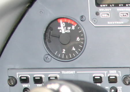
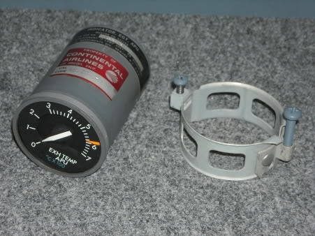
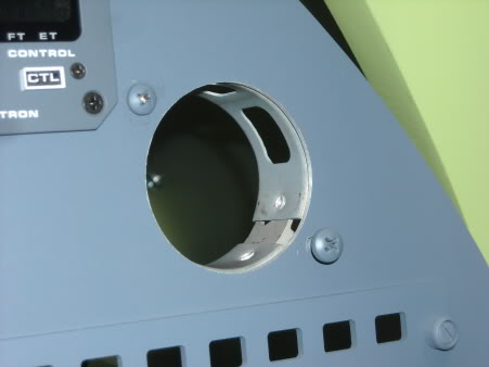
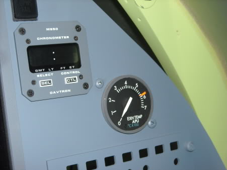
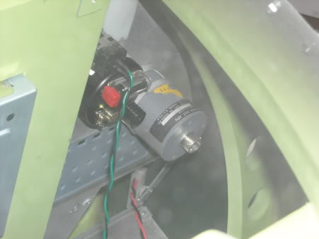
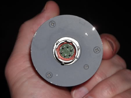
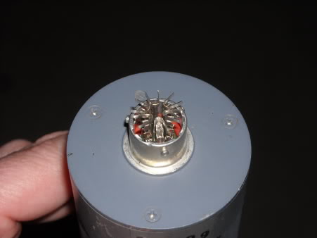
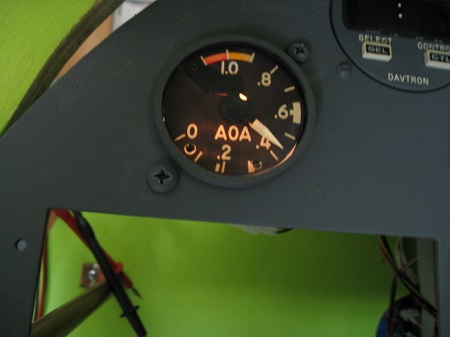
![]()
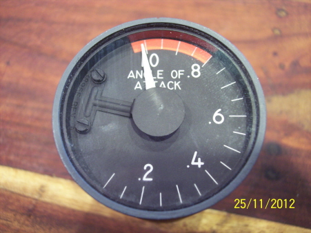
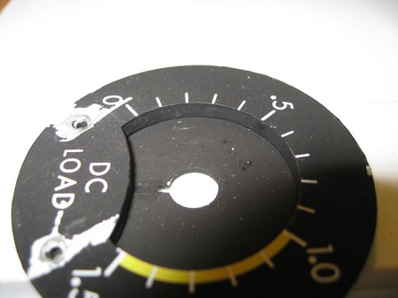
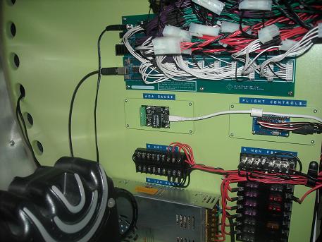
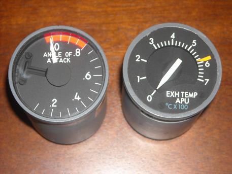
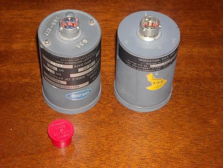
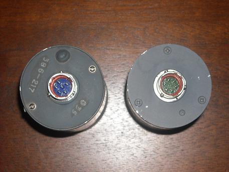
![]()
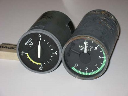
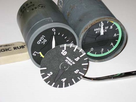
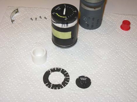
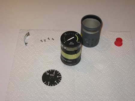
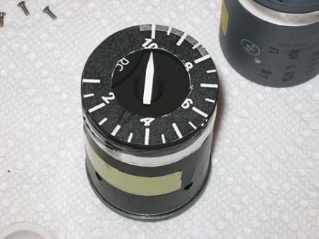
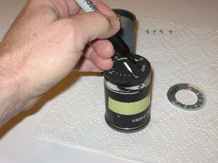
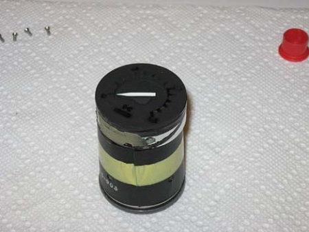
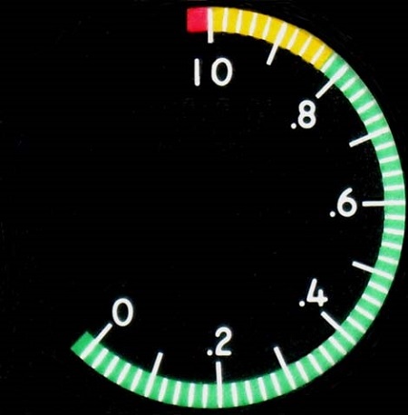
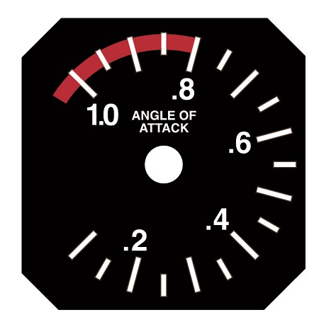
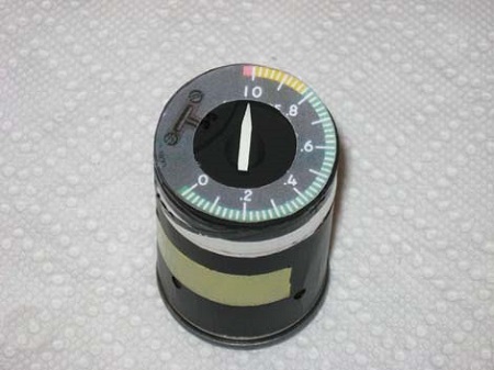
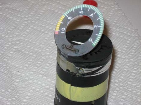
![]()
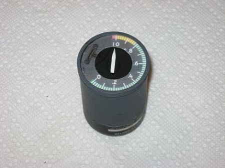
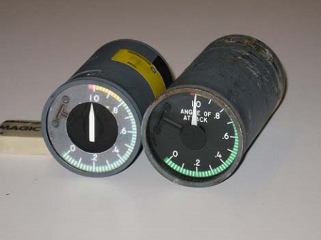
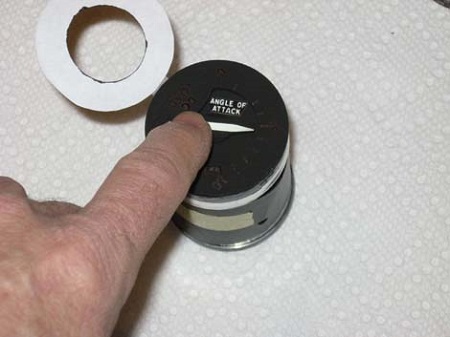
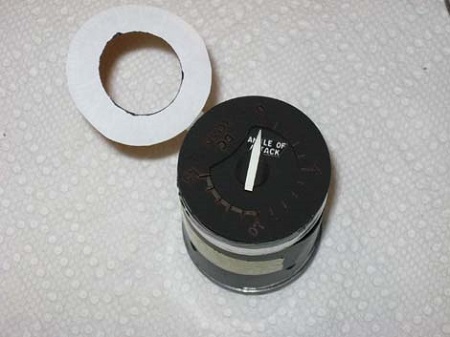

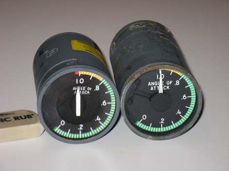
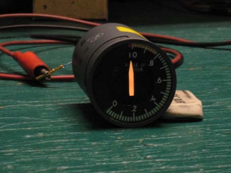
![]()
![]()


![]()


![]()


2017-10-10