


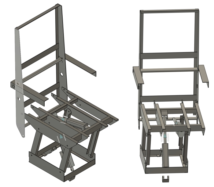
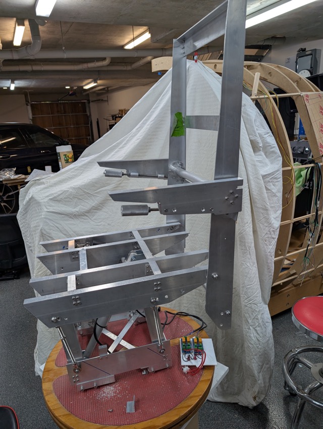
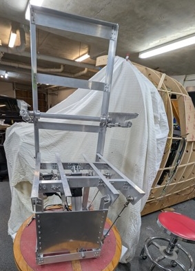
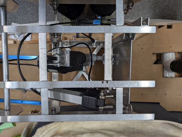
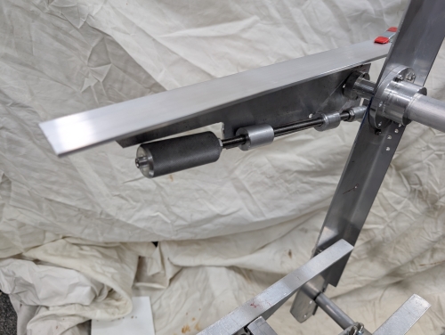
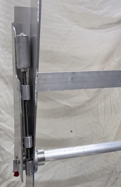
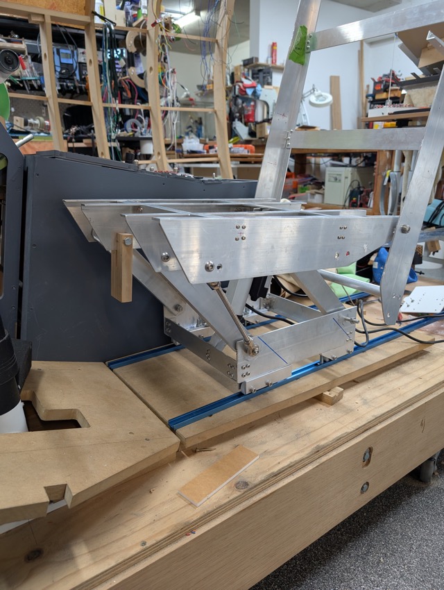
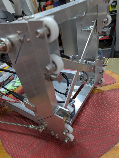
Hi Folks, I have been watching and waiting for a pair of used pilot seats that would fit our sims for a while now, with no success. The idea of spending thousands of dollars + freight for seats that may not fit didn’t thrill me. I decided to have a go at building them myself. Reviewing Rons earlier posts, seeing his progress with his version, asking a few questions and I realised I didn’t want to build in plastic. I was much happier to build in aluminium. Ron had already created a 2D CAD file for the main components of a seat, so all I had to do was come up with the 3rd dimensions and all mechanisms. From Rons 2D drawings and some photos (also from Ron), I drew up this 3D version which is a little bit more utilitarian in shape of components. I didn’t want to do any fancy scroll cutting of aluminium, so its straight lines and right angle corners for most parts. This is purely a design guide with no detail, I would work that out as I built. Which led to this It has the offset base and can be assembled with the overhang to left or right, to suit left or right cockpit seats. I chose to power the seat raise/lower, as well as the seat back angle. This was easier (to me) than fitting a manual rotating shaft and handle. I used two linear actuators - the seat raise/lower is a 3000N (300kg) 10mm/s 100mm actuator, and the seat back is a 3000N (300Kg) 5mm/s 100mm unit. Both are activated by switches under the front of the seat. Each actuators extend/retract is controlled by an SPST toggle (MOM-OFF-MOM), through one of my Polarity Changers which handles switching the reversal of the current, to the actuator . Vertical movement is currently about 55mm. I will attempt to increase this to about 65mm with a bit of actuator position tweaking. The armrests pivot on a pin that is fixed to the armrest and slides in a tube across the backrest, held in position by a custom flange at each end. They can be rotated to vertical and stowed. They are adjustable for height by rotating around the pin. The adjuster is an M8 threaded rod with a free floating knob on one end and push block on the other, and two fixed guide blocks. One guide block is threaded M8., the other is drilled clear 8mm. the push block presses against a tab on the seatback below the armrest pin. Pilot spins the knob which moves the push block in or out which changes the resting angle of the armrest. The seat rolls on nylon tread ball bearings which fit into a woodworkers bench type ‘T’ track. I use one of the T track accessories to prevent lifting out of the track. I made custom spring loaded pin and guide bushes for fore/aft movement lock. These pins fit into 5mm holes I drilled in the T Track. These holes are drilled at 1” spacing for the first 18”. The pins are retracted for seat fore/aft adjustment using pull cables to a lever just under the seat. That’s where I’m at at the moment. Got a couple minor issues to resolve (ie I had to move two of the leg pivot 8mm bolt holes 3mm to the front, that was interesting!) Soon I will cut some plywood for seat base, armrests, and backrest, to be upholstered. For the all important lumbar support (on those long flights) I will bend the seat back in an ergonomic design, fixed lumbar support, until I can imagineer an adjustable one, if needed. Some specs of this build are: I am very happy with the seat. It feels quite solid, runs cleanly and smoothly in the T track, the motors work nicely (so far), it does have a resemblance to the photos of a real Tal J2, and best of all I have less than $800 invested in it, including freight! Yeeah, okay, it has taken me a month of time, but that was fun!! The next one will cost less and take far less time – I know what I’m doing now. I will be making the co-pilot seat soon. All the same pieces just connected to the other two main fore/aft beams… overhang right… Easy!!! If anyone wants I will make a CAD file available, but it will take me a little while to finish it. It turns out that the seats are not that difficult to replicate! This is just a brief overview of my build. I am happy to provide more details if desired. Enjoy... Hi Folks, I have been watching and waiting for a pair of used pilot seats that would fit our sims for a while now, with no success. The idea of spending thousands of dollars + freight for seats that may not fit didn’t thrill me. I decided to have a go at building them myself. Reviewing Rons earlier posts, seeing his progress with his version, asking a few questions and I realised I didn’t want to build in plastic. I was much happier to build in aluminium. Ron had already created a 2D CAD file for the main components of a seat, so all I had to do was come up with the 3rd dimensions and all mechanisms. From Rons 2D drawings and some photos (also from Ron), I drew up this 3D version which is a little bit more utilitarian in shape of components. I didn’t want to do any fancy scroll cutting of aluminium, so its straight lines and right angle corners for most parts. This is purely a design guide with no detail, I would work that out as I built. Which led to this It has the offset base and can be assembled with the overhang to left or right, to suit left or right cockpit seats. I chose to power the seat raise/lower, as well as the seat back angle. This was easier (to me) than fitting a manual rotating shaft and handle. I used two linear actuators - the seat raise/lower is a 3000N (300kg) 10mm/s 100mm actuator, and the seat back is a 3000N (300Kg) 5mm/s 100mm unit. Both are activated by switches under the front of the seat. Each actuators extend/retract is controlled by an SPST toggle (MOM-OFF-MOM), through one of my Polarity Changers which handles switching the reversal of the current, to the actuator . Vertical movement is currently about 55mm. I will attempt to increase this to about 65mm with a bit of actuator position tweaking. The armrests pivot on a pin that is fixed to the armrest and slides in a tube across the backrest, held in position by a custom flange at each end. They can be rotated to vertical and stowed. They are adjustable for height by rotating around the pin. The adjuster is an M8 threaded rod with a free floating knob on one end and push block on the other, and two fixed guide blocks. One guide block is threaded M8., the other is drilled clear 8mm. the push block presses against a tab on the seatback below the armrest pin. Pilot spins the knob which moves the push block in or out which changes the resting angle of the armrest. The seat rolls on nylon tread ball bearings which fit into a woodworkers bench type ‘T’ track. I use one of the T track accessories to prevent lifting out of the track. I made custom spring loaded pin and guide bushes for fore/aft movement lock. These pins fit into 5mm holes I drilled in the T Track. These holes are drilled at 1” spacing for the first 18”. The pins are retracted for seat fore/aft adjustment using pull cables to a lever just under the seat. That’s where I’m at at the moment. Got a couple minor issues to resolve (ie I had to move two of the leg pivot 8mm bolt holes 3mm to the front, that was interesting!) Soon I will cut some plywood for seat base, armrests, and backrest, to be upholstered. For the all important lumbar support (on those long flights) I will bend the seat back in an ergonomic design, fixed lumbar support, until I can imagineer an adjustable one, if needed. Some specs of this build are: I am very happy with the seat. It feels quite solid, runs cleanly and smoothly in the T track, the motors work nicely (so far), it does have a resemblance to the photos of a real Tal J2, and best of all I have less than $800 invested in it, including freight! Yeeah, okay, it has taken me a month of time, but that was fun!! The next one will cost less and take far less time – I know what I’m doing now. I will be making the co-pilot seat soon. All the same pieces just connected to the other two main fore/aft beams… overhang right… Easy!!! If anyone wants I will make a CAD file available, but it will take me a little while to finish it. It turns out that the seats are not that difficult to replicate! This is just a brief overview of my build. I am happy to provide more details if desired. Enjoy...Replica Seats by Will_S
![]()
2017-10-10