


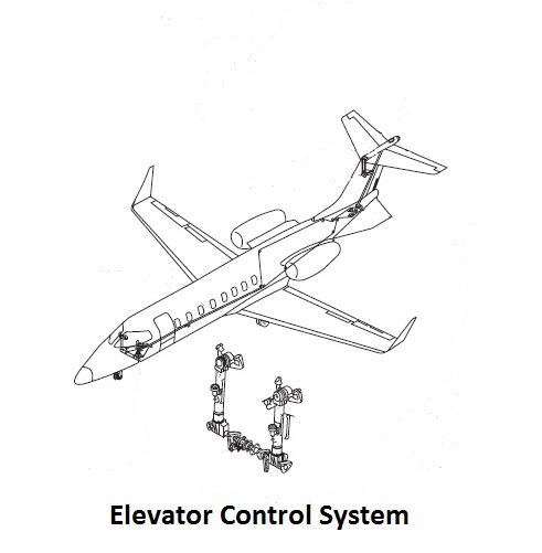
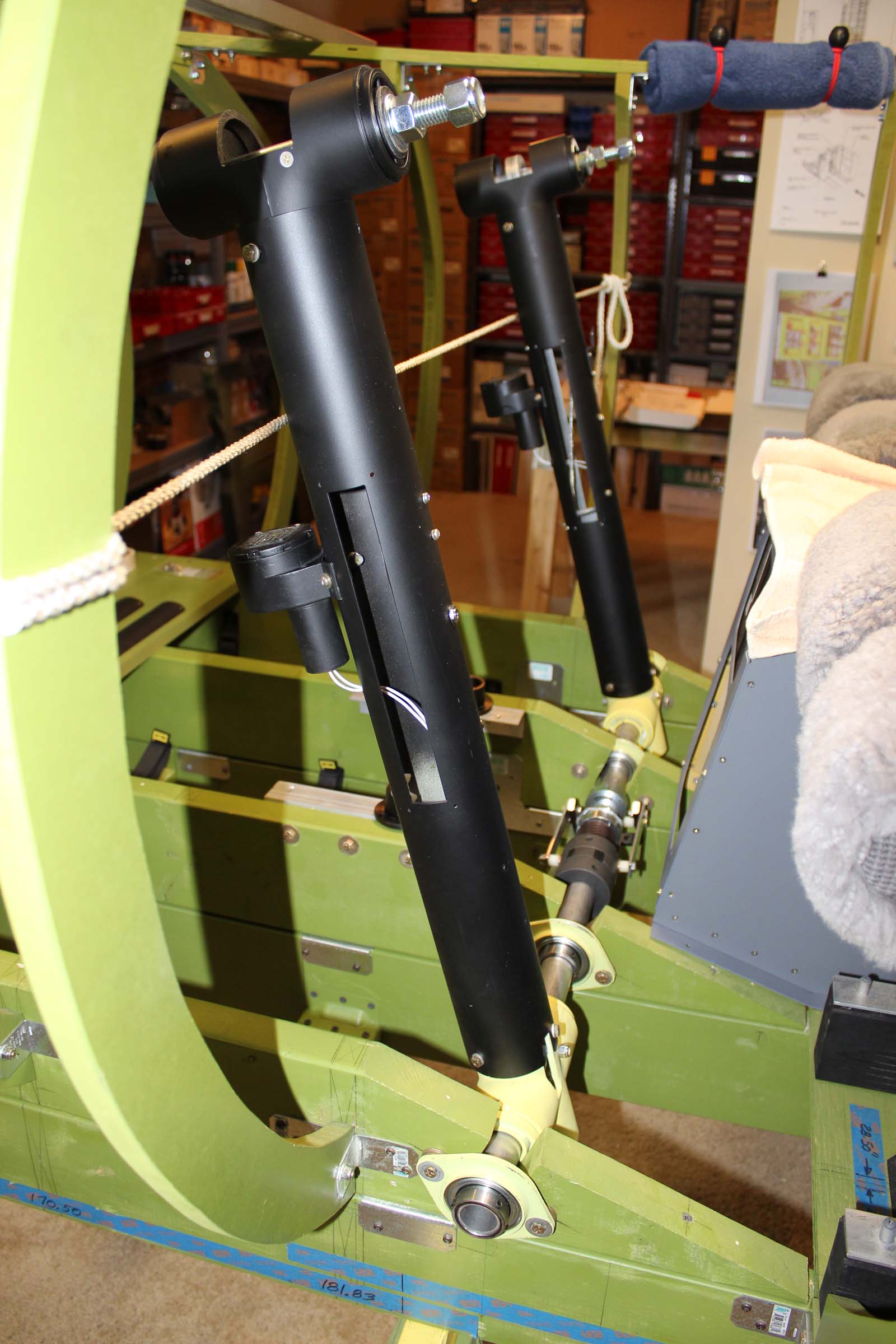
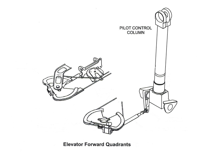
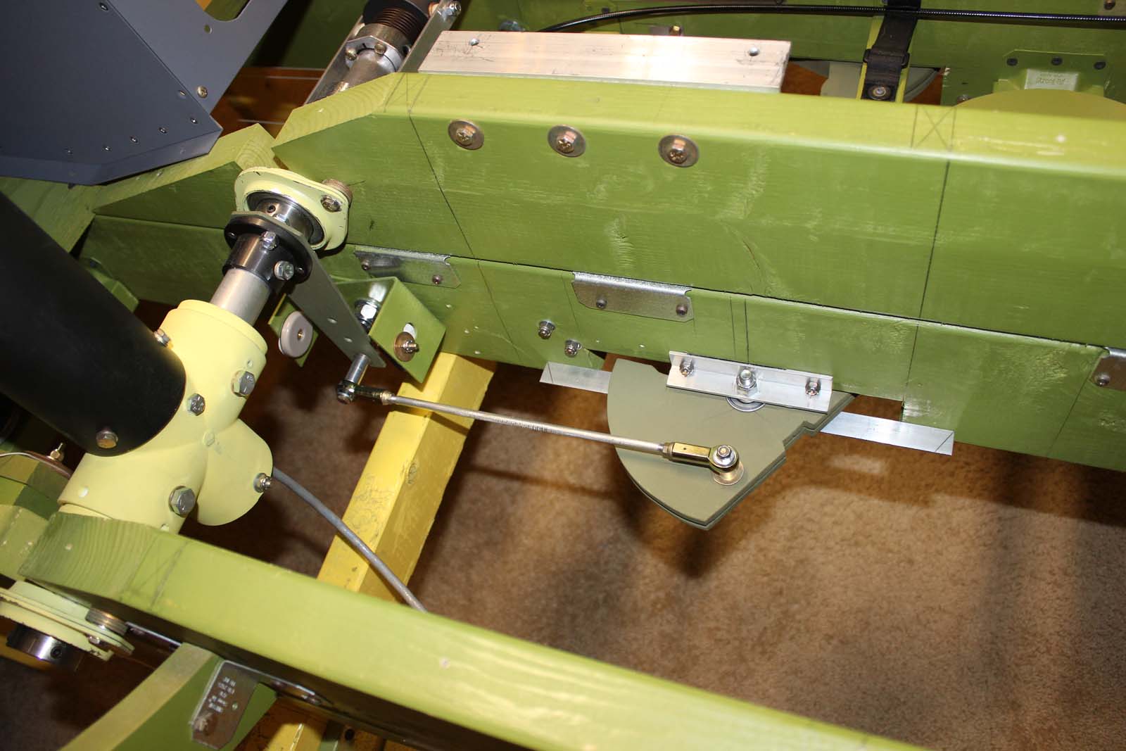
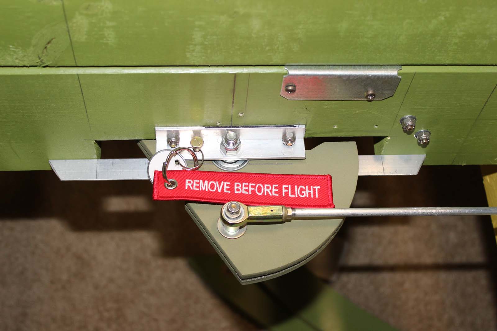
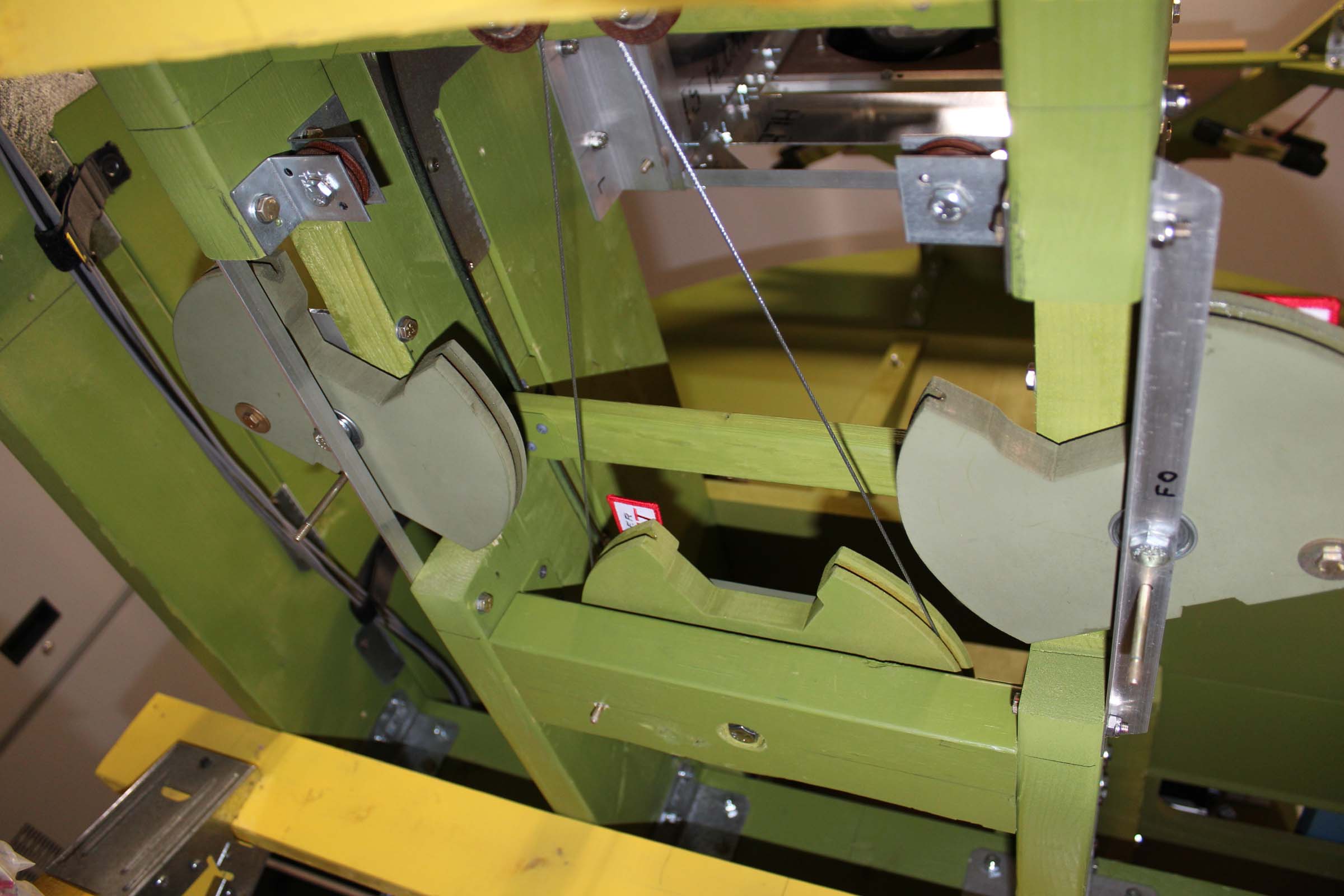
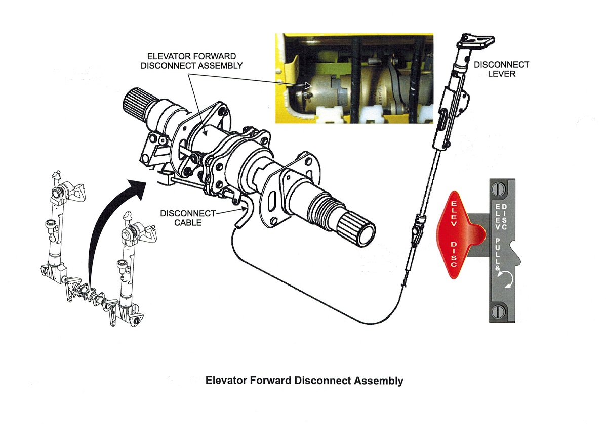
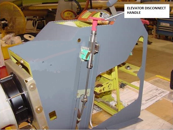
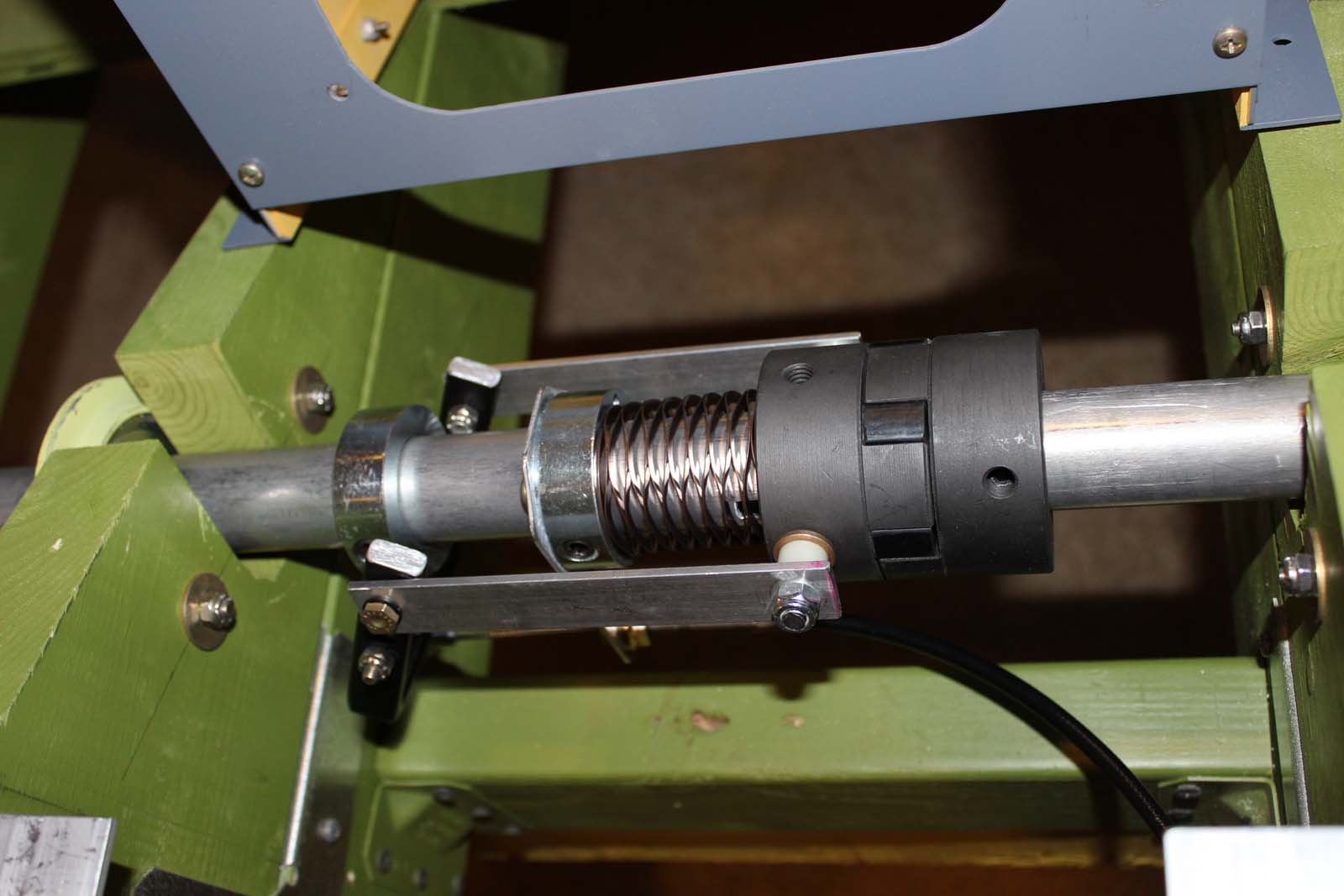
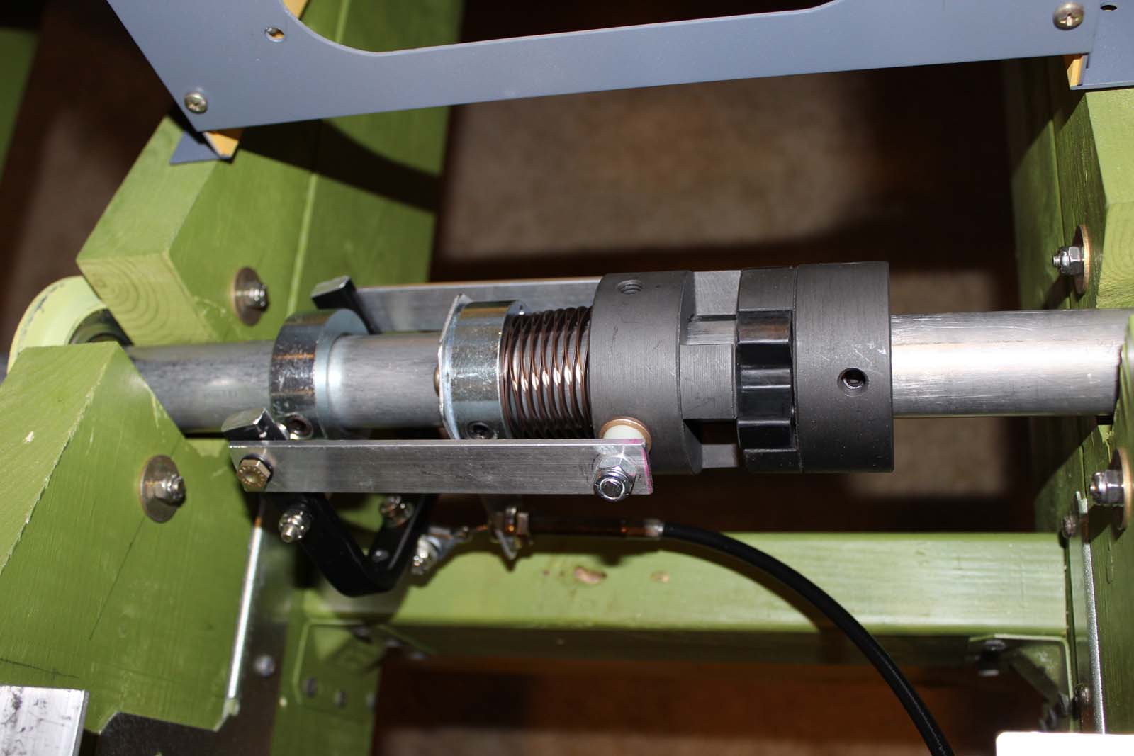
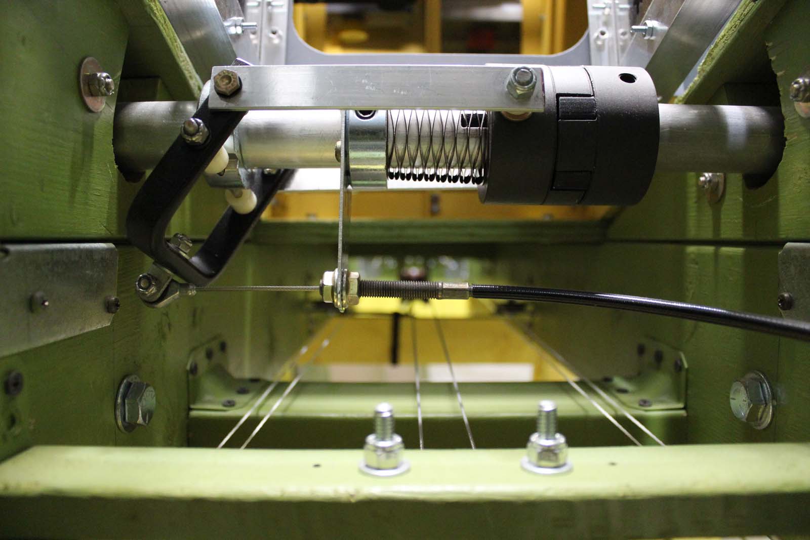
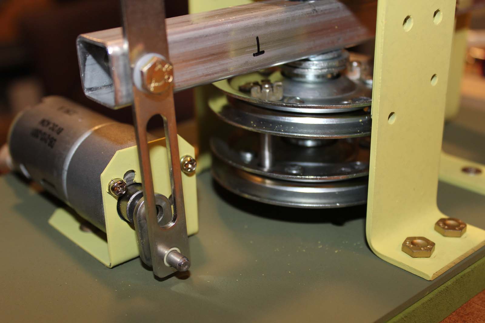
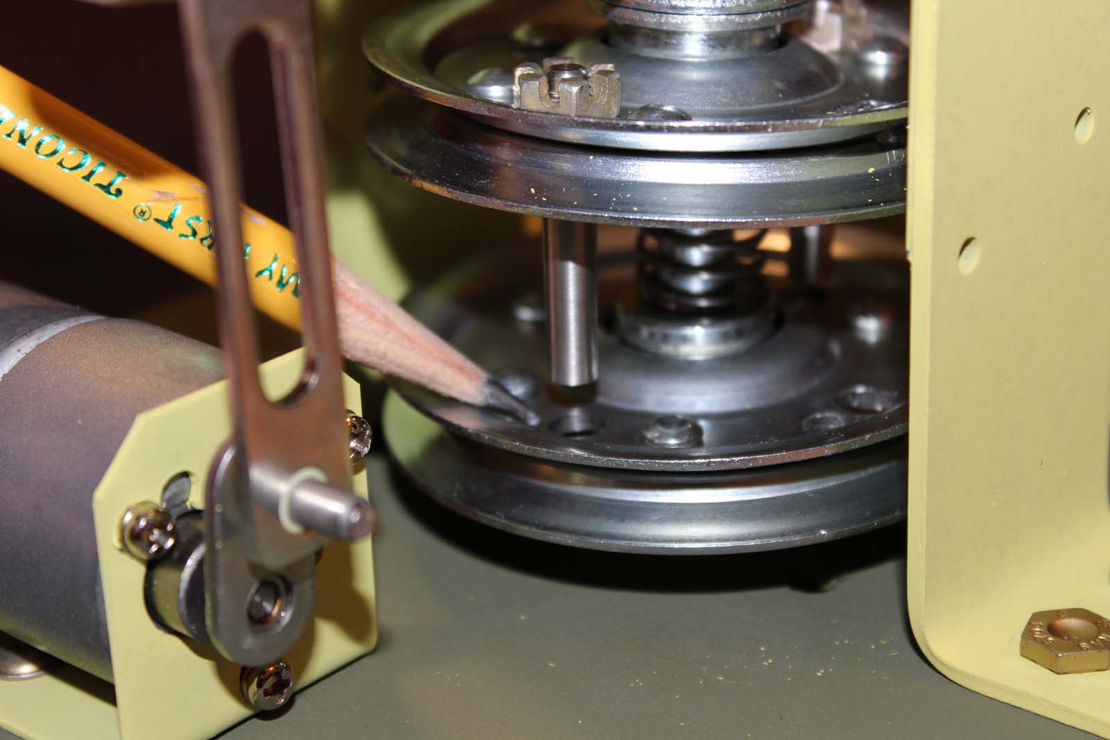
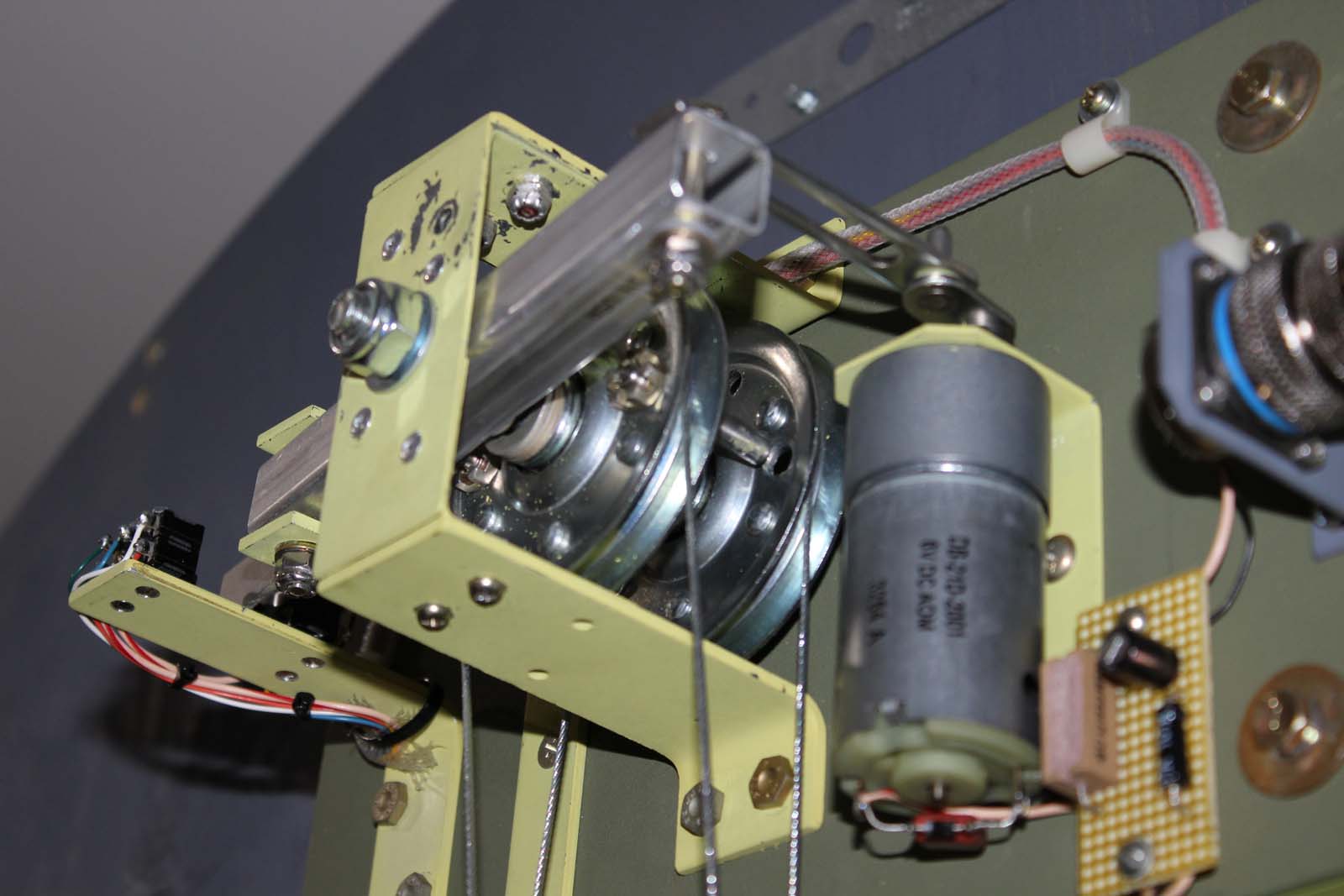
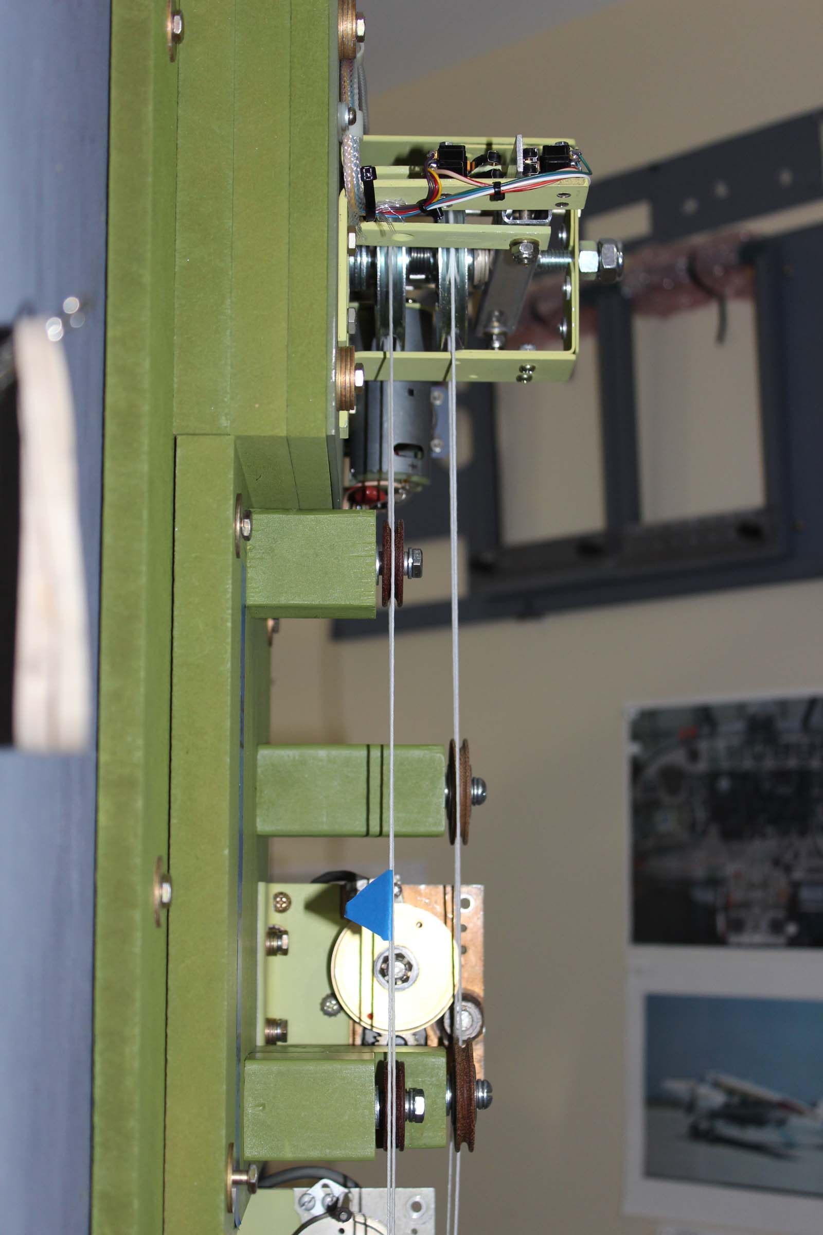
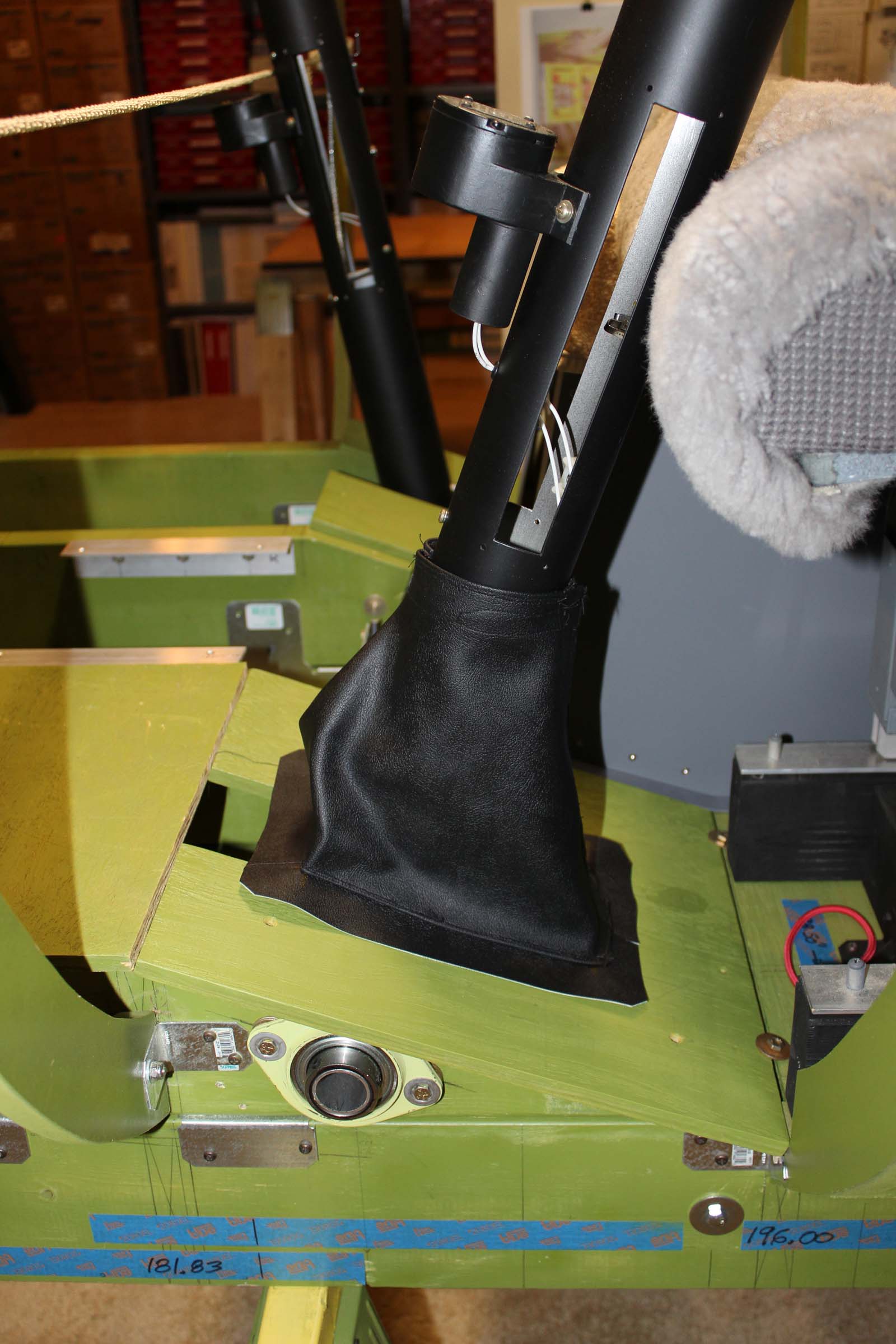
Lear 45-1001 Build History ATA 27-30, Elevators Rev Dec 17 2019 The L45-1001 introduction contains useful background information on this build. If somehow you have arrived at this place and have not read the L45-1001 introduction you will find it HERE: Elevators: Yes-there are TWO. The Learjet 45 has two independently controllable elevator systems. Two independent systems provide a means of maintaining pitch control in the event of an elevator jam, system fault, or physical damage to the elevator surfaces themselves. Because there are two independent elevator surfaces there must also be two independent elevator control systems. In simple terms, this means that there are separate elevator control cables between the pilot and left elevator surface, and the copilot and right elevator surface. These control cables are physically separated as they pass through the rotor burst zone near the engines. Should an uncontained engine failure damage one set of control cables it is unlikely the other set would also be damaged. The remaining functional set may be used to maintain pitch control. The elevators are controlled by moving the cockpit control columns forward or aft to the desired position. Moving the control columns operates a linkage which turns a forward elevator quadrant. There are two quadrants, one on the left and one on the right. Under normal conditions the control columns are locked together and move as a single mechanism. Control cables run from each elevator quadrant back to the tailcone area where they operate a system of linkages that physically move the elevator surfaces. L45-1001 contains a simplified version of the elevator control system. Each control column moves an on-side quadrant. Control cables from each quadrant travel aft and terminate at the aft elevator disconnect clutch. The photo below is the right side control column, linkage, and quadrant. The left side is a mirror image of it. In aircraft control systems it is often necessary to align the various moving parts that drive some control surface. This is made easier by the use of “rigging pins” which are inserted in designated locations. The rigging pins lock the various moving parts into a known calibrated position. This makes it MUCH easier to properly rig the system and adjust cable tensions. Here is the pilot side elevator quadrant with the rigging pin installed. (My rigging pins are made from an AN3 bolt attached to a Learjet key ring. They’re not fancy, but they are inexpensive to make and they work.) Here is a view of both elevator quadrants. This photo was taken by lying on the floor under the airframe and trying to hold the camera to get a decent image. In the photo the top of the picture is “aft”. The sharp-eyed among you will notice the rigging pins inserted in both quadrants. Elevator control cables are not yet installed. The larger quadrant in the center is the rudder quadrant. The rudder control system is described in ATA-27-20 (and has not been posted as of this writing.) The elevator disconnect system works like this: A forward elevator disconnect assembly provides a means to mechanically isolate the left side control column from the right side control column. This assembly contains a clutch which is operated by a red control handle on the left side of the forward pedestal. The handle is labeled “Elev Disc”. When desired, pulling the red handle and locking it in place operates the disconnect assembly installed on the torque (crossover) tube. The result is two completely isolated control column systems, each with a torque tube, linkage, quadrant, and control cable circuit. After pulling the red disconnect handle, the crew can determine which elevator remains functional and can use that side to retain pitch control. This photo shows the location of the elevator disconnect handle in the cockpit. It’s not the handle in L45-1001 because I don’t have a handle yet. (HINT, HINT, Mr. Barnes.) Here are photos of the forward elevator disconnect clutch in L45-1001. It is a simplified version of the assembly found in the real aircraft. It is made from common parts and materials and can be replicated by any builder with average skills and modest tools. Here is the clutch in the “engaged” position. Both control columns move together in the engaged position. Here is the clutch in the “disconnected” position. Each control column is isolated from the other and moves independently. It is not viewable in this photo, but the torque tubes (left and right) are separated exactly between the two halves of the coupling. Another view of the forward elevator disconnect clutch. This photo was taken under the floor looking “aft”. The camera was sitting on top of the rudder quadrant. The forward disconnect clutch isolates the control columns but in order for the elevator disconnect *system* to work another disconnect clutch is required back in the aft area of the aircraft. The aft elevator disconnect clutch isolates the linkages that connect directly to and move the elevator surfaces on the tail. The “elevator”, as we commonly think of it, on the Learjet 45 is actually split in half. The left half is controlled via the left control system, and the right half is controlled via the right control system. Normally the left and right systems are locked together and thus the entire elevator moves as a single control surface. But when the Elev Disc handle is pulled, the two systems are isolated from each other and each half of the elevator moves independent of the other. In the real aircraft the tailcone contains several assemblies that control the elevators using a combination of cables, hinges, and linkages. The elevator surfaces themselves are moved by linkages, which are in turn commanded by the control cables coming from the front of the aircraft. It is a complex system with many special parts. We’re not building those parts. We don’t have physical elevators in our sims. But L45-1001 does have a functional autopilot including servos that are in the control cable circuit. The aft disconnect clutch in L45-1001 is necessarily of a different design than that of the real aircraft. In L45-1001 we need to isolate cables but in the real aircraft it is necessary to isolate linkages. Someone will ask, “Why go to the effort to replicate the elevator disconnect system since we don’t have physical elevators?” Answer: Fly like you train – train like you fly. We don’t have physical engines either but no one would suggest leaving out the throttle handles! Here is the aft elevator disconnect clutch installed in L45-1001. It consists basically of two pulleys which can be locked together or isolated remotely via a small gear motor. The gear motor is controlled by switches located on the Elev Disc handle in the cockpit. When the handle is in the normal position a pin engages a hole in one pulley and locks it to the other pulley. In this photo, the locking pin is seen just below the inverted letter “T” written on the actuator arm. This is the “engaged” or locked position. Here is the clutch in the “disconnected” position. The upper pulley has moved away from the lower pulley and disengaged the locking pin. In this position each pulley is free to move independently of the other. The combination of the forward disconnect clutch and the aft disconnect clutch provides the means to isolate each elevator control circuit from the other. The forward clutch is manually operated by pulling the Elev Disc handle. Switches on that handle electrically command the aft clutch to follow to the desired position. The aft elevator disconnect clutch is mounted near the top of the aft bulkhead above the autopilot servos and sensors. It is easier to maintain cable alignment if the control cables pass through the servos and sensors first and then continue up to the disconnect clutch. Here is the clutch with the elevator control cables installed and ready for use. It is “disconnected” in this photo. Here is a side view of the aft elevator disconnect clutch assembly showing how the control cables are rigged to it. Both cables are essentially parallel and are separated by the distance between the pulleys. The clutch is engaged (locked) in this photo. In the disconnected position the pulley and cable on the right moves to the right (aft) about 0.5 inches. This is sufficient to allow the locking pin to clear the pulley on the left. The system works quite well. It will work even better when Mr. Barnes makes that Elev Disc handle for me! Heh…heh…heh….. HOME: This link goes to the L45-1001 build history introduction. Links to other L45-1001 posts are found at the END of the introduction. Lear 45-1001 Build History ATA 27-30, Elevators Rev Dec 17 2019 The L45-1001 introduction contains useful background information on this build. If somehow you have arrived at this place and have not read the L45-1001 introduction you will find it HERE: Elevators: Yes-there are TWO. The Learjet 45 has two independently controllable elevator systems. Two independent systems provide a means of maintaining pitch control in the event of an elevator jam, system fault, or physical damage to the elevator surfaces themselves. Because there are two independent elevator surfaces there must also be two independent elevator control systems. In simple terms, this means that there are separate elevator control cables between the pilot and left elevator surface, and the copilot and right elevator surface. These control cables are physically separated as they pass through the rotor burst zone near the engines. Should an uncontained engine failure damage one set of control cables it is unlikely the other set would also be damaged. The remaining functional set may be used to maintain pitch control. The elevators are controlled by moving the cockpit control columns forward or aft to the desired position. Moving the control columns operates a linkage which turns a forward elevator quadrant. There are two quadrants, one on the left and one on the right. Under normal conditions the control columns are locked together and move as a single mechanism. Control cables run from each elevator quadrant back to the tailcone area where they operate a system of linkages that physically move the elevator surfaces. L45-1001 contains a simplified version of the elevator control system. Each control column moves an on-side quadrant. Control cables from each quadrant travel aft and terminate at the aft elevator disconnect clutch. The photo below is the right side control column, linkage, and quadrant. The left side is a mirror image of it. In aircraft control systems it is often necessary to align the various moving parts that drive some control surface. This is made easier by the use of “rigging pins” which are inserted in designated locations. The rigging pins lock the various moving parts into a known calibrated position. This makes it MUCH easier to properly rig the system and adjust cable tensions. Here is the pilot side elevator quadrant with the rigging pin installed. (My rigging pins are made from an AN3 bolt attached to a Learjet key ring. They’re not fancy, but they are inexpensive to make and they work.) Here is a view of both elevator quadrants. This photo was taken by lying on the floor under the airframe and trying to hold the camera to get a decent image. In the photo the top of the picture is “aft”. The sharp-eyed among you will notice the rigging pins inserted in both quadrants. Elevator control cables are not yet installed. The larger quadrant in the center is the rudder quadrant. The rudder control system is described in ATA-27-20 (and has not been posted as of this writing.) The elevator disconnect system works like this: A forward elevator disconnect assembly provides a means to mechanically isolate the left side control column from the right side control column. This assembly contains a clutch which is operated by a red control handle on the left side of the forward pedestal. The handle is labeled “Elev Disc”. When desired, pulling the red handle and locking it in place operates the disconnect assembly installed on the torque (crossover) tube. The result is two completely isolated control column systems, each with a torque tube, linkage, quadrant, and control cable circuit. After pulling the red disconnect handle, the crew can determine which elevator remains functional and can use that side to retain pitch control. This photo shows the location of the elevator disconnect handle in the cockpit. It’s not the handle in L45-1001 because I don’t have a handle yet. (HINT, HINT, Mr. Barnes.) Here are photos of the forward elevator disconnect clutch in L45-1001. It is a simplified version of the assembly found in the real aircraft. It is made from common parts and materials and can be replicated by any builder with average skills and modest tools. Here is the clutch in the “engaged” position. Both control columns move together in the engaged position. Here is the clutch in the “disconnected” position. Each control column is isolated from the other and moves independently. It is not viewable in this photo, but the torque tubes (left and right) are separated exactly between the two halves of the coupling. Another view of the forward elevator disconnect clutch. This photo was taken under the floor looking “aft”. The camera was sitting on top of the rudder quadrant. The forward disconnect clutch isolates the control columns but in order for the elevator disconnect *system* to work another disconnect clutch is required back in the aft area of the aircraft. The aft elevator disconnect clutch isolates the linkages that connect directly to and move the elevator surfaces on the tail. The “elevator”, as we commonly think of it, on the Learjet 45 is actually split in half. The left half is controlled via the left control system, and the right half is controlled via the right control system. Normally the left and right systems are locked together and thus the entire elevator moves as a single control surface. But when the Elev Disc handle is pulled, the two systems are isolated from each other and each half of the elevator moves independent of the other. In the real aircraft the tailcone contains several assemblies that control the elevators using a combination of cables, hinges, and linkages. The elevator surfaces themselves are moved by linkages, which are in turn commanded by the control cables coming from the front of the aircraft. It is a complex system with many special parts. We’re not building those parts. We don’t have physical elevators in our sims. But L45-1001 does have a functional autopilot including servos that are in the control cable circuit. The aft disconnect clutch in L45-1001 is necessarily of a different design than that of the real aircraft. In L45-1001 we need to isolate cables but in the real aircraft it is necessary to isolate linkages. Someone will ask, “Why go to the effort to replicate the elevator disconnect system since we don’t have physical elevators?” Answer: Fly like you train – train like you fly. We don’t have physical engines either but no one would suggest leaving out the throttle handles! Here is the aft elevator disconnect clutch installed in L45-1001. It consists basically of two pulleys which can be locked together or isolated remotely via a small gear motor. The gear motor is controlled by switches located on the Elev Disc handle in the cockpit. When the handle is in the normal position a pin engages a hole in one pulley and locks it to the other pulley. In this photo, the locking pin is seen just below the inverted letter “T” written on the actuator arm. This is the “engaged” or locked position. Here is the clutch in the “disconnected” position. The upper pulley has moved away from the lower pulley and disengaged the locking pin. In this position each pulley is free to move independently of the other. The combination of the forward disconnect clutch and the aft disconnect clutch provides the means to isolate each elevator control circuit from the other. The forward clutch is manually operated by pulling the Elev Disc handle. Switches on that handle electrically command the aft clutch to follow to the desired position. The aft elevator disconnect clutch is mounted near the top of the aft bulkhead above the autopilot servos and sensors. It is easier to maintain cable alignment if the control cables pass through the servos and sensors first and then continue up to the disconnect clutch. Here is the clutch with the elevator control cables installed and ready for use. It is “disconnected” in this photo. Here is a side view of the aft elevator disconnect clutch assembly showing how the control cables are rigged to it. Both cables are essentially parallel and are separated by the distance between the pulleys. The clutch is engaged (locked) in this photo. In the disconnected position the pulley and cable on the right moves to the right (aft) about 0.5 inches. This is sufficient to allow the locking pin to clear the pulley on the left. The system works quite well. It will work even better when Mr. Barnes makes that Elev Disc handle for me! Heh…heh…heh….. HOME: This link goes to the L45-1001 build history introduction. Links to other L45-1001 posts are found at the END of the introduction.L45-1001, ATA 27-30 Elevators
![]()
2017-10-10