


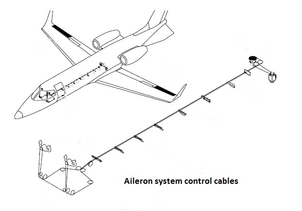
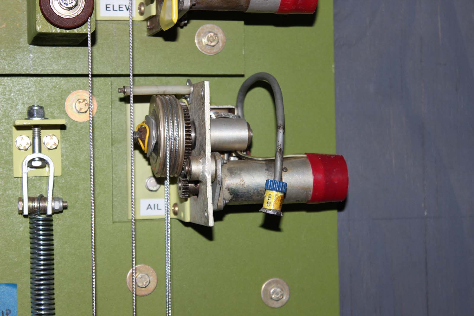
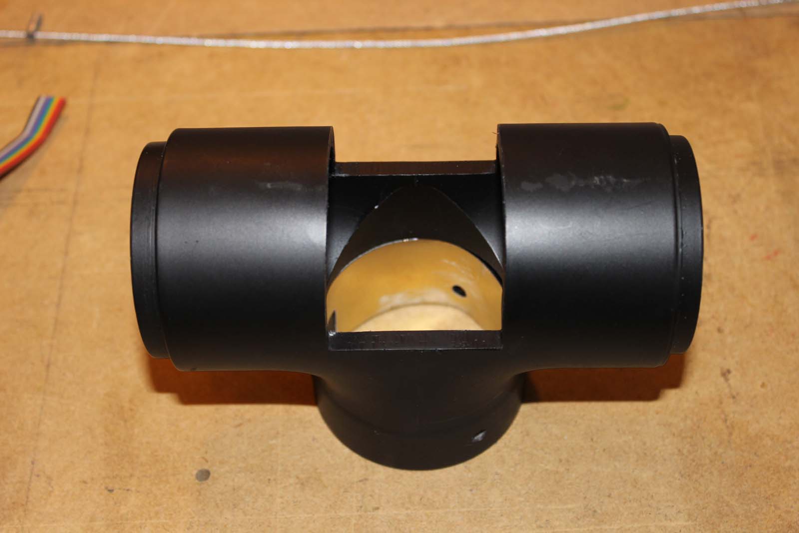
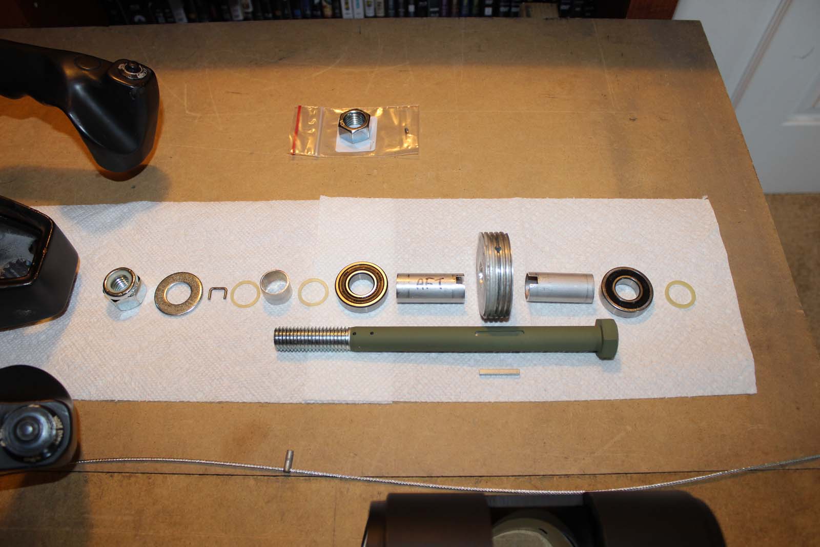
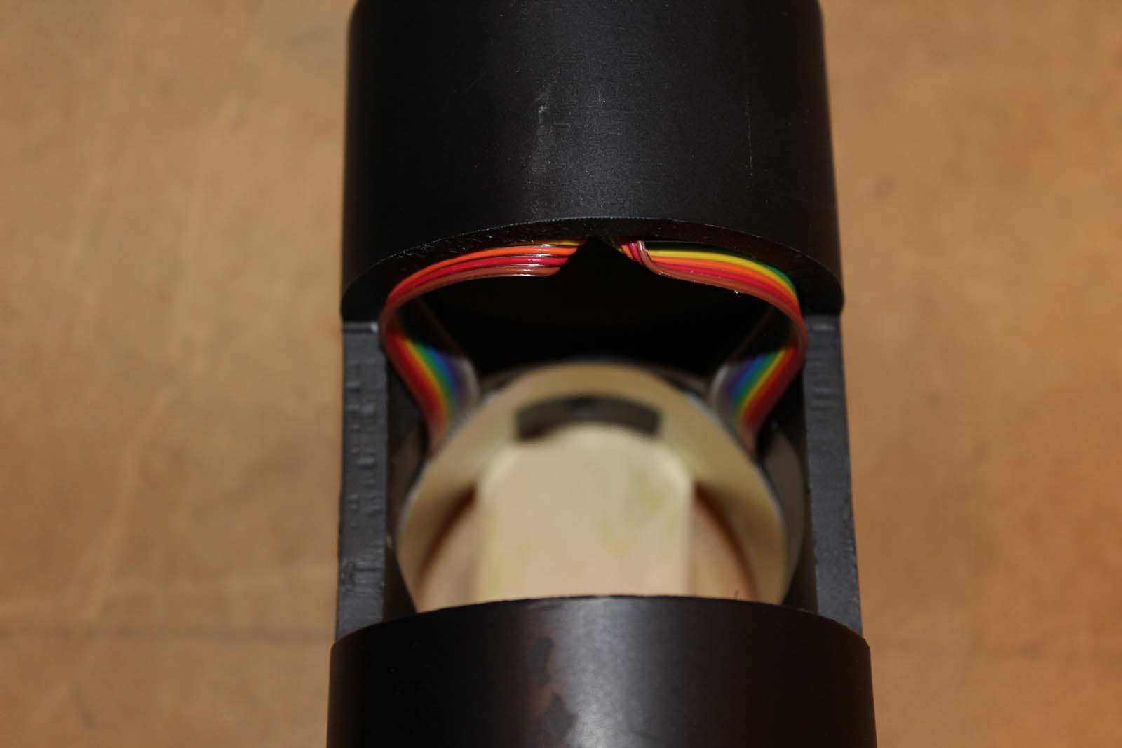
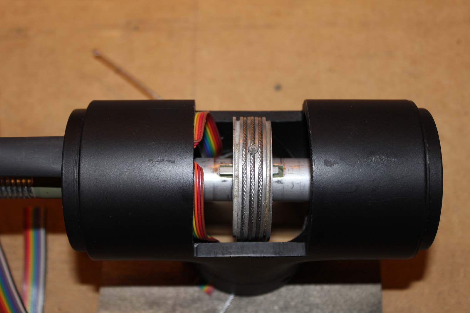
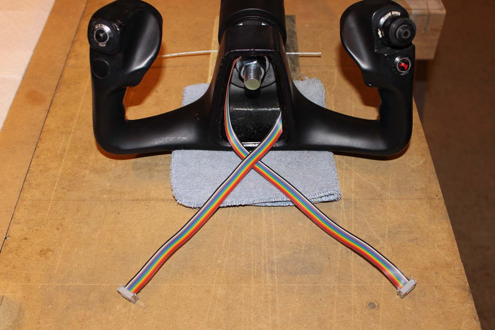
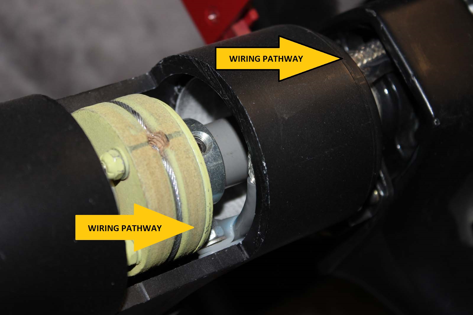
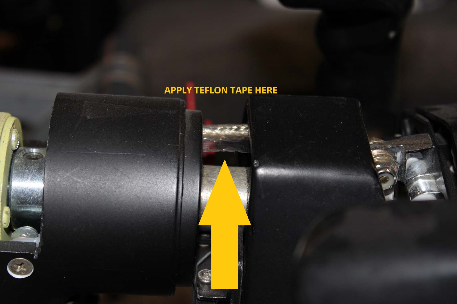
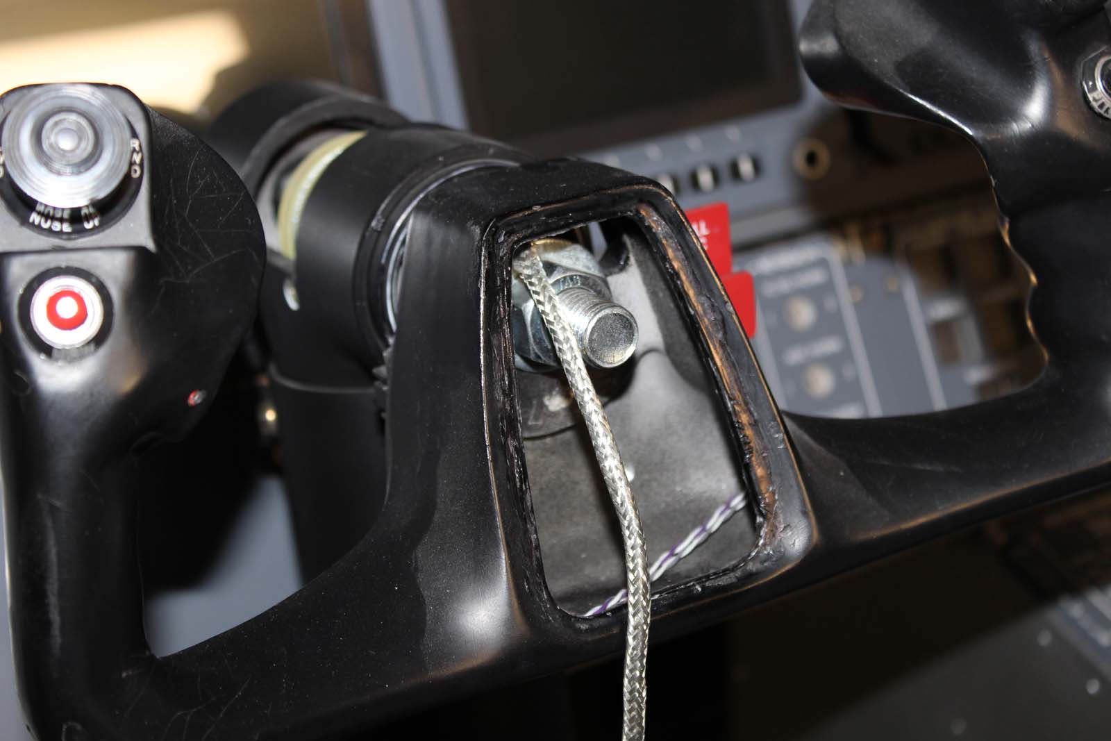
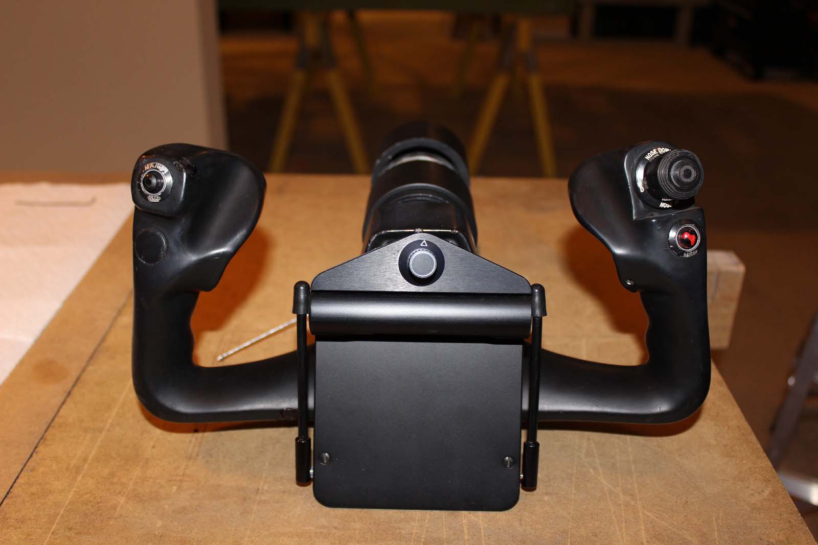
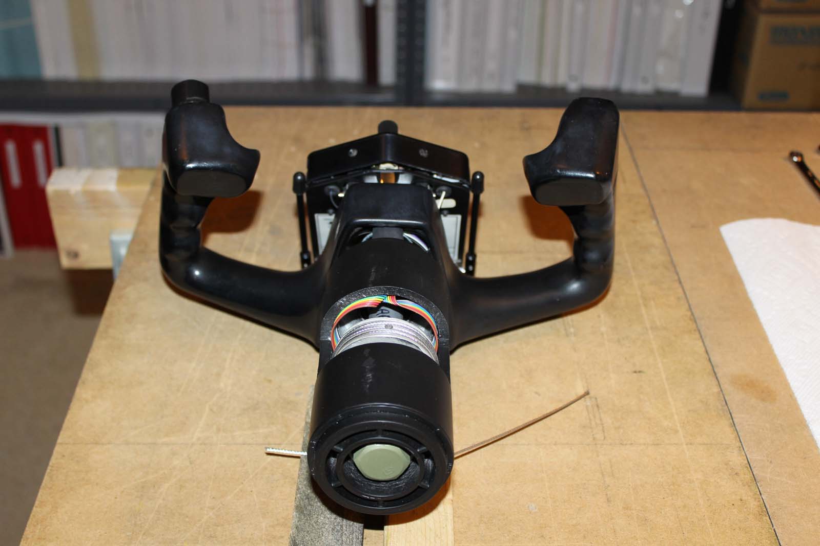
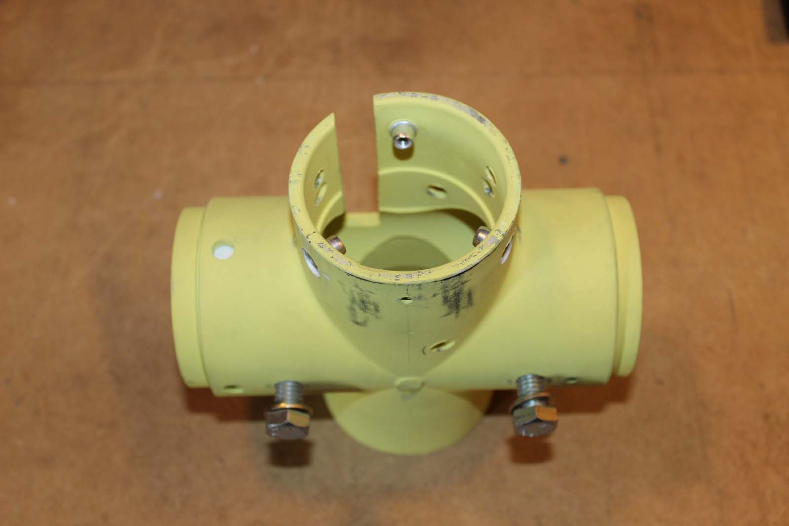
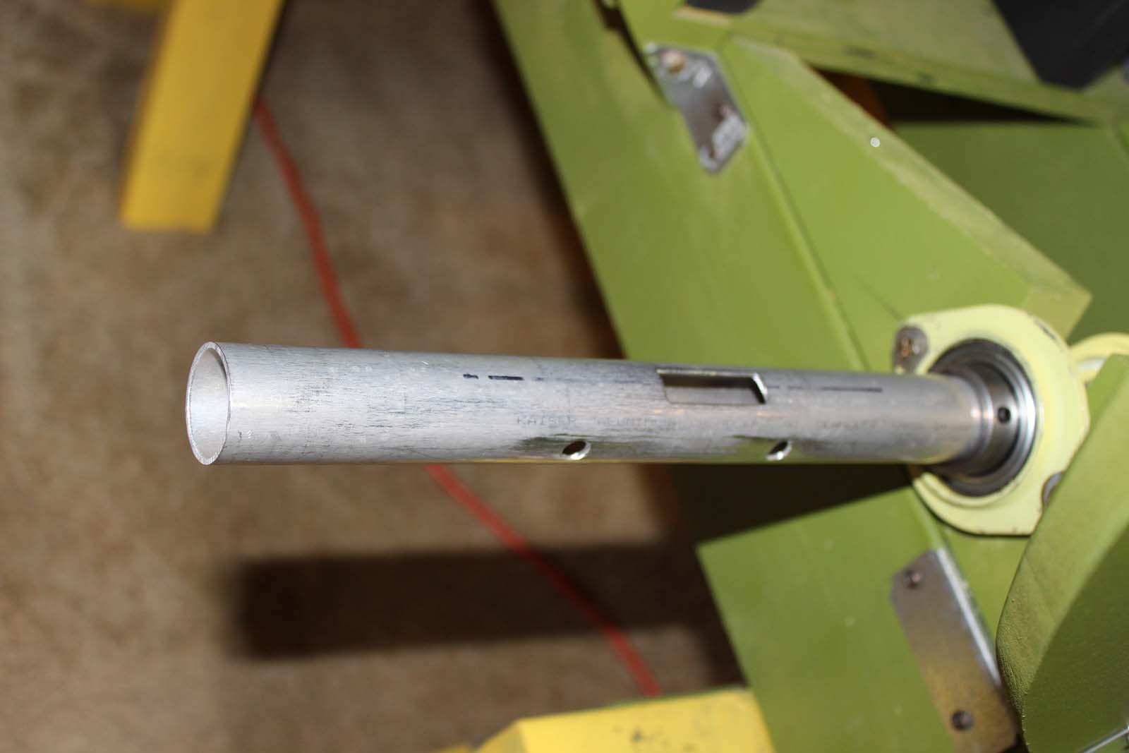
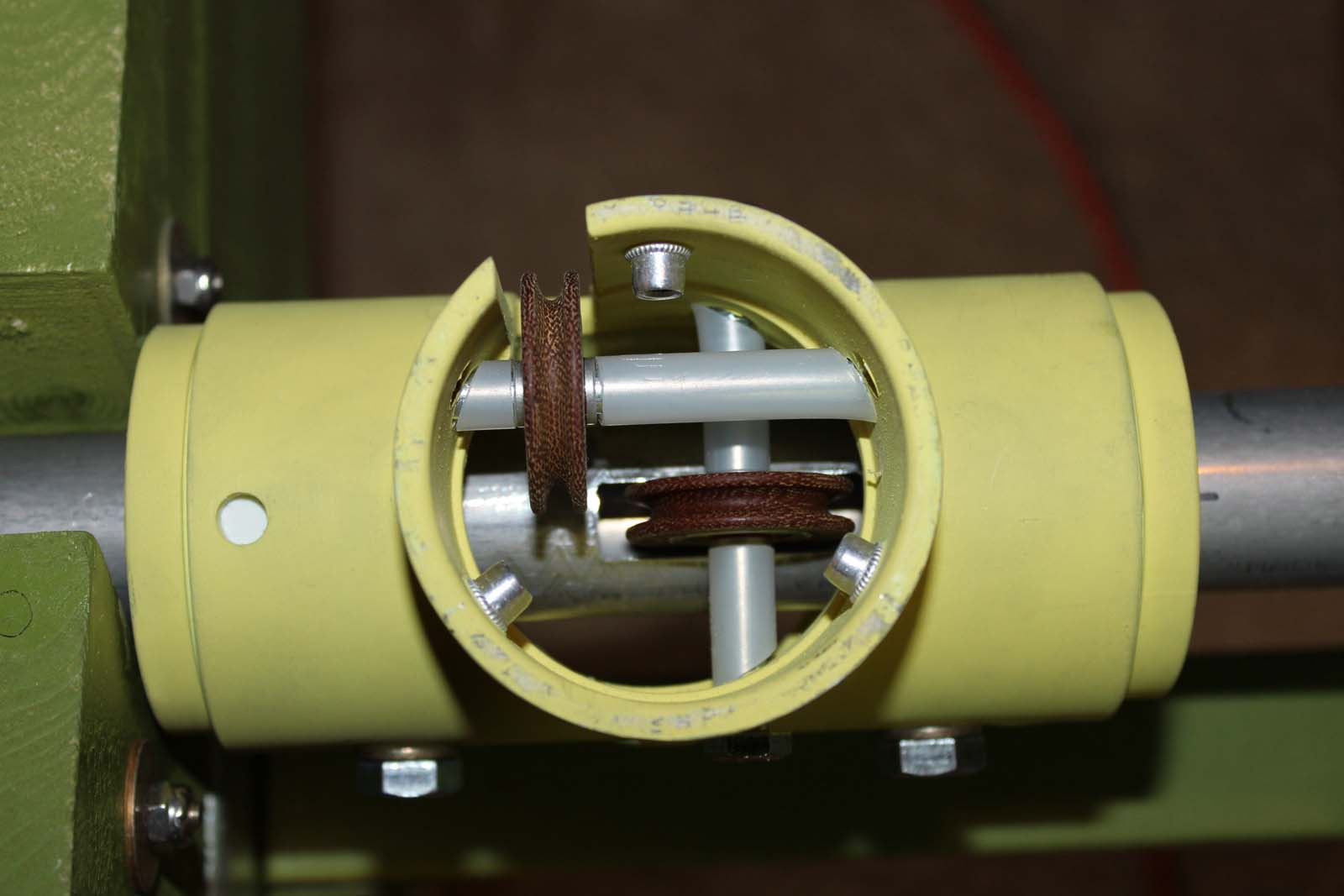
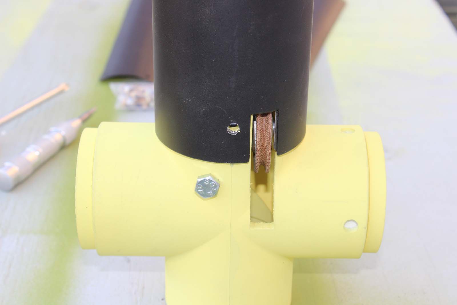
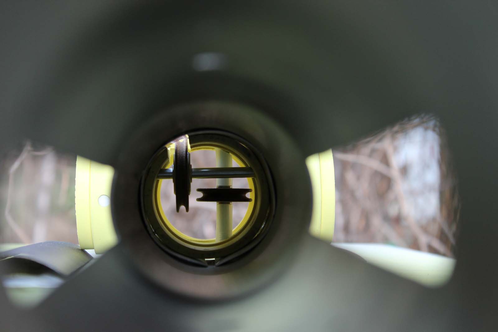
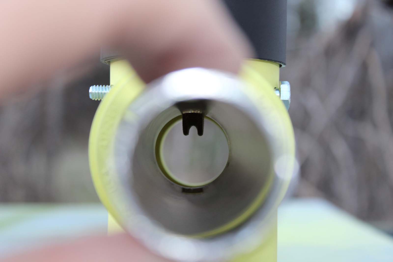
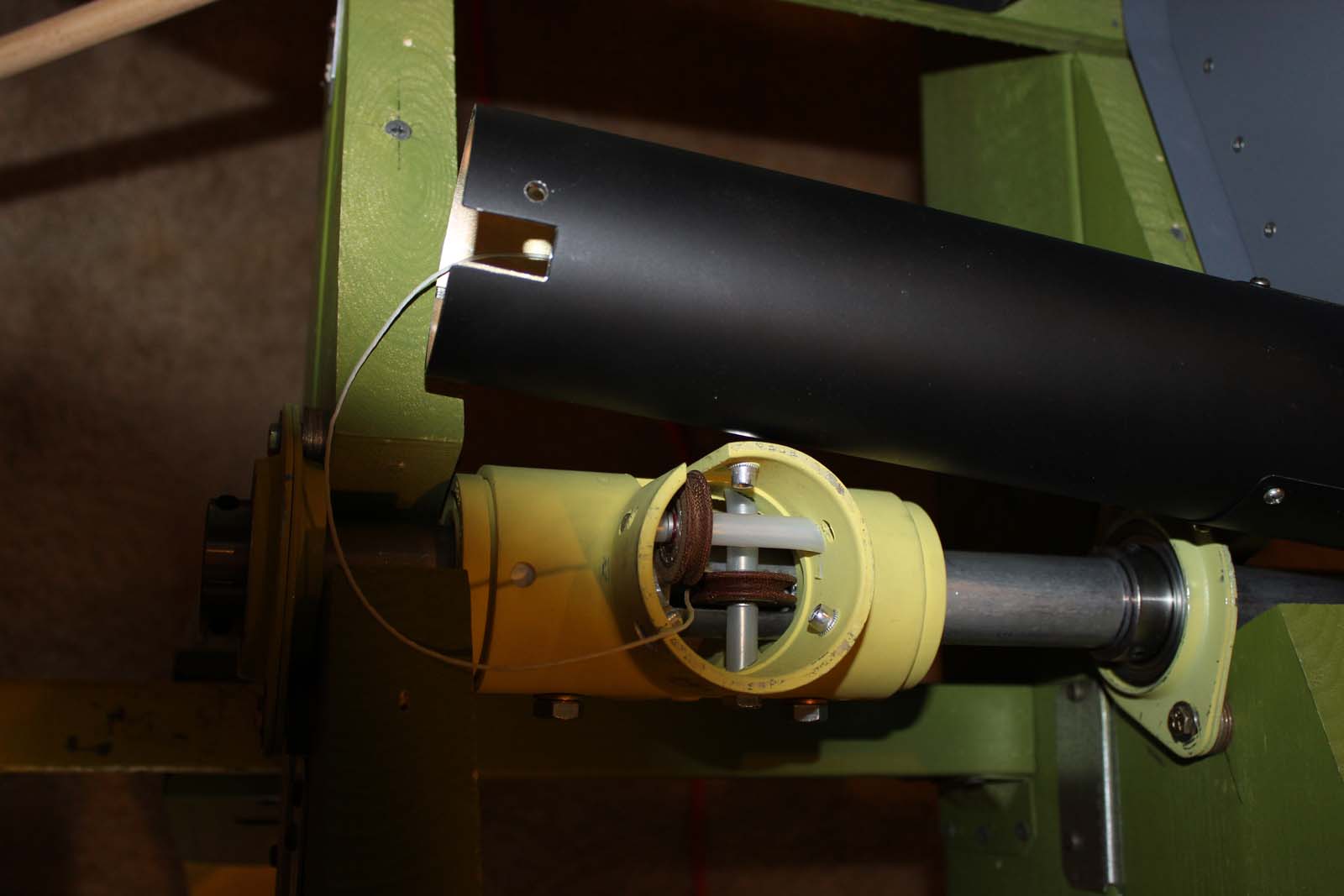
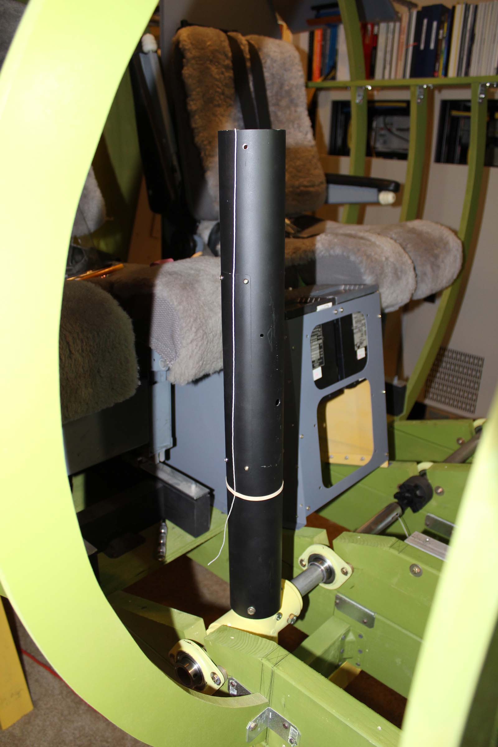
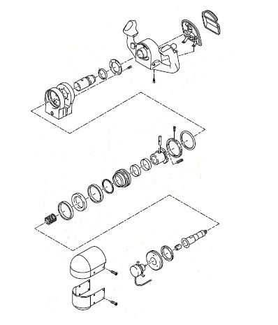
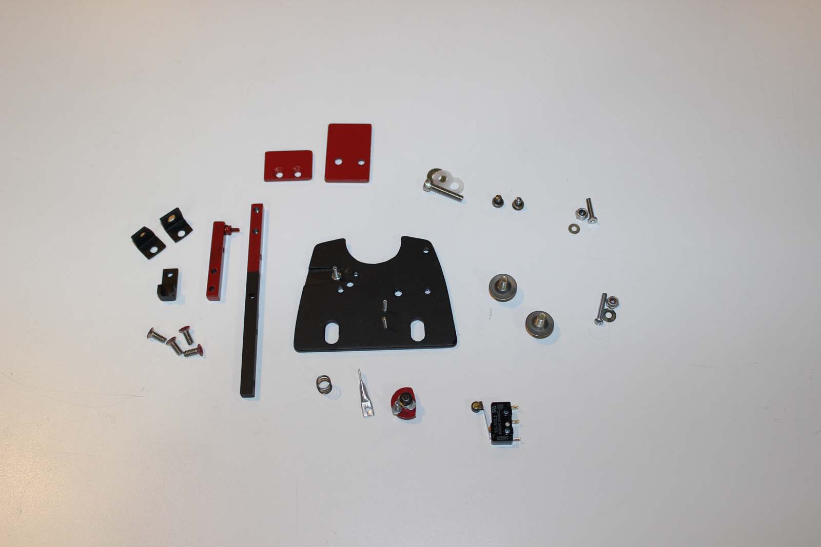
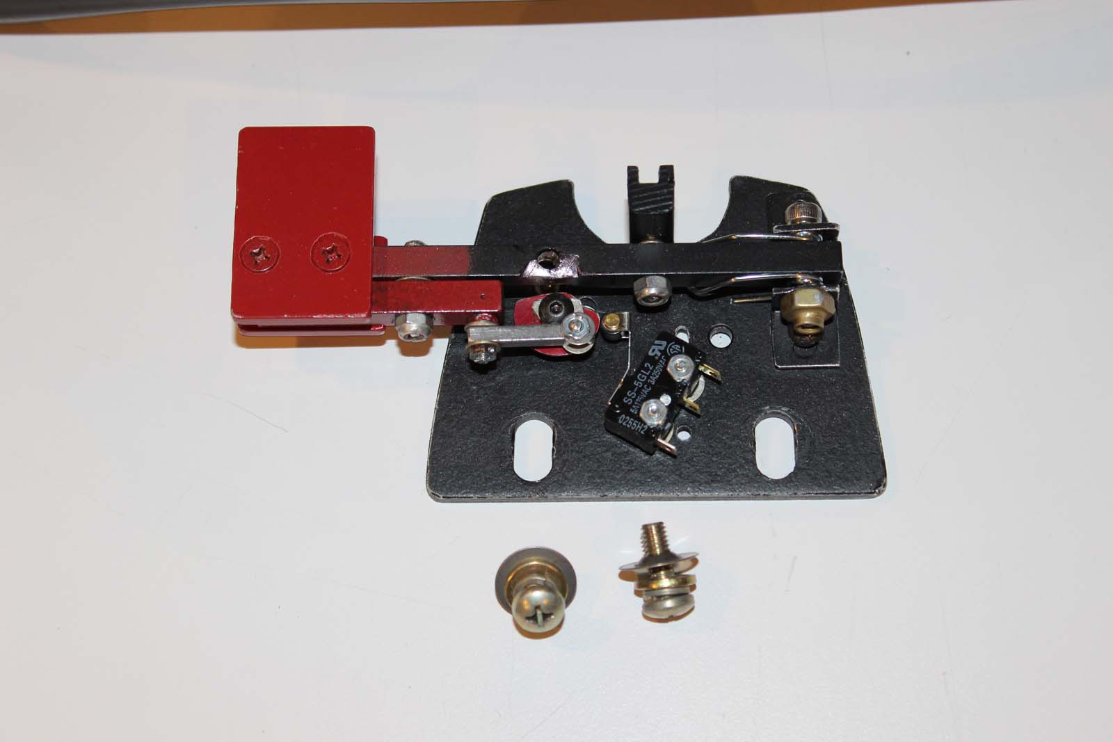
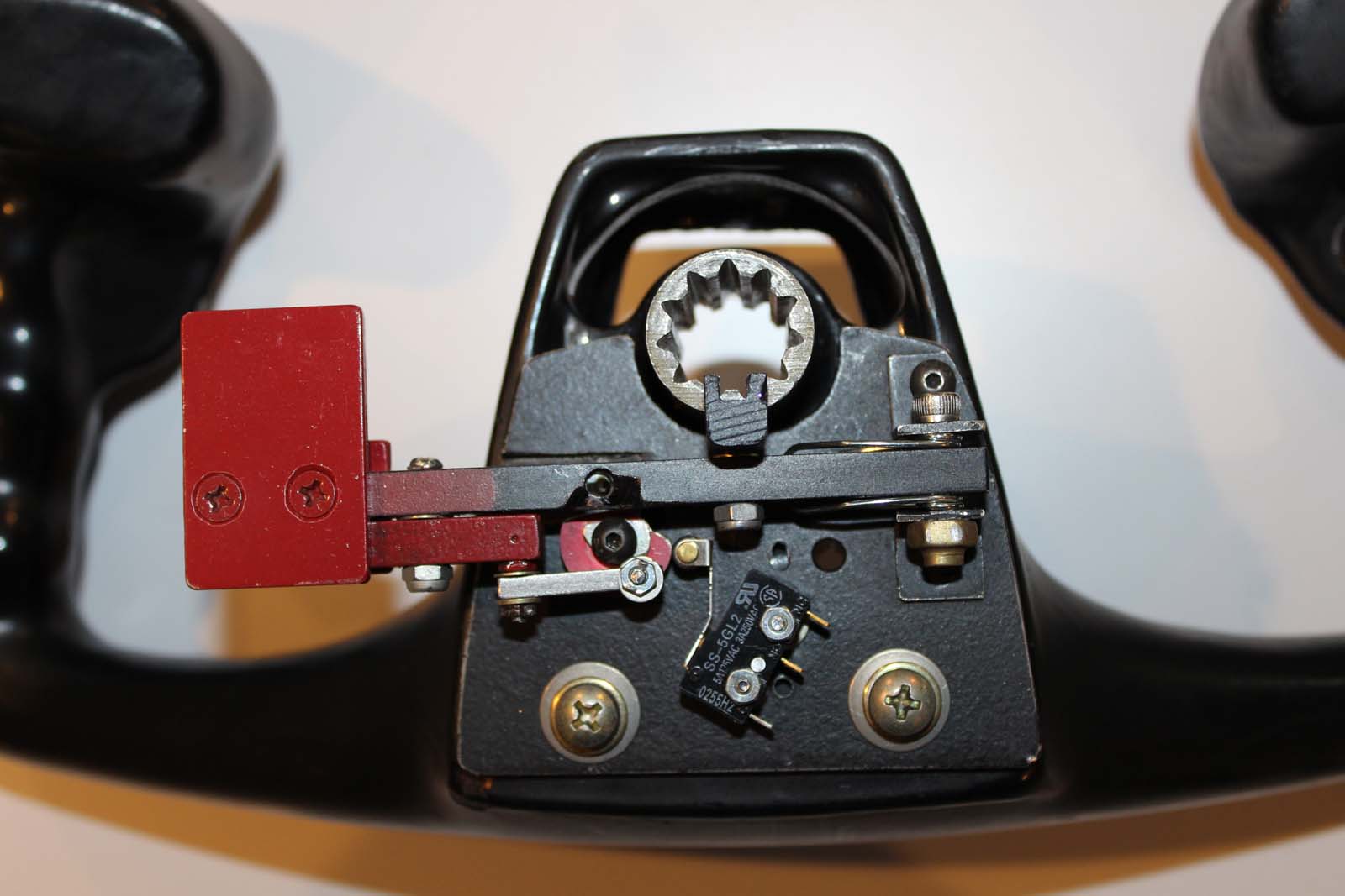
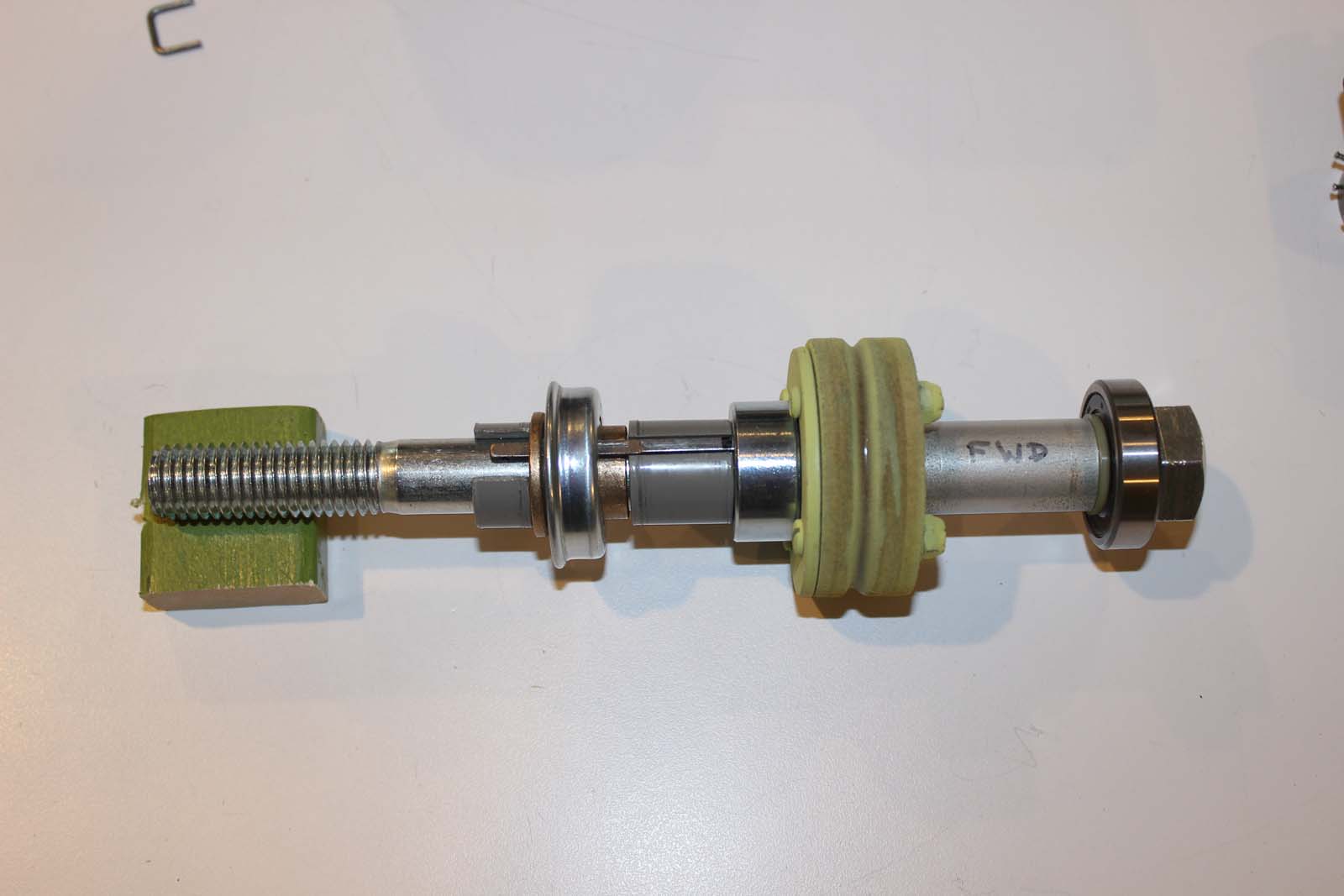
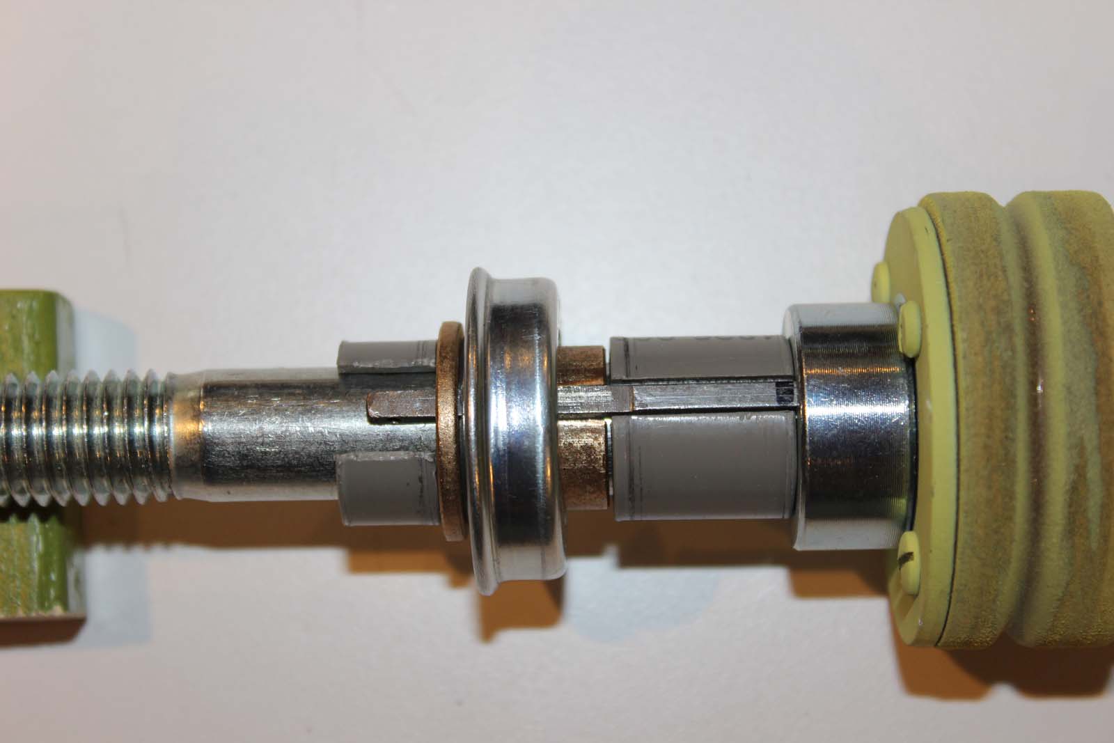
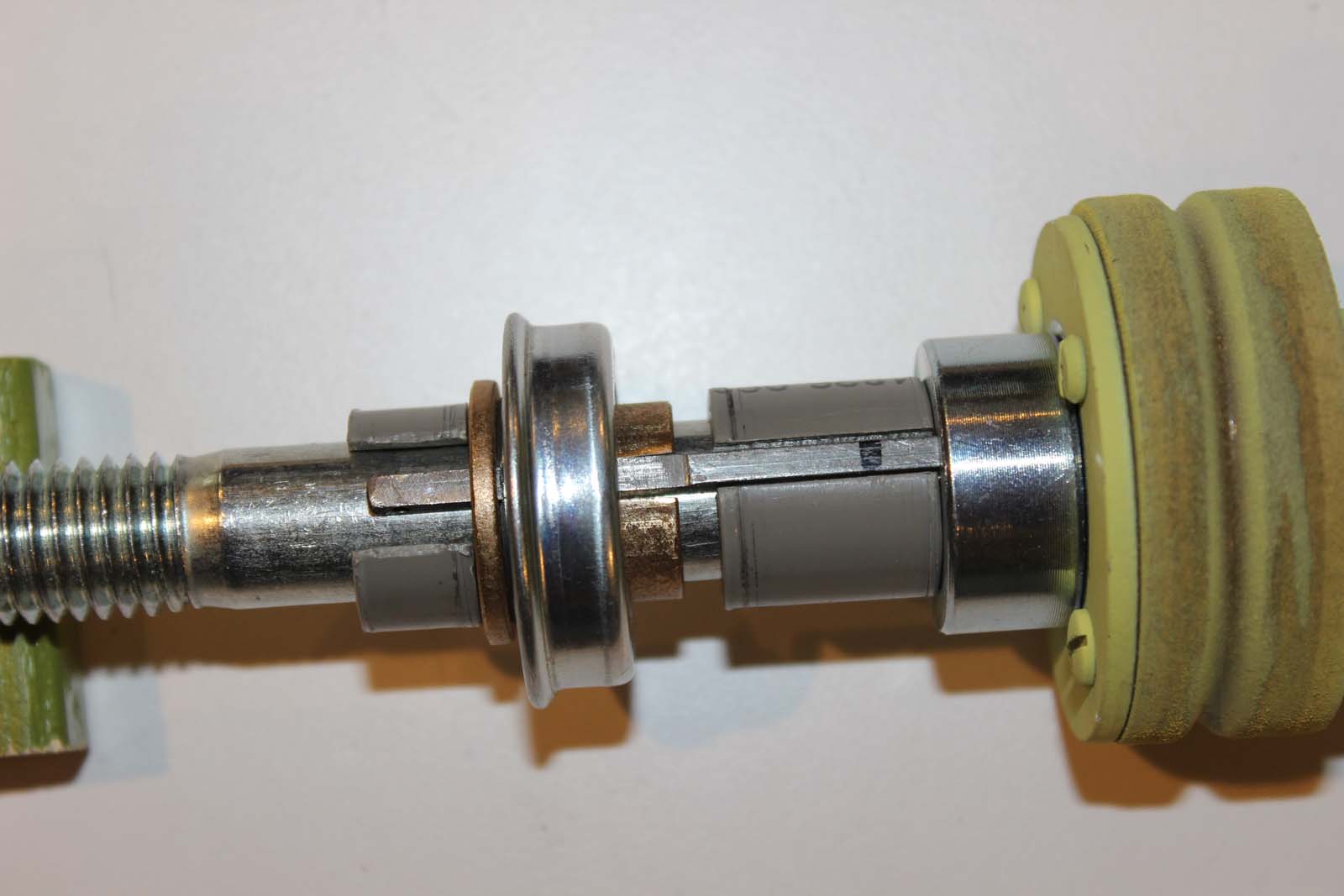
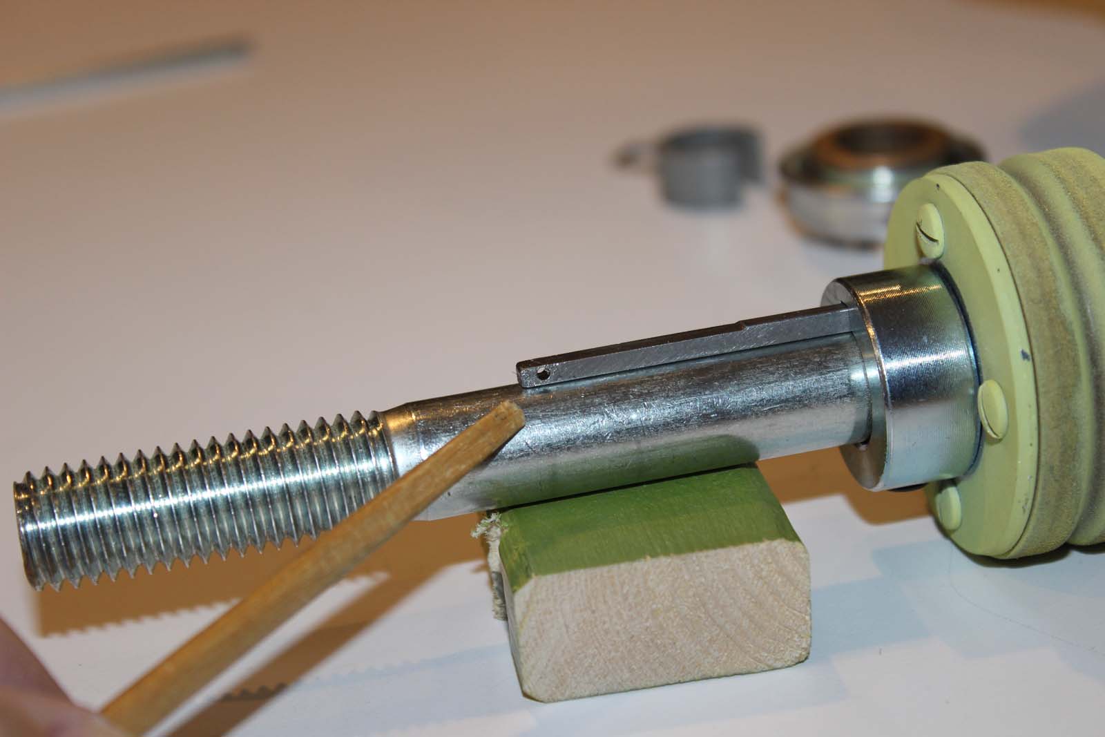
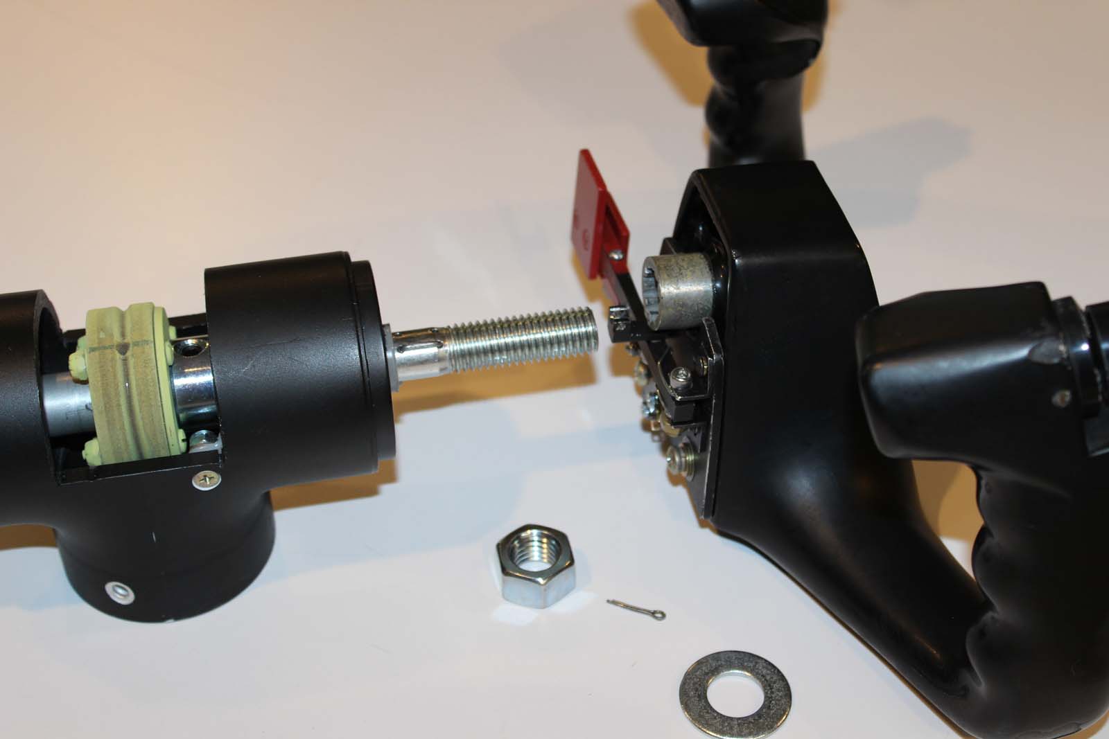
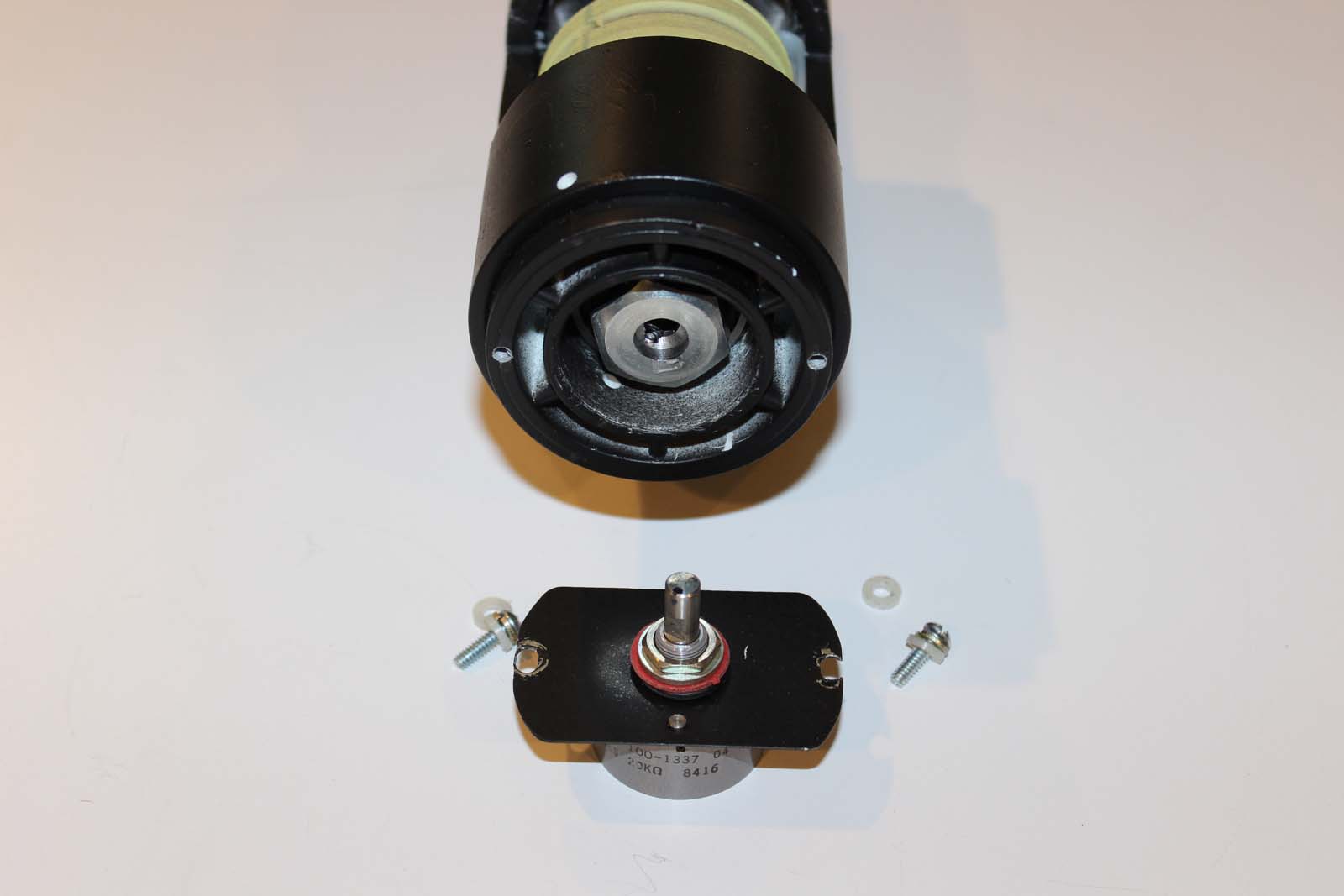
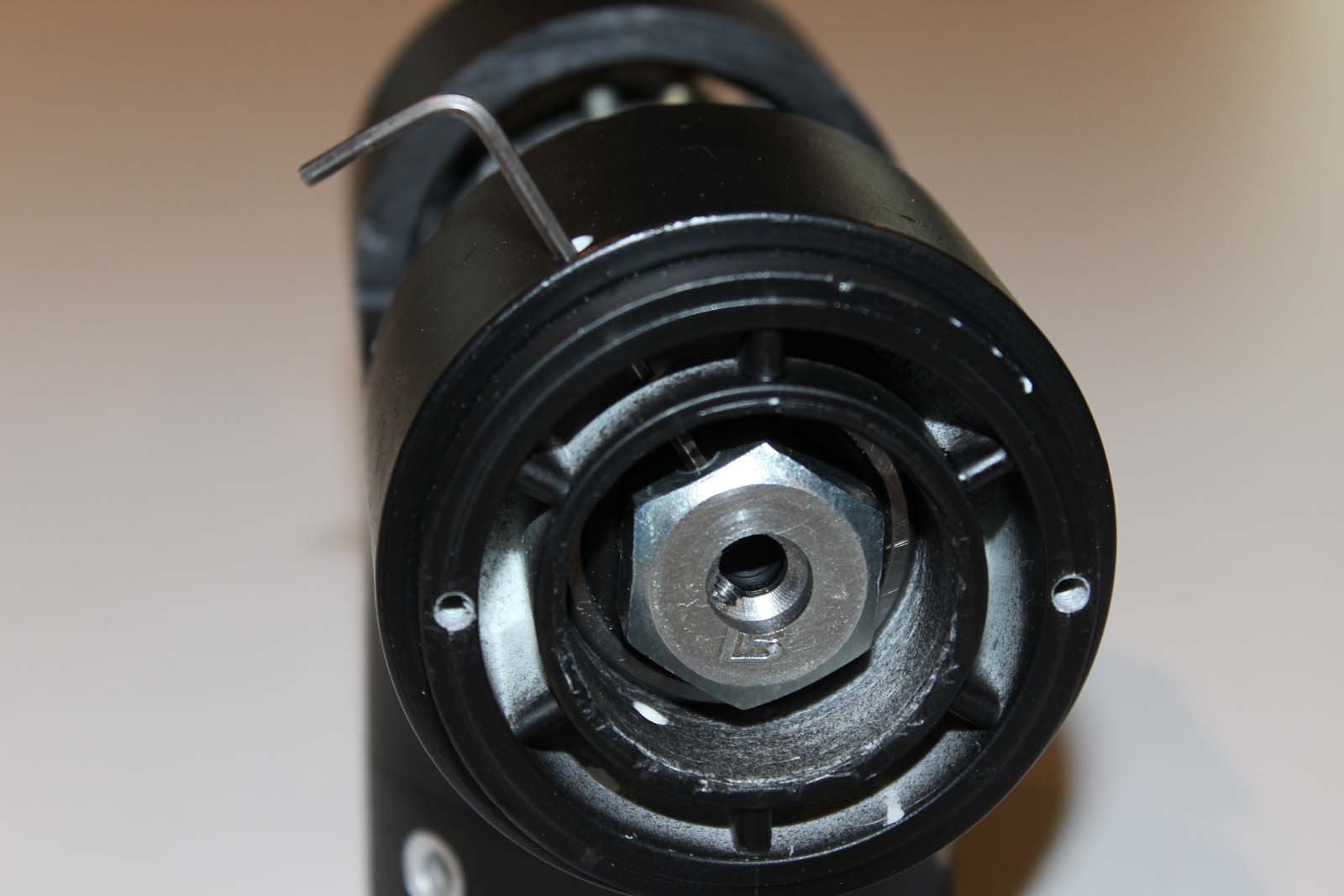
Lear 45-1001 Build History ATA-27-10 Ailerons Rev 15 Dec 2019 The L45-1001 introduction contains useful background information on this build. If somehow you have arrived at this place and have not read the L45-1001 introduction you will find it HERE: Aileron Control: Ailerons on the Learjet 45 are controlled via cables which are connected to the cockpit control wheels. A system of pulleys carries the cables between the cockpit and the control surfaces out on each wing. The autopilot roll servo is located near the wing center and is interconnected to the cable system serving the ailerons. I don’t have “wings” or physical ailerons on my simulator so it would seem unnecessary to replicate the control cable system. But I do have a 3-axis flight control system (autopilot) including servo motors. These servo motors were originally made for Edo-Aire Mitchell autopilot systems and are used in many general aviation aircraft. They are designed to be used with cable-type control systems. Replicating a portion of the aileron control cable system is necessary to use these servo motors. L45-1001 contains three separate servos, one for roll, pitch, and yaw. Each servo assembly includes a drive motor and electrically controlled clutch. I chose these particular servos because they are inexpensive and readily available from aircraft salvage companies, they include the pulley and clutch system, and they are easy to overhaul and maintain. Aileron control wheel hubs: Each control wheel is mounted to a mechanical hub located on top of the control column. The left side hub is different from the right side hub because it contains the mechanism for the aileron disconnect clutch. An important consideration for control wheel hubs is the method of attaching the control wheel itself. A simple method for removing the control wheel easily is very helpful because you will find occasions during building when you need to temporarily remove the control wheels. The method illustrated here requires a single flat washer and nut to fasten the entire hub mechanism and control wheel together. Right side hub: The right control wheel hub is simple in construction. The housing is made from a common PVC plumbing tee. Reducers in the ends of the tee provide an easy method of mounting standard sized ball bearings for the control shaft. These are the parts needed for the right side hub. Everything you see in this photo is locally fabricated from common materials except the control cable pulley. Further along in this description you will notice that the left side control cable pulley is made in a different manner. The very nice aluminum pulley in the photo below worked very well, but they are special items, expensive, and hard to find. After I made this prototype I changed the design to use the pulley you see on the left side. Both work equally well, but the revised part can be made from common materials at a fraction of the cost of the aluminum pulley. Both versions are shown here so that the reader can make his/her own decision as to which pulley to use. Wiring for the control wheel switches must pass through the control hub. The first version I made used flat cable for the “pass through” section of the wiring. It works well because it is flat and does not intrude into the operating cavity of the hub. Pass the wiring down through the lower opening of the tee. Pass the control wheel end through a slot in the aft end of the hub housing and the slot in the control wheel. Here is the hub with the assembled mechanical parts installed. Notice how the flat cable avoids the moving parts in the hub cavity. The flat cable comes out inside the center of the control wheel. After the photos above were taken I changed the design to use round multi-conductor shielded cable. I changed this because the wiring should be shielded to prevent erratic operation of the control wheel switch circuits. The round cable is routed along a similar pathway to avoid contact with the moving parts inside the hub. A single piece of the round cable provides enough conductors to service all of the circuits in the control wheel including power for the chart holder lighting. This cable is Belden type 9809. Apply Teflon tape to the section of the wiring where it passes through the hub and the control wheel slot. This protects the wiring from wear. Here is the assembled right side control wheel and hub with the chart holder installed. Control column base fitting: Each control column is attached to the torque tube (crossover tube) using a base fitting made from a PVC plumbing part. A slot is cut into the aft side of the base to provide an exit pathway for the aileron control cable. In the real aircraft this part is a custom cast and machined piece. This PVC substitute does not exactly replicate the cast part, but it is close enough to provide adequate performance. A slot in the torque tube allows the crossover pulley to intrude into the tube interior and align with the control cable. This photo was taken on the left side. The right side is a mirror image of the left. The torque tube was pulled out from normal position in order to take this photo. Normally the end of the tube is flush with the bearing. The base fitting provides a mounting for two control cable pulleys. One pulley carries the control cable across and through the torque tube. The other pulley provides an exit pathway for the control cable as it travels aft to the aileron servo. This photo is the right side base fitting. The top of the photo is “aft” in the airframe. A slot in the control column and base fitting align to provide an exit path for the control cable. Here is a view looking "down" the inside of the control column from the top. The base fitting is seen at the bottom of the column. This photo illustrates how the cable pulleys offset the cable to obtain adequate clearance. This photo shows how the pulley intrudes into the torque tube interior space. The control column base fitting is mounted on the torque tube and ready for installation of the control column. NOTICE the piece of waxed lacing twine pre-installed in the torque tube. This is used in a manner similar to the way an electrician uses a “pull line” to install wiring into conduit after it has been assembled. A pull line is VERY HELPFUL for installing the control cable after the columns and control wheel hubs are installed. Here is the right side control column installed on the crossover torque tube. Secure the pull line so that it does not become dislodged during assembly of the left control column parts. Both control columns and control wheel hubs are installed and ready for installation of the control cables and wiring. Left side hub: An aileron disconnect system is provided on the Learjet 45 as a backup means of retaining aircraft roll control in the event of a problem with the aileron system. Ailerons are located out on the wings where they are exposed to hazards such as bird strikes, debris ingress, ice accumulation, and physical damage. Should the aileron system become jammed the crew can use the aileron disconnect clutch to regain roll control. “Pulling” the aileron disconnect paddle mechanically separates the pilot’s control WHEEL from the control CABLE system. This action also activates the spoileron system. The spoileron system uses the spoilers in a differential mode to provide roll control, even if the aileron surfaces are stuck. A sensor on the forward end of the left control wheel hub tracks the position of the LEFT control wheel and uses this information to control the spoilerons. In this manner a redundant system of roll control is provided for the Learjet 45. As you might imagine the aileron clutch requires a double-handful of complex parts. However, a simplified version of it can be built from common materials and parts. Someone will surely ask, “Why bother to replicate the aileron disconnect since we don’t have physical ailerons in our sims?” Answer: “Train like you fly – fly like you train”. We don’t have physical landing gear either, but nobody would suggest leaving out the gear switch, brakes, or nosewheel steering! The figure below illustrates the complexity of the real aileron disconnect clutch mechanism. We’re not building this one! The photo below is the parts needed for a simplified version of the aileron disconnect clutch control lever. All of these are either common parts or were fabricated from common materials. The aileron disconnect clutch control lever parts are assembled on the adapter plate. The adapter plate is made from a piece of 0.125” aluminum. The adapter plate fastens to the hub of the control wheel with two 10-32 screws. Holes for these screws are drilled and tapped in the hub of the control wheel. In a real Lear 45 control wheel the hub is much larger in size. Most of the parts shown on this adapter plate are mounted inside the control wheel hub. The control wheels in these photos are from a Lear 35 aircraft. The Lear 35 doesn't have an aileron disconnect system thus the control wheel hubs are much smaller. In order to use non-Lear 45 control wheels with an aileron disconnect system these parts must be mounted external to the hub as shown. The left side control shaft and clutch parts assembled on the shaft. This photo shows the revised version of the control cable pulley. This is the version in use on L45-1001. It is not obvious in this photo but the cable groove was coated with three applications of epoxy before the cable was installed to prevent excessive wear of the pulley. These photos illustrate the action of the clutch parts. The essential moving part of the clutch is the long “key” that runs side-to-side in the photo. The key only has to move about 0.125” between the “engaged” and “released” positions. Notice the position of a small black mark on the key to see how much it moves. The key passes through the shaft collar and extends into a notch cut in the pulley face plate. The pulley face plate is approximately 0.125” thick, thus the key travel must be sufficient to clear the plate when the clutch is released. In these photos it appears that the bearing and sleeve on the left side moves with the key but this is not correct. Only the "key" moves when the shaft assembly is installed in the hub housing. I didn't notice this when I took these photos, but I see it now that I'm posting them. My apologies. Don't be confused: Only the key moves. The key has a small hole in the end. A cotter key passes through a mating part on the disconnect clutch control lever and attaches the lever to the key. This allows the control lever to move the key longitudinally along the shaft and operate the clutch. The parts in the hub are assembled and ready for installation of the control wheel. The control wheel has the clutch control lever assembly installed and is ready for mating to the hub shaft. At this point in assembly the remaining parts needed are the cotter pin, a flat washer, and the nut which holds the control wheel in place on the shaft. Assembly tip: Use an ordinary nut until you are ready for final assembly. At final assembly use a self-locking NyLoc type nut. This makes it easy to remove the control wheel until you are ready for final assembly. The forward end of the hub provides a mounting location for the spoileron sensor. Use a thin piece of material to make the sensor mounting plate. Elongate the mounting holes in the mounting plate to provide a method of fine calibration for the sensor. The center of the hub shaft is drilled to accept the spoileron sensor shaft. The head of the hub shaft is drilled and tapped for two setscrews. A hole in the forward end of the hub provides access for an Allen wrench to tighten the setscrews. Tighten the first set screw, then rotate the control wheel until the second setscrew aligns with the hole. Then tighten the second set screw. IMPORTANT: “Center” the sensor shaft before tightening the set screws. The sensor (pot) should be at 50% travel when the control wheel is centered. Mount the spoileron sensor to the forward end of the hub. Tip: USE A HIGH QUALITY POT! Here is the left side control wheel and hub assembled and ready for installation. The aileron disconnect lever pulled into the “Disconnect” position. The lower half of the paddle is a guard that helps to prevent unintentional operation of the clutch. “Pulling” the paddle aft moves the guard with it to the disconnect position. The guard then acts as a lock to prevent re-engagement of the clutch. To re-engage the clutch, the guard must be manually moved out of the locked position before the paddle can be “pushed” (forward) back to the engaged position. Here is the finished left side control wheel installed and ready for rigging. HOME: This link goes to the L45-1001 build history introduction. Links to other L45-1001 posts are found at the END of the introduction. Lear 45-1001 Build History ATA-27-10 Ailerons Rev 15 Dec 2019 The L45-1001 introduction contains useful background information on this build. If somehow you have arrived at this place and have not read the L45-1001 introduction you will find it HERE: Aileron Control: Ailerons on the Learjet 45 are controlled via cables which are connected to the cockpit control wheels. A system of pulleys carries the cables between the cockpit and the control surfaces out on each wing. The autopilot roll servo is located near the wing center and is interconnected to the cable system serving the ailerons. I don’t have “wings” or physical ailerons on my simulator so it would seem unnecessary to replicate the control cable system. But I do have a 3-axis flight control system (autopilot) including servo motors. These servo motors were originally made for Edo-Aire Mitchell autopilot systems and are used in many general aviation aircraft. They are designed to be used with cable-type control systems. Replicating a portion of the aileron control cable system is necessary to use these servo motors. L45-1001 contains three separate servos, one for roll, pitch, and yaw. Each servo assembly includes a drive motor and electrically controlled clutch. I chose these particular servos because they are inexpensive and readily available from aircraft salvage companies, they include the pulley and clutch system, and they are easy to overhaul and maintain. Aileron control wheel hubs: Each control wheel is mounted to a mechanical hub located on top of the control column. The left side hub is different from the right side hub because it contains the mechanism for the aileron disconnect clutch. An important consideration for control wheel hubs is the method of attaching the control wheel itself. A simple method for removing the control wheel easily is very helpful because you will find occasions during building when you need to temporarily remove the control wheels. The method illustrated here requires a single flat washer and nut to fasten the entire hub mechanism and control wheel together. Right side hub: The right control wheel hub is simple in construction. The housing is made from a common PVC plumbing tee. Reducers in the ends of the tee provide an easy method of mounting standard sized ball bearings for the control shaft. These are the parts needed for the right side hub. Everything you see in this photo is locally fabricated from common materials except the control cable pulley. Further along in this description you will notice that the left side control cable pulley is made in a different manner. The very nice aluminum pulley in the photo below worked very well, but they are special items, expensive, and hard to find. After I made this prototype I changed the design to use the pulley you see on the left side. Both work equally well, but the revised part can be made from common materials at a fraction of the cost of the aluminum pulley. Both versions are shown here so that the reader can make his/her own decision as to which pulley to use. Wiring for the control wheel switches must pass through the control hub. The first version I made used flat cable for the “pass through” section of the wiring. It works well because it is flat and does not intrude into the operating cavity of the hub. Pass the wiring down through the lower opening of the tee. Pass the control wheel end through a slot in the aft end of the hub housing and the slot in the control wheel. Here is the hub with the assembled mechanical parts installed. Notice how the flat cable avoids the moving parts in the hub cavity. The flat cable comes out inside the center of the control wheel. After the photos above were taken I changed the design to use round multi-conductor shielded cable. I changed this because the wiring should be shielded to prevent erratic operation of the control wheel switch circuits. The round cable is routed along a similar pathway to avoid contact with the moving parts inside the hub. A single piece of the round cable provides enough conductors to service all of the circuits in the control wheel including power for the chart holder lighting. This cable is Belden type 9809. Apply Teflon tape to the section of the wiring where it passes through the hub and the control wheel slot. This protects the wiring from wear. Here is the assembled right side control wheel and hub with the chart holder installed. Control column base fitting: Each control column is attached to the torque tube (crossover tube) using a base fitting made from a PVC plumbing part. A slot is cut into the aft side of the base to provide an exit pathway for the aileron control cable. In the real aircraft this part is a custom cast and machined piece. This PVC substitute does not exactly replicate the cast part, but it is close enough to provide adequate performance. A slot in the torque tube allows the crossover pulley to intrude into the tube interior and align with the control cable. This photo was taken on the left side. The right side is a mirror image of the left. The torque tube was pulled out from normal position in order to take this photo. Normally the end of the tube is flush with the bearing. The base fitting provides a mounting for two control cable pulleys. One pulley carries the control cable across and through the torque tube. The other pulley provides an exit pathway for the control cable as it travels aft to the aileron servo. This photo is the right side base fitting. The top of the photo is “aft” in the airframe. A slot in the control column and base fitting align to provide an exit path for the control cable. Here is a view looking "down" the inside of the control column from the top. The base fitting is seen at the bottom of the column. This photo illustrates how the cable pulleys offset the cable to obtain adequate clearance. This photo shows how the pulley intrudes into the torque tube interior space. The control column base fitting is mounted on the torque tube and ready for installation of the control column. NOTICE the piece of waxed lacing twine pre-installed in the torque tube. This is used in a manner similar to the way an electrician uses a “pull line” to install wiring into conduit after it has been assembled. A pull line is VERY HELPFUL for installing the control cable after the columns and control wheel hubs are installed. Here is the right side control column installed on the crossover torque tube. Secure the pull line so that it does not become dislodged during assembly of the left control column parts. Both control columns and control wheel hubs are installed and ready for installation of the control cables and wiring. Left side hub: An aileron disconnect system is provided on the Learjet 45 as a backup means of retaining aircraft roll control in the event of a problem with the aileron system. Ailerons are located out on the wings where they are exposed to hazards such as bird strikes, debris ingress, ice accumulation, and physical damage. Should the aileron system become jammed the crew can use the aileron disconnect clutch to regain roll control. “Pulling” the aileron disconnect paddle mechanically separates the pilot’s control WHEEL from the control CABLE system. This action also activates the spoileron system. The spoileron system uses the spoilers in a differential mode to provide roll control, even if the aileron surfaces are stuck. A sensor on the forward end of the left control wheel hub tracks the position of the LEFT control wheel and uses this information to control the spoilerons. In this manner a redundant system of roll control is provided for the Learjet 45. As you might imagine the aileron clutch requires a double-handful of complex parts. However, a simplified version of it can be built from common materials and parts. Someone will surely ask, “Why bother to replicate the aileron disconnect since we don’t have physical ailerons in our sims?” Answer: “Train like you fly – fly like you train”. We don’t have physical landing gear either, but nobody would suggest leaving out the gear switch, brakes, or nosewheel steering! The figure below illustrates the complexity of the real aileron disconnect clutch mechanism. We’re not building this one! The photo below is the parts needed for a simplified version of the aileron disconnect clutch control lever. All of these are either common parts or were fabricated from common materials. The aileron disconnect clutch control lever parts are assembled on the adapter plate. The adapter plate is made from a piece of 0.125” aluminum. The adapter plate fastens to the hub of the control wheel with two 10-32 screws. Holes for these screws are drilled and tapped in the hub of the control wheel. In a real Lear 45 control wheel the hub is much larger in size. Most of the parts shown on this adapter plate are mounted inside the control wheel hub. The control wheels in these photos are from a Lear 35 aircraft. The Lear 35 doesn't have an aileron disconnect system thus the control wheel hubs are much smaller. In order to use non-Lear 45 control wheels with an aileron disconnect system these parts must be mounted external to the hub as shown. The left side control shaft and clutch parts assembled on the shaft. This photo shows the revised version of the control cable pulley. This is the version in use on L45-1001. It is not obvious in this photo but the cable groove was coated with three applications of epoxy before the cable was installed to prevent excessive wear of the pulley. These photos illustrate the action of the clutch parts. The essential moving part of the clutch is the long “key” that runs side-to-side in the photo. The key only has to move about 0.125” between the “engaged” and “released” positions. Notice the position of a small black mark on the key to see how much it moves. The key passes through the shaft collar and extends into a notch cut in the pulley face plate. The pulley face plate is approximately 0.125” thick, thus the key travel must be sufficient to clear the plate when the clutch is released. In these photos it appears that the bearing and sleeve on the left side moves with the key but this is not correct. Only the "key" moves when the shaft assembly is installed in the hub housing. I didn't notice this when I took these photos, but I see it now that I'm posting them. My apologies. Don't be confused: Only the key moves. The key has a small hole in the end. A cotter key passes through a mating part on the disconnect clutch control lever and attaches the lever to the key. This allows the control lever to move the key longitudinally along the shaft and operate the clutch. The parts in the hub are assembled and ready for installation of the control wheel. The control wheel has the clutch control lever assembly installed and is ready for mating to the hub shaft. At this point in assembly the remaining parts needed are the cotter pin, a flat washer, and the nut which holds the control wheel in place on the shaft. Assembly tip: Use an ordinary nut until you are ready for final assembly. At final assembly use a self-locking NyLoc type nut. This makes it easy to remove the control wheel until you are ready for final assembly. The forward end of the hub provides a mounting location for the spoileron sensor. Use a thin piece of material to make the sensor mounting plate. Elongate the mounting holes in the mounting plate to provide a method of fine calibration for the sensor. The center of the hub shaft is drilled to accept the spoileron sensor shaft. The head of the hub shaft is drilled and tapped for two setscrews. A hole in the forward end of the hub provides access for an Allen wrench to tighten the setscrews. Tighten the first set screw, then rotate the control wheel until the second setscrew aligns with the hole. Then tighten the second set screw. IMPORTANT: “Center” the sensor shaft before tightening the set screws. The sensor (pot) should be at 50% travel when the control wheel is centered. Mount the spoileron sensor to the forward end of the hub. Tip: USE A HIGH QUALITY POT! Here is the left side control wheel and hub assembled and ready for installation. The aileron disconnect lever pulled into the “Disconnect” position. The lower half of the paddle is a guard that helps to prevent unintentional operation of the clutch. “Pulling” the paddle aft moves the guard with it to the disconnect position. The guard then acts as a lock to prevent re-engagement of the clutch. To re-engage the clutch, the guard must be manually moved out of the locked position before the paddle can be “pushed” (forward) back to the engaged position. Here is the finished left side control wheel installed and ready for rigging. HOME: This link goes to the L45-1001 build history introduction. Links to other L45-1001 posts are found at the END of the introduction.L45-1001 ATA 27-10, Ailerons
![]()
2017-10-10