


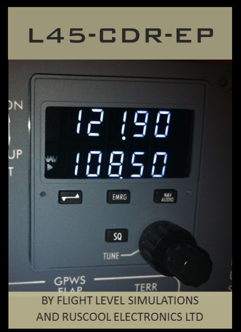
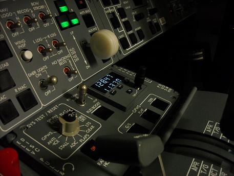
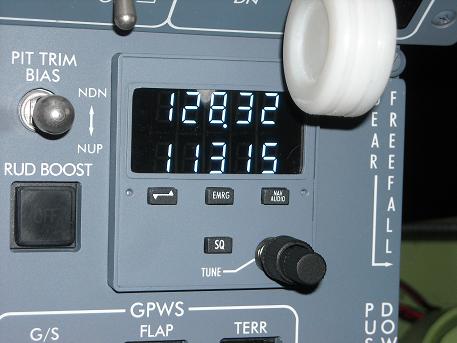
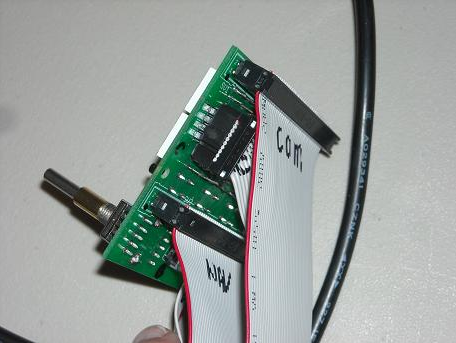
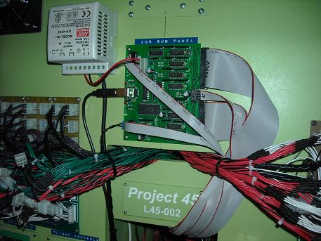
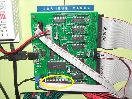
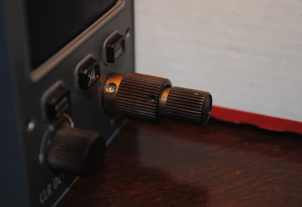
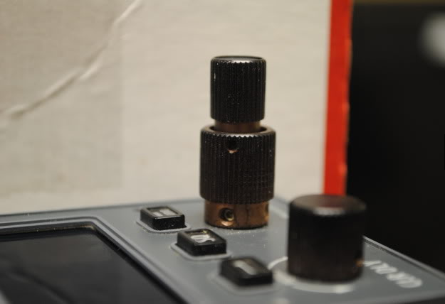
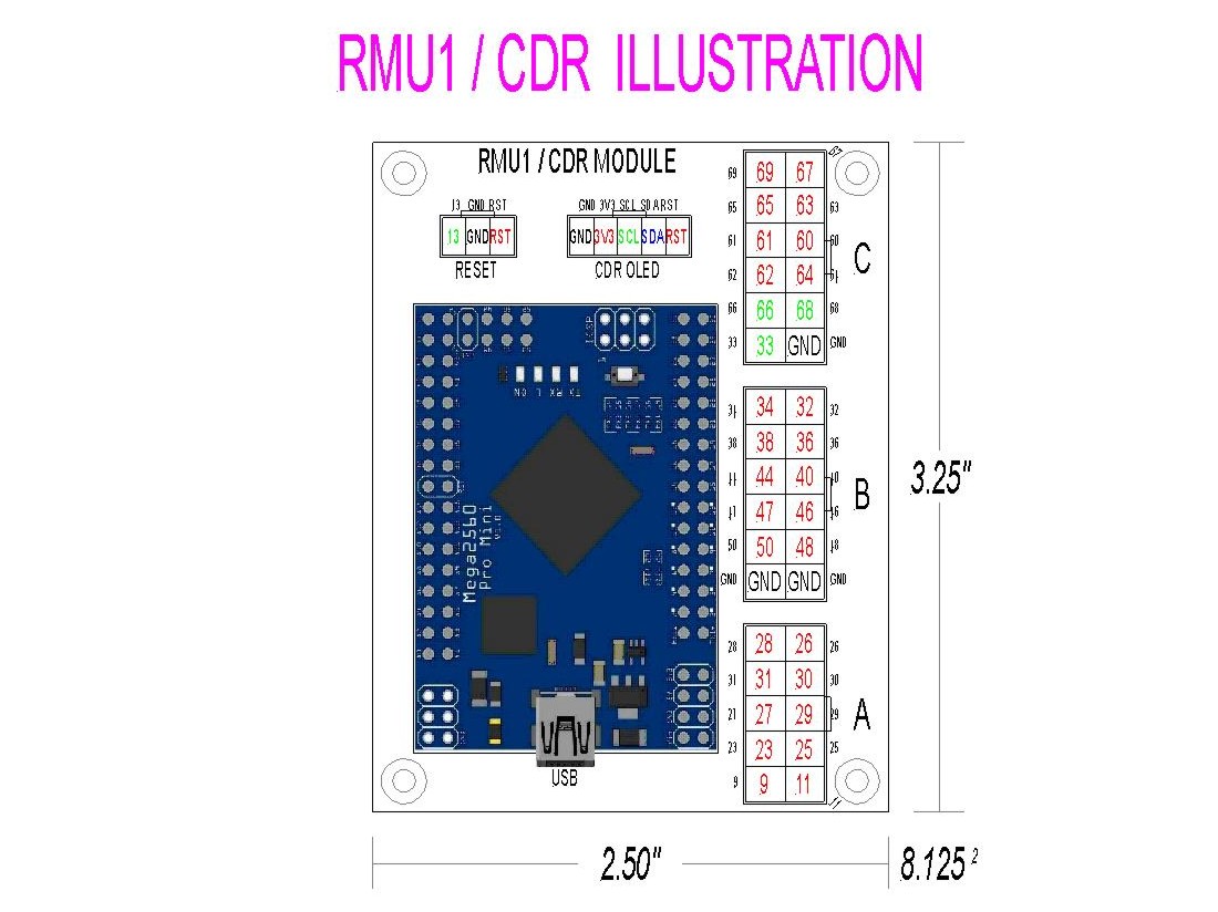
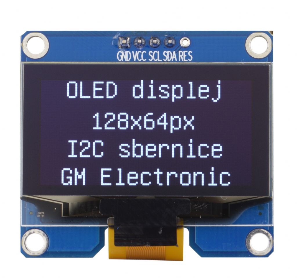
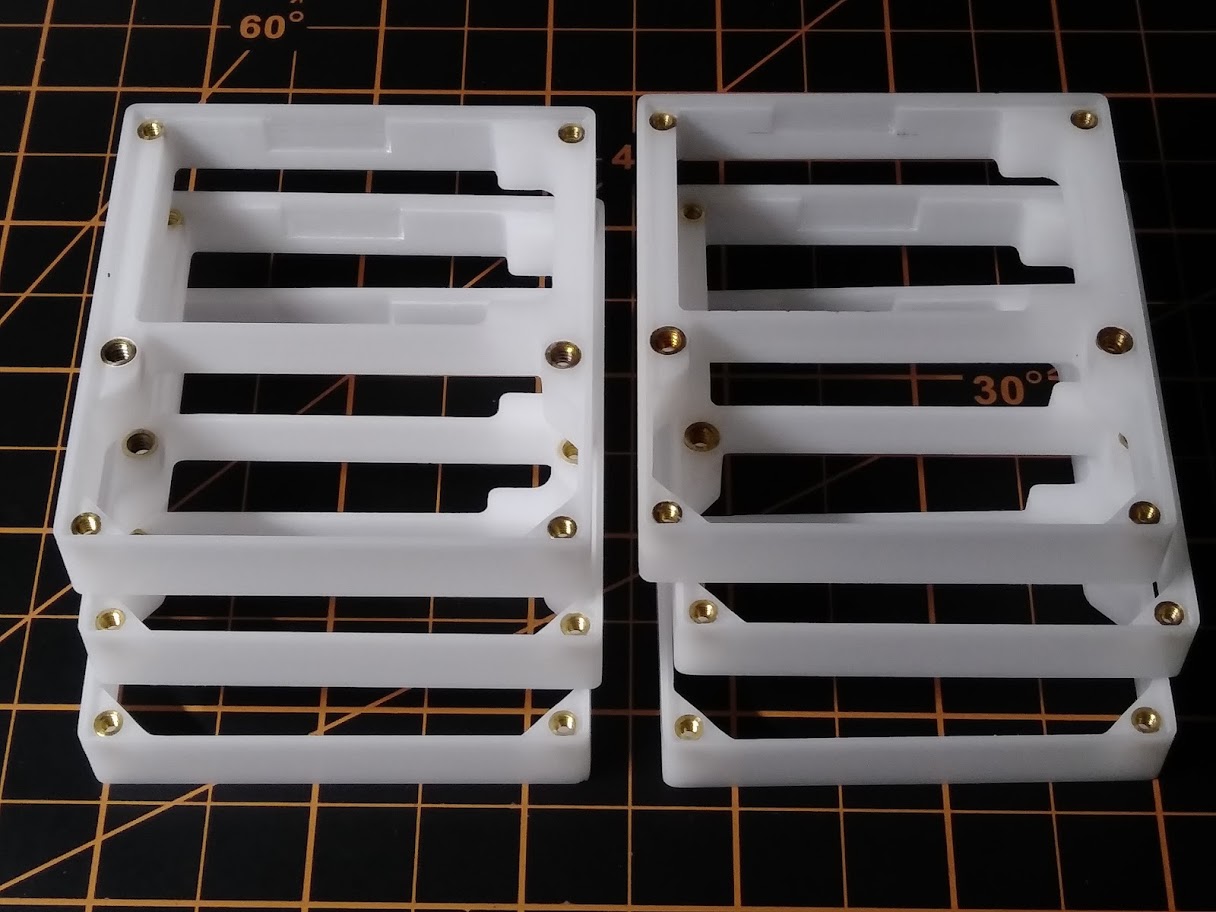
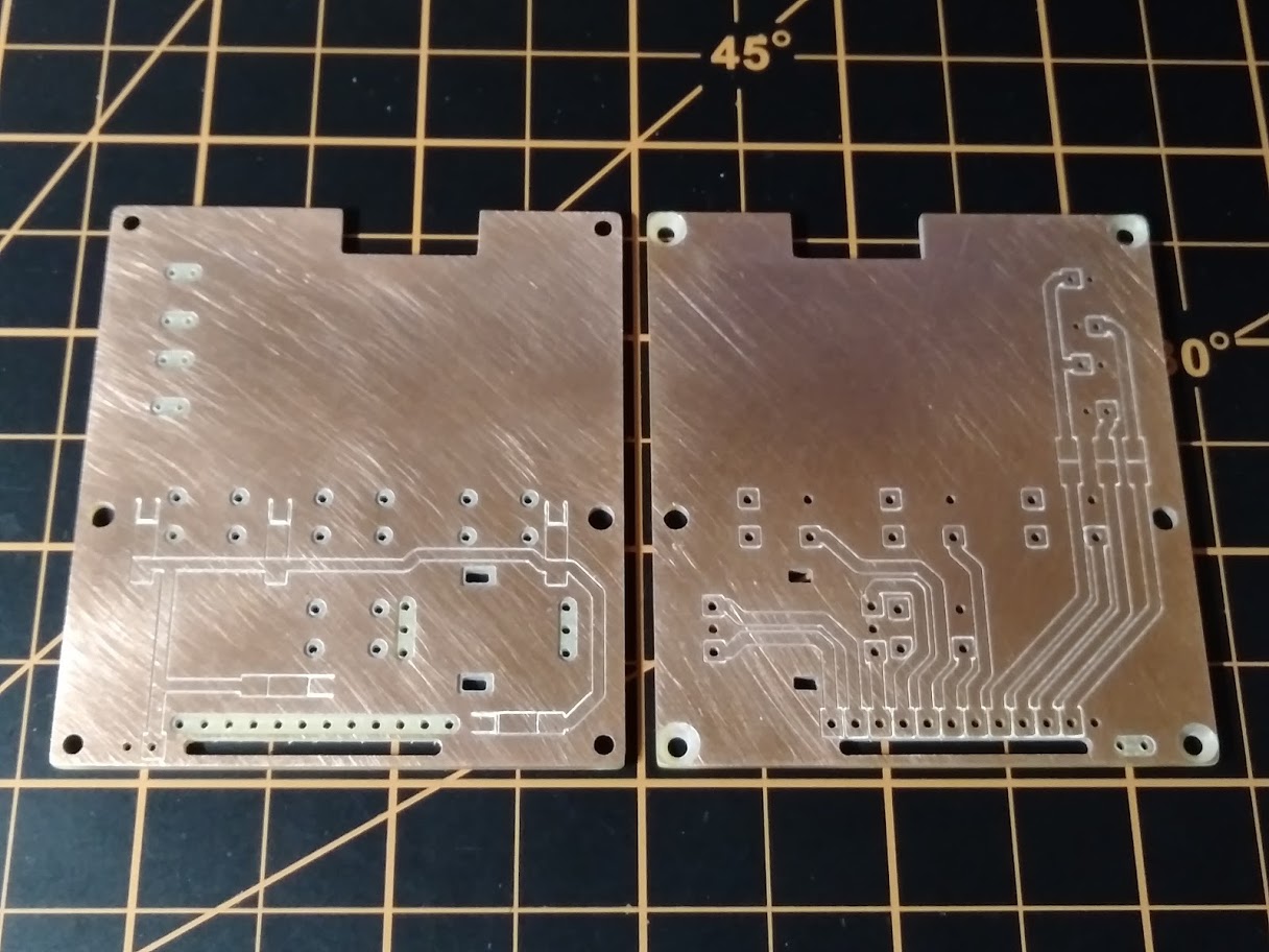
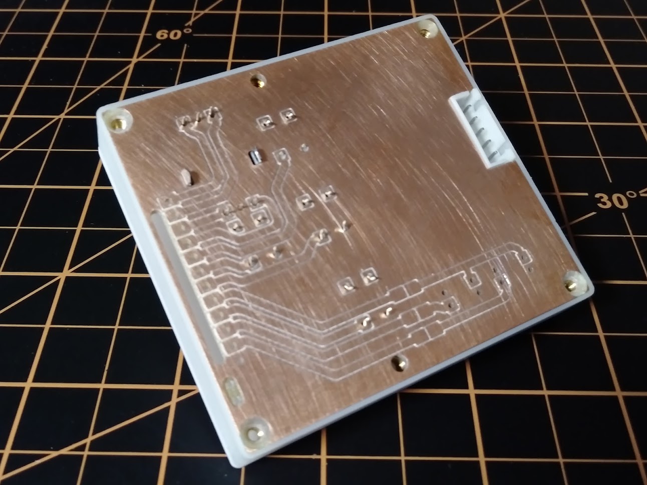
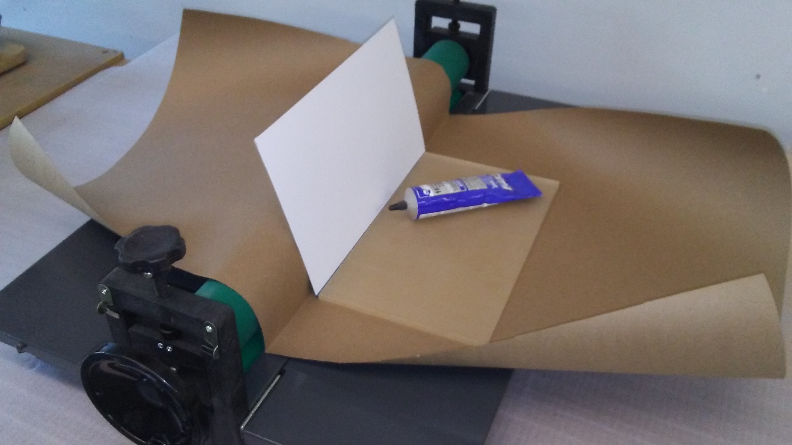
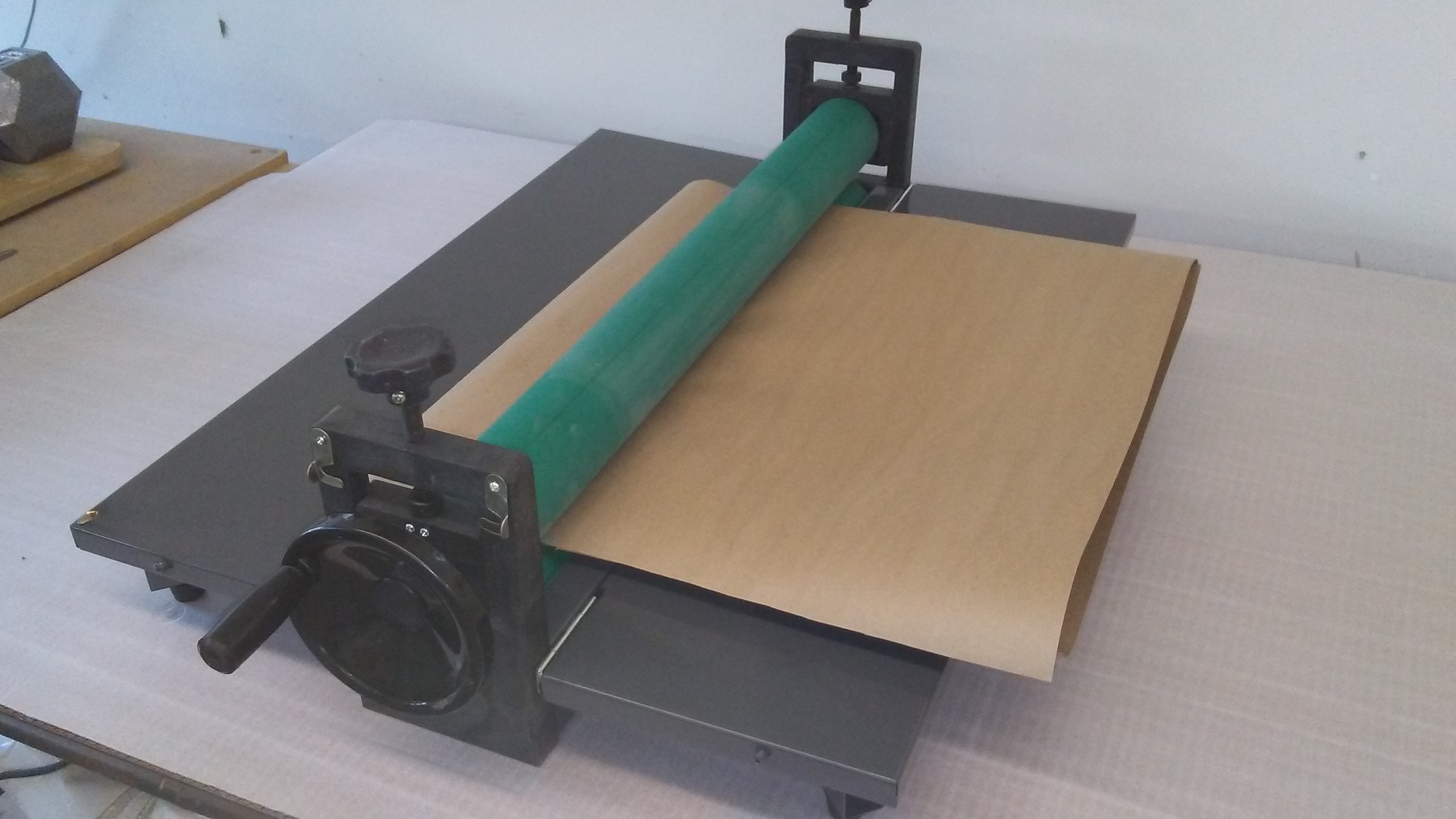
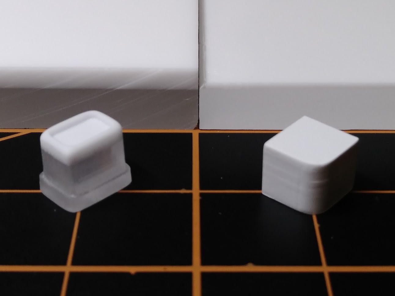
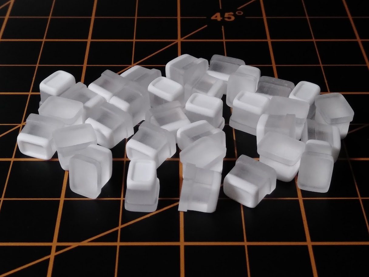
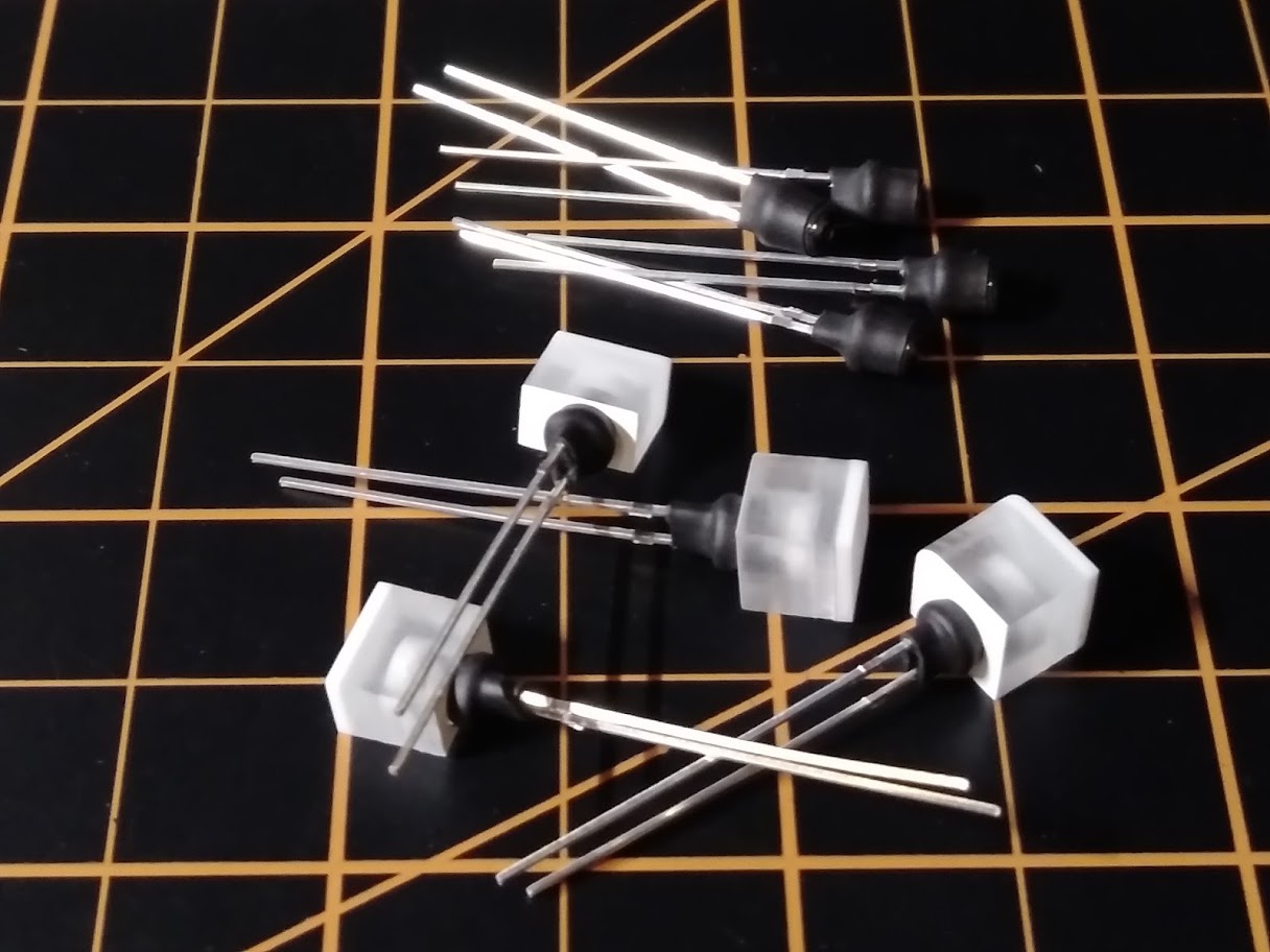
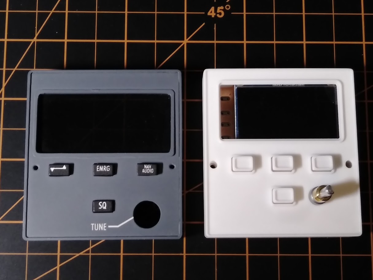
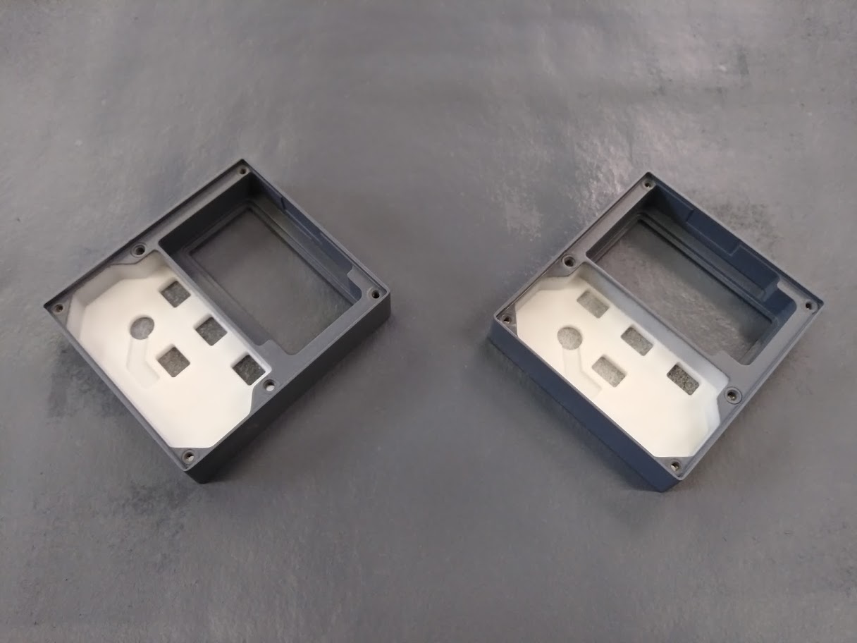
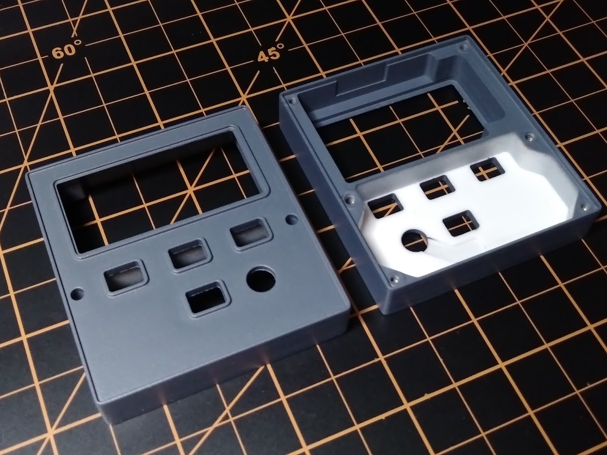
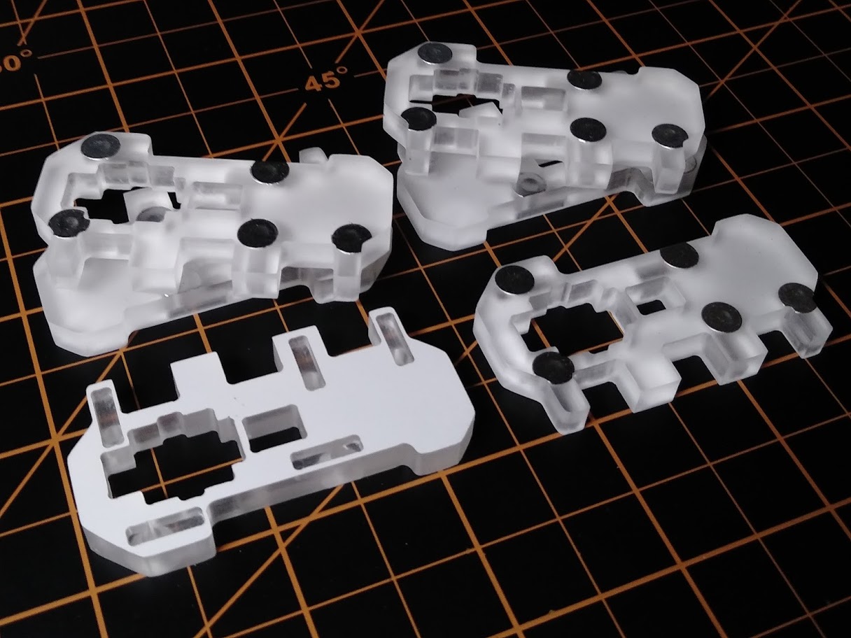
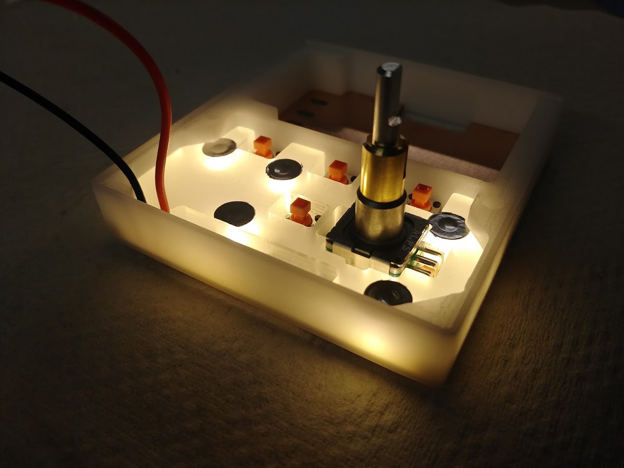
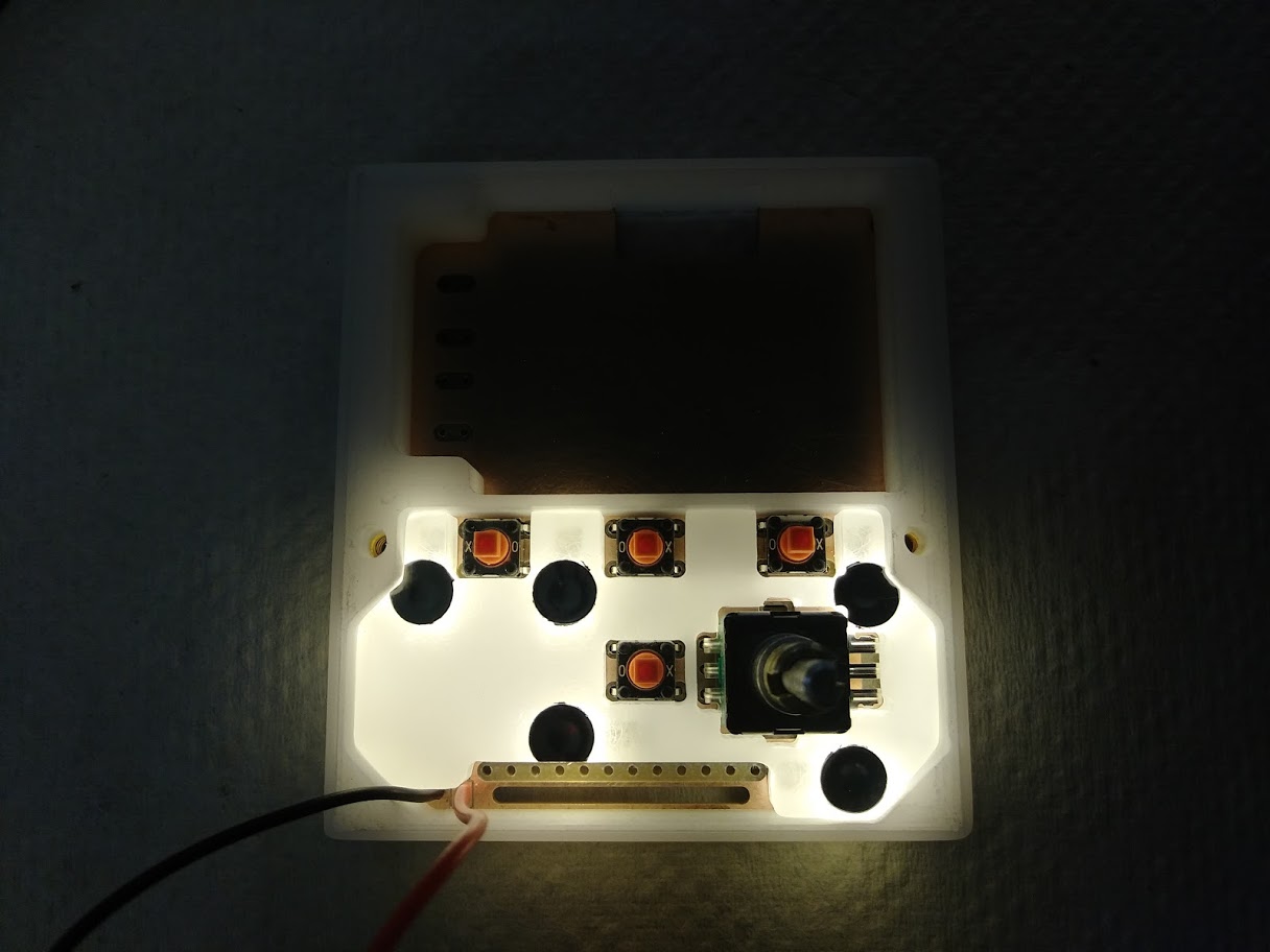
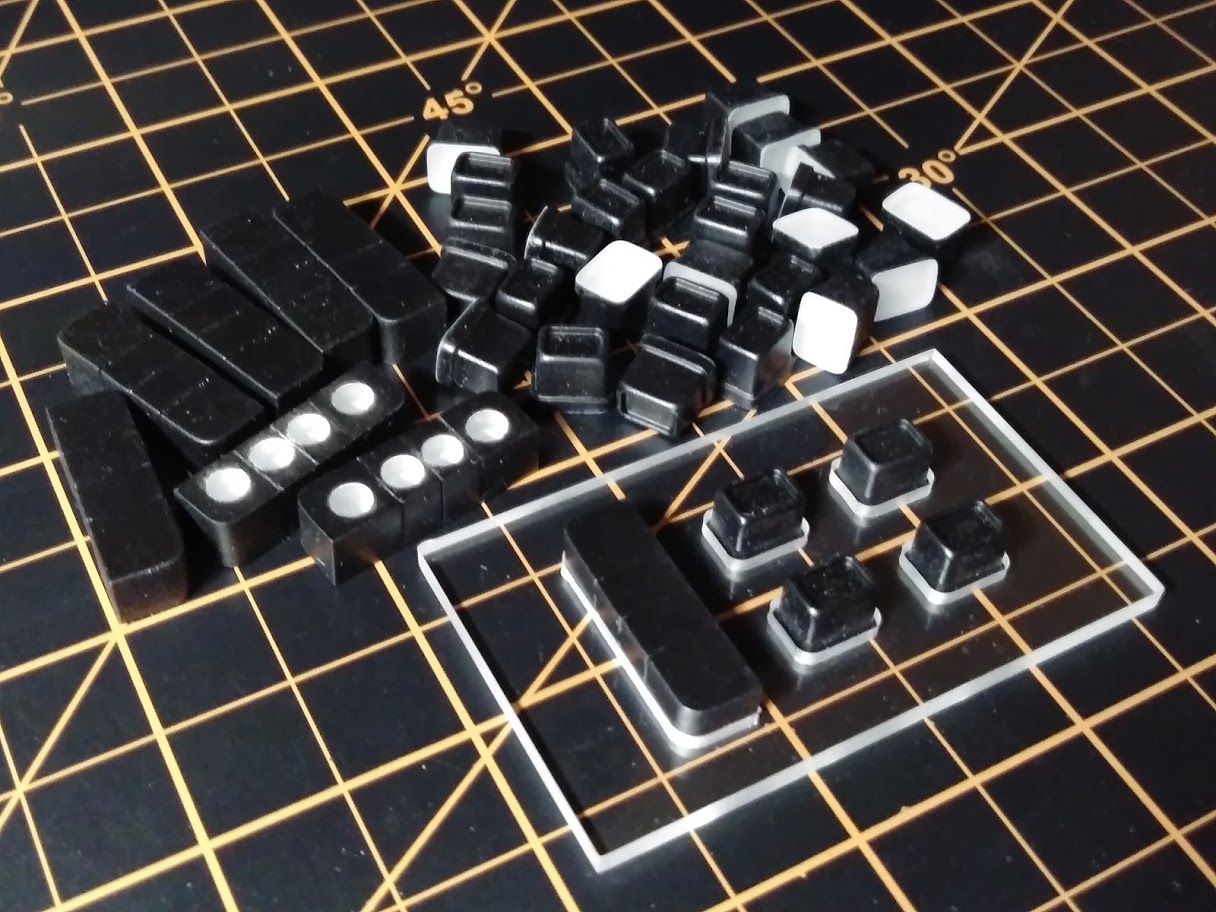
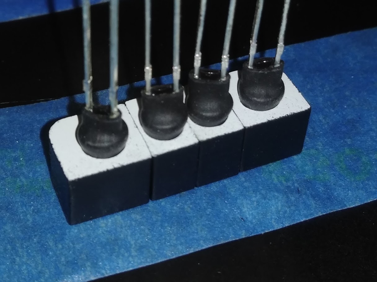
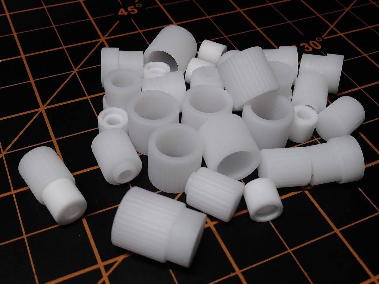
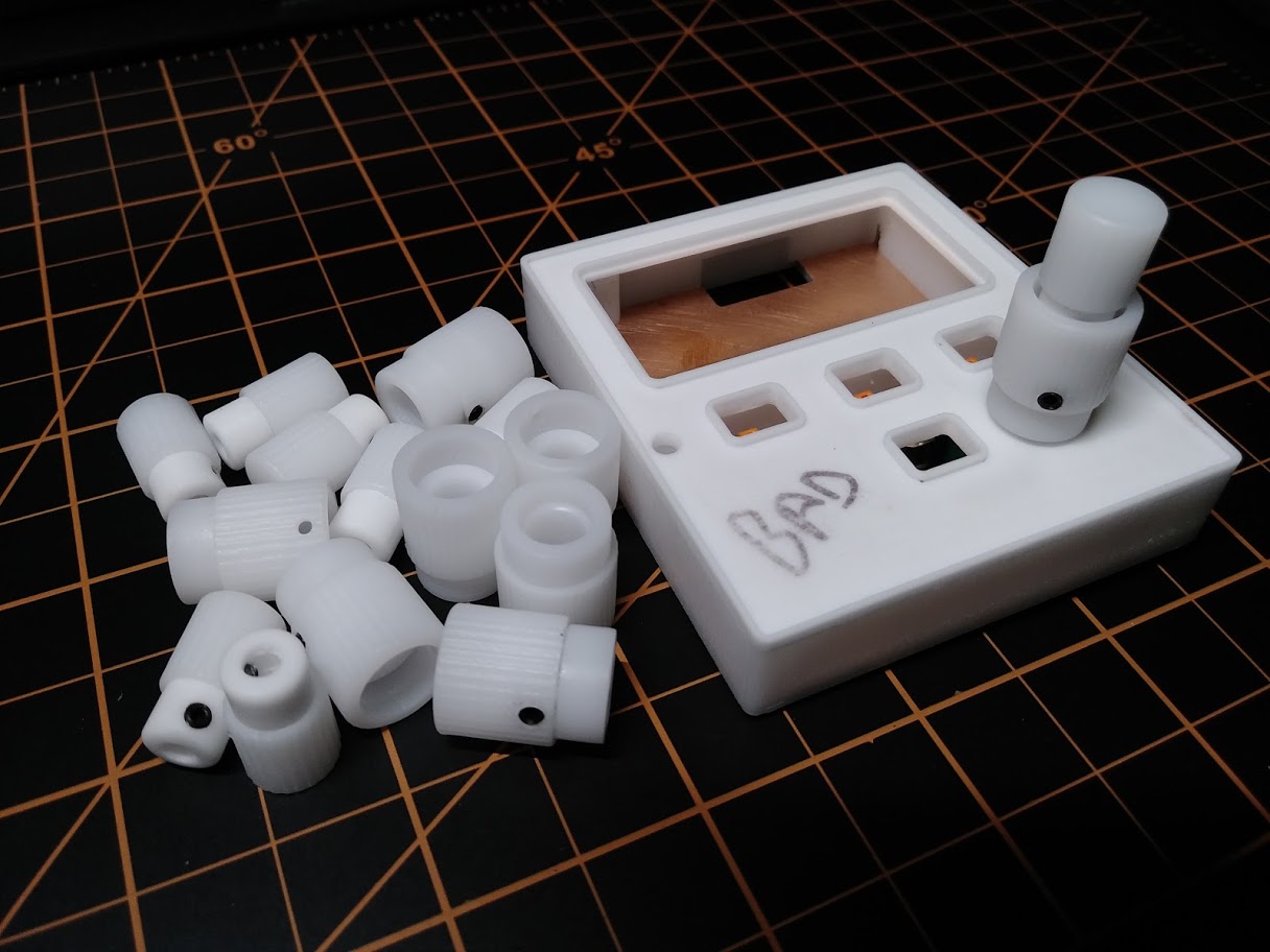
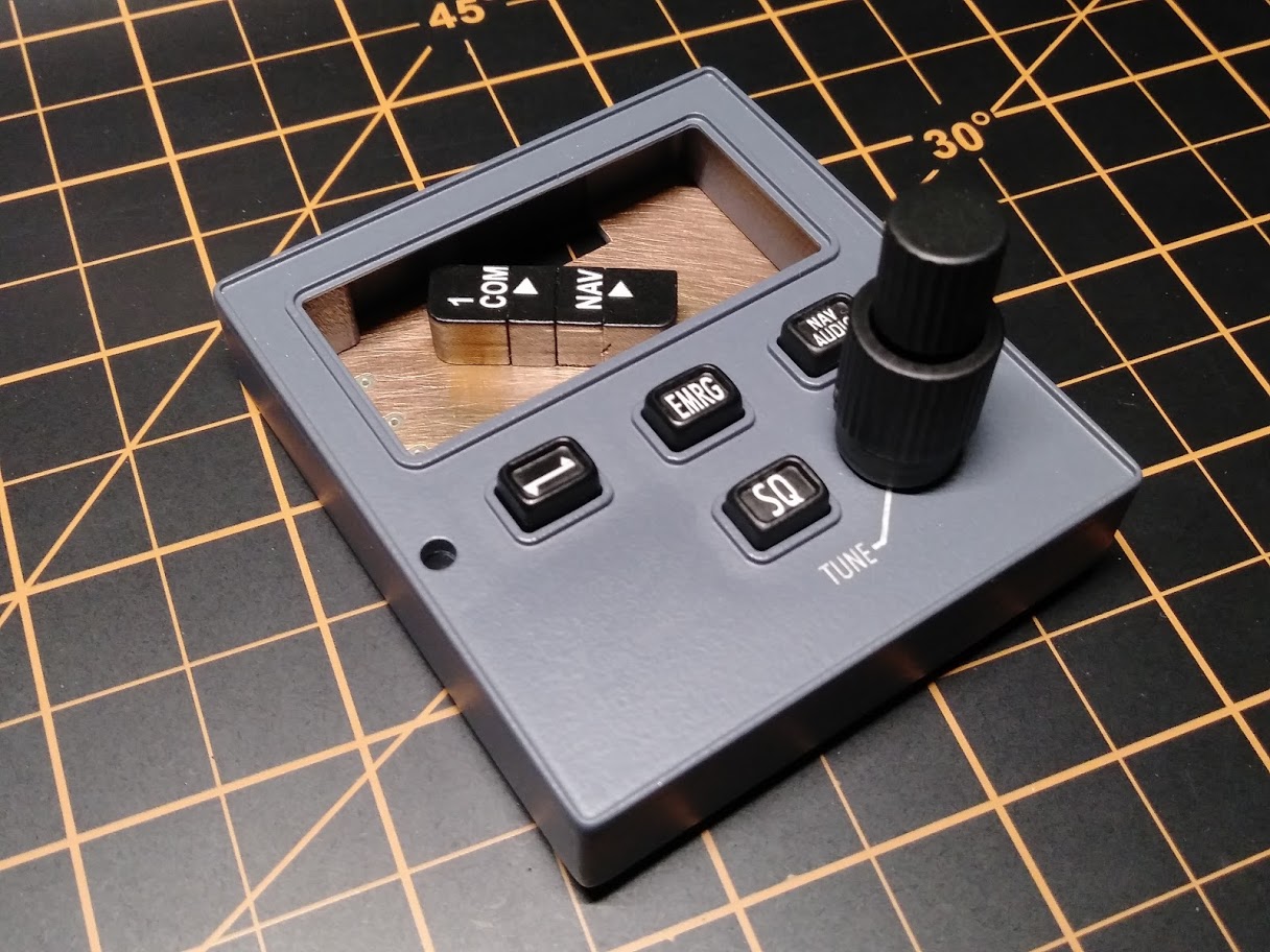
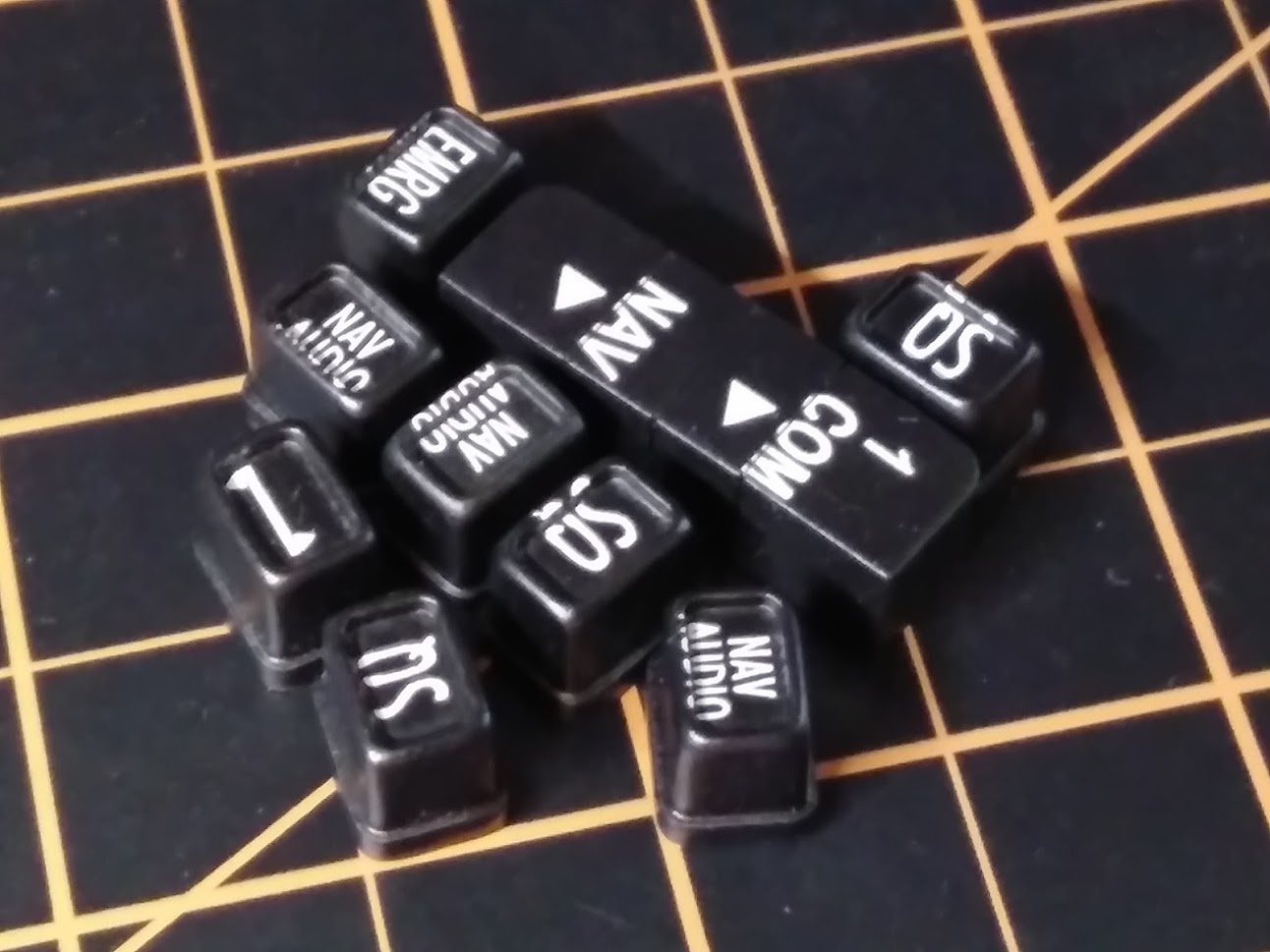
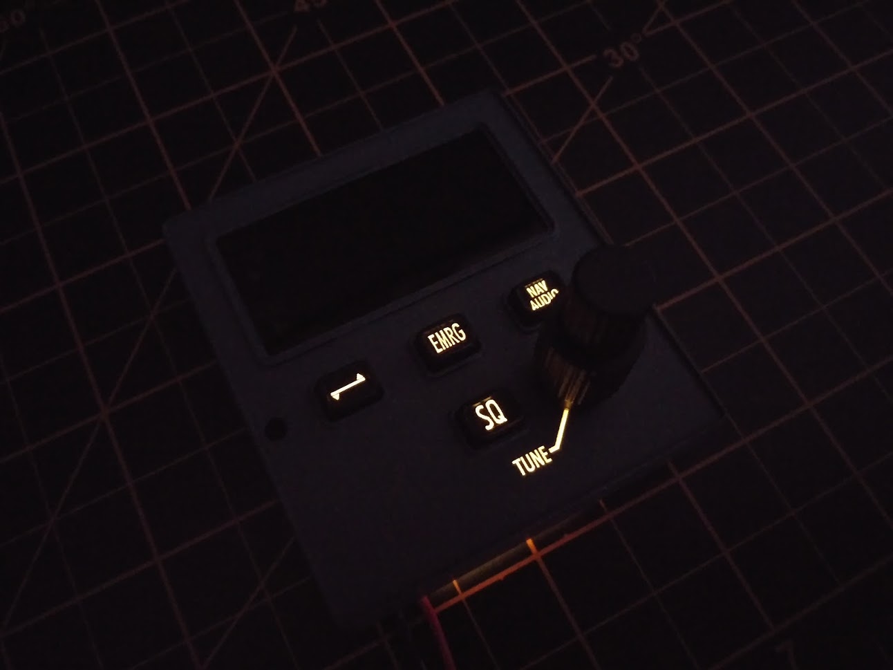
(Original thread started on 07-26-13 by Eric Tomlin) Very soon you will be able to order your very own Learjet 45 style Clearance Delivery Radio. Made in cooperation with Ruscool Electronics Ltd., these units will bring an operational radio to your simulator! • Learjet 45-style CDR offers realistic COM1 and NAV1 tuning capabilities in FS9, FSX and P3D • Laser engraved front panel and button set • Smoke-gray window • Dual Rotary Encoder with Dual Knob set • USB Plug and Play unit with remote mounted Radio Controller Board and panel-mount CDR Display unit Pricing is expected to be $330 Plus S&H. More details to follow soon: (Posted by Ron Rollo on 07-26-13) Thank you Eric for seeing this part of our project through. I am proud to say that I am one of the first to have received one and I really could not be happier with the end results. Here are a few photos of my CDR installed and working in my simulator: I used the dual encoder knobs that I got from Vince which worked very well. The other thing that I would recommend to anyone looking to get one of these is to use the darkest window tint you can find to tone down the light coming from the seven segment displays. This is a very easy thing to do: This is a photo of the PCB board and the many ribbon cables running to the back side: This is the sub panel with all the chips that hold the magic! Notice the two black wires coming out of the left side of the board? These are cut off lines that I have running to my FDS relay card. This enables us to simulate cutting off the power to the CDR with the RADIO CTRL HOT BUS switch on the SYS Test panel: Close up view of the CDR sub panel: Great job to Ruscool and Eric Tomlin! (Posted by Alan Norris on 07-27-13) I was wondering why the NAV function as my understanding of the CDR was so you could talk to ATC to get clearance prior to powering up the cockpit. I suspect it's incorporated as a backup. Those LEDs are bright! It's good that the smoked Plexiglas tones them down some. (Posted by Ron Rollo on 07-27-13) On top of the smoked Plexiglass, I used window tint to tone them down even further to a very comfortable level suited for night flight environment. Go to a window tinting shop and ask for a small piece of the darkest tint that they have. They will most likely give it to you with no charge. (Posted by Alan Norris on 07-28-13) I guess I should have looked as the training manual says that tuning the NAV frequency on the CDR is the same as tuning with the NAV frequency on RMU1. So it's a backup to RMU 1 as you mentioned. Does JET45 change the frequency on RMU 1 when it's tuned on the CDR and vice versa -- which I think it's supposed to do? I would think that tuning on the CDR would change the active frequency on RMU 1 as there is no transfer function on the CDR. (Posted by Eric Tomlin on 07-28-13) Hi Alan, the CDR's tuning will update both NAV1/COM 1 on the RMUs. However right now we are updating the JET45 code to work with a second hardware source to reflect the changes when input via the CDR. More on this soon. Here are some photos provided by Shane Barnes of the real CDR and the dual rotary encoder knob: The top knob fits down inside the lower knob. The overall heights is 1.090 inches. Notice the hole near the top of the bottom knob to allow access to the set screw that holds the top knob on? The top knob also has a recessed area in the top of the knob. (Posted by Ron Rollo on 08-05-13) I got the two LEDs that run the NAV and COM indicators working. NAV selected in this photo: COM selected in this photo: (Posted by Alan Norris on 08-05-13) I assume that you set the COM_write_to_Sim to 0 in the .ini file to get this to work. Do you have any problem tuning NAV or COM such as not being able to get to the exact frequency because the number keep jiggling? I had that issue that was fixed with setting the COM_write_to_Sim to 1. (Posted by Ron Rollo on 04-19-14) Hey Alan, the issue I was having is that it would either not work at all or it works perfectly. I did not see what your experiencing. I would have to double check to tell you what I currently have them set to. Looks like I might be one of the only guys that has a CDR running. It is an amazing little piece of work and it works great and as advertised. I do not yet have my RMUs hooked up (that will change in a few weeks) so I have not noticed any conflicts with Jet45. As for how it works, take a look at the last photos in this thread. You will see in this photo the CDR sub panel module that I have mounted on the avionics wall. All those ribbon cables go to the CDR panel in the cockpit. From the sub panel module a USB cable runs to the computer. To me it is kinda complicated but I can see why all this is needed. Maybe a guy like Eric G. would know of a way to make the CDR work in the same type of manor as the pressurization screen that he did such a wonder job on. As for me, it is beyond my pay grade so to speak! (Posted by Eric Tomlin on 04-22-14) Several people have taken delivery of these panels and they work fine. However, there was a minor mod made in the JET45 software that allowed better cooperation between the radios displayed in the RMU window(s) and the CDR displays. As for price and availability, I took orders for these long ago and they were a limited run. Ruscool still has 1-2 left on the shelf and can make more as can I (and in fact I have a few of the bodies left for some other folks). The price is listed on the first post of this thread. They are not listed at my site because everything has not been moved from the old site to the new (hence why there is no LJ45 stuff showing right now). It's a very long and tedious process and considering that the mass of folks wanting LJ45 product contacts me anyhow, it's not been a priority of getting it moved over to the new site as new orders have slowed way down over the past year. (Original thread started on 07-26-13 by Eric Tomlin) Very soon you will be able to order your very own Learjet 45 style Clearance Delivery Radio. Made in cooperation with Ruscool Electronics Ltd., these units will bring an operational radio to your simulator! • Learjet 45-style CDR offers realistic COM1 and NAV1 tuning capabilities in FS9, FSX and P3D • Laser engraved front panel and button set • Smoke-gray window • Dual Rotary Encoder with Dual Knob set • USB Plug and Play unit with remote mounted Radio Controller Board and panel-mount CDR Display unit Pricing is expected to be $330 Plus S&H. More details to follow soon: (Posted by Ron Rollo on 07-26-13) Thank you Eric for seeing this part of our project through. I am proud to say that I am one of the first to have received one and I really could not be happier with the end results. Here are a few photos of my CDR installed and working in my simulator: I used the dual encoder knobs that I got from Vince which worked very well. The other thing that I would recommend to anyone looking to get one of these is to use the darkest window tint you can find to tone down the light coming from the seven segment displays. This is a very easy thing to do: This is a photo of the PCB board and the many ribbon cables running to the back side: This is the sub panel with all the chips that hold the magic! Notice the two black wires coming out of the left side of the board? These are cut off lines that I have running to my FDS relay card. This enables us to simulate cutting off the power to the CDR with the RADIO CTRL HOT BUS switch on the SYS Test panel: Close up view of the CDR sub panel: Great job to Ruscool and Eric Tomlin! (Posted by Alan Norris on 07-27-13) I was wondering why the NAV function as my understanding of the CDR was so you could talk to ATC to get clearance prior to powering up the cockpit. I suspect it's incorporated as a backup. Those LEDs are bright! It's good that the smoked Plexiglas tones them down some. (Posted by Ron Rollo on 07-27-13) On top of the smoked Plexiglass, I used window tint to tone them down even further to a very comfortable level suited for night flight environment. Go to a window tinting shop and ask for a small piece of the darkest tint that they have. They will most likely give it to you with no charge. (Posted by Alan Norris on 07-28-13) I guess I should have looked as the training manual says that tuning the NAV frequency on the CDR is the same as tuning with the NAV frequency on RMU1. So it's a backup to RMU 1 as you mentioned. Does JET45 change the frequency on RMU 1 when it's tuned on the CDR and vice versa -- which I think it's supposed to do? I would think that tuning on the CDR would change the active frequency on RMU 1 as there is no transfer function on the CDR. (Posted by Eric Tomlin on 07-28-13) Hi Alan, the CDR's tuning will update both NAV1/COM 1 on the RMUs. However right now we are updating the JET45 code to work with a second hardware source to reflect the changes when input via the CDR. More on this soon. Here are some photos provided by Shane Barnes of the real CDR and the dual rotary encoder knob: The top knob fits down inside the lower knob. The overall heights is 1.090 inches. Notice the hole near the top of the bottom knob to allow access to the set screw that holds the top knob on? The top knob also has a recessed area in the top of the knob. (Posted by Ron Rollo on 08-05-13) I got the two LEDs that run the NAV and COM indicators working. NAV selected in this photo: COM selected in this photo: (Posted by Alan Norris on 08-05-13) I assume that you set the COM_write_to_Sim to 0 in the .ini file to get this to work. Do you have any problem tuning NAV or COM such as not being able to get to the exact frequency because the number keep jiggling? I had that issue that was fixed with setting the COM_write_to_Sim to 1. (Posted by Ron Rollo on 04-19-14) Hey Alan, the issue I was having is that it would either not work at all or it works perfectly. I did not see what your experiencing. I would have to double check to tell you what I currently have them set to. Looks like I might be one of the only guys that has a CDR running. It is an amazing little piece of work and it works great and as advertised. I do not yet have my RMUs hooked up (that will change in a few weeks) so I have not noticed any conflicts with Jet45. As for how it works, take a look at the last photos in this thread. You will see in this photo the CDR sub panel module that I have mounted on the avionics wall. All those ribbon cables go to the CDR panel in the cockpit. From the sub panel module a USB cable runs to the computer. To me it is kinda complicated but I can see why all this is needed. Maybe a guy like Eric G. would know of a way to make the CDR work in the same type of manor as the pressurization screen that he did such a wonder job on. As for me, it is beyond my pay grade so to speak! (Posted by Eric Tomlin on 04-22-14) Several people have taken delivery of these panels and they work fine. However, there was a minor mod made in the JET45 software that allowed better cooperation between the radios displayed in the RMU window(s) and the CDR displays. As for price and availability, I took orders for these long ago and they were a limited run. Ruscool still has 1-2 left on the shelf and can make more as can I (and in fact I have a few of the bodies left for some other folks). The price is listed on the first post of this thread. They are not listed at my site because everything has not been moved from the old site to the new (hence why there is no LJ45 stuff showing right now). It's a very long and tedious process and considering that the mass of folks wanting LJ45 product contacts me anyhow, it's not been a priority of getting it moved over to the new site as new orders have slowed way down over the past year. It has been a long time in the works but I can finally say that the new CDR / CDH v2.0, (Clearance Delivery Radio or Clearance Delivery Head) is in development and on the way. Here is a quick glance at the CDR v2.0 Master dxf drawing: (Right click to view) And here is a little CDR tease! As with all my panels, once the CDR is proven, the dxf and other associated files will be available here in the hangar for others to build if they choose. The CDR will also be available on the HANGAR PRODUCTS page. The new CDR is modeled after the Honeywell CD-850 which is found in all Lear40/45 aircraft. This new version has been designed to work exclusively with the new Jet45 AAS v2.0 software that is coming out. In addition to full plug and play compatibility with the new software, the new CDR is significantly improved over the Ruscool version while at the same time greatly simplified. The new CDR only has two plugs (three if you wanna count the 5volt backlighting plug) and both will get plugged directly into the RMU1/CDR Module. In this case, plug C and the CDR OLED plug. That's it! The other two plugs on the RMU1/CDR Module are for the pilot's side RMU1. If you are familiar with the Ruscool CDR, it's clear to see how much easier this new CDR setup will be. This is not a knock on Ruscool, their products are second to none and the CDR they developed was perfect for our Lear45 sims at the time. However, in an effort to move forward and to be fully compatible with the new Jet45 software, a new CDR design was needed. The new v2.0 CDR is going to use a 1.54" OLED display rather than the oversized seven segment displays. The only remote CON to this plan is that the crispness of the digits may not be as sharp as the seven segment display version but I do not think this will be an issue. Take a look at the close up of the 1.54 OLED screen below keeping in mind that the main frequency font lines will be twice as large as what you see here. Additionally, the OLED displays allow us to view the display from all extreme angles, unlike a typical LCD or LED screen! (Right click to take a closer look at the pixels) Here is a short list of enhancements over the Ruscool CDR version: Several of the listed enhancements will be available to us and can be modeled if we find value in them where none of this was possible with the old Ruscool design. The final features list will be determined later but as you can see, we are planing to make all options possible within the physical part of the CDR design. I have only just started with a small batch of six CDR prototypes. So far I have the front face which is front and rear milled and will be later glued to a CDR body which will give the CDR it's overall thickness which is close to .5" The hardest part of the new CDR design process was finding a suitable display. It had to be small enough to fit in the CDR while at the same time not so big that it interfered with other components. My first choice was the proper size seven segment displays, but none suited. The real CDR uses a dichroic transreflective LCD display but finding a manufacturer to make such a small number makes this option nearly impossible. Typical LCD screens readily available were too large and even if they were the perfect fit, I have found that the viewing angle would have been an issue. If you have been paying attention, the answer is 1.54" OLED "white"displays! (There may be a quiz at the end of this update) But even the PCB tabs were too big for the space they needed to fit into if I wanted to keep the scale 100%. This is another case of putting a part on a diet. I had to trim off the bottom two mounting tabs built into the pcb board. As best as I can tell, front and back, there are no trace lines running through these areas. If there are center layers built into the pcb and trace lines meandering in these areas, back to the drawing board we go. But chances of that are less than 1%. To end this update, the CDR is a small piece of the Lear45 sim puzzle, but an important one. It is also one of the last bits of the planning puzzle needing to be put in place to properly test the new Jet45 AAS software! Therefore, the CDRs are on high priority until they are complete. Another update soon! It has been a long time in the works but I can finally say that the new CDR / CDH v2.0, (Clearance Delivery Radio or Clearance Delivery Head) is in development and on the way. Here is a quick glance at the CDR v2.0 Master dxf drawing: (Right click to view) And here is a little CDR tease! As with all my panels, once the CDR is proven, the dxf and other associated files will be available here in the hangar for others to build if they choose. The CDR will also be available on the HANGAR PRODUCTS page. The new CDR is modeled after the Honeywell CD-850 which is found in all Lear40/45 aircraft. This new version has been designed to work exclusively with the new Jet45 AAS v2.0 software that is coming out. In addition to full plug and play compatibility with the new software, the new CDR is significantly improved over the Ruscool version while at the same time greatly simplified. The new CDR only has two plugs (three if you wanna count the 5volt backlighting plug) and both will get plugged directly into the RMU1/CDR Module. In this case, plug C and the CDR OLED plug. That's it! The other two plugs on the RMU1/CDR Module are for the pilot's side RMU1. If you are familiar with the Ruscool CDR, it's clear to see how much easier this new CDR setup will be. This is not a knock on Ruscool, their products are second to none and the CDR they developed was perfect for our Lear45 sims at the time. However, in an effort to move forward and to be fully compatible with the new Jet45 software, a new CDR design was needed. The new v2.0 CDR is going to use a 1.54" OLED display rather than the oversized seven segment displays. The only remote CON to this plan is that the crispness of the digits may not be as sharp as the seven segment display version but I do not think this will be an issue. Take a look at the close up of the 1.54 OLED screen below keeping in mind that the main frequency font lines will be twice as large as what you see here. Additionally, the OLED displays allow us to view the display from all extreme angles, unlike a typical LCD or LED screen! (Right click to take a closer look at the pixels) Here is a short list of enhancements over the Ruscool CDR version: Several of the listed enhancements will be available to us and can be modeled if we find value in them where none of this was possible with the old Ruscool design. The final features list will be determined later but as you can see, we are planing to make all options possible within the physical part of the CDR design. I have only just started with a small batch of six CDR prototypes. So far I have the front face which is front and rear milled and will be later glued to a CDR body which will give the CDR it's overall thickness which is close to .5" The hardest part of the new CDR design process was finding a suitable display. It had to be small enough to fit in the CDR while at the same time not so big that it interfered with other components. My first choice was the proper size seven segment displays, but none suited. The real CDR uses a dichroic transreflective LCD display but finding a manufacturer to make such a small number makes this option nearly impossible. Typical LCD screens readily available were too large and even if they were the perfect fit, I have found that the viewing angle would have been an issue. If you have been paying attention, the answer is 1.54" OLED "white"displays! (There may be a quiz at the end of this update) But even the PCB tabs were too big for the space they needed to fit into if I wanted to keep the scale 100%. This is another case of putting a part on a diet. I had to trim off the bottom two mounting tabs built into the pcb board. As best as I can tell, front and back, there are no trace lines running through these areas. If there are center layers built into the pcb and trace lines meandering in these areas, back to the drawing board we go. But chances of that are less than 1%. To end this update, the CDR is a small piece of the Lear45 sim puzzle, but an important one. It is also one of the last bits of the planning puzzle needing to be put in place to properly test the new Jet45 AAS software! Therefore, the CDRs are on high priority until they are complete. Another update soon! Part 2 of the CDR v2.0 development! A lot of progress has been made over the past two weeks including learning about the finer points of the CDR. Thanks to DonnyRay for doing some deep research on this subject, we now have a full understanding of the operation and the history of the CDR found in the Lear40/45 and why certain things are the way they are. Here are some of the highlights: You may have noticed that some photos of the Lear40/45 have a CDR that also includes a MODE knob to the left of the dual encoder knobs and only has three small push buttons. This was the original CDR called the CD-850 7513000-807. This version only had five digits in the COM frequency line which only allowed for 25 KHz spacing and was becoming a problem in Europe. (Europe was quickly running out of frequency channels and needed tighter channel spacing.) In the year 2000, SB 45-23-3 (Lear45 Service Bulletin) recommended replacing all 7513000-807s with the newer 7513000-835s regardless of the airframe serial number. This is the CDR that does not include the MODE knob and has four small push buttons. This is also the CDR that I am currently modeling. One of the most notable changes besides dropping the MODE knob for a single EMER button is the addition of the sixth digit in the COM frequency line. This new version can tune both 25 and 8.33 KHz spacing increases freq options by three fold which resolves the lack of COM channels over in Europe. And now you know! Moving onto the CDR v2.0 updates! First, I need to start with the CDR main bodies. These will be cemented to the CDR face plates making them one part. This is the piece that gives the CDRs the nearly half inch thickness. (The actual thickness of the CDR is .485") Also note that each CDR main body has six brass inserts. The four corners are for the 2-56 screws that hold the double sided clad in place and the two middle ones are for the 4-40 screws that hold the CDR to the System Test Panel Backer. Here is the double sided clad. I am using .06" thick clad for extra strength due to the dual encoder. The obverse side of the clad handles the back lighting circuit while the reverse takes care of the buttons, dual encoder and the LED indicator blocks to the left of the OLED screen. Also note the four countersinks in the corners for the 2-56 screws. This photo shows how the 1.54" OLED screen sits inside it's pocket. To the left of the OLED screen will be four LED indicator blocks. Nothing is soldered in place yet. The fit of the double sided clad in the back side socket of the CDR body is perfect. For you CNC guys, I found the easiest way to do this is to create the G-code using a 1/16" tool, however, actually use a 2mm tool to do the final outside cut. A 2mm tool = .07874015748" which is slightly larger than a 1/16" tool (.0625") Now it's getting fun! The buttons and LED indicator blocks. Because the buttons and the indicator blocks light up along with the word TUNE on the face of the CDR, the main part of these pieces need to be clear but the top face has to be #3015 cast white. The trick is to bond clear plastic with white. In a nut shell, you need to use SciGrip 16 FAST SET Clear Medium Bodied Solvent Cement for Acrylic. It's in the blue tube! You will also need a set of rollers to squeeze all the extra cement out from between the two pieces of plastic. After prepping the two pieces of plastic by sanding them with an orbital sander, I use a piece of tape to hold the two pieces of plastic together as if they are two book covers. You will also want to wrap the two parts in a large piece of construction paper to catch the extra glue because when it dries, whatever it is touching becomes part of it! Once you have everything set, squeeze a good amount of cement in the crease where the two pieces of plastic are taped together and roll it through the rollers. The results are almost instantaneous, but just to make sure the bond is solid, put the newly bonded part on the flattest surface you can find and weight it down for about an hour. The end result is you have just created a solid piece of plastic that has two properties! The photo below includes two pieces of exactly the same piece of newly created dual material plastic. Clear/White. The piece for the buttons on the left did not need any additional prep, however, the piece for the LED indicator blocks had to be painted flat white on the bottom side and the top white side also has to be knocked down .08". If you look very close, you will see about .o4" of white plastic on the top followed by what looks like frost which is actually clear. The flat white paint on the very bottom makes the piece look frosty while the button stock looks clear. This is a great illustration as to why we have to make sure all parts inside the light chambers of all our panels have to be white so that the light color looks good. The CNC and the G-Code does all the heavy lifting although there is still plenty of hand sanding to do. Here are enough buttons for eight sets. I am making two extra sets just in case the laser shop screws up a set or two during setup, which when you are working with things this small, it is expected. More on that later. The LED indicator blocks are made slightly different. Because I have to cut a LED socket in the back side, I had to first knock the top white down so that it was only .04" thick. This is about the thickness you need to be at so that light can pass through and look great. If you look closely, you can see the top white plastic which is .04" thick and the rest is clear. The back side is painted flat white to keep the light inside the LED blocks. The next step will be to paint them flat white so that the light is bouncing off of white walls inside the LED blocks. Then paint them black so that they can be laser engraved. This is a lot of work but well worth the effort! To recap, this is where we are at this point! 90% of all parts are cut and sanded. I still need to make the encoder knobs, internal light plate and paint plugs. This next photo includes the old Ruscool CDR on the left and the new Project45 CDR v2.0 on the right. For us guys who have a Ruscool CDR, we will really be able to appreciate the effort put into the scale of the new CDR v2.0. It is only when they are side by side that the scaling issues are apparent. At this point the CDR is about 60% complete. This next week will be all about getting parts ready for laser engraving. Another update soon! Part 2 of the CDR v2.0 development! A lot of progress has been made over the past two weeks including learning about the finer points of the CDR. Thanks to DonnyRay for doing some deep research on this subject, we now have a full understanding of the operation and the history of the CDR found in the Lear40/45 and why certain things are the way they are. Here are some of the highlights: You may have noticed that some photos of the Lear40/45 have a CDR that also includes a MODE knob to the left of the dual encoder knobs and only has three small push buttons. This was the original CDR called the CD-850 7513000-807. This version only had five digits in the COM frequency line which only allowed for 25 KHz spacing and was becoming a problem in Europe. (Europe was quickly running out of frequency channels and needed tighter channel spacing.) In the year 2000, SB 45-23-3 (Lear45 Service Bulletin) recommended replacing all 7513000-807s with the newer 7513000-835s regardless of the airframe serial number. This is the CDR that does not include the MODE knob and has four small push buttons. This is also the CDR that I am currently modeling. One of the most notable changes besides dropping the MODE knob for a single EMER button is the addition of the sixth digit in the COM frequency line. This new version can tune both 25 and 8.33 KHz spacing increases freq options by three fold which resolves the lack of COM channels over in Europe. And now you know! Moving onto the CDR v2.0 updates! First, I need to start with the CDR main bodies. These will be cemented to the CDR face plates making them one part. This is the piece that gives the CDRs the nearly half inch thickness. (The actual thickness of the CDR is .485") Also note that each CDR main body has six brass inserts. The four corners are for the 2-56 screws that hold the double sided clad in place and the two middle ones are for the 4-40 screws that hold the CDR to the System Test Panel Backer. Here is the double sided clad. I am using .06" thick clad for extra strength due to the dual encoder. The obverse side of the clad handles the back lighting circuit while the reverse takes care of the buttons, dual encoder and the LED indicator blocks to the left of the OLED screen. Also note the four countersinks in the corners for the 2-56 screws. This photo shows how the 1.54" OLED screen sits inside it's pocket. To the left of the OLED screen will be four LED indicator blocks. Nothing is soldered in place yet. The fit of the double sided clad in the back side socket of the CDR body is perfect. For you CNC guys, I found the easiest way to do this is to create the G-code using a 1/16" tool, however, actually use a 2mm tool to do the final outside cut. A 2mm tool = .07874015748" which is slightly larger than a 1/16" tool (.0625") Now it's getting fun! The buttons and LED indicator blocks. Because the buttons and the indicator blocks light up along with the word TUNE on the face of the CDR, the main part of these pieces need to be clear but the top face has to be #3015 cast white. The trick is to bond clear plastic with white. In a nut shell, you need to use SciGrip 16 FAST SET Clear Medium Bodied Solvent Cement for Acrylic. It's in the blue tube! You will also need a set of rollers to squeeze all the extra cement out from between the two pieces of plastic. After prepping the two pieces of plastic by sanding them with an orbital sander, I use a piece of tape to hold the two pieces of plastic together as if they are two book covers. You will also want to wrap the two parts in a large piece of construction paper to catch the extra glue because when it dries, whatever it is touching becomes part of it! Once you have everything set, squeeze a good amount of cement in the crease where the two pieces of plastic are taped together and roll it through the rollers. The results are almost instantaneous, but just to make sure the bond is solid, put the newly bonded part on the flattest surface you can find and weight it down for about an hour. The end result is you have just created a solid piece of plastic that has two properties! The photo below includes two pieces of exactly the same piece of newly created dual material plastic. Clear/White. The piece for the buttons on the left did not need any additional prep, however, the piece for the LED indicator blocks had to be painted flat white on the bottom side and the top white side also has to be knocked down .08". If you look very close, you will see about .o4" of white plastic on the top followed by what looks like frost which is actually clear. The flat white paint on the very bottom makes the piece look frosty while the button stock looks clear. This is a great illustration as to why we have to make sure all parts inside the light chambers of all our panels have to be white so that the light color looks good. The CNC and the G-Code does all the heavy lifting although there is still plenty of hand sanding to do. Here are enough buttons for eight sets. I am making two extra sets just in case the laser shop screws up a set or two during setup, which when you are working with things this small, it is expected. More on that later. The LED indicator blocks are made slightly different. Because I have to cut a LED socket in the back side, I had to first knock the top white down so that it was only .04" thick. This is about the thickness you need to be at so that light can pass through and look great. If you look closely, you can see the top white plastic which is .04" thick and the rest is clear. The back side is painted flat white to keep the light inside the LED blocks. The next step will be to paint them flat white so that the light is bouncing off of white walls inside the LED blocks. Then paint them black so that they can be laser engraved. This is a lot of work but well worth the effort! To recap, this is where we are at this point! 90% of all parts are cut and sanded. I still need to make the encoder knobs, internal light plate and paint plugs. This next photo includes the old Ruscool CDR on the left and the new Project45 CDR v2.0 on the right. For us guys who have a Ruscool CDR, we will really be able to appreciate the effort put into the scale of the new CDR v2.0. It is only when they are side by side that the scaling issues are apparent. At this point the CDR is about 60% complete. This next week will be all about getting parts ready for laser engraving. Another update soon! Part 3 of the CDR v2.0 development! All the CNC work is complete and 99% of the parts are sanded. (Very time consuming) Most of the painting is complete also. All the main CDR bodies, buttons and LED blocks have been dropped off at the laser shop for engraving! The big items still to be completed are soldering and final assembly. Here are some of the highlights of the CDR work done in the past weeks. First, let's start with the main CDR body paint. Like all my panels, I use a "paint plug" to create a clean pocket where I do not want paint. In the case of the CDR, I used .33" thick plastic where most panels only need .125" thick plastic. You might notice in the photo above some plastic filler along the sides to fill in some of the tool marks. In the photo below, paint is applied. Speaking of paint, we are now using Rust-Oleum Primer Gray for all panels and parts, see HERE After the paint dries, simply remove the plugs and you are left with a nice clean pocket! A closer look at the CDR main bodies ready for a little laser engraving. The CDR main body only requires the word "TUNE" with a indicator line pointing to the encoder. The next item completed is what I call the light plate. These parts are made with .25" thick clear plastic stock, sanded with an orbital sander on both sides and painted flat white on the back. In other words, you have to paint your .25" clear stock prior to engraving. Once your plastic stock is prepped, let the CNC do it's thing! The final step is adding aluminum tape on top of all the light points. This does two things, first, it stops hot spots in the front panel paint. Second, it reflects the light back into the light plate where it bounces off of the white paint and tiny scratches made with the orbital sander. This is called "light scattering". Without this light plate, the light from the LEDs does not spread out and fill the light pocket evenly. In the case of the CDR, we not only need to light up a little artwork engraved into the front of the CDR, but we also want to back light the buttons! (The real CDR uses EL backlighting which is not an option for us.) Speaking of buttons, here they are ready for some laser engraving. Also included in this photo is the LED blocks. Have you ever wondered how to laser engrave such small pieces? The answer is to create a register to hold the parts. The laser shop burns the outline file onto a piece of metal and then they simply line up the register onto that outline. (A little more to it but this is how the alignment is sorted) By the way, the LED blocks are all individually painted white, then painted black then glued together, then painted black with LED paint plugs! This is a lot of work but every step is necessary in order to keep the light from one LED block from bleeding into another. I am excited to see how this works out but won't know until the parts come back from the laser shop. Last but not least, the knobs. They really stand out! Thanks to DonnyRay for supplying me with some real knob data, I was able to design the best CDR knob replica possible for the encoder we are using. The results are the knobs are perfectly scaled and will appear to be exactly what you would expect to see on a real CDR. The only difference will be the placement of the set screw in the outer knob. In order to make these knobs, it requires both knobs to be made in two pieces. I picked up a couple more CNC skills including learning how to make a longer DOC bit and channeling out a cut before doing the knurling cut! Don't mind the "BAD" on the CDR. This was my first attempt but good enough to test fit other pieces. As you can see, the set screw in the outer knob is up in the knurled areas instead of the lower base. I bet if I had not mentioned this you would not have known the difference! Once painted and installed, they will look and operate perfectly. One more update in a couple weeks to finish out the CDRs, the physical part of the CDR anyway! Part 3 of the CDR v2.0 development! All the CNC work is complete and 99% of the parts are sanded. (Very time consuming) Most of the painting is complete also. All the main CDR bodies, buttons and LED blocks have been dropped off at the laser shop for engraving! The big items still to be completed are soldering and final assembly. Here are some of the highlights of the CDR work done in the past weeks. First, let's start with the main CDR body paint. Like all my panels, I use a "paint plug" to create a clean pocket where I do not want paint. In the case of the CDR, I used .33" thick plastic where most panels only need .125" thick plastic. You might notice in the photo above some plastic filler along the sides to fill in some of the tool marks. In the photo below, paint is applied. Speaking of paint, we are now using Rust-Oleum Primer Gray for all panels and parts, see HERE After the paint dries, simply remove the plugs and you are left with a nice clean pocket! A closer look at the CDR main bodies ready for a little laser engraving. The CDR main body only requires the word "TUNE" with a indicator line pointing to the encoder. The next item completed is what I call the light plate. These parts are made with .25" thick clear plastic stock, sanded with an orbital sander on both sides and painted flat white on the back. In other words, you have to paint your .25" clear stock prior to engraving. Once your plastic stock is prepped, let the CNC do it's thing! The final step is adding aluminum tape on top of all the light points. This does two things, first, it stops hot spots in the front panel paint. Second, it reflects the light back into the light plate where it bounces off of the white paint and tiny scratches made with the orbital sander. This is called "light scattering". Without this light plate, the light from the LEDs does not spread out and fill the light pocket evenly. In the case of the CDR, we not only need to light up a little artwork engraved into the front of the CDR, but we also want to back light the buttons! (The real CDR uses EL backlighting which is not an option for us.) Speaking of buttons, here they are ready for some laser engraving. Also included in this photo is the LED blocks. Have you ever wondered how to laser engrave such small pieces? The answer is to create a register to hold the parts. The laser shop burns the outline file onto a piece of metal and then they simply line up the register onto that outline. (A little more to it but this is how the alignment is sorted) By the way, the LED blocks are all individually painted white, then painted black then glued together, then painted black with LED paint plugs! This is a lot of work but every step is necessary in order to keep the light from one LED block from bleeding into another. I am excited to see how this works out but won't know until the parts come back from the laser shop. Last but not least, the knobs. They really stand out! Thanks to DonnyRay for supplying me with some real knob data, I was able to design the best CDR knob replica possible for the encoder we are using. The results are the knobs are perfectly scaled and will appear to be exactly what you would expect to see on a real CDR. The only difference will be the placement of the set screw in the outer knob. In order to make these knobs, it requires both knobs to be made in two pieces. I picked up a couple more CNC skills including learning how to make a longer DOC bit and channeling out a cut before doing the knurling cut! Don't mind the "BAD" on the CDR. This was my first attempt but good enough to test fit other pieces. As you can see, the set screw in the outer knob is up in the knurled areas instead of the lower base. I bet if I had not mentioned this you would not have known the difference! Once painted and installed, they will look and operate perfectly. One more update in a couple weeks to finish out the CDRs, the physical part of the CDR anyway! Here is the final update on the CDR, at least the physical parts of it! A couple weeks ago I picked up the front panels and buttons form the laser shop. All good for the most part. But there was an issue with the button alignment on a couple sets. I planned for this and made two extra sets in case of this scenario. The button and LED blocks in the photo below unfortunately have already made their way to the "rubbish" bin! I was able to get five clean and properly aligned sets. The back lighting came out perfectly. In the photo below, I am not using a light plate and it is debatable if one is even needed in this panel. I opted to use them anyway because the bottom side is painted white and will help reflect the warm white LED light back up and into the panel. Otherwise, the light is bouncing off the copper clad. The biggest reason I opted to use them is in case anyone wants or needs to adjust the color of the light using paper filters. I do not plan to use filters but it is an option we have if you need it. The LED blocks were the most challenging part of the CDR. The key to making this work is controlling 100% of the light from bleeding into the other LED blocks. The photo above shows the COM indicator arrow pointing to the COM freq. The photo below shows the NAV indicator arrow pointing to the NAV freq. The area to the right is where the OLED screen is going to display those frequencies along with some additional info. Here is a snap shot of the inside of the CDR where you can see just how tight everything is. The buttons in the lower light chamber have black paper bezels to help control 99% of light bleed. And here is the backside. In this photo I already have the CDR wired up and ready for testing. You can see the five pin plug socket to the right for the OLED screen. Here is the completed CDR prototype! (Production models will not include the "Honeywell" decal.) This CDR prototype is being sent out to Jason so he can work his magic to bring it to life! I wanted to take a minute to post up what we can expect from the CDR. For the most part, it will operate just like the real one works in the Lear45. You can refer to you manuals! CDR/CDH operation in a nut shell: The CDR has two modes of operation. Normal and Emergency. You can toggle between these two modes with the EMRG button. Here is the final update on the CDR, at least the physical parts of it! A couple weeks ago I picked up the front panels and buttons form the laser shop. All good for the most part. But there was an issue with the button alignment on a couple sets. I planned for this and made two extra sets in case of this scenario. The button and LED blocks in the photo below unfortunately have already made their way to the "rubbish" bin! I was able to get five clean and properly aligned sets. The back lighting came out perfectly. In the photo below, I am not using a light plate and it is debatable if one is even needed in this panel. I opted to use them anyway because the bottom side is painted white and will help reflect the warm white LED light back up and into the panel. Otherwise, the light is bouncing off the copper clad. The biggest reason I opted to use them is in case anyone wants or needs to adjust the color of the light using paper filters. I do not plan to use filters but it is an option we have if you need it. The LED blocks were the most challenging part of the CDR. The key to making this work is controlling 100% of the light from bleeding into the other LED blocks. The photo above shows the COM indicator arrow pointing to the COM freq. The photo below shows the NAV indicator arrow pointing to the NAV freq. The area to the right is where the OLED screen is going to display those frequencies along with some additional info. Here is a snap shot of the inside of the CDR where you can see just how tight everything is. The buttons in the lower light chamber have black paper bezels to help control 99% of light bleed. And here is the backside. In this photo I already have the CDR wired up and ready for testing. You can see the five pin plug socket to the right for the OLED screen. Here is the completed CDR prototype! (Production models will not include the "Honeywell" decal.) This CDR prototype is being sent out to Jason so he can work his magic to bring it to life! I wanted to take a minute to post up what we can expect from the CDR. For the most part, it will operate just like the real one works in the Lear45. You can refer to you manuals! CDR/CDH operation in a nut shell: The CDR has two modes of operation. Normal and Emergency. You can toggle between these two modes with the EMRG button. Looking very neat Ron!! Looking very neat Ron!! Ron, I have to say as an owner of the previous Ruscool Clearance Delivery Radio, your updated version, with Jason's help, is exemplary. I have been waiting for many years for the link to alter a setting on the CDR and it updates on the RMU. Can't wait to get my hands on this little beauty AND I CAN CONFIRM that you will use it even for normal COM and Nav frequencies, because my flight crew and I did regularly. Hit me with it....now ! Mark S. Ron, I have to say as an owner of the previous Ruscool Clearance Delivery Radio, your updated version, with Jason's help, is exemplary. I have been waiting for many years for the link to alter a setting on the CDR and it updates on the RMU. Can't wait to get my hands on this little beauty AND I CAN CONFIRM that you will use it even for normal COM and Nav frequencies, because my flight crew and I did regularly. Hit me with it....now ! Mark S. Thanks guys, Jason received the CDR prototype last week (USPS delivered a couple days early for some reason) and within just a couple hours, he had the screen preprogrammed with ALL the text! This thing is going to be amazing once Jason get done with it. It goes without saying that the work I have put into this does not amount to a hill of beans without Jason's amazing talents! One thing I was just a tad concerned about was where I had to trim the bottom of the OLED PCB to make it fit within the CDR in order to keep things to scale. Turns out, nothing to worry about there. We did hit one small hiccup and that was Jason had an earlier RMU1/CDR module that was not up to date. I have since made an updated one for him and it should arrive by Tuesday. Once he gets his hands on the updated module, we can expect to see an update from him! I am working on your CDR as I type Mark. Yours and five others! You are going to love the improvements over the Ruscool design! As soon as I get the okay from Jason, I will be shipping one off to you. Thanks guys, Jason received the CDR prototype last week (USPS delivered a couple days early for some reason) and within just a couple hours, he had the screen preprogrammed with ALL the text! This thing is going to be amazing once Jason get done with it. It goes without saying that the work I have put into this does not amount to a hill of beans without Jason's amazing talents! One thing I was just a tad concerned about was where I had to trim the bottom of the OLED PCB to make it fit within the CDR in order to keep things to scale. Turns out, nothing to worry about there. We did hit one small hiccup and that was Jason had an earlier RMU1/CDR module that was not up to date. I have since made an updated one for him and it should arrive by Tuesday. Once he gets his hands on the updated module, we can expect to see an update from him! I am working on your CDR as I type Mark. Yours and five others! You are going to love the improvements over the Ruscool design! As soon as I get the okay from Jason, I will be shipping one off to you. Here's a sneak peak at the CDR in development. Ron has done an incredible job designing and packaging this little radio. More to come! Here's a sneak peak at the CDR in development. Ron has done an incredible job designing and packaging this little radio. More to come! Hey Jason, I am also, amongst other things working on de CDR. Don't look at weird lines on the photo, i have broken the oled :S Hey Jason, I am also, amongst other things working on de CDR. Don't look at weird lines on the photo, i have broken the oled :S CDR Developement and Setup
![]()

![]()
![]()

![]()
![]()
![]()
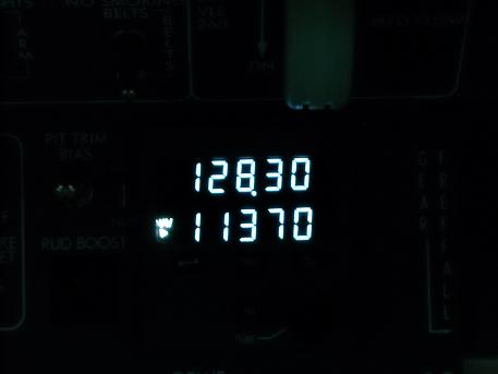
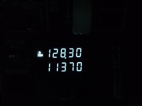
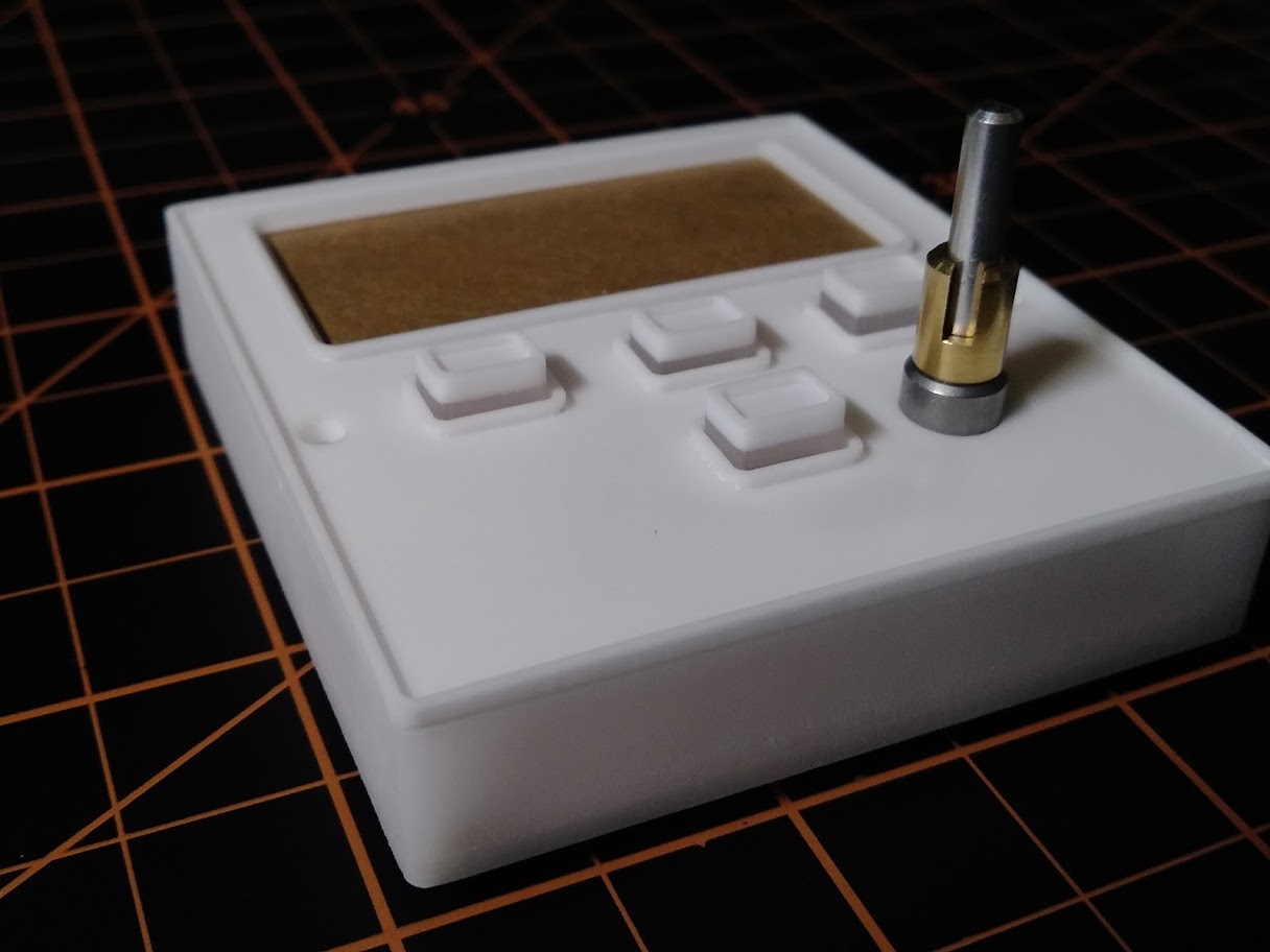
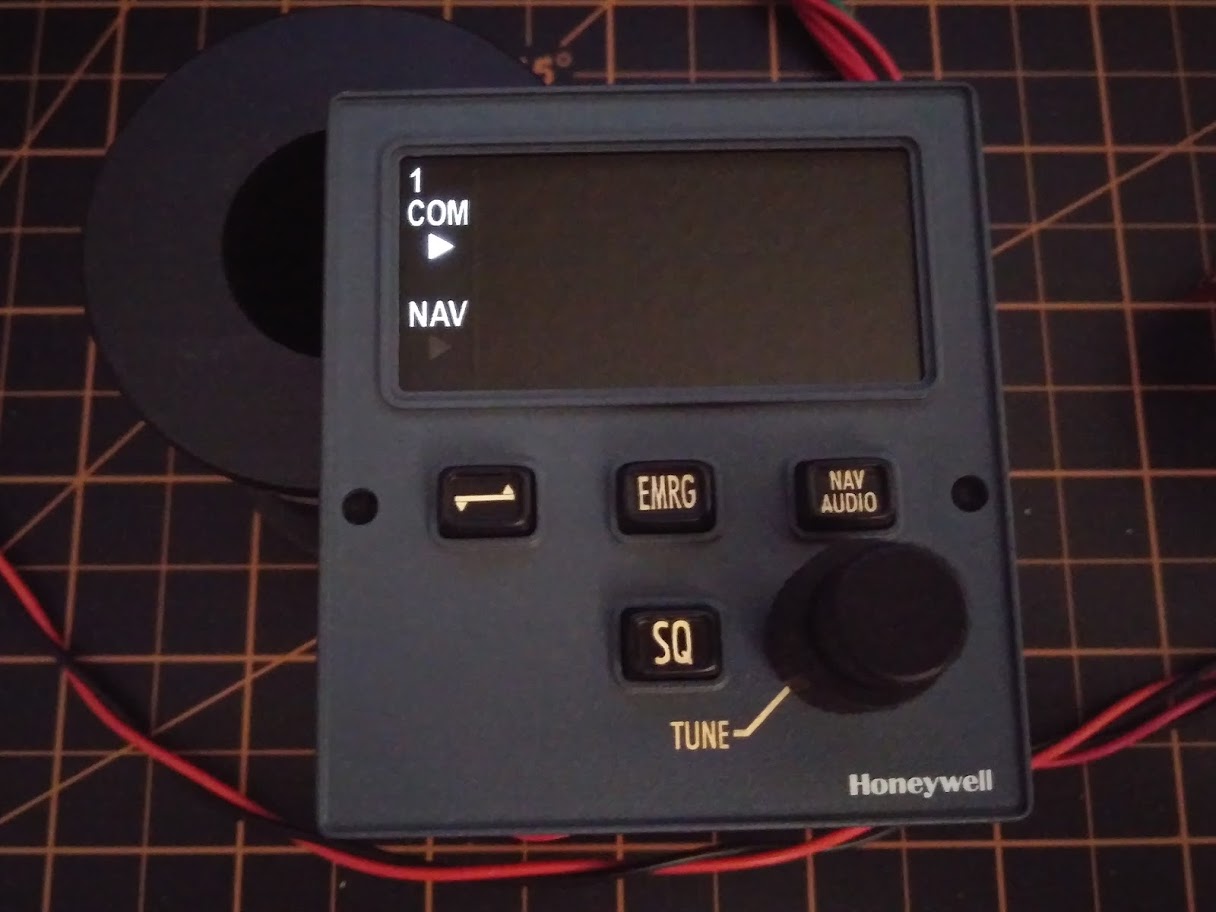
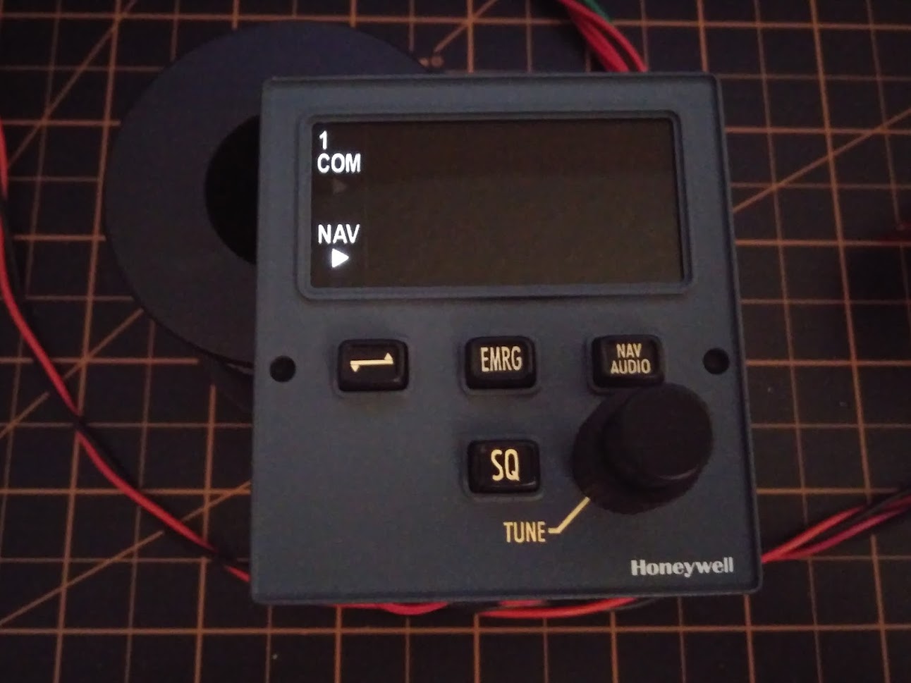
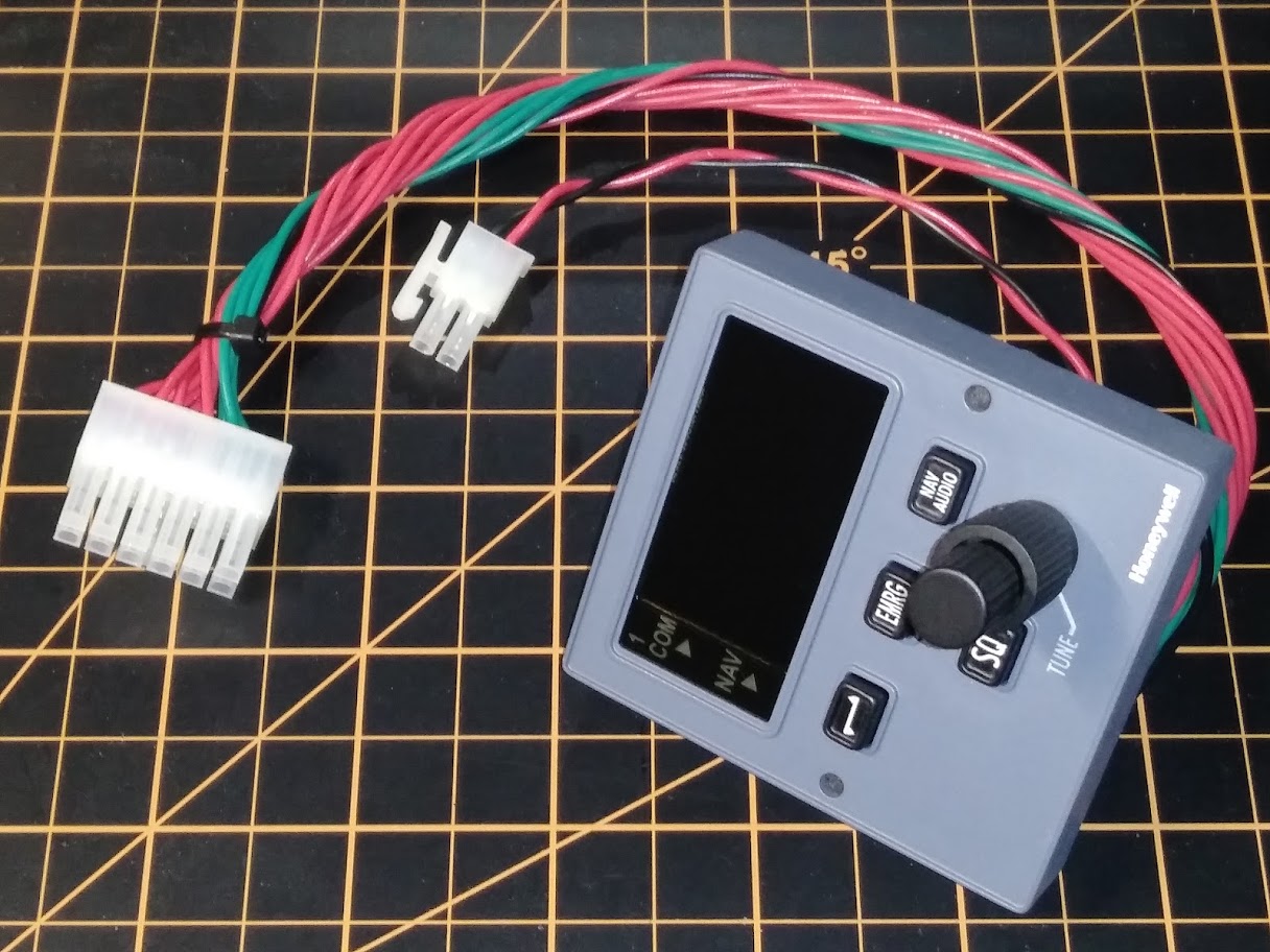
I still doubt if I will use the LED's , I display these things now as text on the OLED, which indeed is smaller then the housing, but when centered also looks ok.
I still doubt if I will use the LED's , I display these things now as text on the OLED, which indeed is smaller then the housing, but when centered also looks ok.![]()
![]()
![]()
![]()
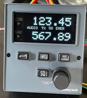
What i don't like on the OLED screens are the fonts, i see your font also looks a bit grainy. (if that's the correct english)
I have found an arduino adafuit font : DSEG7_Classic_Regular_16 which, at least shows the frequencies font smoother.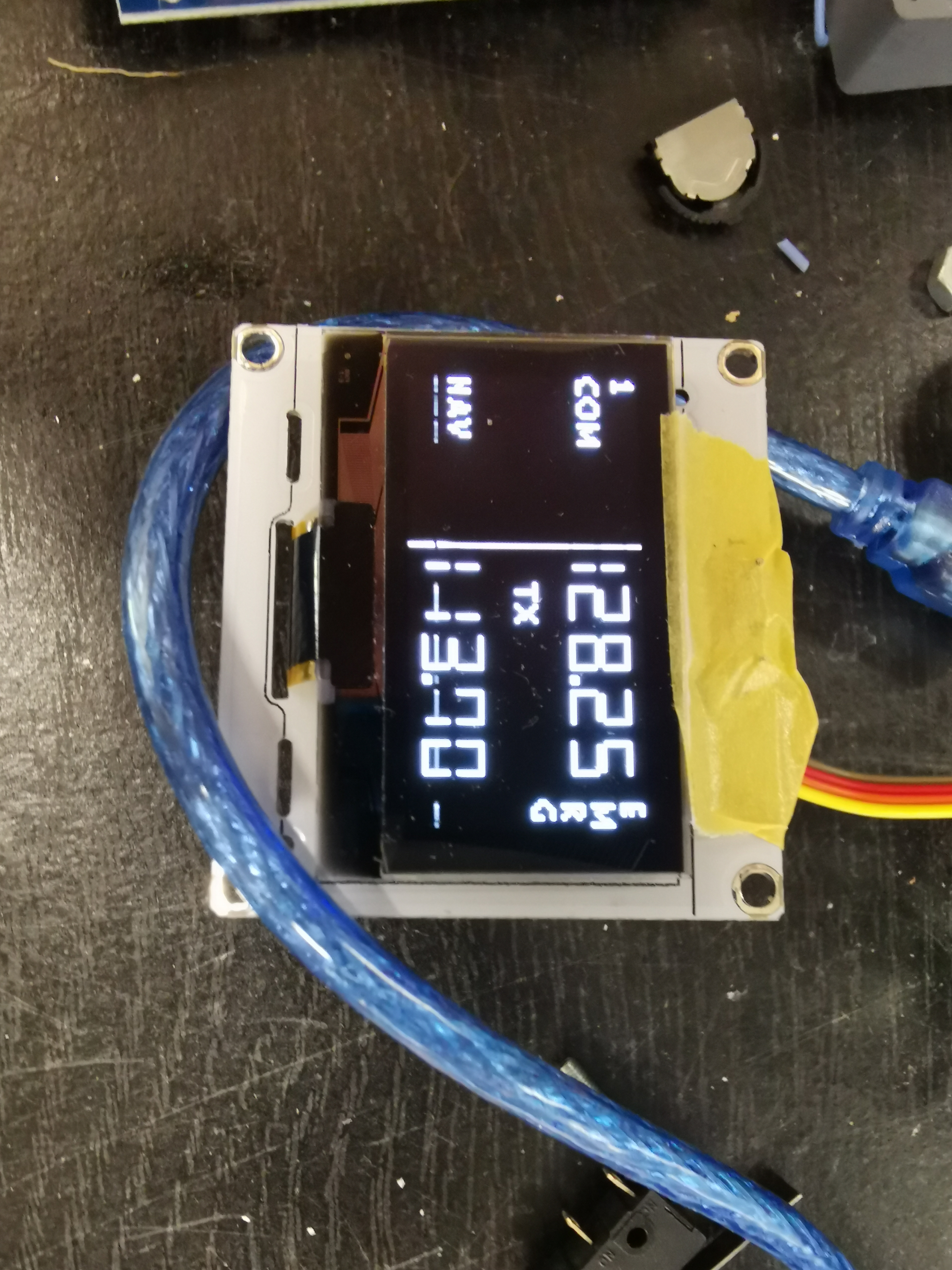
What i don't like on the OLED screens are the fonts, i see your font also looks a bit grainy. (if that's the correct english)
I have found an arduino adafuit font : DSEG7_Classic_Regular_16 which, at least shows the frequencies font smoother.
Forum NavigationCDR Developement and Setup
![]() #1 · December 18, 2017, 3:15 pm
#1 · December 18, 2017, 3:15 pm![]() #2 · April 16, 2021, 7:24 amRoel has reacted to this post.Roel
#2 · April 16, 2021, 7:24 amRoel has reacted to this post.Roel![]() #3 · May 1, 2021, 6:45 pm
#3 · May 1, 2021, 6:45 pm![]() #4 · May 11, 2021, 6:16 am
#4 · May 11, 2021, 6:16 am![]() #5 · June 1, 2021, 8:20 am
#5 · June 1, 2021, 8:20 am![]() #6 · June 1, 2021, 10:27 am
#6 · June 1, 2021, 10:27 am![]() #7 · June 5, 2021, 10:50 pm
#7 · June 5, 2021, 10:50 pm![]() #8 · June 6, 2021, 5:09 pm
#8 · June 6, 2021, 5:09 pm![]() #9 · June 6, 2021, 8:18 pmJason Hite
FlightDeckSoft
#9 · June 6, 2021, 8:18 pmJason Hite
FlightDeckSoft![]() #10 · June 7, 2021, 3:39 am
#10 · June 7, 2021, 3:39 am
2017-10-10