


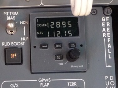
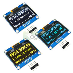
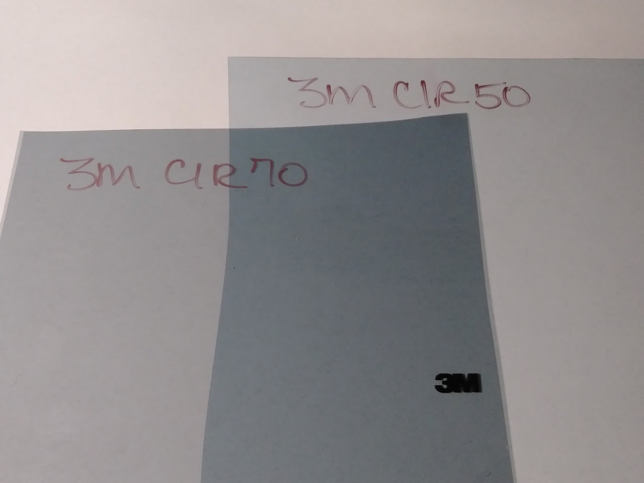
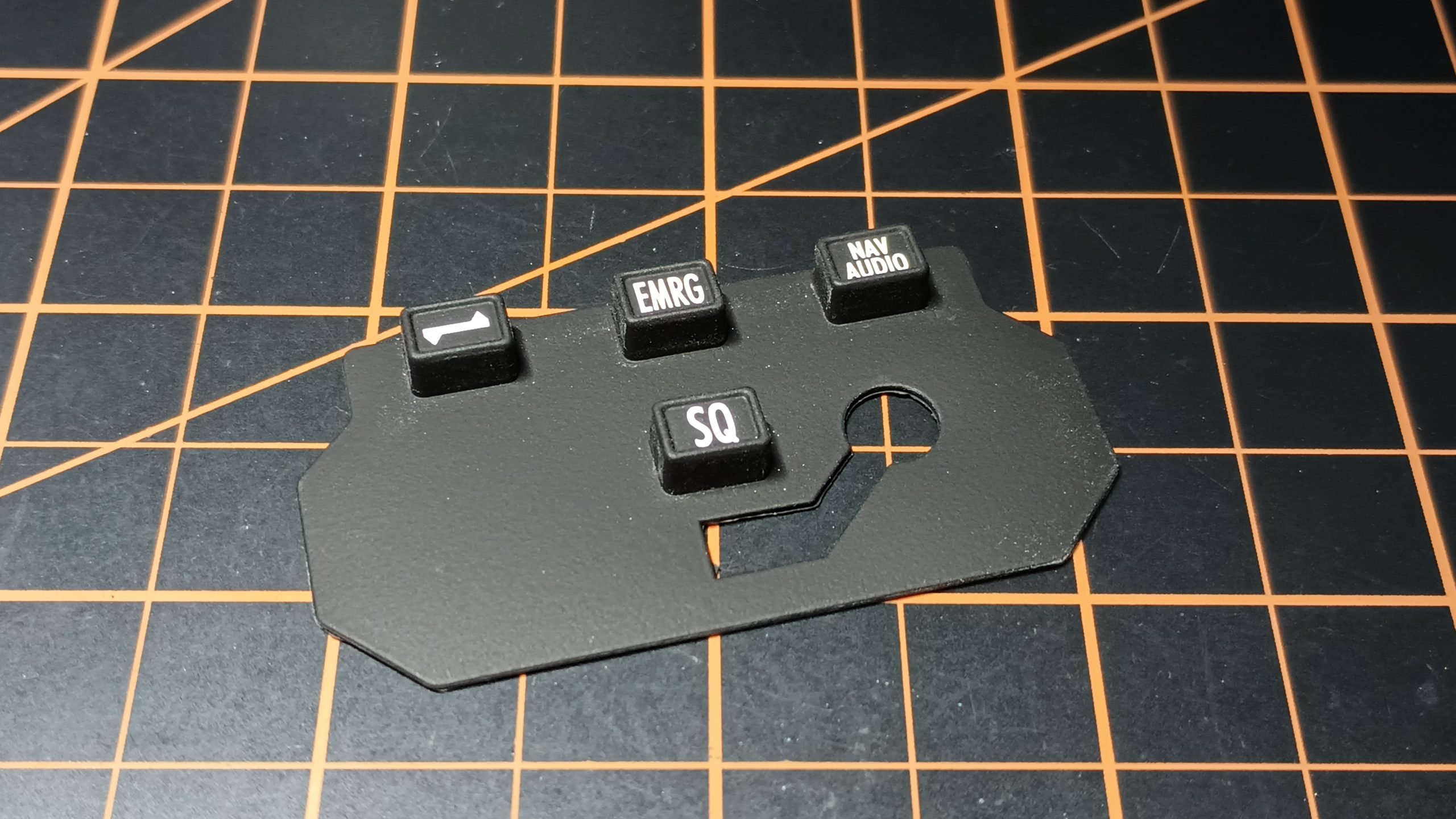
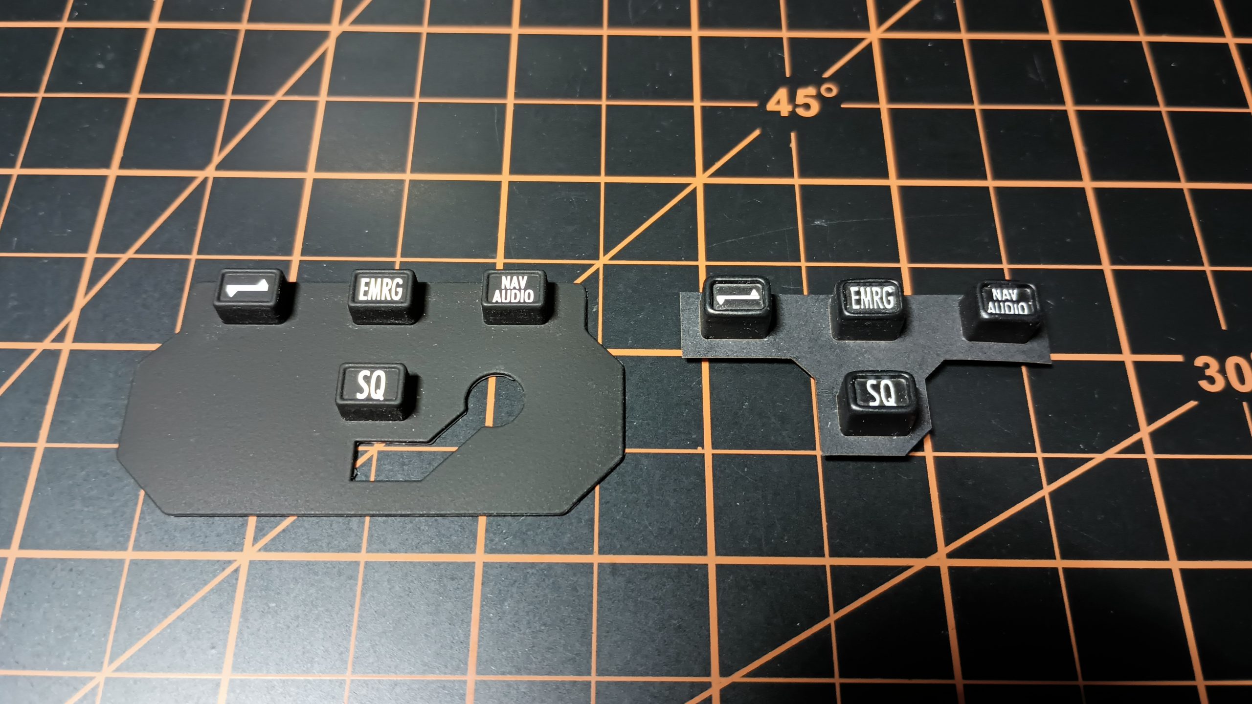
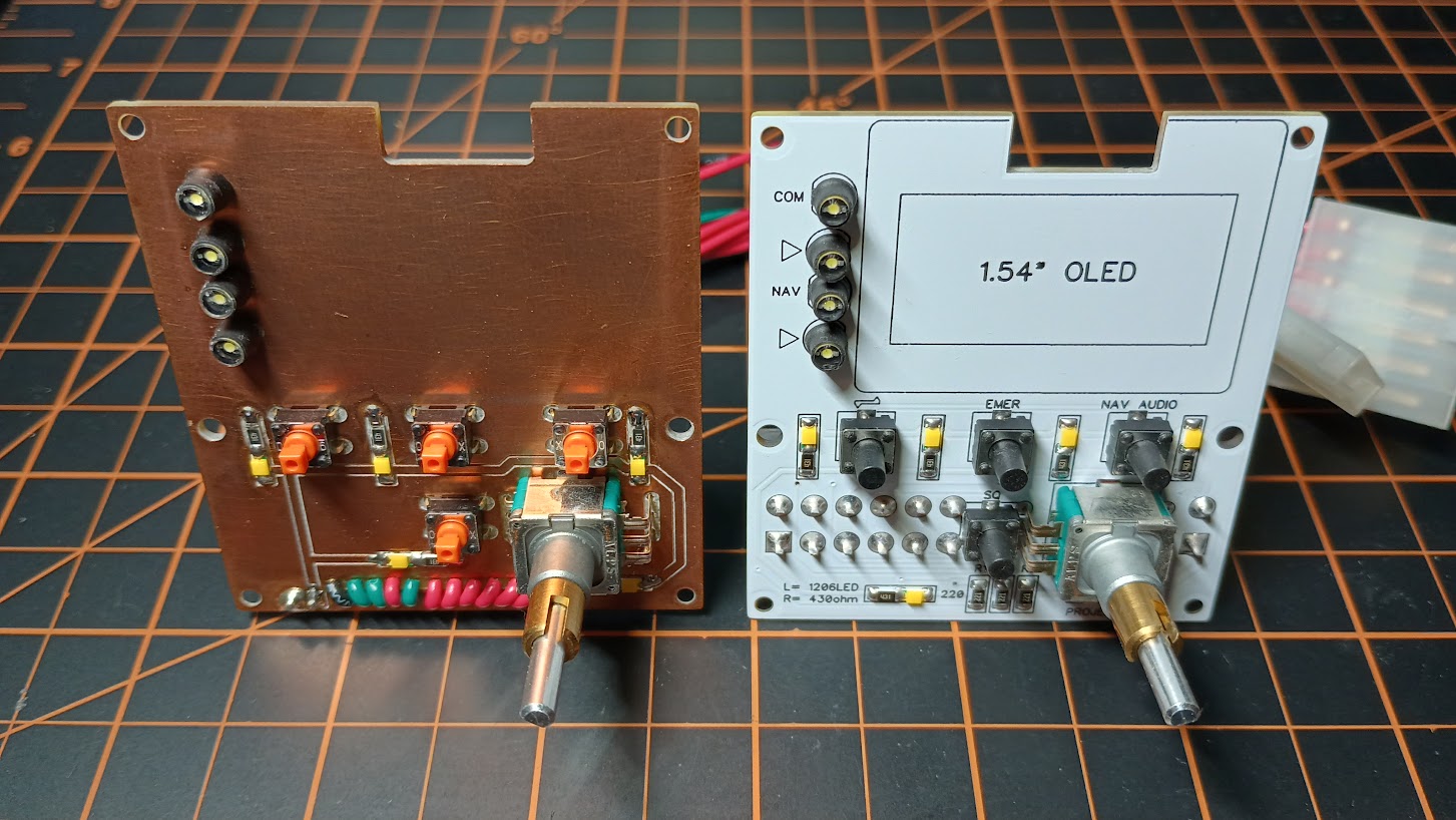
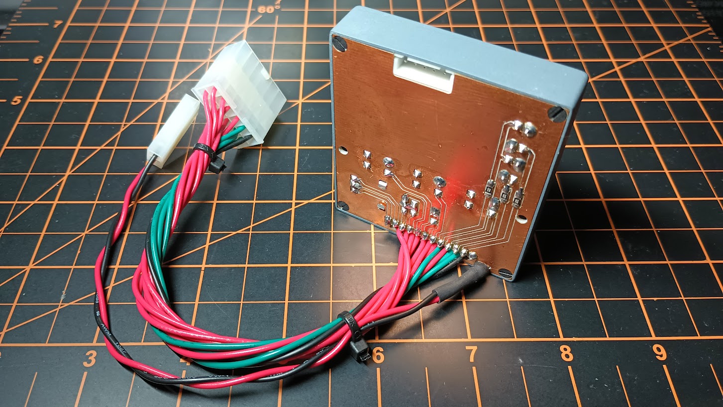
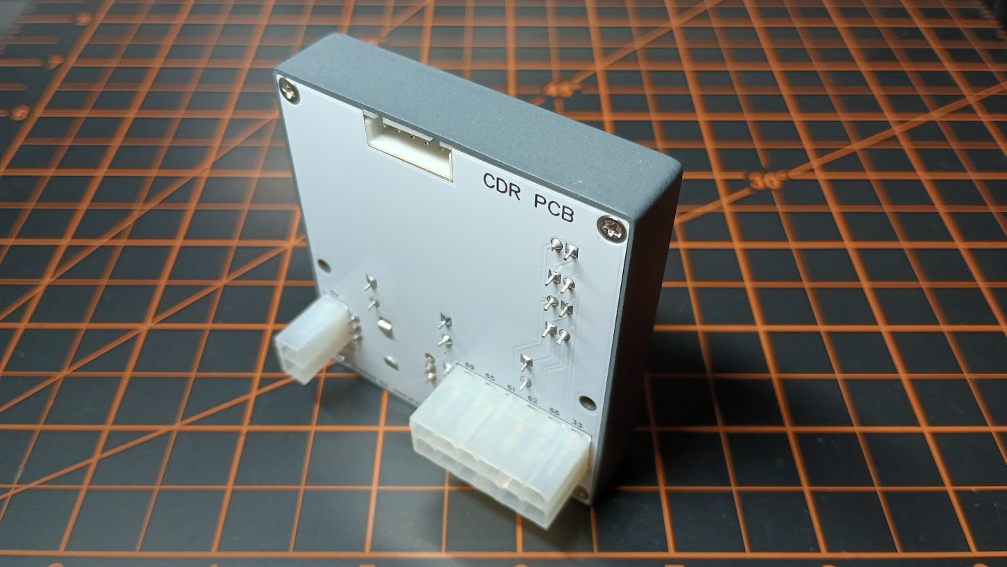
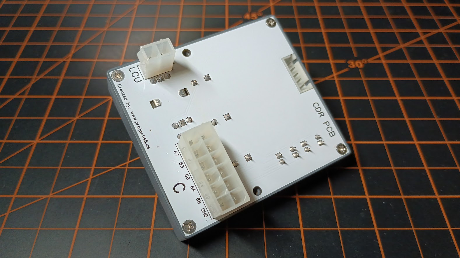
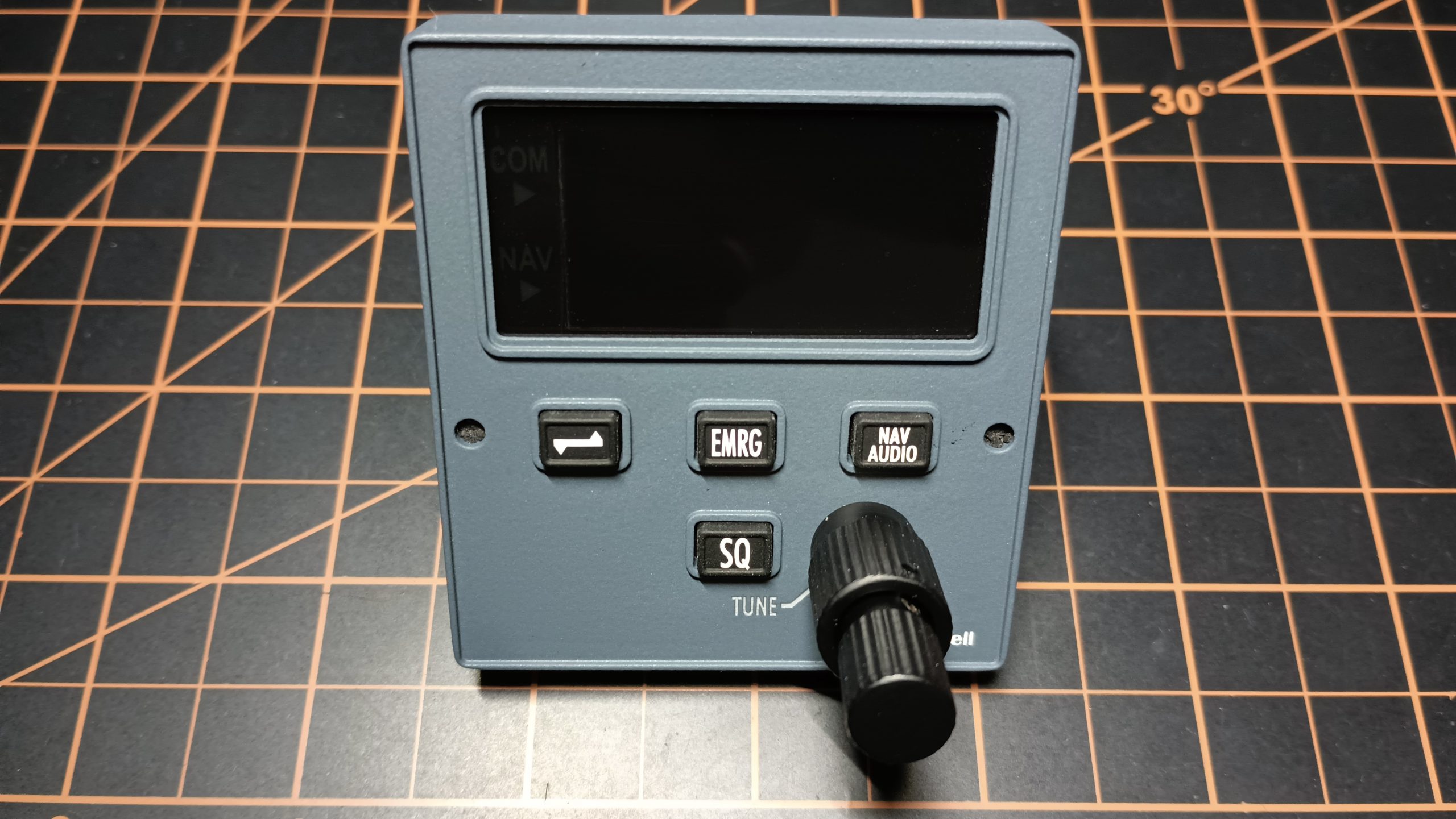
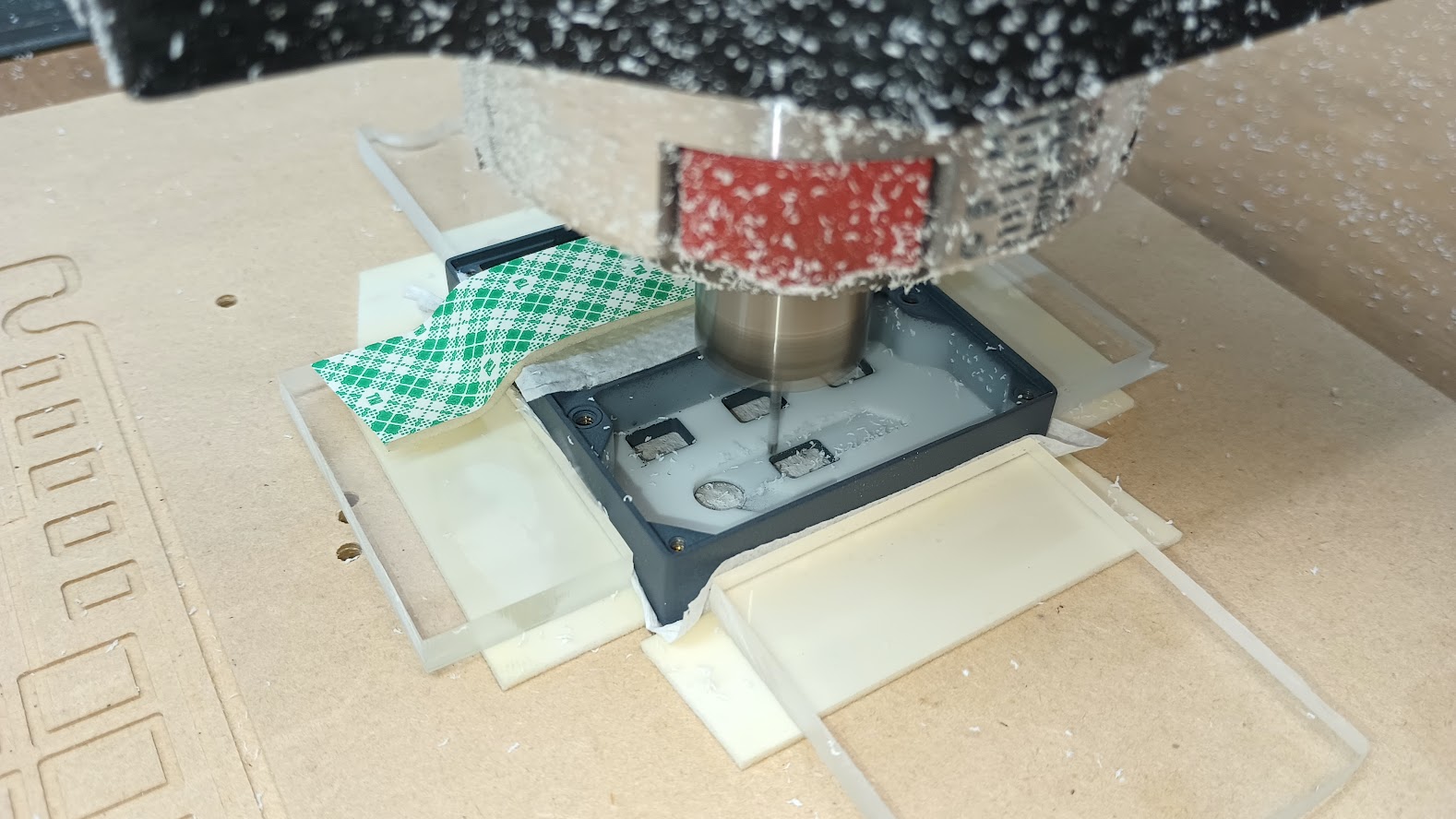
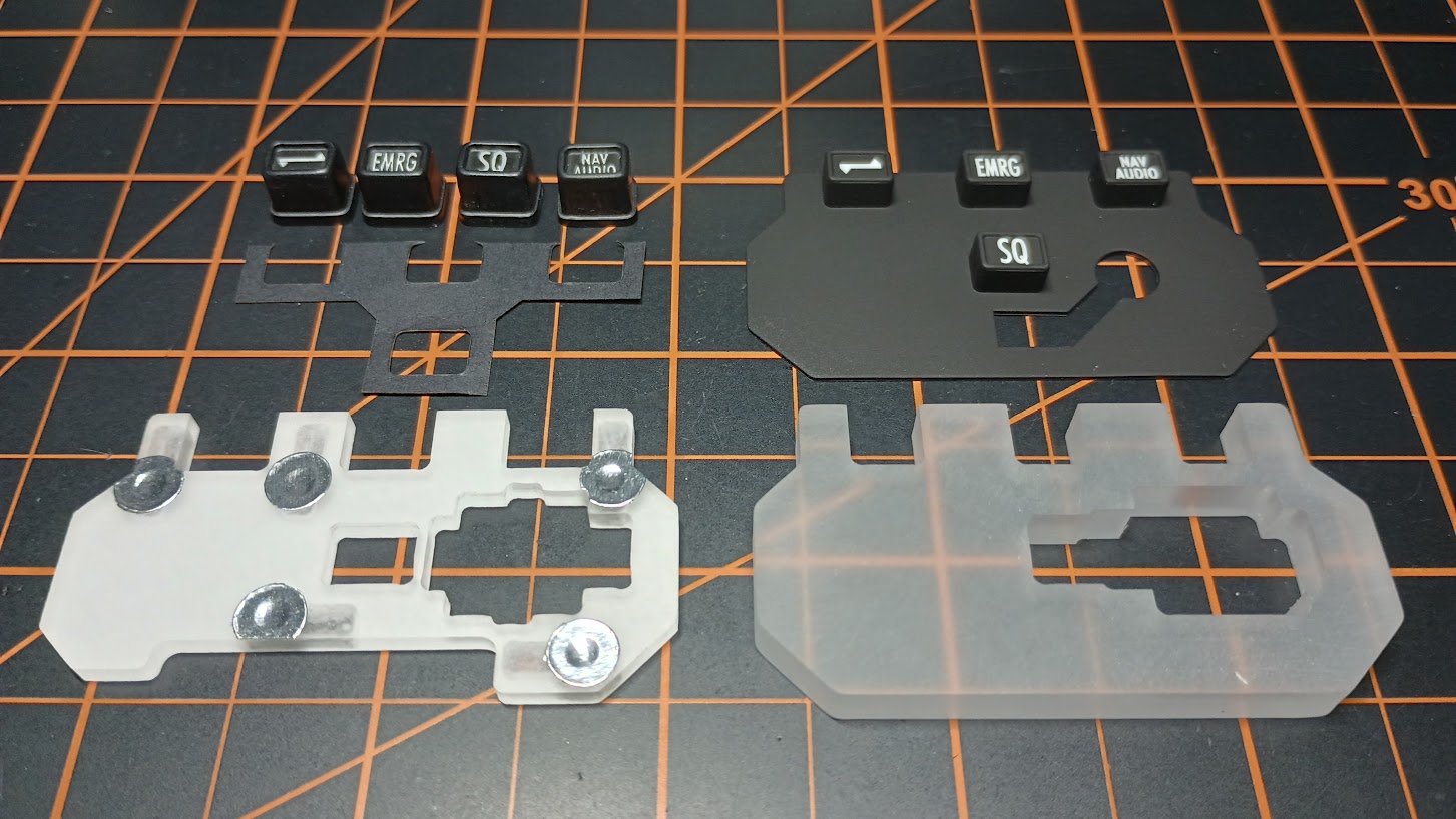
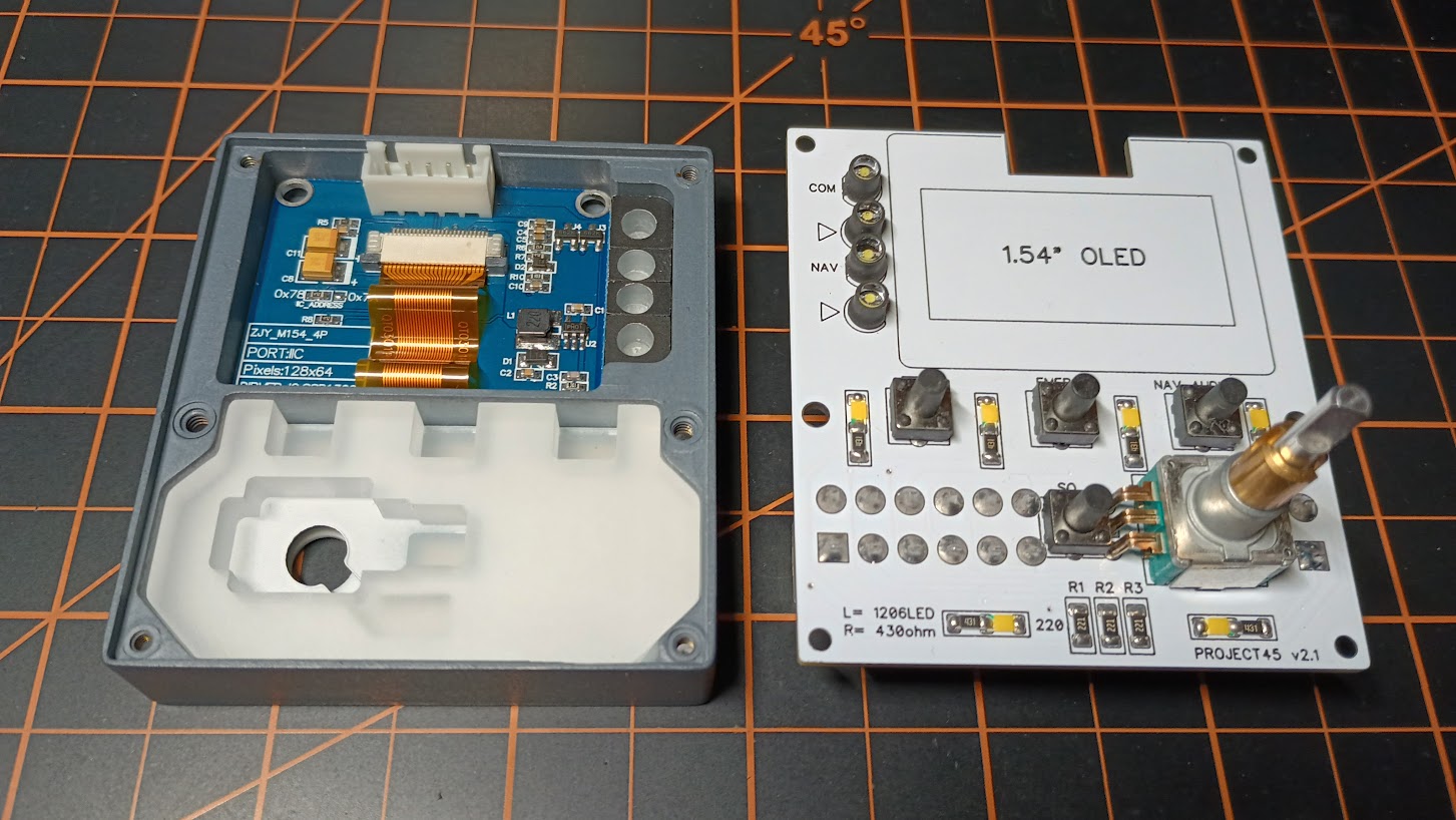
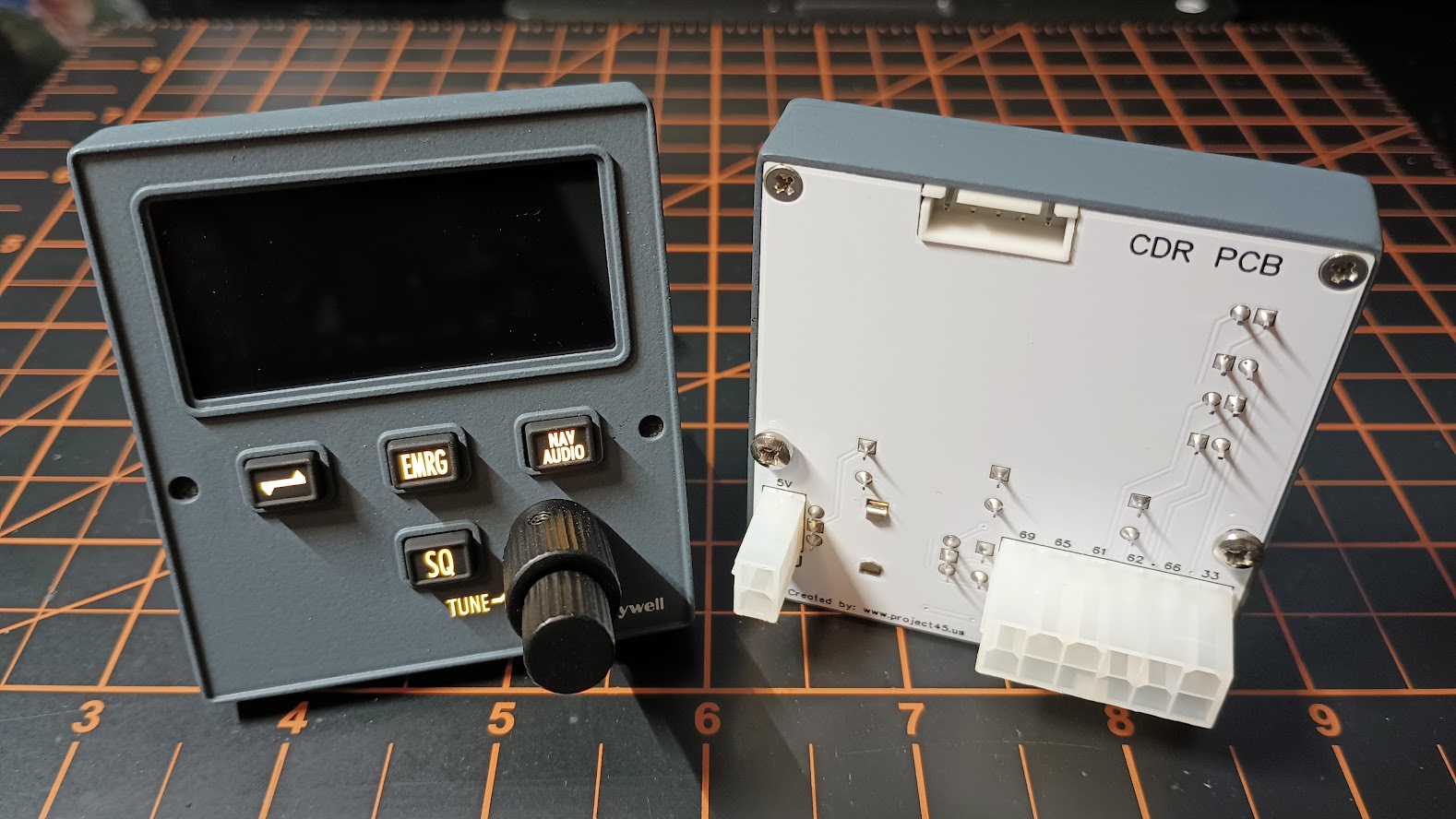
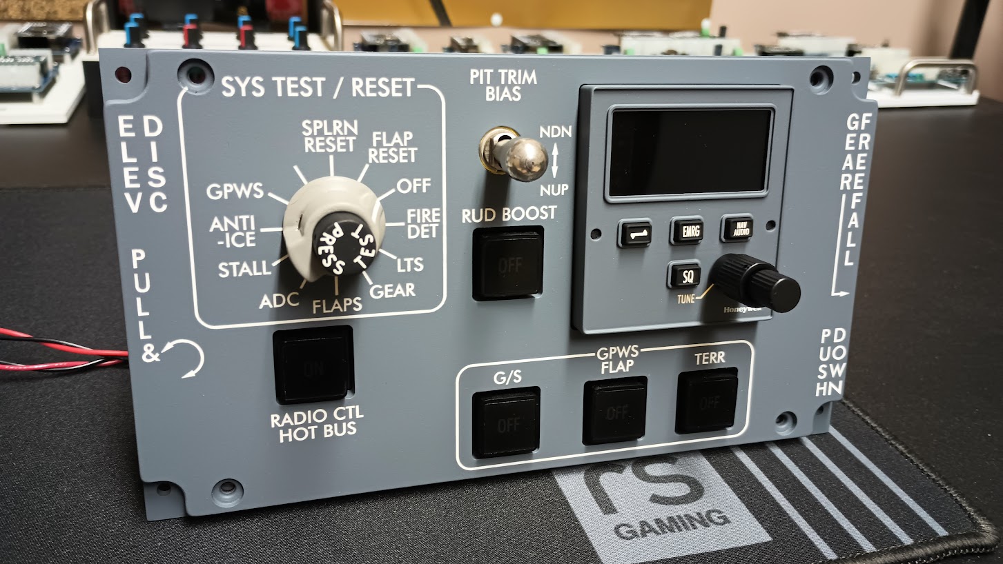
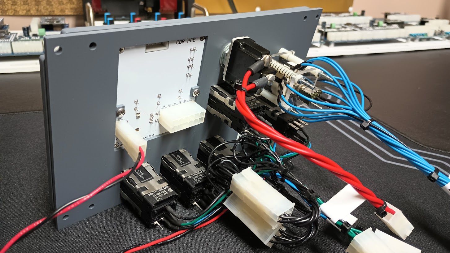
Good find Roel! I've created a bunch of sizes of those fonts using the converter at: http://oleddisplay.squix.ch/#/home. The small text is a bit challenging to get smooth. Good find Roel! I've created a bunch of sizes of those fonts using the converter at: http://oleddisplay.squix.ch/#/home. The small text is a bit challenging to get smooth. Yes that's the one is used also. Yes that's the one is used also. Here is the first demo video of the CDR in action! Still need to tie the buttons in and interface to Jet45 RMU. Pardon the low budget iPhone video. https://www.youtube.com/watch?v=zjOdRF-ty5k Here is the first demo video of the CDR in action! Still need to tie the buttons in and interface to Jet45 RMU. Pardon the low budget iPhone video. That is the most awesomest thing I have seen in a long time Jason! Nice work! I feel like a proud co-parent for some reason. LOL Looks like we have the CDR firmly under control and we are on a nice glide slope. Anything you see that needs adjusting or improved on? The font is perfect! Below is a real deal CDR in a Lear45. You could not ask for better than what you have when comparing to the real deal: One thing that I need your input on so I can finish the rest of these CDRs is the intensity of the LEDs in the light blocks compared to the intensity of the OLED screen. Currently the resistors for the LEDs in the light blocks are 220 Ohm. Judging by the video it looks like we could dim them a little. We could go with 430 Ohm resistors to dim them, or we could use the window tent on just the LED block side of the display. The tent would also help to hide the indicators when they are not lit up. (Not an issue in a dark cockpit) What do you think? Again, incredible work and so cool to see this thing coming to life! That is the most awesomest thing I have seen in a long time Jason! Nice work! I feel like a proud co-parent for some reason. LOL Looks like we have the CDR firmly under control and we are on a nice glide slope. Anything you see that needs adjusting or improved on? The font is perfect! Below is a real deal CDR in a Lear45. You could not ask for better than what you have when comparing to the real deal: One thing that I need your input on so I can finish the rest of these CDRs is the intensity of the LEDs in the light blocks compared to the intensity of the OLED screen. Currently the resistors for the LEDs in the light blocks are 220 Ohm. Judging by the video it looks like we could dim them a little. We could go with 430 Ohm resistors to dim them, or we could use the window tent on just the LED block side of the display. The tent would also help to hide the indicators when they are not lit up. (Not an issue in a dark cockpit) What do you think? Again, incredible work and so cool to see this thing coming to life! Yes Ron, could probably stand to dim them a bit. The other issue is that the color doesn't match the OLED display. The display has a bit of a blue tint to it, and the LEDs are pure white. Yes Ron, could probably stand to dim them a bit. The other issue is that the color doesn't match the OLED display. The display has a bit of a blue tint to it, and the LEDs are pure white. I am going to swing by a window tenting shop to see if I can find some tent with a tad of blue in it. It might be that the little bit of blue tent just covering the LED blocks will do the trick. It will also dim them down a tad and also hide the artwork in ambient light. If they are still too bright, we have the option to use either 300 or 400 Ohm resistors. The blueish tent of the OLED screen reminds me of the early days trying to figure out what color a white light LED is. I would order warm white LEDs and end up with LEDs with a noticeable green tent! Below is a snap shot of our 1.54" OLED color choices. We are using the white one. In this case, I believe this can be easily resolved. Let me see what I can find. I am going to swing by a window tenting shop to see if I can find some tent with a tad of blue in it. It might be that the little bit of blue tent just covering the LED blocks will do the trick. It will also dim them down a tad and also hide the artwork in ambient light. If they are still too bright, we have the option to use either 300 or 400 Ohm resistors. The blueish tent of the OLED screen reminds me of the early days trying to figure out what color a white light LED is. I would order warm white LEDs and end up with LEDs with a noticeable green tent! Below is a snap shot of our 1.54" OLED color choices. We are using the white one. In this case, I believe this can be easily resolved. Let me see what I can find. I found some 3M professional window tent. It's the really good stuff but I was able to get a couple free sample pieces which for what we are using it for will take care of a hundred or more CDRs. The two samples are 3M CIR50 and 3M CIR70 which both have a tad of a bluish tent in them. The solution to a perfect LED/OLED match is going to be one or the other or both. I will make some sample lenses for you to test Jason. Additionally, I am cooking up a half batch of a couple CDRs (two more) along with four more set of buttons to correct the misalignment issue during the first run. I am also going to have some paper light shades cut with the laser so I don't have to cut them by hand. Once I get this batch back from the laser shop I will be sending you a second CDR chase package Jason. I want the CDR to look as good as the the programming you are putting into this thing! I found some 3M professional window tent. It's the really good stuff but I was able to get a couple free sample pieces which for what we are using it for will take care of a hundred or more CDRs. The two samples are 3M CIR50 and 3M CIR70 which both have a tad of a bluish tent in them. The solution to a perfect LED/OLED match is going to be one or the other or both. I will make some sample lenses for you to test Jason. Additionally, I am cooking up a half batch of a couple CDRs (two more) along with four more set of buttons to correct the misalignment issue during the first run. I am also going to have some paper light shades cut with the laser so I don't have to cut them by hand. Once I get this batch back from the laser shop I will be sending you a second CDR chase package Jason. I want the CDR to look as good as the the programming you are putting into this thing! Hey guys, It has been a while since we last covered the CDR. To recap, Jason and I have greatly improved the looks, scale, functionality and performance of this little guy. Additionally, it's way less complicated to figure out how to set it up than what we had available to us in the past. Recently, I just finished up a large batch of CDUs which were only made possible by using Silicone keypads. Thanks to Will Sasse for helping out with the 3D CAD elements. They turned out perfectly! Currently I am working on a large batch of RMUs which will also use Silicone keypads. What does this have to do with the CDRs? The empty space in the Silicone RMU tooling plug was plenty big enough to include the CDR Silicone keypad without adding any additional cost! Once designed and made, Silicone keypads greatly reduce the manufacturing time making panels like the CDUs, RMUs and now the CDRs easier to build and less expensive. Making the buttons using a CNC is possible but it's so time consuming especially if you are making several sets. Here is a comparison photo of the Silicone keypad buttons next to the CNC milled buttons. Without a doubt, I had to take advantage of including the CDR keypads in with the RMUs! But it doesn't stop there. Over the past two and a half years, I have become fairly proficient at designing professionally made pcb! I ended up redesigning the CDR to accept the new Silicone keypad and new pcb to replace the double sided clad. It goes without saying, but I will say it for the fellas that are just picking this up for the first time, pcb is so much easier and cheaper to work with. A piece of blank double sided clad can actually be more expensive than a completed professionally made piece of pcb! (Depending on where you have your PCB manufacturing done.) Although the CDR has greatly improved over our previous solutions, there was still room for improvement. Here is the back side of the CDR using double sided clad. It actually doesn't look bad at all. But using pcb allows us to do a couple things not possible with clad. Silk screen enables us to properly mark plug and pin assignments including individual components. I was also able to eliminate the wiring pigtails. Now the plugs are mounted directly to the backside of the pcb, properly marked and 10 times stronger making these connections more reliable. Can the CDR set up get any easier than this? Three plugs. The LCU is for 5v backlighting. The "C" plug is for all the hardware and LEDs in the CDR. Last but not least, the OLED plug at the top for the display. The next batch of CDR pcb will include some "OLED" silkscreen under that plug. Reference the "C" plug, you can find the pin assignments in the Jet45 AAS Systems Modules document which is found HERE And here is the updated CDR with Silicone keypads and pcb! It works just as before, it might look a little better from the front side, but so much easier to install and setup. And so much easier for me to make available to you guys. Anyone who has the v2.0 CDR and would like a FREE upgrade, just send me back your CDR for the retrofit. Reason being, I have to mill down the inside face by .1" where the new keypad will reside. Or if you have a cnc, I can provide a retro fit kit with G code and you can mill down the inside face yourself.................................if you dare! LOL Or, I can provide a retro fit kit with slightly shorter button hardware where the milling is not required. If you don't yet have one and would like one they are listed at $295 on the HANGAR PRODUCTS page. Hey guys, It has been a while since we last covered the CDR. To recap, Jason and I have greatly improved the looks, scale, functionality and performance of this little guy. Additionally, it's way less complicated to figure out how to set it up than what we had available to us in the past. Recently, I just finished up a large batch of CDUs which were only made possible by using Silicone keypads. Thanks to Will Sasse for helping out with the 3D CAD elements. They turned out perfectly! Currently I am working on a large batch of RMUs which will also use Silicone keypads. What does this have to do with the CDRs? The empty space in the Silicone RMU tooling plug was plenty big enough to include the CDR Silicone keypad without adding any additional cost! Once designed and made, Silicone keypads greatly reduce the manufacturing time making panels like the CDUs, RMUs and now the CDRs easier to build and less expensive. Making the buttons using a CNC is possible but it's so time consuming especially if you are making several sets. Here is a comparison photo of the Silicone keypad buttons next to the CNC milled buttons. Without a doubt, I had to take advantage of including the CDR keypads in with the RMUs! But it doesn't stop there. Over the past two and a half years, I have become fairly proficient at designing professionally made pcb! I ended up redesigning the CDR to accept the new Silicone keypad and new pcb to replace the double sided clad. It goes without saying, but I will say it for the fellas that are just picking this up for the first time, pcb is so much easier and cheaper to work with. A piece of blank double sided clad can actually be more expensive than a completed professionally made piece of pcb! (Depending on where you have your PCB manufacturing done.) Although the CDR has greatly improved over our previous solutions, there was still room for improvement. Here is the back side of the CDR using double sided clad. It actually doesn't look bad at all. But using pcb allows us to do a couple things not possible with clad. Silk screen enables us to properly mark plug and pin assignments including individual components. I was also able to eliminate the wiring pigtails. Now the plugs are mounted directly to the backside of the pcb, properly marked and 10 times stronger making these connections more reliable. Can the CDR set up get any easier than this? Three plugs. The LCU is for 5v backlighting. The "C" plug is for all the hardware and LEDs in the CDR. Last but not least, the OLED plug at the top for the display. The next batch of CDR pcb will include some "OLED" silkscreen under that plug. Reference the "C" plug, you can find the pin assignments in the Jet45 AAS Systems Modules document which is found HERE And here is the updated CDR with Silicone keypads and pcb! It works just as before, it might look a little better from the front side, but so much easier to install and setup. And so much easier for me to make available to you guys. Anyone who has the v2.0 CDR and would like a FREE upgrade, just send me back your CDR for the retrofit. Reason being, I have to mill down the inside face by .1" where the new keypad will reside. Or if you have a cnc, I can provide a retro fit kit with G code and you can mill down the inside face yourself.................................if you dare! LOL Or, I can provide a retro fit kit with slightly shorter button hardware where the milling is not required. If you don't yet have one and would like one they are listed at $295 on the HANGAR PRODUCTS page. Hey guys, Today I finished up the latest modifications to the CDRs I had here in house. Remember, I had to mill out the backside of the lower chamber in the front panel to make room for the new Silicone Keypad and internal light plate. This was a tricky process being that the front panels were already painted and engraved. I used double sided tape, scrap plastic and a paper napkin to hold down and protect the CDR front panel. This worked with 100% success! Here is another interesting photo illustrating the previous method where the buttons were made individually and the light plate had to be painted white on the back side with LED sockets milled into it. The path forward is now a two piece solution, a Silicone keypad and a simplified internal light plate. The idea is to find easier and faster ways to make better quality products with the tools and resources available to us. The assembly process can't get much easier. The buttons have an even stronger tactile feel compared to the previous version. Unless you are paying close attention, you don't even realize the buttons are made of Silicone. I did a test fit of the CDR in the System Test panel just to make sure there were no issues. There is no room for surprises this late in the game! The rear side is clean and easy to understand where the plugs hook into. The CDR is ready to go! Again, if you would like to update your CDR or would like to order one, just send me an email. This CDR works plug and play with the Jet45 AAS software package. Just follow the wiring directions in the Jet45 AAS Systems Modules document HERE. A big thanks to Jason for developing the CDR software and all the other Jet45 AAS software! This project would not be possible without him. Hey guys, Today I finished up the latest modifications to the CDRs I had here in house. Remember, I had to mill out the backside of the lower chamber in the front panel to make room for the new Silicone Keypad and internal light plate. This was a tricky process being that the front panels were already painted and engraved. I used double sided tape, scrap plastic and a paper napkin to hold down and protect the CDR front panel. This worked with 100% success! Here is another interesting photo illustrating the previous method where the buttons were made individually and the light plate had to be painted white on the back side with LED sockets milled into it. The path forward is now a two piece solution, a Silicone keypad and a simplified internal light plate. The idea is to find easier and faster ways to make better quality products with the tools and resources available to us. The assembly process can't get much easier. The buttons have an even stronger tactile feel compared to the previous version. Unless you are paying close attention, you don't even realize the buttons are made of Silicone. I did a test fit of the CDR in the System Test panel just to make sure there were no issues. There is no room for surprises this late in the game! The rear side is clean and easy to understand where the plugs hook into. The CDR is ready to go! Again, if you would like to update your CDR or would like to order one, just send me an email. This CDR works plug and play with the Jet45 AAS software package. Just follow the wiring directions in the Jet45 AAS Systems Modules document HERE. A big thanks to Jason for developing the CDR software and all the other Jet45 AAS software! This project would not be possible without him.CDR Developement and Setup
![]()
![]()
Indeed the small fonts are hard to smoothen, i think it should be possible, but haven't find a good font for those yet.
Indeed the small fonts are hard to smoothen, i think it should be possible, but haven't find a good font for those yet.![]()
![]()
![]()
![]()
![]()
![]()
![]()
![]()
Forum NavigationCDR Developement and Setup
![]() #11 · June 8, 2021, 12:24 amJason Hite
FlightDeckSoft
#11 · June 8, 2021, 12:24 amJason Hite
FlightDeckSoft![]() #12 · June 8, 2021, 1:36 am
#12 · June 8, 2021, 1:36 am![]() #13 · June 8, 2021, 9:50 pmJason Hite
FlightDeckSoft
#13 · June 8, 2021, 9:50 pmJason Hite
FlightDeckSoft![]() #14 · June 9, 2021, 5:12 am
#14 · June 9, 2021, 5:12 am![]() #15 · June 9, 2021, 6:27 am
#15 · June 9, 2021, 6:27 am![]() #16 · June 9, 2021, 11:49 pmJason Hite
FlightDeckSoft
#16 · June 9, 2021, 11:49 pmJason Hite
FlightDeckSoft![]() #17 · June 10, 2021, 6:43 am
#17 · June 10, 2021, 6:43 am![]() #18 · June 12, 2021, 1:46 pm
#18 · June 12, 2021, 1:46 pm![]() #19 · January 9, 2024, 9:36 am
#19 · January 9, 2024, 9:36 am![]() #20 · February 24, 2024, 12:33 am
#20 · February 24, 2024, 12:33 am
2017-10-10