


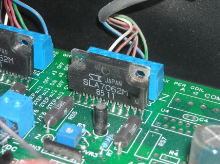
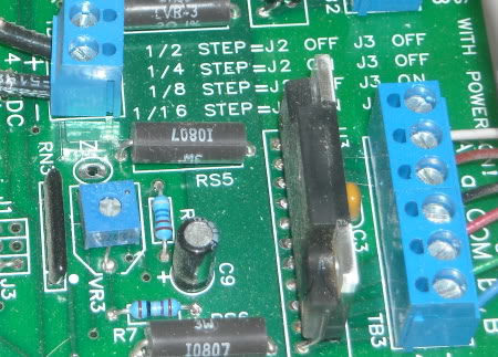
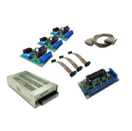
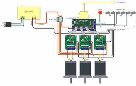
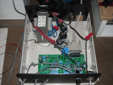
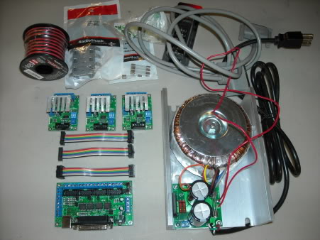
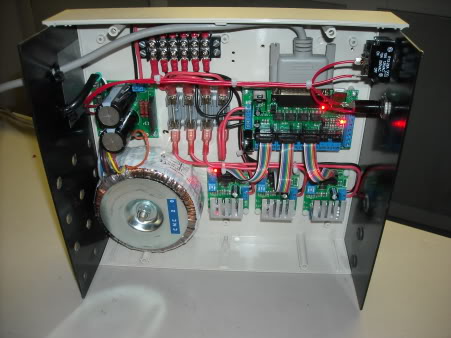
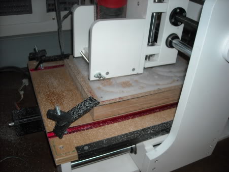
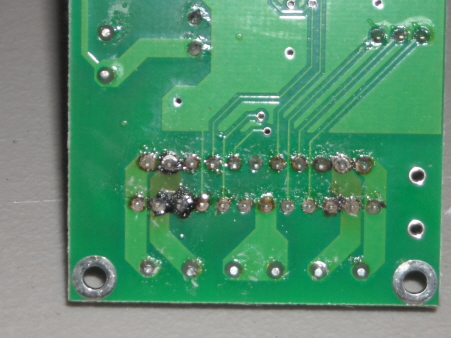
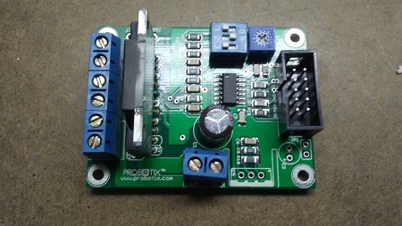
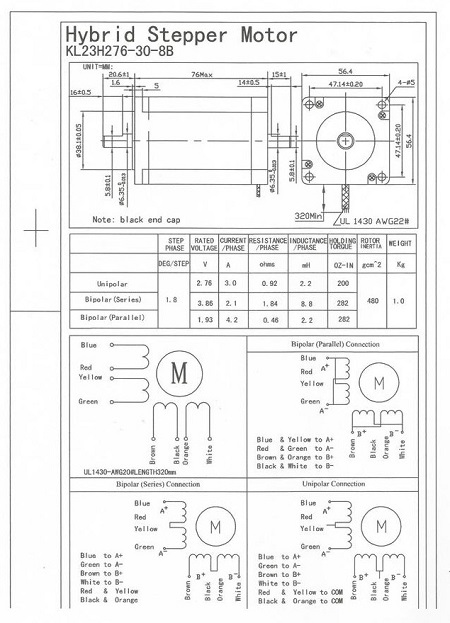
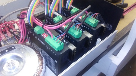
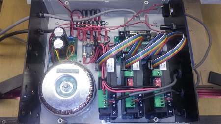
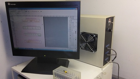
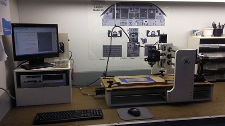
(Original thread started on 10-10-10 by Ron Rollo) Yesterday, I was right in the middle of cutting a part when my CNC control box started smoking and the Z axis froze up..... I opened the control box and saw the smoke coming from the driver chip that is in line with the Z axis output lines. (I did not know a darn thing about the control board for my CNC, but I am learning fast!) After explaining what my issue was to a few of you guys, Mark pointed me to www.hobbycnc.com where I found some useful information, and not just for me! Hobbycnc is a "Do it yourself" kind of CNC website. If you want one of their control boards, you have to buy a kit and solder all the components to the board yourself! I guess that's cool if your really good at soldering. The thing that I found most interesting at this site is that they have a "Spare Parts" page that really has very few parts. They have a kit that will convert your control board to a four axis system, some wire and three different driver chips! The difference in the chips are the amount of pins each one of them has. Here is a link to the spare parts that they have: http://www.hobbycnc.com/products/spare-parts/ The point to all this is that they must expect these driver chips to fail with normal use! These is the same chip that was smoking on my control board. Here is a picture of my busted 21 pin driver chip, SLA7062M. It will cost me $12 plus shipping to repair my CNC: I will tell you this, when the machine is turned off, the Z axis motor is more difficult to turn manually than the other two axis. This is why I suspect the motor might be bad also. I will also check to make sure that there is no binding which would cause it to have difficulty turning. As soon as I get my parts that I order in hand, I will share my results with you. Here is an update on what I am learning about what might have caused this to happen, or at least progressed it in my case: First off, of the three axis, the Z axis is used far less than the other two. Also, it's operational range is far less than the other two. And on top of that, it has a much different work load than the other two axis. What I mean by this is that the X and Y axis work horizontally and their work load from left to right or front to back is equal. The Z axis on the other hand is working like an elevator. It is working against gravity! I took the Z axis worm gear out with the motor to see if there was anything wrong with the stepper motor. What I found was interesting. There was nothing wrong with the motor but the worm gear was very dirty within it's range of motion, more so than the range of motion for the X and Y axis. While I had the gear and motor out was when I discovered just how heavy the vertical gantry was. So when you couple a dirty worm gear with a heavy load, you end up with an overheated driver chip, and in my case a busted driver chip! So to avoid this from happening to your CNC, clean your worm gears, especially the Z access. Second, add a heat sink strip to the driver chips to help pull the heat from them. Mark suggested this to me and I think he even made a post about it here in the hangar. Today I order the SLA7062M 21 pin driver chip for $12 plus $3 shipping. When it arrives, I will most likely take it with the board to a TV repair shop to do the soldering for me. If this is all that is wrong, it will end up being a very easy and inexpensive fix, I hope. (Posted by Mark L. on 10-10-10) In regards to the dirty 'worm' gear or screw as it's more appropriately referred to, I iniitally was using a lithium grease. This however was bad as it collected every chip thrown by the router. Not so bad when it's wood or plastic, but would catch the metal chips as well when machining soft metal. I have since switched to a Teflon spray that I got at the local hardware store. This works way better and the screw and guide tubes don't attract/catch all the chips. About every 5-8 hours of operation I clean and re lubed my screws and guide shafts with the Teflon. Keeps them sliding very nicely and the machine doesn't have to work as hard. Ron has a DXF file I made to make a simple .125" flat heat sink (2.5"x6") for the HobbyCNC controller board. It has holes placed on it so the holes on the driver chips line up and you can attach it via bolts or tap and thread and use screws. Don't forget the heat sink compound! It doesn't need very large screws, we don't want anything shorting. I believe Scott, Eric and Shane also received the file via a reply to a email I made. If anyone else needs a copy let me know and I'll send it to you. Ron, that chip is pretty easy to R&R if you have a good soldering iron and a 'Solder Sucker' (blue plastic spring loaded device, pretty cheap at Radio Shack or Mouser). Heat up the solder joints with the sucker cocked, when the solder melts, at the same time move in with the sucker upper, hit the button! Might take a couple to get it all out. Just be careful not to have to hot a iron and damage the circuit pad trace. Once the solder is out, remove the bad part, replace with new one, solder back in and trim the leads and you are done. Again, soldering back up, hot enough to bind the solder to the trace and the part without damaging the traces, the other end of the spectrum is not hot enough and you end up with a 'cold' solder joint. Looks OK, but doesn't make a good solid connection. One more thing looking at the pic of your controller. Your circuit board seems to be located closer to the rear panel of the box than mine was, you may need to relocate the mounting of the board for clearance to accommodate the heat sink. Not a big deal, just drill four new holes to mount the board elsewhere. Again, a maybe. Also when you replace the chips, unplug everything! Power, cables to servos etc. (Posted by Ron Rollo on 10-10-10) Thanks Mark. I was thinking the same thing when I was looking at it. It is too close and I think the wires where the fuse is would get in the way. As far as the soldering and unsoldering skills that I am working on, I will certainly have them by the time I am finished with this project as a whole. I just don't want to get my practice on really important things like Vince's RMU's or the CNC controller board. I know I can find a source here locally that can knock this little job out for me. On the other hand, the little bit of soldering that I have been doing is turning out pretty good. I spent a few bucks on a solder station to help hold the parts that I am working on. I also did not know how helpful a wet sponge could be to help clean the tip of the iron. I don't need the magnifying glass but I put it back on to show others that this little set up comes with one. The next thing I need to get is the vacuum kit that you are talking about Mark. (Posted by Rand Mathews on 10-10-10) Just to add a little to the conversation, I've used a solder sucker many times and they work well in the right application. Sometimes it's hard to get the tip of the solder sucker close enough to get all the solder out, especially when the pins are real close together. So the alternative method would be to use what is called a solder wick. Basically it's just a braided copper wire that has been treated with flux, so as you heat up your solder connection you place this next to it and as it heats up it will draw the solder into the strands. Anyway thanks for the link to the CNC control board parts, it may come in handy in the future. Also I've always wondered what to lube the feed screws with, so I guess I'll try the Teflon spray (Zep45) and see how that works. (Posted by Ron Rollo on 10-20-10) I took a few pictures of the control board prior to taking it out so that I had a reference of where all the wires go. While looking at the pictures, I noticed that the broken driver chip has a couple cracks in it near the bottom! A few days ago, I got my driver chip in the mail. Yesterday, I dropped it and the board off at a TV repair shop and had it replaced for $20. (I was not in the mood to teach myself the finer points of desoldering and soldering this week.) I made three heat sinks rather than one long one. This way, if ever I blow another chip, it will be a little easier to remove. I used one inch aluminum angle and notched the top part with a miter box saw. Don't forget to use the thermal gunk that goes between the chip and the heat sink. This insures that there is 100% contact between the two parts and will conduct the heat away from the chip properly. UPDATE: I got my CNC all put back together and fired it up................................. The "Z" axis is still not working! The good news is the driver chip did not catch fire and the "X" and the "Y" axis are working fine. I then swapped some wires around to rule out the "Z" axis stepper motor, and it is working fine. So the issue is still in the board. I say it is still in the board because when I took it back out and put a volt meter to it to compare the bad channel ("Z" axis") to the two good channels, ("X" and "Y"), there was a difference in the way one of the capacitors was reading. It was half the value and then after further testing, it was zero value compared to the two good channels. So this rules out a software configuration issue, which I would not know why it would become one. I took the board back to the TV repair shop and the dude is checking to see if all the other capacitors and resistors are good in the "Z" area of the board. Funny thing is, it is looking like there is a problem with the new driver chip that we just replaced, but further testing is necessary! I did check to make sure there were no cross solders or cold solders with my meter with the new chip which there were none. One other thought that I need to check when I get back over to the workshop is to check the wires that go from the board to the stepper motors. I only suspect that there could be a problem here with the wires which would have been caused by the initial chip blowing, which in turn could have caused the new chip to blow due to a short in the wire. I am looking forward to ruling BAD wires out of the equation. Will this fix work or not? The TV repair guy says that he found the problem. One of the traces in the board were broken so he bypassed it using this orange wire! I tested it myself with the volt meter as best as I could and it does appear to be fixed. The thing that bugs me is he has one end of the wire attached to the fourth pin down on the driver chip and then the other end to the sixth pin down on the other row, which appears to have no traces running to it. So I am wondering if there is a problem in the chip itself? And if there was a problem in the new chip, why? Was it damaged in the first place? I don't think so. The only two possibilities that I can come up with is that he damaged it while putting it onto the board or it became damaged when I tried to start it up again. Any thoughts on this mess? (Posted by Mark L. on 10-27-10) He's actually wired pin 11 to pin 8 which is putting a low input on the 'Reset' input. A high causes the logic to be reset, but the issue is that Ron can see no previous trace that was broken or damaged. Nor do the other chips have a trace/circuit path from pin 8 to pin 11. So my hunch is the TV guy is making a bad assumption. (Posted by Ron Rollo on 10-27-10) I should have took a closer look or maybe the TV repair guy should have pointed it out to me, but there is a trace to be seen if you look really close. He must of damaged it during the process of removing and adding the new driver chip. Look close here at the empty forth axis and you can clearly see the trace which is damaged on the "Z" axis. I think I was suffering from tunnel vision and only looking at the "Z" axis area for the broken trace never thinking to look over at this blank axis. You can not see this trace because the driver chip blocks the view, not to mention that the trace is so small that if your light is hitting it wrong, you would never see it. So, I am now very excited to get this board back into my control box and get it fired up. At least this problem is now fixed. I hope there are no other surprises! It worked! I had my fingers crossed when I flipped the switched and it worked! There were lots of lessons learned for me and for you guys following this thread: 1. If you blow your driver chip, you will know you did because that axis will stop working and your CNC board will start smoking! Turn it off. 2. In my case at the least, it is a very cheap fix by replacing just the driver chip for about $12. There were no other components that were damaged on my board other than the driver chip. If your gonna replace the driver chip yourself, be careful not to hurt the traces on the board. (In my case, the TV repair man damaged one of mine.) Some of these PCB traces are very small and if your not paying full attention, you can actually look over it. Last but not least, I think I used the wrong kind of [b]"THICK"[/b] grease to lube my threaded rods which I believe cause the driver chip to fail in the first place. I cleaned all the grease off of all three axis gears and applied a silicone lubricant. Much better! (Posted by Eric Tomlin on 10-28-10) Good to hear Ron. On the cleaning note, I have learned tons just today about my V90 machine, and the manufacturer suggests that even after 5 hours a day on their V90, for weeks on end, they rarely clean it save the occasional vacuum. I think that for now I will stay this course. BTW, I am hoping I just solved my issues too. I will know in a few hours. (Posted by Ron Rollo on 10-29-10) Okay, guess what happened today? I really didn't have anything to cut with my CNC but I did have some scrap .25" thick plastic so I thought I would cut out some Dzus fastener parts while doing other things around the shop just to make sure I really was past my recent problem. Five minutes into the cuts, the Z axis stop lifting and and kept plunging until my bit busted off and the bit collar was pressed up against the plastic. Long story short, the new Z axis driver chip took another $#!% in my control box!!!!!!!!! So I am done with my current set up and I am now in the market for a new control board and power supply. At least I had it up and running long enough to make a few parts to keep me moving forward on my TQ module and I did learn a few lessons, however, if I blow another driver chip on my future board, I am not sure what I would do after what I have just been through. If nothing else, I learned a few things. AHHHHHH!!!!!! My Z driver chip did not blow 100% like the last one did. So I was able to swap stepper motor lines and verify that the problem is again in the board. But I know what your saying, did the motor somehow kill the Z axis driver chip and then straighten up to act like he didn't do nothing? I don't know but the Z axis motor behaved perfectly when I swapped them for that short period of time, and the X axis was the one acting up. So I am in the market for a new CNC board. Currently, I am looking at what Probotix has to offer and they are the front runner as of now. Let me show you one of the reasons why I like Probotix solution and set up: They use a breakout board and the driver chips each have their own board with related components. If ever I have another driver chip failure, it will be as easy as ordering another $38 Driver chip board, unplugging the old one and putting the new one in it's place. The broken one gets thrown in the trash. Hopefully it will be as easy as that. At least I won't have to mess around with unsoldering and soldering and taking a chance with damaged traces. Here is a wiring diagram of their products. It looks very simple! (Posted by Ron Rollo on 01-27-11) All my checks say that the power supply and the motors are good. I asked the question over on the Hobby CNC forum if a motor could cause a chip failure and then operate as if it didn't do anything wrong when you test it with one of the other axis driver chips. Dave kinda brushed that idea off to the side and suggested that it was still an issue with the chip or the wire, or the pins that the wires attach to. I went ahead and got myself a 3 axis hardware kit from Probotix. I upgraded to the PBX-RF breakout board and the more powerful 40VDC 10Amp Linear Power Supply. Sounded like a good idea. You can go to http://probotix.com/ and browse around yourself. I found the site easy and the prices are reasonable. The customer service is great too! So here we go! Buying a CNC machine is a big deal for all of us and can be challenging in the beginning. My current challenge is replacing my knock off Hobby CNC driver board and power supply and replacing it with the new stuff from Probotix. I am keeping the stepper motors, CNC machine frame and case for the guts to go in. Here is a photo of my current set up half pulled apart: And here is a photo of the new stuff taking it's place: I am currently using Keling KL23H276-30-8B Hybrid Stepper Motors: http://kelinginc.net/KL23H276-30-8B.pdf (This file is also saved at the bottom of this post) One of the issues is I want to keep them rather than replace them with what Probotix suggest to use, HT23-280-8 High Torque Stepper Motors. The good thing is that they are very close to being the same thing according to the data sheets. They are both 1.8 deg 200 step per revolution motors. Everything is an exact match with the exception of the color of the wires! So my WARNING to you guys, if you end up swapping parts and mix matching like I am having to do, make sure that you look up the data sheets on the motors and compare it to the wiring diagram (hopefully) provided to you by your new hardware supplier. Again, Probotix has great schematics and drawings to help explain what goes where. I am planning to keep my eighth microstep setting. I have not used anything else, but I hear from Eric and Mark that higher settings sound and feel rough. I have 10 TPI (Turns Per Inch) lead screws for all three axis. If you take this information along with knowing that the motors are 1.8 deg steppers, you end up with 2,000 steps per inch! (360deg / 1.8deg = 200steps x 10TPI = 2,000steps per inch) Okay, here are my questions although I am pretty sure I know the answers: The VREF settings. Probotix has a VREF trimmer and test points built into the boards to easily trim the volts to control the amps being provided to the stepper motors. What is a good amp setting to run the motors at? I am thinking 1.5amp. Power to both sides of the PBX-RF breakout board. The PBX-RF breakout board has what is called isolation chips built into it to protect the computer from power surges from the stepper motors. Because of this, the breakout board needs to receive power from a power supply on both sides of the isolation plane. Probotix gives you one option on the CNC driver side (power supply + and -) and two options on the parallel port side, (power supply + and - or USB port). Eric or Jason, do you know which you are using? My only other question is the pin assignments. I have learned that I at least need to swap the step pin and the direction pin for each of the three axis. I am still looking into if there are any other pins that need to be reassigned in Mach3. No question for you guys, just for me. My goal is to have this thing up and running by Sunday evening. My concern is that the Z axis motor might be the reason the chip blew twice now. That's right, this is the "Blown Driver chip" thread!!!!! I pretty much have my head wrapped around the problem and ready to do this. My only question that still remains is the VREF setting. What is a good amp to run our hobby CNC stepper motors? .5 amps may not be enough power and cause delays and skips in our work. 4 amps would probably be too much and cause over heating issues and there's that term again, "Blown Driver Chips!" I also did my homework related to the step resolution settings. Most of our machines have the ability to choose from full step, half step, quarter step, eighth step and sixteenth step by way of dip switches. Everyone I have talked to agrees that eighth step resolution is best for our application. Again, Probotix has great documentation for us on how to change the hardware settings on the dip switches. However, we have to do a little math to know what the settings are in Mach3, the CNC driver software. (Most of us if not all are using Mach3, there are other programs by the way.) In Mach3 under "Config" and then "Motor Tuning", you will find a box labeled "Steps per" in the bottom left hand corner. This is where we will plug in our step resolution value. To determine your value, you need to know each lead screws TPI, which all of mine are 10 turns per inch. You will also need to know how many steps per revolution your motors are, again, in my case 200. Then do the math. (360deg / 1.8deg = 200steps x 10TPI = 2,000steps per inch) In my case, I come up with 2,000 steps per inch. But I want 1/8" microstep resolution. 2000 / .125 = 16000 NOTE: 16000 is the figure Mach3 wants to see for eighth step resolution for each of the three axis.[/color] So now to put all this to good use. Again, I know this may be elementary to some of you, but I wanted to document this stuff for the newer guys getting or thinking about getting a CNC machine. It might save them a few hours of headaches! (Original thread started on 10-10-10 by Ron Rollo) Yesterday, I was right in the middle of cutting a part when my CNC control box started smoking and the Z axis froze up..... I opened the control box and saw the smoke coming from the driver chip that is in line with the Z axis output lines. (I did not know a darn thing about the control board for my CNC, but I am learning fast!) After explaining what my issue was to a few of you guys, Mark pointed me to http://www.hobbycnc.com where I found some useful information, and not just for me! Hobbycnc is a "Do it yourself" kind of CNC website. If you want one of their control boards, you have to buy a kit and solder all the components to the board yourself! I guess that's cool if your really good at soldering. The thing that I found most interesting at this site is that they have a "Spare Parts" page that really has very few parts. They have a kit that will convert your control board to a four axis system, some wire and three different driver chips! The difference in the chips are the amount of pins each one of them has. Here is a link to the spare parts that they have: http://www.hobbycnc.com/products/spare-parts/ The point to all this is that they must expect these driver chips to fail with normal use! These is the same chip that was smoking on my control board. Here is a picture of my busted 21 pin driver chip, SLA7062M. It will cost me $12 plus shipping to repair my CNC: I will tell you this, when the machine is turned off, the Z axis motor is more difficult to turn manually than the other two axis. This is why I suspect the motor might be bad also. I will also check to make sure that there is no binding which would cause it to have difficulty turning. As soon as I get my parts that I order in hand, I will share my results with you. Here is an update on what I am learning about what might have caused this to happen, or at least progressed it in my case: First off, of the three axis, the Z axis is used far less than the other two. Also, it's operational range is far less than the other two. And on top of that, it has a much different work load than the other two axis. What I mean by this is that the X and Y axis work horizontally and their work load from left to right or front to back is equal. The Z axis on the other hand is working like an elevator. It is working against gravity! I took the Z axis worm gear out with the motor to see if there was anything wrong with the stepper motor. What I found was interesting. There was nothing wrong with the motor but the worm gear was very dirty within it's range of motion, more so than the range of motion for the X and Y axis. While I had the gear and motor out was when I discovered just how heavy the vertical gantry was. So when you couple a dirty worm gear with a heavy load, you end up with an overheated driver chip, and in my case a busted driver chip! So to avoid this from happening to your CNC, clean your worm gears, especially the Z access. Second, add a heat sink strip to the driver chips to help pull the heat from them. Mark suggested this to me and I think he even made a post about it here in the hangar. Today I order the SLA7062M 21 pin driver chip for $12 plus $3 shipping. When it arrives, I will most likely take it with the board to a TV repair shop to do the soldering for me. If this is all that is wrong, it will end up being a very easy and inexpensive fix, I hope. (Posted by Mark L. on 10-10-10) In regards to the dirty 'worm' gear or screw as it's more appropriately referred to, I iniitally was using a lithium grease. This however was bad as it collected every chip thrown by the router. Not so bad when it's wood or plastic, but would catch the metal chips as well when machining soft metal. I have since switched to a Teflon spray that I got at the local hardware store. This works way better and the screw and guide tubes don't attract/catch all the chips. About every 5-8 hours of operation I clean and re lubed my screws and guide shafts with the Teflon. Keeps them sliding very nicely and the machine doesn't have to work as hard. Ron has a DXF file I made to make a simple .125" flat heat sink (2.5"x6") for the HobbyCNC controller board. It has holes placed on it so the holes on the driver chips line up and you can attach it via bolts or tap and thread and use screws. Don't forget the heat sink compound! It doesn't need very large screws, we don't want anything shorting. I believe Scott, Eric and Shane also received the file via a reply to a email I made. If anyone else needs a copy let me know and I'll send it to you. Ron, that chip is pretty easy to R&R if you have a good soldering iron and a 'Solder Sucker' (blue plastic spring loaded device, pretty cheap at Radio Shack or Mouser). Heat up the solder joints with the sucker cocked, when the solder melts, at the same time move in with the sucker upper, hit the button! Might take a couple to get it all out. Just be careful not to have to hot a iron and damage the circuit pad trace. Once the solder is out, remove the bad part, replace with new one, solder back in and trim the leads and you are done. Again, soldering back up, hot enough to bind the solder to the trace and the part without damaging the traces, the other end of the spectrum is not hot enough and you end up with a 'cold' solder joint. Looks OK, but doesn't make a good solid connection. One more thing looking at the pic of your controller. Your circuit board seems to be located closer to the rear panel of the box than mine was, you may need to relocate the mounting of the board for clearance to accommodate the heat sink. Not a big deal, just drill four new holes to mount the board elsewhere. Again, a maybe. Also when you replace the chips, unplug everything! Power, cables to servos etc. (Posted by Ron Rollo on 10-10-10) Thanks Mark. I was thinking the same thing when I was looking at it. It is too close and I think the wires where the fuse is would get in the way. As far as the soldering and unsoldering skills that I am working on, I will certainly have them by the time I am finished with this project as a whole. I just don't want to get my practice on really important things like Vince's RMU's or the CNC controller board. I know I can find a source here locally that can knock this little job out for me. On the other hand, the little bit of soldering that I have been doing is turning out pretty good. I spent a few bucks on a solder station to help hold the parts that I am working on. I also did not know how helpful a wet sponge could be to help clean the tip of the iron. I don't need the magnifying glass but I put it back on to show others that this little set up comes with one. The next thing I need to get is the vacuum kit that you are talking about Mark. (Posted by Rand Mathews on 10-10-10) Just to add a little to the conversation, I've used a solder sucker many times and they work well in the right application. Sometimes it's hard to get the tip of the solder sucker close enough to get all the solder out, especially when the pins are real close together. So the alternative method would be to use what is called a solder wick. Basically it's just a braided copper wire that has been treated with flux, so as you heat up your solder connection you place this next to it and as it heats up it will draw the solder into the strands. Anyway thanks for the link to the CNC control board parts, it may come in handy in the future. Also I've always wondered what to lube the feed screws with, so I guess I'll try the Teflon spray (Zep45) and see how that works. (Posted by Ron Rollo on 10-20-10) I took a few pictures of the control board prior to taking it out so that I had a reference of where all the wires go. While looking at the pictures, I noticed that the broken driver chip has a couple cracks in it near the bottom! A few days ago, I got my driver chip in the mail. Yesterday, I dropped it and the board off at a TV repair shop and had it replaced for $20. (I was not in the mood to teach myself the finer points of desoldering and soldering this week.) I made three heat sinks rather than one long one. This way, if ever I blow another chip, it will be a little easier to remove. I used one inch aluminum angle and notched the top part with a miter box saw. Don't forget to use the thermal gunk that goes between the chip and the heat sink. This insures that there is 100% contact between the two parts and will conduct the heat away from the chip properly. UPDATE: I got my CNC all put back together and fired it up................................. The "Z" axis is still not working! The good news is the driver chip did not catch fire and the "X" and the "Y" axis are working fine. I then swapped some wires around to rule out the "Z" axis stepper motor, and it is working fine. So the issue is still in the board. I say it is still in the board because when I took it back out and put a volt meter to it to compare the bad channel ("Z" axis") to the two good channels, ("X" and "Y"), there was a difference in the way one of the capacitors was reading. It was half the value and then after further testing, it was zero value compared to the two good channels. So this rules out a software configuration issue, which I would not know why it would become one. I took the board back to the TV repair shop and the dude is checking to see if all the other capacitors and resistors are good in the "Z" area of the board. Funny thing is, it is looking like there is a problem with the new driver chip that we just replaced, but further testing is necessary! I did check to make sure there were no cross solders or cold solders with my meter with the new chip which there were none. One other thought that I need to check when I get back over to the workshop is to check the wires that go from the board to the stepper motors. I only suspect that there could be a problem here with the wires which would have been caused by the initial chip blowing, which in turn could have caused the new chip to blow due to a short in the wire. I am looking forward to ruling BAD wires out of the equation. Will this fix work or not? The TV repair guy says that he found the problem. One of the traces in the board were broken so he bypassed it using this orange wire! I tested it myself with the volt meter as best as I could and it does appear to be fixed. The thing that bugs me is he has one end of the wire attached to the fourth pin down on the driver chip and then the other end to the sixth pin down on the other row, which appears to have no traces running to it. So I am wondering if there is a problem in the chip itself? And if there was a problem in the new chip, why? Was it damaged in the first place? I don't think so. The only two possibilities that I can come up with is that he damaged it while putting it onto the board or it became damaged when I tried to start it up again. Any thoughts on this mess? (Posted by Mark L. on 10-27-10) He's actually wired pin 11 to pin 8 which is putting a low input on the 'Reset' input. A high causes the logic to be reset, but the issue is that Ron can see no previous trace that was broken or damaged. Nor do the other chips have a trace/circuit path from pin 8 to pin 11. So my hunch is the TV guy is making a bad assumption. (Posted by Ron Rollo on 10-27-10) I should have took a closer look or maybe the TV repair guy should have pointed it out to me, but there is a trace to be seen if you look really close. He must of damaged it during the process of removing and adding the new driver chip. Look close here at the empty forth axis and you can clearly see the trace which is damaged on the "Z" axis. I think I was suffering from tunnel vision and only looking at the "Z" axis area for the broken trace never thinking to look over at this blank axis. You can not see this trace because the driver chip blocks the view, not to mention that the trace is so small that if your light is hitting it wrong, you would never see it. So, I am now very excited to get this board back into my control box and get it fired up. At least this problem is now fixed. I hope there are no other surprises! It worked! I had my fingers crossed when I flipped the switched and it worked! There were lots of lessons learned for me and for you guys following this thread: 1. If you blow your driver chip, you will know you did because that axis will stop working and your CNC board will start smoking! Turn it off. 2. In my case at the least, it is a very cheap fix by replacing just the driver chip for about $12. There were no other components that were damaged on my board other than the driver chip. If your gonna replace the driver chip yourself, be careful not to hurt the traces on the board. (In my case, the TV repair man damaged one of mine.) Some of these PCB traces are very small and if your not paying full attention, you can actually look over it. Last but not least, I think I used the wrong kind of [b]"THICK"[/b] grease to lube my threaded rods which I believe cause the driver chip to fail in the first place. I cleaned all the grease off of all three axis gears and applied a silicone lubricant. Much better! (Posted by Eric Tomlin on 10-28-10) Good to hear Ron. On the cleaning note, I have learned tons just today about my V90 machine, and the manufacturer suggests that even after 5 hours a day on their V90, for weeks on end, they rarely clean it save the occasional vacuum. I think that for now I will stay this course. BTW, I am hoping I just solved my issues too. I will know in a few hours. (Posted by Ron Rollo on 10-29-10) Okay, guess what happened today? I really didn't have anything to cut with my CNC but I did have some scrap .25" thick plastic so I thought I would cut out some Dzus fastener parts while doing other things around the shop just to make sure I really was past my recent problem. Five minutes into the cuts, the Z axis stop lifting and and kept plunging until my bit busted off and the bit collar was pressed up against the plastic. Long story short, the new Z axis driver chip took another $#!% in my control box!!!!!!!!! So I am done with my current set up and I am now in the market for a new control board and power supply. At least I had it up and running long enough to make a few parts to keep me moving forward on my TQ module and I did learn a few lessons, however, if I blow another driver chip on my future board, I am not sure what I would do after what I have just been through. If nothing else, I learned a few things. AHHHHHH!!!!!! My Z driver chip did not blow 100% like the last one did. So I was able to swap stepper motor lines and verify that the problem is again in the board. But I know what your saying, did the motor somehow kill the Z axis driver chip and then straighten up to act like he didn't do nothing? I don't know but the Z axis motor behaved perfectly when I swapped them for that short period of time, and the X axis was the one acting up. So I am in the market for a new CNC board. Currently, I am looking at what Probotix has to offer and they are the front runner as of now. Let me show you one of the reasons why I like Probotix solution and set up: They use a breakout board and the driver chips each have their own board with related components. If ever I have another driver chip failure, it will be as easy as ordering another $38 Driver chip board, unplugging the old one and putting the new one in it's place. The broken one gets thrown in the trash. Hopefully it will be as easy as that. At least I won't have to mess around with unsoldering and soldering and taking a chance with damaged traces. Here is a wiring diagram of their products. It looks very simple! (Posted by Ron Rollo on 01-27-11) All my checks say that the power supply and the motors are good. I asked the question over on the Hobby CNC forum if a motor could cause a chip failure and then operate as if it didn't do anything wrong when you test it with one of the other axis driver chips. Dave kinda brushed that idea off to the side and suggested that it was still an issue with the chip or the wire, or the pins that the wires attach to. I went ahead and got myself a 3 axis hardware kit from Probotix. I upgraded to the PBX-RF breakout board and the more powerful 40VDC 10Amp Linear Power Supply. Sounded like a good idea. You can go to http://probotix.com/ and browse around yourself. I found the site easy and the prices are reasonable. The customer service is great too! So here we go! Buying a CNC machine is a big deal for all of us and can be challenging in the beginning. My current challenge is replacing my knock off Hobby CNC driver board and power supply and replacing it with the new stuff from Probotix. I am keeping the stepper motors, CNC machine frame and case for the guts to go in. Here is a photo of my current set up half pulled apart: And here is a photo of the new stuff taking it's place: I am currently using Keling KL23H276-30-8B Hybrid Stepper Motors: http://kelinginc.net/KL23H276-30-8B.pdf (This file is also saved at the bottom of this post) One of the issues is I want to keep them rather than replace them with what Probotix suggest to use, HT23-280-8 High Torque Stepper Motors. The good thing is that they are very close to being the same thing according to the data sheets. They are both 1.8 deg 200 step per revolution motors. Everything is an exact match with the exception of the color of the wires! So my WARNING to you guys, if you end up swapping parts and mix matching like I am having to do, make sure that you look up the data sheets on the motors and compare it to the wiring diagram (hopefully) provided to you by your new hardware supplier. Again, Probotix has great schematics and drawings to help explain what goes where. I am planning to keep my eighth microstep setting. I have not used anything else, but I hear from Eric and Mark that higher settings sound and feel rough. I have 10 TPI (Turns Per Inch) lead screws for all three axis. If you take this information along with knowing that the motors are 1.8 deg steppers, you end up with 2,000 steps per inch! (360deg / 1.8deg = 200steps x 10TPI = 2,000steps per inch) Okay, here are my questions although I am pretty sure I know the answers: The VREF settings. Probotix has a VREF trimmer and test points built into the boards to easily trim the volts to control the amps being provided to the stepper motors. What is a good amp setting to run the motors at? I am thinking 1.5amp. Power to both sides of the PBX-RF breakout board. The PBX-RF breakout board has what is called isolation chips built into it to protect the computer from power surges from the stepper motors. Because of this, the breakout board needs to receive power from a power supply on both sides of the isolation plane. Probotix gives you one option on the CNC driver side (power supply + and -) and two options on the parallel port side, (power supply + and - or USB port). Eric or Jason, do you know which you are using? My only other question is the pin assignments. I have learned that I at least need to swap the step pin and the direction pin for each of the three axis. I am still looking into if there are any other pins that need to be reassigned in Mach3. No question for you guys, just for me. My goal is to have this thing up and running by Sunday evening. My concern is that the Z axis motor might be the reason the chip blew twice now. That's right, this is the "Blown Driver chip" thread!!!!! I pretty much have my head wrapped around the problem and ready to do this. My only question that still remains is the VREF setting. What is a good amp to run our hobby CNC stepper motors? .5 amps may not be enough power and cause delays and skips in our work. 4 amps would probably be too much and cause over heating issues and there's that term again, "Blown Driver Chips!" I also did my homework related to the step resolution settings. Most of our machines have the ability to choose from full step, half step, quarter step, eighth step and sixteenth step by way of dip switches. Everyone I have talked to agrees that eighth step resolution is best for our application. Again, Probotix has great documentation for us on how to change the hardware settings on the dip switches. However, we have to do a little math to know what the settings are in Mach3, the CNC driver software. (Most of us if not all are using Mach3, there are other programs by the way.) In Mach3 under "Config" and then "Motor Tuning", you will find a box labeled "Steps per" in the bottom left hand corner. This is where we will plug in our step resolution value. To determine your value, you need to know each lead screws TPI, which all of mine are 10 turns per inch. You will also need to know how many steps per revolution your motors are, again, in my case 200. Then do the math. (360deg / 1.8deg = 200steps x 10TPI = 2,000steps per inch) In my case, I come up with 2,000 steps per inch. But I want 1/8" microstep resolution. 2000 / .125 = 16000 NOTE: 16000 is the figure Mach3 wants to see for eighth step resolution for each of the three axis.[/color] So now to put all this to good use. Again, I know this may be elementary to some of you, but I wanted to document this stuff for the newer guys getting or thinking about getting a CNC machine. It might save them a few hours of headaches! (Posted by Mark L. on 01-28-11) My information is based on the HobbyCNC Pro driver board and the stepper motors that I have. The motors which are the same as what Ron has are rated at 3 amps. The important part to remember is that they are rated to work and draw up to 3 amps. This is based on load. The driver can be set and capable of supplying 3 amps, but the motors will only draw what’s needed based on load. For example, if you are simply jogging from one location to the other and based on speed and even though the driver maybe configure for 3 amps, the motors may only draw 1.5 amps to perform that move. The more load the more current draw. For me, I don’t want a motor stalling and screwing up my job in process because I had it under powered. Here’s the info on setting the ‘VRef’ for the HobbyCNC board and though it won’t apply to the Probotix, this is the procedure as to how it’s done for this system. Current Adjustment MOST IMPORTANT! The stepper motor current MUST be adjusted before connecting any steppers to the driver board. Each axis can be adjusted to a different value. Current MUST be 500ma up to 3A per coil. With power applied to TB6 (12VDC min, 42VDC max) use a voltmeter with the black lead connected to TB6 terminal “minus” and the red lead touching the axis pad to the left of VR1, VR2, VR3, VR4. Clockwise movement increases the voltage, counter clockwise decreases the voltage. IDLE CURRENT REDUCTION MUST BE DISABLED (J4 jumper ON) WHILE SETTING Vref. The following voltage MUST be set to achieve the correct amperage: 500ma = .070VDC (seven hundredths of a volt) 1A= .14VDC (fourteen hundredths of a volt) 1.5A= .21VDC (twenty-one hundredths of a volt) 2A= .28VDC (twenty-eight hundredths of a volt) 2.5A= .35VDC (thirty-five hundredths of a volt) 3A= .42VDC (forty-two hundredths of a volt) For any amperage not shown use the following formula: desired amps times .14 equals Vref. Again, Idle current reduction MUST be disabled when setting the Vref values. We recommend fan (24VDC) cooling and heat sink at 2A or more. The wiring diagram has a suggested heat sink from 1/8” aluminum flat stock. You can try the 1/8 stepping, but may want to stay with 1/4, you will lose power in the stepping from 1/4 to 1/8 and never increase stepping to increase resolution. The biggest power loss would come in the transition from say a cut to a rapid jog. IE: 15ipm to 50ipm. 1/8 stepping from 1/4 means the kernal in Mach3 has to work twice as fast to keep up with sending the information and if the i/o bus or the computer isn't fast enough, you could experience stalls or skipped steps. (Posted by Ron Rollo on 01-30-11) Thanks Mark, I have been running 16th" step and it has been running fine. I was also able to physically verify that all my lead screws are 10TPI. So far, I have all the old stuff pulled out and the new stuff bolted in place. I had to take the power supply out of it's aluminum case to get it all to fit. (Posted by Mark L. on 01-30-11) Looks good Ron, I'm surprised at how small the heat sinks are though, especially after the monster heat sink I made for mine. Looking forward to hear it's throw'in chips! (Posted by Ron Rollo on 02-01-11) Hey Mark, those are my heat sinks I pulled off of my old Hobby CNC chip drivers that I made and got about 30 minutes worth of cutting with. They should be fine, better than nothing which is what it came with! I got the controller box all wired up and did a few test. I held my breath and powered it up. Nothing blew up this time! No smoke either. I really didn't expect smoke but it seems like my most recent experience with the CNC involves smoke! Take a look at this layout. Looks nice and neat. If it runs as good as it looks, I am back in business! I also reoriented the box so that it stands on end. I also labeled the stepper motor wires coming into the control box. It seems lately I am in the need to know which is which. 1. I conducted a power only test. 2. Set the VREF to 3.0 AMP. 3. The micro steps are set to eighth step. 4. The pins and ports are configured for the new Probotix stuff. Are that is needed now is to hook up the stepper motors and hopefully, run some more successful test! UPDATE: Well today was the day I finally got it all put back together, and it works! I held my breath for a dry run cut and then I put the bit to the plastic. So far I have cut out several smaller items with no issues. I have been keeping an eye on the heat of the heat sinks and motors. All seems good there too: Probably works better than any I have seen lately! One more update next week in reference to the fan and hopefully, my blown driver chip issue is behind me once and for all! The CNC and the new hardware has been working great. My father has been running the heck out of it for the past four days making some smaller parts. Speaking of, if anyone needs a DZUS fastener kit, I have three sets ready to go. However, my CNC computer took a dirt nap this afternoon while my father was running it. It is a problem that has nothing to do with the CNC and the CNC did not cause it. But none the less, it is at the PC repair shop seeing if it is done or can be saved. The computer is now fixed and driving the CNC which is cutting chips. I think I am finally over the issue I was having with my CNC. (I have come a long way since the "blown driver chip" if you remember) Oh yeah, the computer had a bad video card in it. Apparently, it has always been bad because it was screwed up from the day I bought it. I managed to get it to work until last week when it died for real! And here is the news on the blasted fan issue! Mouser canceled my order for the 48v OD9225-48LB fan that would work so perfectly for my CNC case. I am guessing that they can not get it any longer. So I placed an order with: http://www.alliedelec.com/search/searchresults.aspx?N=0&Ntk=Primary&Ntt=OD922548HB I never would have thought that a darn fan would be the thorn in the side of my CNC. Now we know why Probotix does not use 48v fans in their units with the larger power supplies! I got my 48v Orion fan. I have it installed and it is working great! I am finally ready to say the "Blown driver chip" is behind me. It only took 4 months and replacing just about everything. The good news is I feel I have a much better CNC set up and I have learned tons along the way to prepare myself for the next issue that's rolling down the pipe. (Posted by Ron Rollo on 01-29-13) Today the smoke got out of the Z axis driver chip again. (The magic got out as DonnyRay would say.) But this time, I think I am ready. If you recall, the last time my Z axis driver chip went out, my CNC was down for almost five months as I struggled with what I was going to do to fix it. Ultimately, I trashed everything in my control box and started from scratch with all new components from Probotix! http://www.probotix.com/index.php?view=home Anyway, there design is if you have one driver chip blow, you just change out that module and you should be back up and running. Here is a photo of the inside of my control box that I built two years ago. If you look closely in this photo, you can actually see the crack where the magic escaped from. (It runs across the "8MR") More evidence of the issue at hand: So as of this moment, I have the replacement part ordered and I just got an email from them advising that the package has already been shipped. This company sell top notch stuff and their costumer service is second to none! Hopefully I will have the CNC running within a week and not months like last time. I'll keep you posted. (Posted by Mark L. on 01-29-13) Glad that you will get it back up and running easily this time. The fact that you have blown the Z-axis twice warrants looking into why that happened. It will most likely do it again if nothing else changes. There's a lot more load on that Z-axis than the X or Y. I found that Miguel or whatever his name was, used some cheap connectors between the controller and the stepper motors and I was getting a voltage drop across the connectors (shouldn't happen) and after 15 minutes of use, you couldn't touch the connectors. I replaced all of them with high quality gold plated connectors and they have never even gotten warm since. Another area to look at, are you using a Colt router yet? If not, what's the weight of what your using compared to a Colt? Maybe the weight is borderline for it to handle or you could have a flaky stepper motor drawing more than it should. The lead screw nut could be bad causing some additional drag as well. I also added a bearing to the bottom of my Z-axis lead screw as ours did not have one which will cause some side torque and binding when lifting the router up. Just a few ideas as to what I did to my machine to improve the operation and reliability of it. (Posted by Will Sasse on 01-29-13) Same axis twice? I agree with Mark, its highly possible that something else smells in your setup. Might be time to get a water-cooled spindle motor and enjoy real speed! (Posted by Manfred on 01-30-13) What about those gecko drives? They handle huge currents. Given that it is only one axis that keeps failing, you only need to get one. Otherwise, what about a simple counterweight? I have used a pulley attached to a roof beam and used a PVA bottle that weighed as much as the spindle. Worked very well. (Posted by Mark L. on 01-30-13) A counterweight is always a plus. I'm still on my original controller with no issues, but I did have to replace the bridge rectifier in my power supply as it was bad and added a massive heat sink to the drivers, but nothing since. (Posted by Ron Rollo on 02-03-13) I have heard that the most common chip to blow is the Z and I would agree! And it blows for all the reasons stated above. I was using a heavier Craftsman router with a whole lot more plastic surrounding it up until about three months ago. So it is possible that the damage was mostly done with the heavier router during the first 18 months of the life of the newer setup. Now I have a Colt with a tool holder from Probotix. The new setup probably weighs about a half pound less which can only be good. I do like the idea of a counter weight to offset the router. I'm going to do this!!! Maybe I can get three years of life out of this next one. Well, I have had a chance to install the new driver chip module and the Z axis still does not work. I checked the fuses and found that the fuse that runs power to the Z axis driver chip module was blown so I replaced it thinking that would solve the problem. Nope. Then I spent about 45 minutes checking and double checking all the wires and isolated the problem to the breakout board. In other words, the Z axis driver chip module needed to be replaced, the fuse was blown and needed to be replaced and last but not least, apparently, the breakout board also needs to be replaced. I was doing some more reading on the breakout board and found this: "The PBX-RF is an Isolated Parallel Port Breakout Board designed specifically for Hobby CNC machines. It is compatible with a variety of Parallel Port CNC Control Software. The isolation layer protects the PC from potential damage from spikes or short circuits on the high voltage motor drivers used in CNC." So I wonder if in the process of protecting the computer from the Z axis driver chip module frying, the breakout board fried by design. In any case, it's another $60 and four more days of delay. And the breakout board is on the way........ (Posted by Ron Rollo 02-10-13) I forgot to tell you how things worked out! I got the breakout board from Probotix a few days ago in record time as usual, took the old one out and installed the new one. I turned the CNC on and the Z axis still did not work! At this point I was pissed as you could imagine. I took a minute and just looked things over and decided to cycle the three dip switches on the Z axis driver chip module. And what do you know, the Z axis came to life, however, it was running at four times the speed. So I put them back in their original positions and the stepper speed corrected itself. (I have no idea what that was all about but it worked!) Then I swapped out the new breakout board and put the old one back in and the CNC still worked as designed. So long story short is that I did not need the new breakout board. All I needed to do was cycle the dip switches. Lesson learned. I called Probotix and they are going to allow me to send the new breakout board back in exchange for a spare stepper driver board for just about an even exchange. This way, if I blow another one I can get back to cutting within a few minutes instead of a few weeks! (Posted by DonnyRay Jones on 02-11-13) DIP switches are famous for developing intermittent connections. You can often prevent this failure mode by cycling each switch position several times once or twice a year. PRO TIP: Before you start cycling DIP switches - take a quick photo of the switch positions so you'll know for sure how to put them back in the correct positions. (Posted by Mark L. on 01-28-11) My information is based on the HobbyCNC Pro driver board and the stepper motors that I have. The motors which are the same as what Ron has are rated at 3 amps. The important part to remember is that they are rated to work and draw up to 3 amps. This is based on load. The driver can be set and capable of supplying 3 amps, but the motors will only draw what’s needed based on load. For example, if you are simply jogging from one location to the other and based on speed and even though the driver maybe configure for 3 amps, the motors may only draw 1.5 amps to perform that move. The more load the more current draw. For me, I don’t want a motor stalling and screwing up my job in process because I had it under powered. Here’s the info on setting the ‘VRef’ for the HobbyCNC board and though it won’t apply to the Probotix, this is the procedure as to how it’s done for this system. Current Adjustment MOST IMPORTANT! The stepper motor current MUST be adjusted before connecting any steppers to the driver board. Each axis can be adjusted to a different value. Current MUST be 500ma up to 3A per coil. With power applied to TB6 (12VDC min, 42VDC max) use a voltmeter with the black lead connected to TB6 terminal “minus” and the red lead touching the axis pad to the left of VR1, VR2, VR3, VR4. Clockwise movement increases the voltage, counter clockwise decreases the voltage. IDLE CURRENT REDUCTION MUST BE DISABLED (J4 jumper ON) WHILE SETTING Vref. The following voltage MUST be set to achieve the correct amperage: 500ma = .070VDC (seven hundredths of a volt) 1A= .14VDC (fourteen hundredths of a volt) 1.5A= .21VDC (twenty-one hundredths of a volt) 2A= .28VDC (twenty-eight hundredths of a volt) 2.5A= .35VDC (thirty-five hundredths of a volt) 3A= .42VDC (forty-two hundredths of a volt) For any amperage not shown use the following formula: desired amps times .14 equals Vref. Again, Idle current reduction MUST be disabled when setting the Vref values. We recommend fan (24VDC) cooling and heat sink at 2A or more. The wiring diagram has a suggested heat sink from 1/8” aluminum flat stock. You can try the 1/8 stepping, but may want to stay with 1/4, you will lose power in the stepping from 1/4 to 1/8 and never increase stepping to increase resolution. The biggest power loss would come in the transition from say a cut to a rapid jog. IE: 15ipm to 50ipm. 1/8 stepping from 1/4 means the kernal in Mach3 has to work twice as fast to keep up with sending the information and if the i/o bus or the computer isn't fast enough, you could experience stalls or skipped steps. (Posted by Ron Rollo on 01-30-11) Thanks Mark, I have been running 16th" step and it has been running fine. I was also able to physically verify that all my lead screws are 10TPI. So far, I have all the old stuff pulled out and the new stuff bolted in place. I had to take the power supply out of it's aluminum case to get it all to fit. (Posted by Mark L. on 01-30-11) Looks good Ron, I'm surprised at how small the heat sinks are though, especially after the monster heat sink I made for mine. Looking forward to hear it's throw'in chips! (Posted by Ron Rollo on 02-01-11) Hey Mark, those are my heat sinks I pulled off of my old Hobby CNC chip drivers that I made and got about 30 minutes worth of cutting with. They should be fine, better than nothing which is what it came with! I got the controller box all wired up and did a few test. I held my breath and powered it up. Nothing blew up this time! No smoke either. I really didn't expect smoke but it seems like my most recent experience with the CNC involves smoke! Take a look at this layout. Looks nice and neat. If it runs as good as it looks, I am back in business! I also reoriented the box so that it stands on end. I also labeled the stepper motor wires coming into the control box. It seems lately I am in the need to know which is which. 1. I conducted a power only test. 2. Set the VREF to 3.0 AMP. 3. The micro steps are set to eighth step. 4. The pins and ports are configured for the new Probotix stuff. Are that is needed now is to hook up the stepper motors and hopefully, run some more successful test! UPDATE: Well today was the day I finally got it all put back together, and it works! I held my breath for a dry run cut and then I put the bit to the plastic. So far I have cut out several smaller items with no issues. I have been keeping an eye on the heat of the heat sinks and motors. All seems good there too: Probably works better than any I have seen lately! One more update next week in reference to the fan and hopefully, my blown driver chip issue is behind me once and for all! The CNC and the new hardware has been working great. My father has been running the heck out of it for the past four days making some smaller parts. Speaking of, if anyone needs a DZUS fastener kit, I have three sets ready to go. However, my CNC computer took a dirt nap this afternoon while my father was running it. It is a problem that has nothing to do with the CNC and the CNC did not cause it. But none the less, it is at the PC repair shop seeing if it is done or can be saved. The computer is now fixed and driving the CNC which is cutting chips. I think I am finally over the issue I was having with my CNC. (I have come a long way since the "blown driver chip" if you remember) Oh yeah, the computer had a bad video card in it. Apparently, it has always been bad because it was screwed up from the day I bought it. I managed to get it to work until last week when it died for real! And here is the news on the blasted fan issue! Mouser canceled my order for the 48v OD9225-48LB fan that would work so perfectly for my CNC case. I am guessing that they can not get it any longer. So I placed an order with: http://www.alliedelec.com/search/searchresults.aspx?N=0&Ntk=Primary&Ntt=OD922548HB I never would have thought that a darn fan would be the thorn in the side of my CNC. Now we know why Probotix does not use 48v fans in their units with the larger power supplies! I got my 48v Orion fan. I have it installed and it is working great! I am finally ready to say the "Blown driver chip" is behind me. It only took 4 months and replacing just about everything. The good news is I feel I have a much better CNC set up and I have learned tons along the way to prepare myself for the next issue that's rolling down the pipe. (Posted by Ron Rollo on 01-29-13) Today the smoke got out of the Z axis driver chip again. (The magic got out as DonnyRay would say.) But this time, I think I am ready. If you recall, the last time my Z axis driver chip went out, my CNC was down for almost five months as I struggled with what I was going to do to fix it. Ultimately, I trashed everything in my control box and started from scratch with all new components from Probotix! http://www.probotix.com/index.php?view=home Anyway, there design is if you have one driver chip blow, you just change out that module and you should be back up and running. Here is a photo of the inside of my control box that I built two years ago. If you look closely in this photo, you can actually see the crack where the magic escaped from. (It runs across the "8MR") More evidence of the issue at hand: So as of this moment, I have the replacement part ordered and I just got an email from them advising that the package has already been shipped. This company sell top notch stuff and their costumer service is second to none! Hopefully I will have the CNC running within a week and not months like last time. I'll keep you posted. (Posted by Mark L. on 01-29-13) Glad that you will get it back up and running easily this time. The fact that you have blown the Z-axis twice warrants looking into why that happened. It will most likely do it again if nothing else changes. There's a lot more load on that Z-axis than the X or Y. I found that Miguel or whatever his name was, used some cheap connectors between the controller and the stepper motors and I was getting a voltage drop across the connectors (shouldn't happen) and after 15 minutes of use, you couldn't touch the connectors. I replaced all of them with high quality gold plated connectors and they have never even gotten warm since. Another area to look at, are you using a Colt router yet? If not, what's the weight of what your using compared to a Colt? Maybe the weight is borderline for it to handle or you could have a flaky stepper motor drawing more than it should. The lead screw nut could be bad causing some additional drag as well. I also added a bearing to the bottom of my Z-axis lead screw as ours did not have one which will cause some side torque and binding when lifting the router up. Just a few ideas as to what I did to my machine to improve the operation and reliability of it. (Posted by Will Sasse on 01-29-13) Same axis twice? I agree with Mark, its highly possible that something else smells in your setup. Might be time to get a water-cooled spindle motor and enjoy real speed! (Posted by Manfred on 01-30-13) What about those gecko drives? They handle huge currents. Given that it is only one axis that keeps failing, you only need to get one. Otherwise, what about a simple counterweight? I have used a pulley attached to a roof beam and used a PVA bottle that weighed as much as the spindle. Worked very well. (Posted by Mark L. on 01-30-13) A counterweight is always a plus. I'm still on my original controller with no issues, but I did have to replace the bridge rectifier in my power supply as it was bad and added a massive heat sink to the drivers, but nothing since. (Posted by Ron Rollo on 02-03-13) I have heard that the most common chip to blow is the Z and I would agree! And it blows for all the reasons stated above. I was using a heavier Craftsman router with a whole lot more plastic surrounding it up until about three months ago. So it is possible that the damage was mostly done with the heavier router during the first 18 months of the life of the newer setup. Now I have a Colt with a tool holder from Probotix. The new setup probably weighs about a half pound less which can only be good. I do like the idea of a counter weight to offset the router. I'm going to do this!!! Maybe I can get three years of life out of this next one. Well, I have had a chance to install the new driver chip module and the Z axis still does not work. I checked the fuses and found that the fuse that runs power to the Z axis driver chip module was blown so I replaced it thinking that would solve the problem. Nope. Then I spent about 45 minutes checking and double checking all the wires and isolated the problem to the breakout board. In other words, the Z axis driver chip module needed to be replaced, the fuse was blown and needed to be replaced and last but not least, apparently, the breakout board also needs to be replaced. I was doing some more reading on the breakout board and found this: "The PBX-RF is an Isolated Parallel Port Breakout Board designed specifically for Hobby CNC machines. It is compatible with a variety of Parallel Port CNC Control Software. The isolation layer protects the PC from potential damage from spikes or short circuits on the high voltage motor drivers used in CNC." So I wonder if in the process of protecting the computer from the Z axis driver chip module frying, the breakout board fried by design. In any case, it's another $60 and four more days of delay. And the breakout board is on the way........ (Posted by Ron Rollo 02-10-13) I forgot to tell you how things worked out! I got the breakout board from Probotix a few days ago in record time as usual, took the old one out and installed the new one. I turned the CNC on and the Z axis still did not work! At this point I was pissed as you could imagine. I took a minute and just looked things over and decided to cycle the three dip switches on the Z axis driver chip module. And what do you know, the Z axis came to life, however, it was running at four times the speed. So I put them back in their original positions and the stepper speed corrected itself. (I have no idea what that was all about but it worked!) Then I swapped out the new breakout board and put the old one back in and the CNC still worked as designed. So long story short is that I did not need the new breakout board. All I needed to do was cycle the dip switches. Lesson learned. I called Probotix and they are going to allow me to send the new breakout board back in exchange for a spare stepper driver board for just about an even exchange. This way, if I blow another one I can get back to cutting within a few minutes instead of a few weeks! (Posted by DonnyRay Jones on 02-11-13) DIP switches are famous for developing intermittent connections. You can often prevent this failure mode by cycling each switch position several times once or twice a year. PRO TIP: Before you start cycling DIP switches - take a quick photo of the switch positions so you'll know for sure how to put them back in the correct positions. (Posted by Ron Rollo on 02-20-17) It's that time again. That's right, BLOWN DRIVER CHIP!!!!!! If I had any hair left I would have pulled the rest of it out today. Nothing like blowing a driver chip when you need to be cutting out parts. It's like packing up for a cross country road trip and blowing your engine before you even get out of the neighborhood! This time to my surprise it was the X axis driver chip. I was cutting out some secret PCB work when the "G" code got to the first tool change. At that point the CNC stopped and waited for the manual tool change. The first clue that something was wrong was the smell of something burning. Unfortunately I know this smell and knew exactly what it was. I tried to jog the three axis and sure enough, the X axis was frozen, dead in it's tracks. So in an effort to document my efforts, here is a little information on what I am doing to fix my CNC, again. First off, here is a photo of the older style driver chip. By the way, this time there are no visual clues that the chip has blown: According to Len with Probotix, this open air style driver chip module has been a pain in the rear for some time and they have not made them available for almost three years. By the way, about a year ago, I blew the Z axis for a third time and I was able to get a refurbished replacement from Probotix. At that time I knew that it was only a matter of time before I would be forced to upgrade my system to the newer style steeper driver modules. This is a photo of the new style stepper driver module: These are self contained and have over heat protection. They are also Bipolar (Parallel) which mean I have to do some rewiring. The challenge for me was to find a schematic of my nearly 10 year old KL23H276-30-8B Nema 23 stepper motors because they have different color wiring than what Probotix has with their stepper motors. Luckily I found one with ease: I have to switch the wiring around on my motors for these new stepper drivers from Bipolar (Series) to Bipolar (Parallel). If you are not aware, some stepper motors have eight wires coming out of them and can be configured in up to three different ways. My Bipolar (Series) method takes eight wires from the stepper motors down to six wires to the stepper drivers. The Bipolar (Parallel) method that I am switching to will take eight wires from my motors down to four wires to the stepper drivers. After doing some homework, it is not going to be a big deal, just a little work. So at this point, three new stepper drivers have been ordered from Probotix and I am looking forward to CNC version 3.0. It seems I have to go back to CNC school about every 18 months! (Posted by Ron Rollo on 03-03-17) Say hello to CNC version 3.0. I got the new stepper drivers a few days ago and got them installed. Crossed my fingers, held my breath and turned it on............It worked! But the resolution and steps were off considerably compared to the old stepper drivers. It took me about an hour to figure out what it was asking for. The math was not adding up and I eventually started to "wing it" until I found the right resolution and scale. Then I had to add .2% to my "X" axis which equals 40 micro steps more to 20,000. (Total 20,040 per 10 inches.) Here is a photo of the newly installed stepper drivers. Take note that the whole side of the modules are a heat sink! They are also equipped with over current protection and over heat protection. In theory, it should be almost impossible to blow a chip. But if it is possible, I will find a way! These stepper drivers are rated at 5.7 amps and my motors are rated at 4.2 amps. There are dip switches that enable use to select different currents/amps. I am running mine ate 4.3 amps. Here is an overall view of the CNC control box which was basically completely rewired in order to accommodate the new stepper drivers: By the way, I also had to rewire my motors. My motor have eight wires and they were set up for bipolar series which is a six wire configuration. The new set up utilizes bipolar parallel which is a four wire configuration. The process of switching over to the four wire bipolar parallel configuration was not too bad. You just have to make sure you have the data sheet and schematic for the motors. One thing I had to do is move my 48 volt fan to the outside of the control box to make room for the larger stepper drivers. I spent $1.28 for a metal fan guard! Here is a photo of the overall CNC machine and computer: While I was in the mood to update my CNC, I decided to update and fix a few other issues: 1. First, the internal clock in my WindowsXP machine stopped working and was causing start up issues. In most cases, it means your mother board battery has died and needs to be replaced. That was the case with my computer. Replaced battery and no more issues. 2. I replaced my wired keyboard and mouse with a wireless keyboard and mouse. It makes cleaning up around the CNC a lot easier. 3. I installed Ultimate Disk Defrag on this computer. This made a big difference in the performance of this computer. Keep in mind that this computer is close to 12 years old! 4. Last but not least, I took the cover off the computer and blew a pound of dust and plastic chips out of it! I should make it a habit to do this at least once a year. So at this point, I am officially up and running again! Over the past two days, I have ran the CNC for about six hours. Lets see how long I can keep it running this time. (Posted by Ron Rollo on 02-20-17) It's that time again. That's right, BLOWN DRIVER CHIP!!!!!! If I had any hair left I would have pulled the rest of it out today. Nothing like blowing a driver chip when you need to be cutting out parts. It's like packing up for a cross country road trip and blowing your engine before you even get out of the neighborhood! This time to my surprise it was the X axis driver chip. I was cutting out some secret PCB work when the "G" code got to the first tool change. At that point the CNC stopped and waited for the manual tool change. The first clue that something was wrong was the smell of something burning. Unfortunately I know this smell and knew exactly what it was. I tried to jog the three axis and sure enough, the X axis was frozen, dead in it's tracks. So in an effort to document my efforts, here is a little information on what I am doing to fix my CNC, again. First off, here is a photo of the older style driver chip. By the way, this time there are no visual clues that the chip has blown: According to Len with Probotix, this open air style driver chip module has been a pain in the rear for some time and they have not made them available for almost three years. By the way, about a year ago, I blew the Z axis for a third time and I was able to get a refurbished replacement from Probotix. At that time I knew that it was only a matter of time before I would be forced to upgrade my system to the newer style steeper driver modules. This is a photo of the new style stepper driver module: These are self contained and have over heat protection. They are also Bipolar (Parallel) which mean I have to do some rewiring. The challenge for me was to find a schematic of my nearly 10 year old KL23H276-30-8B Nema 23 stepper motors because they have different color wiring than what Probotix has with their stepper motors. Luckily I found one with ease: I have to switch the wiring around on my motors for these new stepper drivers from Bipolar (Series) to Bipolar (Parallel). If you are not aware, some stepper motors have eight wires coming out of them and can be configured in up to three different ways. My Bipolar (Series) method takes eight wires from the stepper motors down to six wires to the stepper drivers. The Bipolar (Parallel) method that I am switching to will take eight wires from my motors down to four wires to the stepper drivers. After doing some homework, it is not going to be a big deal, just a little work. So at this point, three new stepper drivers have been ordered from Probotix and I am looking forward to CNC version 3.0. It seems I have to go back to CNC school about every 18 months! (Posted by Ron Rollo on 03-03-17) Say hello to CNC version 3.0. I got the new stepper drivers a few days ago and got them installed. Crossed my fingers, held my breath and turned it on............It worked! But the resolution and steps were off considerably compared to the old stepper drivers. It took me about an hour to figure out what it was asking for. The math was not adding up and I eventually started to "wing it" until I found the right resolution and scale. Then I had to add .2% to my "X" axis which equals 40 micro steps more to 20,000. (Total 20,040 per 10 inches.) Here is a photo of the newly installed stepper drivers. Take note that the whole side of the modules are a heat sink! They are also equipped with over current protection and over heat protection. In theory, it should be almost impossible to blow a chip. But if it is possible, I will find a way! These stepper drivers are rated at 5.7 amps and my motors are rated at 4.2 amps. There are dip switches that enable use to select different currents/amps. I am running mine ate 4.3 amps. Here is an overall view of the CNC control box which was basically completely rewired in order to accommodate the new stepper drivers: By the way, I also had to rewire my motors. My motor have eight wires and they were set up for bipolar series which is a six wire configuration. The new set up utilizes bipolar parallel which is a four wire configuration. The process of switching over to the four wire bipolar parallel configuration was not too bad. You just have to make sure you have the data sheet and schematic for the motors. One thing I had to do is move my 48 volt fan to the outside of the control box to make room for the larger stepper drivers. I spent $1.28 for a metal fan guard! Here is a photo of the overall CNC machine and computer: While I was in the mood to update my CNC, I decided to update and fix a few other issues: 1. First, the internal clock in my WindowsXP machine stopped working and was causing start up issues. In most cases, it means your mother board battery has died and needs to be replaced. That was the case with my computer. Replaced battery and no more issues. 2. I replaced my wired keyboard and mouse with a wireless keyboard and mouse. It makes cleaning up around the CNC a lot easier. 3. I installed Ultimate Disk Defrag on this computer. This made a big difference in the performance of this computer. Keep in mind that this computer is close to 12 years old! 4. Last but not least, I took the cover off the computer and blew a pound of dust and plastic chips out of it! I should make it a habit to do this at least once a year. So at this point, I am officially up and running again! Over the past two days, I have ran the CNC for about six hours. Lets see how long I can keep it running this time.Blown Driver Chip Discussion
![]()
![]()
![]()

2017-10-10